

Page 1
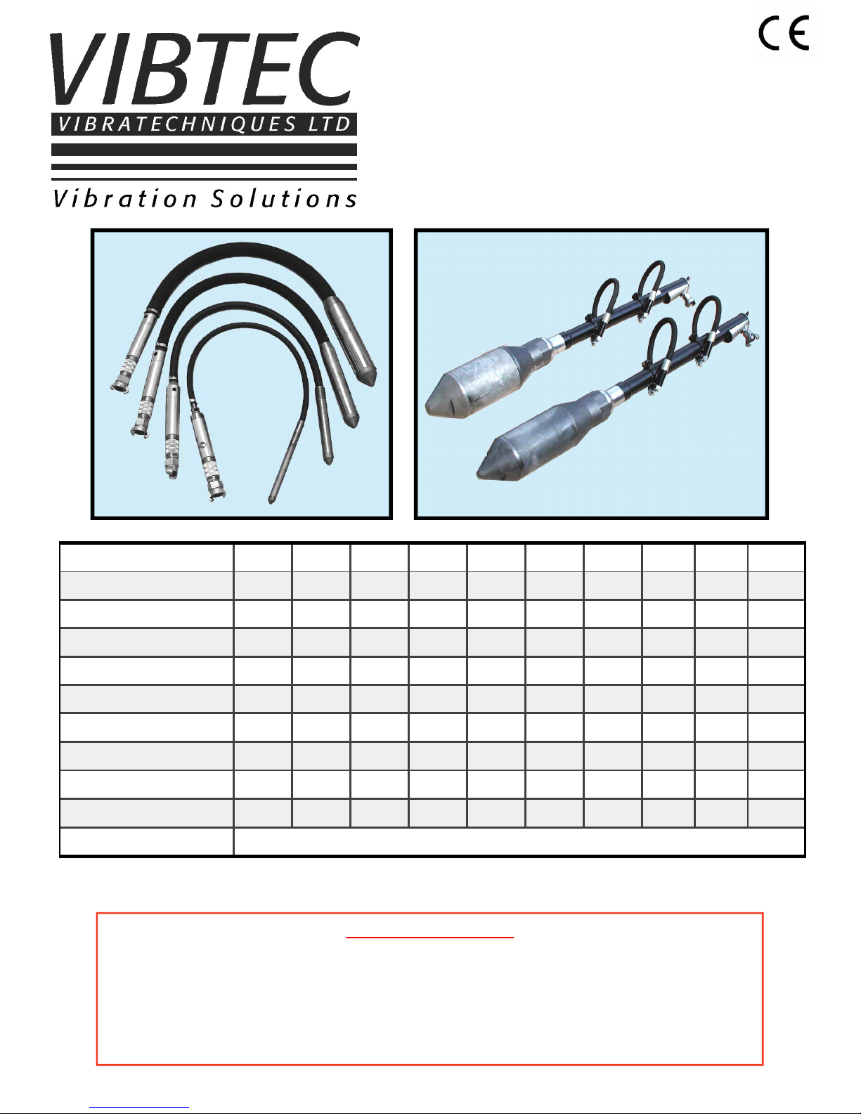
V600
PNEUMATIC INTERNAL VIBRATORS
OPERATING MANUAL
We reserve the right to improve, modify or withdraw specifications or products without notice or obligation.
MODEL V628 V635 V645 V655 V665 V675 V685 V6105 V6140 V6160
Head Diam. (mm)
28 35 45 55 65 75 85 105 140 160
Head Length (mm)
234 278 285 316 327 366 395 395 508 508
Frequency (VPM)
18000 18000 17000 17000 18000 18000 17000 13500 10000 10000
C/F Force (N)
1440 1924 3500 6050 9301 14851 22184 22304 32460 49347
Air Consumption (l/min)
500 608 736 820 1018 1218 1600 2100 2880 3750
Weight (kgs)
4.4 6 8 9 10 15 19 23 35 41.5
Radius of Effectiv. (cm)
16 20 25 38 44 50 55 65 95 105
S P Level (dB)
104.5 107.2 113 109 113 112.1 109 112.2 115 115
Vibration (M.sec2)
3.2 3 2.74 4.5 4.4 2.24 3.1 4.4 4.8 4.8
Air Pressure (psi)
87
Sound and Vibration readings taken 1 metre from the poker head
Air Consumption established with supplied pressure of 6 bar
IMPORTANT NOTICE
Vibrators and vibrating equipment can be dangerous if not used correctly.
1. DO NOT hold steel vibrating heads when running.
2. DO NOT stand or sit on vibratory equipment when running.
3. USE ONLY for the purpose intended.
4. USE ONLY when pneumatic hoses and fittings are securely tightened.
5. ALWAYS wear ear protectors.
Page 2

General Safety
For your personal protection and safety of others around you on site, please read and ensure you fully understand the following safety information. It is the responsibility of the operator to fully understand how to operate
this equipment safely. If you are not sure consult your supervisor.
Points to remember are:
1. Keep unauthorised personnel at a safe distance from the work area.
2. Personal Protective Equipment (PPE) must be worn by the operator whenever this equipment is being
used, i.e. Safety goggles, gloves, ear defenders, dust mask and steel toe capped footwear. Always protect skin from contact with concrete.
3. Ensure that the compressor does not exceed 90 psi.
4. Never dismantle or tamper with any seals or covers fitted. Always check the vibrator thoroughly before
use for condition and safety. If any parts are damaged or missing do not use the vibrator until it is repaired or replaced.
5. The air supply must be switched off before any work is carried out on the vibrator. To prevent accidental
starting of the vibrator, it must be disconnected from the air supply.
6. The vibrator should never be left running out of concrete as it will become extremely hot and internal parts
will be damaged. Caution must be exercised when touching the vibrator head.
7. When the vibrator is not used for long periods of time, store it in a clean, dry and protected environment.
It must be hung up with the head upwards and the control handle open to allow moisture etc. to escape
from the vibrator.
8. Some vibration from vibrator is transmitted through the flexible hose to the operator’s hands. The hose
should not be held within 1 metre from the head of the vibrator at any time. Operational exposure time
may need limiting if fingers become effected.
9. Do not operate the vibrator when you are feeling unwell, tired or when under the influence of alcohol or
drugs.
2
ATTENTION Never use a high pressure compressor.
Page 3

3
General Maintenance
1. Vibrators are delivered without lubrication. Ensure to add oil before starting the vibrator.
2. Before connecting the vibrator, ensure the air line is clean from any water or dirt it may contain.
3. Refill lubricator after every four hours of use with 20/30 S.E.A. non-detergent oil.
4. To start the vibrator it may be necessary to tap the vibrator’s hardened nosepiece onto a firm surface.
5. After use, hang the vibrator with the head upwards and leave the control handle open to drain out of any
water or dirt.
Dismantling and Re-assembly Instructions
1. Replacement of Vane and Rotor
Hold housing (4) in a vice and unscrew nosepiece (1A) - right-hand thread. Remove from the vice and by
angling downwards the rotor is free to drop into the hand ensuring not to cause damage. The parts should
be cleaned and examined . If the nosepiece shows signs of excessive wear, then it should be replaced (see
point 4). Vanes must be a snug sliding fit in the rotor and fitted so that the vane cuts-out face away from the
milled slot in the rotor. Adjust length of vane to 0.1 - 0.15mm shorter than the rotor.
Re-assembly is opposite to the above, but the following should be observed:
1. Lightly oil running faces of the rotor.
2. Insert rotor so that the exhaust holes are in opposite end to the nosepiece.
3. Fit a new ‘O’ ring or fibre washer (2) onto the nosepiece (1A).
Note
Some models (V665-V6105) have nosepieces (1) and separate front closure plates (3). Dismantling is similar
to the above and these two parts are available as spares.
2. Removal of Rear Body, Rear Closure Plate and Hoses
Cut exhaust hose clip (16), pull off exhaust hose (15) from exhaust body (17). Unscrew exhaust body (17)
from lubricator/handle (39/30), then pull out handle to expose hose clip (10). Cut hose clip (10) to release inlet
hose (11) from the handle. Hold housing (4) in a vice and unscrew rear body (12) - left-hand thread, removing
complete with exhaust hose (15). If the hose is to be replaced then unscrew hose sleeve (13), pull out hose
(15) from rear body (12) and remove hose protection spring (14) - only on models V675 - V6105. Using inlet
hose (11) pull out rear closure plate (7), locking ring (8) and inlet hose connector (9). All parts should be
cleaned and the rear closure plate (7) examined for signs of wear (see point 4).
3. Re-assembly
Rear closure plate (7), inlet hose fitting (9) and inlet hose (11) should be inserted into the housing as an assembly, ensuring that the plate is kept square to the housing (4) and pushed onto the housing shoulder. Slide
new locking ring (8) over inlet hose (11) and locate behind rear closure plate (7). If necessary, fix exhaust
hose (15) into rear body (12), insert hose protection spring (14) - only models V675 - V6105, and clamp with
hose sleeve (13). The assembly can then be screwed onto the housing (4) ensuring that a new ‘O’ ring or
fibre washer (2) is fitted. Adjust hose lengths so that the inlet hose (11) protrudes approximately 65mm from
the exhaust hose (15). Slide new clips (10 & 16) onto respective hoses (11 & 15). Pass inlet hose (11)
through exhaust body (17) and fit onto inlet hose connector (18) using hose clip (10). Screw exhaust body
(17) onto control handle (30). Push exhaust hose (15) onto exhaust body (17) and fit hose clip (16).
4. Wear Criterion
The optimum condition of the vibrator turbine assembly to produce maximum speed and therefore power is
determined by the total air gap of the rotor. Ideally this should be between 0.06 - 0.13mm and a total gap
greater than 0.20mm greatly impairs the performance. The length of the rotor is 129.00 - 129.02mm when
assembled at the factory and if worn below 128.70mm, it should be replaced.
OPERATING AND MAINTENANCE INSTRUCTIONS
Models V 628, 635, 645, 655, 665, 675, 685 & 6105
Page 4

4
Models V 628, 635, 645, 655, 665, 675, 685 & 6105
Page 5

5
Ref. Description Qty. V628 V635 V645 V655 V665 V675 V685 V6105
1
Nosepiece 1 - - - - 16265 3551 1602 16246
1A
* 1part Nosepiece / FC plate 1 16310 16206 16216 16227 - - - -
2
* ‘O’ Ring 2 16314 779 1808 2126 16268 2330 1600 16251
3
* Front Closure Plate 1 - - - - 16260 16230 16380 16240
4
Housing 1 16301 16201 16211 16221 16261 16231 16381 16241
5
Rotor 1 16302 16202 16212 16222 16262 16232 16382 16242
6
* Vane 1 16303 16203 16213 16223 16263 16233 16383 16243
7
* Rear Closure Plate 1 16304 16204 16214 16224 16264 16234 16384 16244
8
* Locking Ring 1 16307 16134 7704 7663 16267 7688 - 16252
9
Inlet Hose Connector 1 - - 5521 16225 16225 16235 16245 16245
10
Inlet Hose Clip 2 16313 137 137 5456 5456 5211 5211 5211
11
* Inlet Hose 1 46073 788 788 1583 1583 540 540 540
12
Rear Body 1 16306 2622 7701 1576 16266 3553 1601 16247
13
Hose Sleeve 1 - 2623 1730 1582 1582 1604 1604 1604
14
Hose Protection Spring 1 - - - - - 1479 1479 1479
15
Exhaust Hose 1 171 2021 7985 1584 1584 541 541 541
16
* Exhaust Hose Clip 1 Bandit 3679 2392 75 75 76 76 76
17
Exhaust Body 1 16040 10225 10224 10223 10223 10222 10222 10222
18
Inlet Hose Connector 1 16311 10588 10588 10221 10221 10219 10219 10219
30
Steel Handle Complete 1 16120 16120 16120 16120 16120 16120 16120 16120
31
* Rubber Gland 1 81 81 81 81 81 81 81 81
32
* Gauze Filter 1 156 156 156 156 156 156 156 156
33
Q / R Coupling 1 2512 2512 2512 2512 2512 2512 2512 2512
34
* ‘O’ Ring 2 2273 2273 2273 2273 2273 2273 2273 2273
35
Handle Shaft 1 2261 2261 2261 2261 2261 2261 2261 2261
37
Twist Grip 1 2260 2260 2260 2260 2260 2260 2260 2260
38
Adaptor 1 16042 16042 16042 16042 16042 16042 16042 16042
39
Lubricator Complete 1 10270 10270 10270 10270 10270 10270 10270 10270
40
Lubricator Tube 1 10289 10289 10289 10289 10289 10289 10289 10289
41
‘O’ Ring 1 10273 10273 10273 10273 10273 10273 10273 10273
42
Lubricator Body 1 10271 10271 10271 10271 10271 10271 10271 10271
43
‘O’ Ring 1 2524 2524 2524 2524 2524 2524 2524 2524
44
Oil Filler Screw 1 2265 2265 2265 2265 2265 2265 2265 2265
46
Felt 9 2520 2520 2520 2520 2520 2520 2520 2520
47
Bleed Wire 1 2521 2521 2521 2521 2521 2521 2521 2521
Opt.
Rubber Nosepieces 1 - 16208 16218 16229 19145 3611 - -
Spare Parts
* Most frequently needed parts
Page 6

6
OPERATING AND MAINTENANCE INSTRUCTIONS
Models V6140 & V6160
General Maintenance
1. Vibrators are delivered without lubrication. Before using the vibrator ensure to add 20/30 S.E.A. nondetergent oil.
2. Before connecting the vibrator, ensure the air line is clean from any water or dirt it may contain.
3. These models do not have any oil reservoir thus it is essential to use an air line lubricator.
4. To start the vibrator it may be necessary to tap the vibrator’s hardened nosepiece onto a firm surface.
5. After use, it is important that the vibrator is filled with 60ml of oil and run for 30sec. before storage.
Then hang the vibrator with the head upwards and the on/off valve open to drain out of any water or dirt.
Dismantling and Re-assembly Instructions
1. Replacement of Vane and Rotor
Hold housing (3) in a vice and unscrew nosepiece (1) - right-hand thread. Remove front plate (7) using 16mm
extractor. This allows the rotor (5) and vane (4) to be removed for inspection for wear and damage. Vanes
must be a snug sliding fit in the rotor and fitted so that the vane cuts-out face away from the milled slot in the
rotor. Adjust length of vane to 0.1 - 0.15mm shorter than the rotor.
Re-assembly is opposite to the above, but the following should be observed:
1. Lightly oil running faces of the rotor.
2. Insert rotor so that the exhaust holes are in opposite end to the nosepiece.
3. Fit a new ‘O’ ring (2) onto the nosepiece (1).
2. Removal of Rear Body
Undo nut (36) and remove handle (35), then undo nut (24) and clamp nut (21). You can then unscrew rear
body (6) - left hand thread. Should the rear plate (8) need to be removed, this can be pressed out. You will
need to remove the rotor first from the vibrator to do this.
Re-assembly is opposite to the above, but in order to refit the clamp nut (21), you will need to use M12
female extractor to slightly stretch the inlet hose (17) to line up the thread with the hole in the tube. Once
the clamp nut has been fitted, the rest of the handle can be assembled.
3. Removal of Bush
Hold handle tube (34) in a vice and unscrew nut (10) - right-hand thread. Unscrew locking nut (13) - left hand
thread, the tube will now separate from the rubber bush (14). To fit a new bush (14), replace the locking nut
(13) and push new bush into place. Then place tube with the new bush into the rear body (6) and refit nut (10).
4. Wear Criterion
The optimum condition of the vibrator turbine assembly to produce maximum speed and therefore power is
determined by the total air gap of the rotor. Ideally this should be between 0.06 - 0.13mm and a total gap
greater than 0.20mm greatly impairs the performance. The length of the rotor is 110.00mm when assembled
at the factory and if worn below 109.70mm, it should be replaced.
Page 7

7
Ref. Description Qty. V6140 V6160 Ref. Description Qty. V6140 V6160
1
* Nose piece 1 7500 16393
24
Lock Nut 1 1564 1564
2
‘O’ Ring 2 1534 16395
25
Cover 1 16430 16430
3
Housing 1 7501 16388
27
Slide Valve 1 46155 46155
4
Vane 1 16353 16394
28
Rear Inlet Body 1 16432 16432
5
Rotor 1 7503 16389
29
Exhaust Banjo Fitting Assy 1 16429 16429
6
Rear Body 1 1533 16390
Exhaust Banjo Sleeve 1 16433 16433
7
* Front Closure Plate 1 7502 16392
Exhaust Banjo Inlet 1 16434 16434
8
* Rear Closure Plate 1 7504 16391
30
External Circlip 1 16180 16180
9
Inlet Hose Connector 1 1528 1528
31
‘O’ Ring 2 16181 16181
10
Nut (bush support tube) 1 1539 1539
32
Banjo Spindle 1 16431 16431
11
Front Spacer 1 1542 1542
33
Handle Clamp Assy 2 16355 16355
12
Rear Spacer 1 1544 1544
Tube (flexible handle) 2 1555 1555
13
Nut (rear body) 1 1538 1538
Clamp Collar 2 16367 16367
14
Bush (shock absorbing) 1 1540 1540
Hex Head Screw 2 16373 16373
15
Sealing Ring Rear 1 1541 1541
Hex Nyloc Nut 2 16374 16374
16
‘O’ Ring 1 2330 2330
M8 Plain Washer 2 46017 46017
17
* Inlet Hose 1 2021 2021
34
Support Tube Assy 1 16363 16363
18
Quick Release Joint 1 1654 1654
Bush Support Tube 1 1536 1536
19
* Rubber Gland 1 81 81
Rigid Exhaust Tube 1 16364 16364
20
* Gauze Filter 1 156 156
35
Flexible Handle Assy 2 1657 1657
21
Exhaust Shield Clamp Nut 1 16428 16428
Flexible Handle Connector 2 1556 1556
22
Exhaust Deflector 1 1646 1646
36
Hex Nyloc Nut Thin Type 4 1559 1559
23
Hose Fitting 1 1636 1636
37
M14 Plain Washer 4 16372 16372
Spare Parts
1 2 4 3 6 2
5 8 7
32
9
11 10 12 14
16
15
13
34 17
200
450
1536 Bush Support Tube
22
23
20 21 19 18
24
25
28
31
29
30
27
33
35 36 37
V6160
V6140
* Most frequently needed parts
Page 8

2 CHAPEL ROAD, PORTSLADE, BRIGHTON, BN41 1PF ENGLAND
Tel. +44(0) 1273 430977 Fax. +44 (0) 1273 430978
Web. www.vibtec.com E-mail. sales@vibtec.com
 Loading...