

Vibratrim VT500 Assembly And Instruction Manual
VT500 Assembly and Instruction Manual

2 | P a g e
Table of Contents
Introduction ................................................................................................................................................... 3
Structural Illustration ............................................................................................................................. 4
Packaging details ............................................................................................................................................ 5
Assembly Instructions ................................................................................................................................ 6 -8
Control Panel Illustration ...............................................................................................................................9
Control Panel Instructions ........................................................................................................................... 10
Safety Cautions ............................................................................................................................................ 11
Health Cautions ........................................................................................................................................... 12
Maintenance Instructions ............................................................................................................................ 13
Product Specifications .................................................................................................................................. 13
Warranty ...................................................................................................................................................... 14
**************************************************************************
01

3 | P a g e
Introduction
Thank you for purchasing your VibraTrim VT500. Please read the entire user manual thoroughly before you
begin operating the VibraTrim. This operation manual should be kept available for future reference after you
have read it through.
Please read the assembly instructions on pages 6-9 before beginning assembly.
It may save you some time and headaches.
Our company has the absolute right to alter the design pictures and material color without prior notice. Design,
pictures and material color seen in this manual are solely for illustration purposes.
The VT500 is the sixth model that we have produced. All of our models feature the oscillation style of vibration.
We believe this is the best form of vibration for the body as it is mimicking the natural walking movement. The
VT500 provides two kinds of vibration modes. One mode is the oscillating vibration style plus the second mode
is spiral vibration. The oscillating vibration is the safest, most complete muscle development simply because it
allows the pelvis to move the way it naturally wants to: rotating side to side, the same as when you walk. This
not only limits vibration of the head and neck but it also brings into play the important small stabilizing muscles
of the spine that you ordinarily would not be able to consciously contract and exercise. Improved posture is an
under-rated benefit of exercising with a Pivotal vibration machine. The spiral vibration provides your muscles
ligaments and tendons to be exercised more thoroughly. Many therapists will also use this mode to aid in
recovering from an injury or surgery. The combined vibration mode also increases your circulation providing
benefits to diabetics, cellulite sufferers, etc. Both vibration modes can be used individually or together. Another
major difference, in this model is the ability to design your own training program with the three user definable
programs.
If you should find something wrong with your unit, please notify us right away either by phone
at 253-238-0675 or by email at service@vibratrim.net. You are covered by our outstanding 3
Year Warranty.
There are hundreds of stories of how these units have changed people’s lives. If you have a
story that you would like to share, after using this unit for a while, we would love to hear it.
You can also post your testimony at https://www.facebook.com/VibraTrim.
427 E Stewart St
Milwaukee, WI 53207
253-238-0675 or 414-207-4001
4 | P a g e
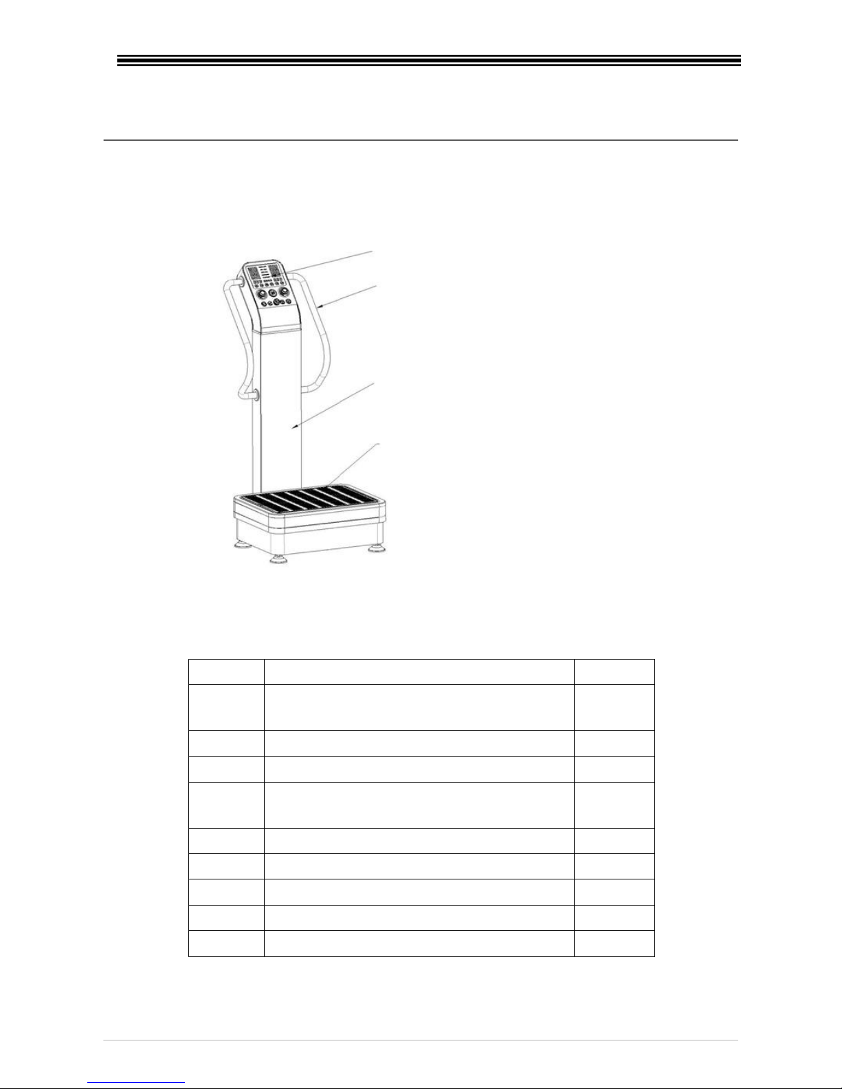
Structural Illustration
Packing Details
Carton 1
Number
Description
Quantity
1
Vibration Base Unit
1
Carton 2
Number
Description
Quantity
1
Support Column with Display Panel Attached
1
2
Parts Package (Contents shown below)
1
3
Power Cord
1
4
User Manual
1
5
Exercise Wall Chart
1
Support Column
Vibration Platform
Handrails
Display & Control Panel
Base Unit
5 | P a g e
Parts List
Number
Description
Quantity
Used in Step #
1
Cross Recess Head Screw M5x10
4
4
2
Cross Recess Head Screw M5x20
8
6
3
Inner Hexagon Head Screw M6x16
8
5
4
Inner Hexagon Head Screw M8x16
10
2
5
Lock Washer 8
10
2
6
Flat Washer 8
10
2
7
Decorative Ring (halves)
8
6
8
Inner Hexagon spanner tool 5 mm
1 9
Inner Hexagon spanner tool 8 mm
1
10
Dual duty screwdriver
1
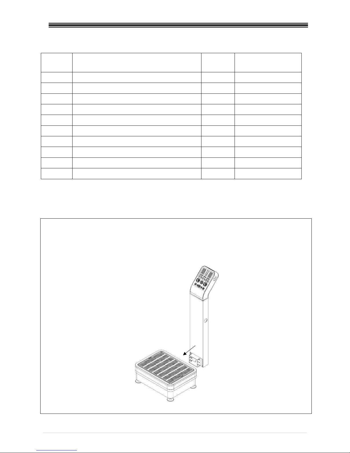
Assembly Instructions
Step 1:
1. Take the machine out of boxes. Inventory all the parts.
2. Connect the 4 pin cable from the support column with the corresponding cable in the base.
3. Assemble the support column and base by sliding them together as shown in the figure
below.
 Loading...