

Vibratrim VT400 User’s Manual & Instruction Book
Creating a new you!!
VT400
USER’S MANUAL & INSTRUCTION BOOK
Two Motors Creating Three Vibration Modes

Table of Contents
●●●●●●●●●●●●●●●●●●●●●●●●●●●●●●●●●●●●●●●●●●●●●●●●●●●●●●●●●●●●●●●●●●●●●●●●●●●●●●●●
Introduction 2
VibraTrim Illustrations
VibraTrim diagram and parts description 3
Control Panel Display & Description 4
Assembly Instructions and Procedures 5
Operation Instructions 6
Preset programs 8
User Programming for USB Flash Drive 9
Features 11
Benefits 12
Exercise Manual and Video 13
Safety Warnings 14
Safety Precautions 15
Contraindications 17
Product Maintenance 18
Specifications - 18
Warranty 19
●●●●●●●●●●●●●●●●●●●●●●●●●●●●●●●●●●●●●●●●●●●●●●●●●●●●●●●●●●●●●●●●●●●●●●●●●●●●●●●●
2

Introduction
Thank you for purchasing your VibraTrim VT400. Please read this entire user manual thoroughly and also view the
online exercise manual listed on page 11 before you begin operating the VibraTrim. This user manual should be
kept available for future reference after you have read it through.
Please read the assembly instructions on page 3 before beginning assembly.
It may save you some time and headaches.
Our company has the absolute right to alter the design pictures and material color without prior notice. Design,
pictures and material color seen in this manual are solely for illustration purposes.
The VT400 is the fourth model that we have produced .All of our models feature the oscillation style of vibration.
We believe this is the best form of vibration for the body as it is mimicking the natural walking movement. The
VT400 provides two kinds of vibration modes. One mode is the oscillating vibration style plus the second mode is
spiral vibration. The oscillating vibration provides a whole body vibration from head to foot. The spiral vibration
provides lower leg vibration. Both vibration modes can be used individually or together. Another major difference,
in this mode,l is the ability to design your own training program with the use of the USB Flash Drive on Page 8.
If you should find something wrong with your unit, please notify us right away either by phone at
888-683-1163 or by email at service@vibra-trim.net. You are covered by our outstanding 2 year
warranty.
There are hundreds of stories of how these units have changed people’s lives. If you have a
story that you would like to share, after using this unit for awhile, we would love to hear it.
4810 Pt Fosdick Dr – Suite E31
Gig Harbor, WA 98335
253-238-0675 Fax 253-238-8188
3
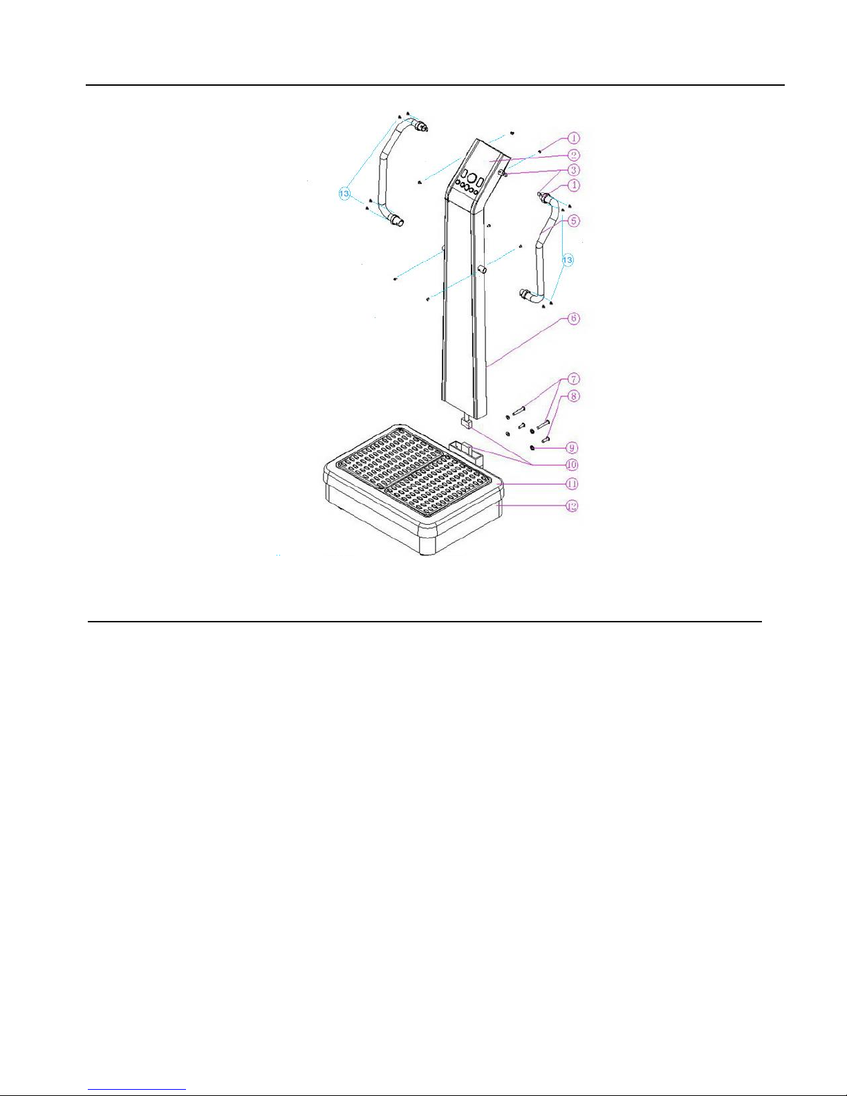
VibraTrim Diagram
Parts Description
1. Screw (M5X8) (4 for each handle) 8. Screw (M8X55) (2 screws)
2. Display Board 9. Gasket (8 pieces)
3. Signal Line Connector (upper) 10.Signal Line Connector(Lower)
4. Decoration Cover 11. Vibration Plate
5. Handrail 12. Base Cover
6. Support Column 13. Screws for Decoration Cover
7. Screw (M8X55) (4 Screws)
4
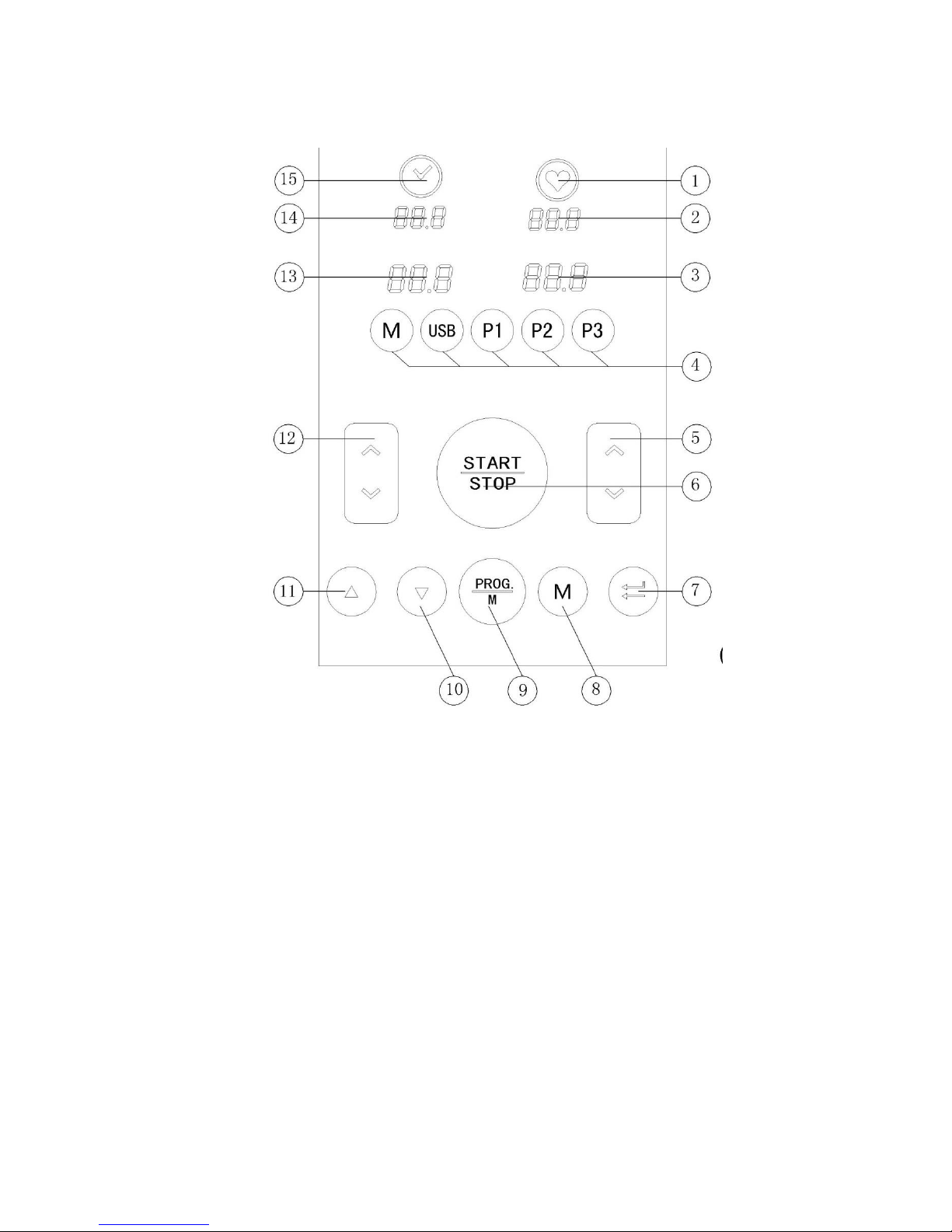
Control Panel Display
Buttons and Displays
1. Heartbeat Indicator 9. Time and Vibration Mode Change Button
2. Heartbeat/Mode Display 10 Time ( -- ) Button
3. Spiral Speed Display 11 Time ( + ) Button
4. Function Indicator 12 Oscillation Vibration Speed/Time Adjust Button
5. Spiral Vibration Speed/Time Adjust Button 13 Oscillation Speed Display
6. Start/Stop Button 14 Time/Vibration Mode Display
7. Time Button 15 Time Indicator
8. Vibration Mode Button
5
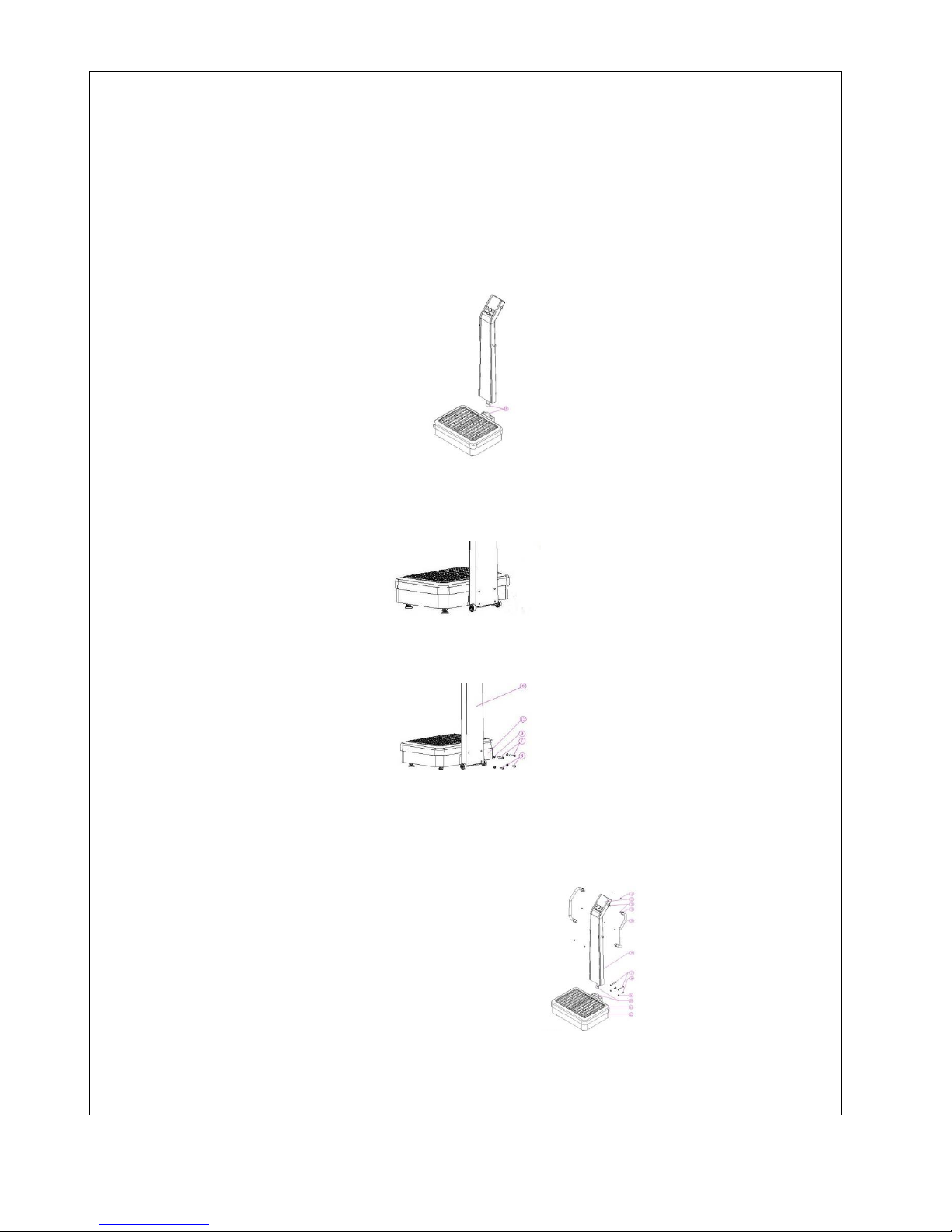
Assembly Instructions
1. This unit is very heavy and requires two adults to assemble. Place the carton on the floor with the top
of the box up. Open the carton and fold back the lid flaps. Then gently roll the carton over on its top. Lift
off the carton, the bottom piece of the Styrofoam packaging and remove the plastic bag. Finally, gently
roll the unit back on its feet and remove the top Styrofoam section. All of the screws have been put in
place where they belong. Simply back them out, put the piece together and reinsert the screws.
2. With the base and the support column out of the cartons the first step is to connect the control wires
from base unit to the support column. One person is needed to hold the support column while the other
connects the wires. Stuff the wire up inside the unit taking care that when the parts are put together the
wire are not pinched. If it is pinched, the cable maybe destroyed and it is not covered under the
warranty.
3. Remove the 6 screws and washers from the back of the base unit. Slide the support column over the
support connection on the back of the base unit. When it is properly aligned the holes in the support
column will line up with the threaded parts on the base unit.
4. Connect the support column and the base unit together with screws that you just removed, with the
Allen wrench provided, or by using a 5mm bit in a electric screw driver.
5. Remove the screws from the support column where the handles attach. Slide the chrome up the
handle to expose the holes where the screws will go. Connect the wires and slide the handles over the
corresponding part on the support column. Attach the screws with the Allen wrench provided or use a
4mm bit with an electric screw driver. Slide the Decorative cover over the screws and attach to the
support column with the screws.
6. Adjust the horizontal cushion to set the machine steady.
7. Connect the power plug
8. Turn on the power switch located at the backside
9. Press the start button to check whether the product operates normally or not.
6
 Loading...