

Page 1
Model 086D50
Impact Hammer
Installation and Operating Manual
For assistance with the operation of this product , contact the Division of PCB
Piezotronics, Inc.
Division toll-free 888-684-0015
24-hour SensorLineSM 716-684-0001
Fax 716-685-3886
E-mail vibration@pcb.com
Page 2

Warranty, Service, Repair, and
Return Policies and Instructions
The informati on contained in this document supersedes all similar i nformation th at
may be found elsewhere in this manual.
Total Customer Satisfaction – PCB
Piezotronics guarantees Total Customer
Satisfaction. If, at any time, for any
reason, you are not completely satisfied
with any PCB product, PCB will repair,
replace, or exchange it at no charge. You
may also choose to have your purchase
price refunded in lieu of the repair,
replacement, or exchange of the product.
Service – Due to the sophisticated nature
of the sensors and associated
instrumentation provided by PCB
Piezotronics, user servicing or repair is
not recommended and, if attempted, may
void the factory warranty. Routine
maintenance, such as the cleaning of
electrical connectors, housings, and
mounting surfaces with solutions and
techniques that will not harm the
physical material of construction, is
acceptable. Caution should be observed
to insure that liquids are not permitted to
migrate into devices that are not
hermetically sealed. Such devices should
only be wiped with a dampened cloth
and never submerged or have liquids
poured upon them.
Repair – In the event that equipment
becomes damaged or ceases to operate,
arrangements should be made to return
the equipment to PCB Piezotronics for
repair. User servicing or repair is not
recommended and, if attempted, may
void the factory warranty.
Calibration – Routine calibration of
sensors and associated instrumentation is
recommended as this helps build
confidence in measurement accuracy and
acquired data. Equipment calibration
cycles are typically established by the
users own quality regimen. When in
doubt about a calibration cycle, a good
“rule of thumb” is to recalibrate on an
annual basis. It is also good practice to
recalibrate after exposure to any severe
temperature extreme, shock, load, or
other environmental influence, or prior
to any critical test.
PCB Piezotronics maintains an ISO9001 certified metrology laboratory and
offers calibration services, which are
accredited by A2LA to ISO/IEC 17025,
with full traceablility to N.I.S.T. In
addition to the normally supplied
calibration, special testing is also
available, such as: sensitivity at elevated
or cryogenic temperatures, phase
response, extended high or low
frequency response, extended range, leak
testing, hydrostatic pressure testing, and
others. For information on standard
recalibration services or special testing,
contact your local PCB Piezotronics
distributor, sales representative, or
factory customer service representative.
Returning Equipment – Following
these procedures will insure that your
returned materials are handled in the
most expedient manner. Before returning
any equipment to PCB Piezotronics,
contact your local distributor, sales
representative, or factory customer
service representative to obtain a Return
Page 3

Materials Authorization (RMA)
Number. This RMA number should be
clearly marked on the outside of all
package(s) and on the packing list(s)
accompanying the shipment. A detailed
account of the nature of the problem(s)
being experienced with the equipment
should also be included inside the
package(s) containing any returned
materials.
A Purchase Order, included with the
returned materials, will expedite the
turn-around of serviced equipment. It is
recommended to include authorization
on the Purchase Order for PCB to
proceed with any repairs, as long as they
do not exceed 50% of the replacement
cost of the returned item(s). PCB will
provide a price quotation or replacement
recommendation for any item whose
repair costs would exceed 50% of
replacement cost, or any item that i s not
economically feasible to repair. For
routine calibration services, the Purchase
Order should include authorization to
proceed and return at current pricing,
which can be obtained from a factory
customer service representative.
Warranty – All equipment and repair
services provided by PCB Piezotronics,
Inc. are covered by a limited warranty
against defective material and
workmanship for a period of one year
from date of original purchase. Contact
DOCUMENT NUMBER: 21354
DOCUMENT REVISION: B
ECN: 17900
PCB for a complete statement of our
warranty. Expendable items, such as
batteries and mounting hardware, are not
covered by warranty. Mechanical
damage to equipment due to improper
use is not covered by warranty.
Electronic circuitry failure caused by the
introduction of unregulated or improper
excitation power or electrostatic
discharge is not covered by warranty.
Contact Information – International
customers should direct all inquiries to
their local distributor or sales office. A
complete list of distributors and offices
can be found at www.pcb.com.
Customers within the United States may
contact their local sales representative or
a factory customer service
representative. A complete list of sales
representatives can be found at
www.pcb.com. Toll-free telephone
numbers for a factory customer service
representative, in the division
responsible for this product, can be
found on the title page at the front of this
manual. Our ship to address and general
contact numbers are:
PCB Piezotronics, I nc.
3425 Walden Ave.
Depew, NY 14043 USA
Toll-free: (800) 828-8840
24-hour SensorLine
SM
: (716) 684-0001
Website: www.pcb.com
E-mail: info@pcb.com
Page 4

1
Installation and Operating Manual
ICP® Impulse Force Test Hammer
Models: 086C01, 086C02, 086C03, 086C04, 086D05
086D20, 086D50, 086D80
Manual Number 19198
Contents:
1.0 Introduction …………………………………………… Page 1
2.0 Description ................................………………………. Page 5
3.0 Installation ...............................................……………... Page 5
4.0 Operation .........................................….……………….. Page 6
4.1 Testing ………………………………………………… Page 6
5.0 Calibration……………………………………………... Page 7
6.0 Maintenance …………………………………………… Page 8
7.0 Cautions ……………………………………………….. Page 8
8.0 Customer Service ……………………………………… Page 9
Appendix- Structure, Behavior and Calibration of Impulse-Force Test Hammers
1.0 INTRODUCTION
The ICP
®
Impulse Force Test Hammer adapts your FFT analyzer for structural behavior
testing. Impulse testing of the dynamic behavior of mechanical structures involves
striking the test object with the force-instrumented hammer, and measuring either the
resultant motion with an accelerometer or the acoustic signature with a microphone.
Structures generally respond as (1) rigid or elastic bodies, (2) finite elements, lumped
constant models, and (3) distributed parameter models conducting stress-strain (sound)
waves.
Testing the functional transfer and transactional characteristics of a mechanical structure
involves mounting the accelerometer at one location of interest, and striking the test
object with the hammer. Modal analysis and modeling involves fixing the
accelerometer(s) at one location, impacting the structure at one point, and then moving
the accelerometer(s) to other points of interest. Integration of the acceleration signal
yields velocity compliance, impedance, and mobility. The hammer impulse consists of a
nearly-constant force over a broad frequency range, and is therefore capable of exciting
all resonances in that range. The hammer, size, length, material, and velocity at impact
Page 5
2
determine the amplitude and frequency content (wave shape) of the force impulse. The
impact cap material generally determines energy content.
Hammer model selection involves determining the size and mass of the hammer structure
which will provide the force amplitude and frequency content required for proper
excitation of the structure under test. Each hammer’s corresponding frequency response
plots indicate the frequency content of the force impulse that can be achieved using the
variety of supplied tips. An extender mass, supplied with most hammers, allows further
tuning by concentrating more energy at lower frequencies.
Large, heavy structures like locomotive frames, tanks, and bridges require an
instrumented sledgehammer; small structures like compressor blades often require minihammers. Some very large structures may require a massive mechanical ram
instrumented with a force-sensing impact head.
All sensors in this system are classified as ICP® (Integrated Circuit Piezoelectric), low
impedance, voltage-mode sensors. Microelectronic, built-in amplifiers standardize
sensitivities within a few percent of nominal value, which is adequate for most dynamic
applications.
PCB® impulse hammers are available in nine different models, including an
automatically-actuated unit (Model 086C09) that is not included in this manual. These
hammers range in size from the mini-impulse hammer to the 12 lb sledgehammer.
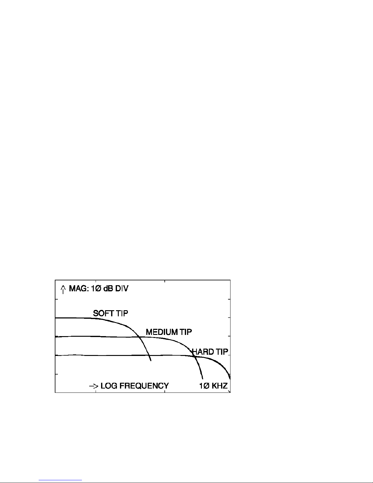
Spectrum of impulse signals from different hammer structures (hard, medium and soft
impact tips) are below:
Model 086C01
Page 6

3
Models 086C02, 086C03, 086C04
Model 086D05
Page 7
4
Model 086D20
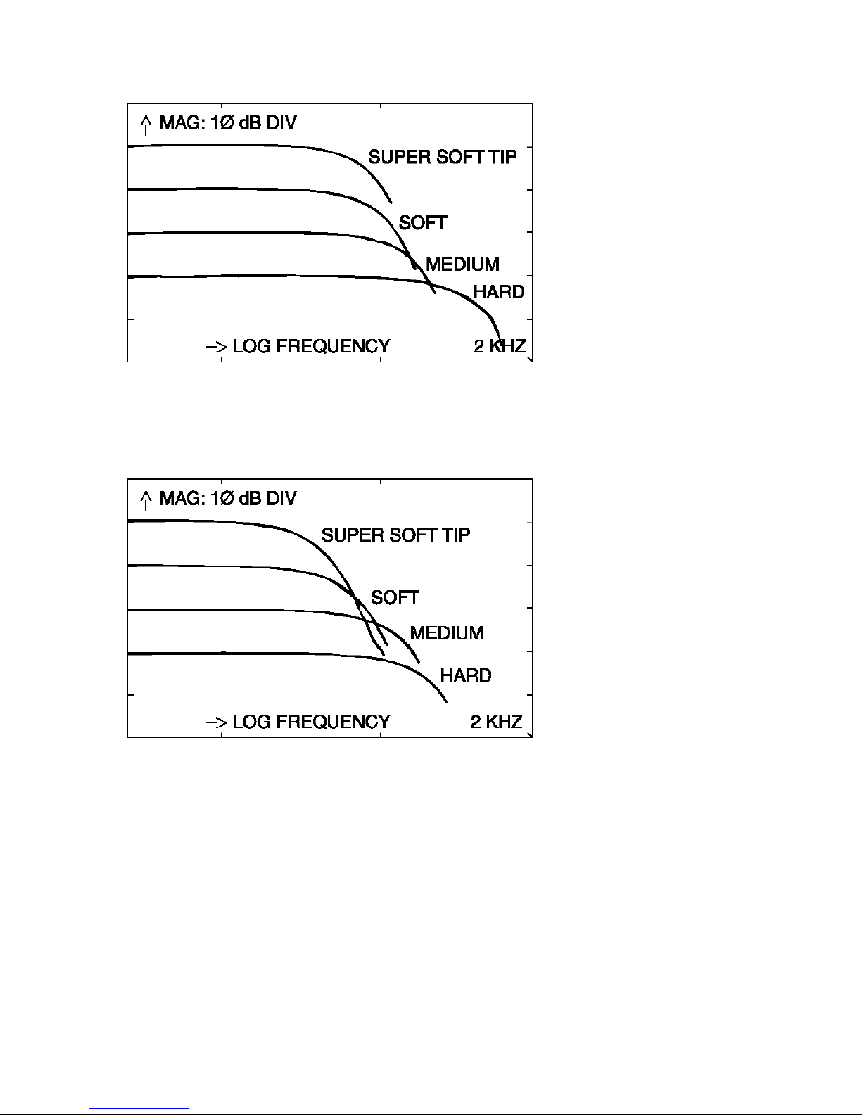
Model 086D50
Page 8

5
Model 086D80
2.0 DESCRIPTION
The hammer consists of an integral, ICP® quartz force sensor mounted on the striking end
of the hammer head. The sensing element functions to transfer impact force into electrical
signal for display and analysis. It is structured with rigid quartz crystals and a built-in,
micro-electronic, unity gain amplifier. The cable is connected to the end of the handle for
convenience, and to avoid connector damage in the event of a “miss hit.”
The ICP® sensor operates over a standard two-wire cable from a PCB® power unit. For
reasons of safety, the easily-repairable ribbon wire cable is intended to be the weak link
in larger hammer design. The ICP® power unit supplies constant current excitation to the
sensor over the signal lead and AC couples the output signal. Many FFT
analyzer/computer systems have ICP® power supply built in.
The hammer is a single, integral unit. Laser-welded construction of the sensor element
insures reliable operation in adverse environments. The mechanical assembly is locked
together with a structural epoxy adhesive so it should not be taken apart except at the
factory.
The striking end of the hammer has a threaded hole for installation of a variety of impact
tips. The tip functions to transfer the force of impact to the sensor, and protects the sensor
face from damage. Tips of different stiffness allow you to vary the pulse width and
frequency content of the force.
3.0 INSTALLATION
The hammer is assembled and locked together with structural adhesive at the factory.
Tips and extender mass install at opposite ends of the hammer via 10-32 threaded studs
(see chapter 4.1 TESTING for hammer/tip extender selection). Cable connections are
illustrated in the system drawing and are generally made via BNC connectors.
Page 9

6
Sensors install and connect according to detail procedures described in specific sensor
manuals. Some common installation methods include stud mount, Petro-wax,
cyanoacrylate adhesive, and magnetic. The method used depends on test conditions and
user preference.
In general, sensors connect to the ICP® power unit at the jack labeled "XDCR." The jack
labeled "SCOPE" is connected to the readout device (FFT analyzer/computer). Consult
ICP® Power Unit Operating Guide for proper installation and operating procedures.
4.0 OPERATION
1. With cables supplied, connect the hammer to a power unit, and then to your analyzer,
as shown in the system and power unit operation guide.
2. Tighten the cable connectors securely by hand to insure good electrical contact.
3. Switch power on, and wait a minute or two for the sensor amplifier to turn on, and for
the coupling capacitor to fully charge.
4. Check the power unit meter for normal operation (meter pointer pointing in green
area).
5. If meter pointer points in the red area, look for shorted cables or connections. If meter
pointer points in the yellow area, look for open cables or connections.
Connect accelerometer(s) in similar manner referring to the appropriate operating guides
for the accelerometer(s) and power unit. When all power unit meters indicate normal
operation (green), proceed with tests, following all sensor, power unit, and analyzer
operating instructions.
4.1 TESTING
To test the behavior of your structure, and to tailor the frequency bandwidth of the force,
follow the following procedures:
1. Strike the test object with the hammer and process the results. Always take several
averages to reduce the effects of spurious noise. CAUTION: Never impact without a
hammer tip properly installed on the sensor element. In the case of the 086D80, the
sensor element is pre-installed with a steel tip.
2. Check the measured results for signal quality (adequate signal-to-noise), no overloads
(overload lights or sharp flattening of time history peaks), and no double impacts.
3. Analyze results for frequency content, and check to insure that the reasonably flat
portion of the force spectrum is sufficient to cover the structural resonances present in the
acceleration spectrum. Often signal energy is sufficient to excite structural resonances at
Page 10

7
20 dB below initial low frequency force levels.
4. Change hammer tips and/or mass to modify its behavior if necessary:
a. For higher frequency response, use a stiffer tip and no extender.
b. For better low frequency response, use a softer tip and install the extender.
c. To increase motion signal energy, increase impact velocity and/or hammer
mass.
IMPORTANT: When using the Model 086D80 Mini Impact Hammer with the Model
084A17 Hammer Handle, best results are achieved when also using the Model 084Al3
Extender Mass. The Model 084Al7 is designed for use in frequency ranges lower than
those reached when using the Model 084Al4 Handle Cable Assembly. The use of the
Model 084Al3 Extender Mass improves the low frequency content of the force input to
the structure, and improves the “feel” of the hammer by offsetting any effective mass
added to the handle base by an attached cable.
5. Repeat steps 1 and 4 until adequate results are obtained.
Generally speaking, the impact tips affect the hammer impulse frequency content, and the
extender affects the signal energy level. Frequency content and energy level are
interrelated, so both will be affected by different hammer structures. Hammer velocity at
impact will also affect both. In general, massive structures with lower stiffness require
the use of the extender and soft impact tip to adequately excite low frequency resonances.
During testing, occasionally check and tighten the electrical and mechanical connections.
Repeated impacting tends to loosen them, which may result in erratic and noisy signals.
Although modal tuning has done much to eliminate this possibility, bouncing (multiple
impacts) or penetration may still occur when using too heavy a hammer on too light a
structure, or section of a structure. This will appear as an oscillatory component
superimposed on the spectrum in your data. Reject such data. Some skill and practice
may still be required when testing lighter structures.
PCB's newest ICP® power units providing greater than 10 volts positive signal range
(three x 9 volt batteries) prevent undetected overloads in the power unit. Distortion,
undershoot, and oscillation of the impulse time history as viewed on the analyzer display
is caused by ringing of the analyzer's anti-aliasing filters, which is their normal behavior.
To view the correct impulse waveform, switch the analyzer to a high-frequency range.
5.0 CALIBRATION
Calibration involves testing the functional transfer behavior (sensitivity) of the sensor
structure in controlled transactions and environments.
Different hammer structures have different sensitivities, because the test structure
experiences a force greater than the crystal-sensing elements. The force of impact on the
Page 11

8
test structure is a function of the total mass of the hammer, while the force on the crystals
is a function of only the mass behind them (the impact tip is in front of the crystalsensing element). Their differences, which depend on the ratio of the tip mass to the head
mass, is automatically compensated for when the hammer is properly calibrated, since
the extender mass is behind the sensing element. When used, it results in a slight
increase in voltage sensitivity (as shown on calibration certificate). Each hammer
structure can be easily calibrated to ensure the most accurate data.
A hammer can be calibrated by hitting a freely-suspended mass instrumented with a
quartz reference accelerometer. According to Newton's second law of motion, at any
instant in time, the force experienced by the mass is simply the mass multiplied by the
measured acceleration. On a storage oscilloscope, dividing the peak output signal of the
hammer (mV) by the mass (lb or kg), times the peak acceleration (g), gives the hammer
sensitivity directly in mV/lb or mV/kg.
Calibration on a FFT analyzer produces the same result as a function of frequency. Since
the transfer function of a mass behaving as a rigid body is a consistent (1/M) ratio, the
force and the acceleration signals produces a calibration constant (ideally 1/M) for each
discrete frequency. The effects of a non-modally tuned hammer will be readily apparent
when performing this calibration.
The mass, pendulously suspended or placed on a piece of foam rubber, will behave as a
rigid body. Hitting such an instrumented mass is also a good way of checking the normal
operation of the hammer and instruments prior to testing. This procedure builds
confidence in data results.
6.0 MAINTENANCE
The sealed construction of the sensing element and the bonded construction of the
hammer preclude field maintenance. Should service be required, first replace the cables
(cables are often the source of trouble) and test operation again. If necessary, return the
unit to the factory with a note describing the problem.
7.0 CAUTIONS
Although hammers are very rugged in construction, damage can result from misuse.
When observed, the following precautions can ensure long life and accurate data.
1. Do not attempt to dismantle sensor element from hammer structure. All service should
be performed at the factory.
2. Never generate more than 5 times the rated impact force range with any hammer.
Generally, observe the force rating for five volts output. Excessive impact force may
destroy the built-in miniature electronics.
Page 12

9
3. Never strike an object without an impact tip properly installed in front of the forcesensing element. Damaging the precision-lapped surface of the hammer sensor can affect
its behavior.
4. During testing, periodically check and tighten tip, extender and cable connections to
ensure continued proper operation. Machined flats in the tips and extender facilitate
tightening and removal.
5. Do not apply voltage to unit without constant current protection.
6. Do not apply more than 20 mA of current.
7. Do not exceed 30 volts supply voltage.
8. Do not subject units to temperatures above 250 degrees F (121 degrees C).
8.0 CUSTOMER SERVICE
PCB Piezotronics guarantees Total Customer Satisfaction. If, at any time, for any
reason, you are not completely satisfied with any PCB product, PCB will repair, replace,
or exchange it at no charge. You may also choose, within the warranty period, to have
your purchase price refunded. Contact PCB Vibration Division Customer Service
personnel by calling toll-free in the USA at 1-888-684-0013 or outside the USA at 716684-0001, or send an email to vibration@pcb.com
PCB offers to all customers, at no charge, 24-hour phone support. This service makes
product or application support available to our customers, day or night, seven days a
week. When unforeseen problems or emergency situations arise, call the PCB 24-Hour
Sensorline at (716) 684-0001, and an application specialist will assist you.
3425 Walden Avenue, Depew, New York 14043-2495 USA
USA Toll Free Phone: 888-684-0013
International Phone: 716-684-0001 Fax: 716-685-3886
E-mail: vibration@pcb.com Website: www.pcb.com
Page 13

Page 14

 Loading...