

Page 1
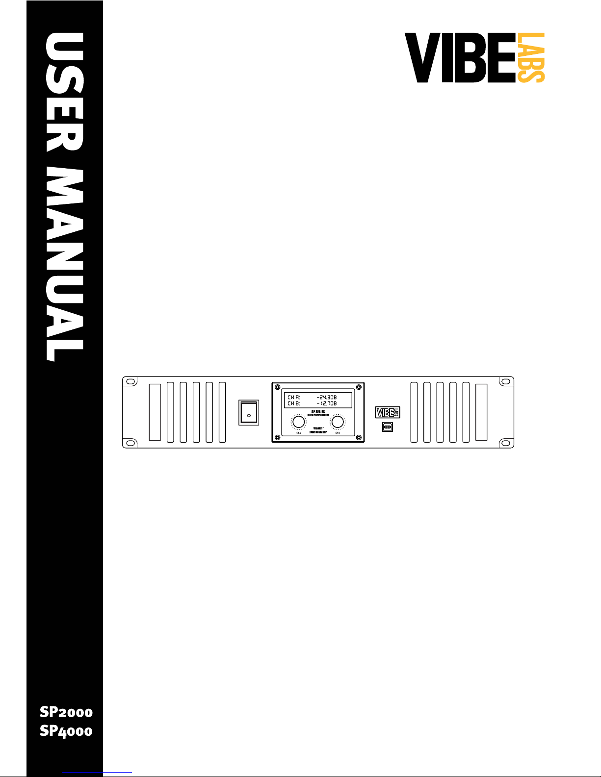
SP SERIES
Digital Power Amplifiers
Page 2

Page 2
SP Series User Manual
IMPORTANT SAFETY INFORMATION
In these safety instructions the word “product”
refers to the SP2000 and SP4000 power amplifiers
from Vibe Labs, Inc.
Read instructions — All the safety and
operating instructions should be read before
the product is operated.
Retain instructions - The safety and operating
instructions should be retained for future
reference.
Heed Warnings — All warnings on the product
and in the operating instructions should be
adhered to.
Follow Instructions — All operating and
maintenance instructions should be followed.
AC Power Supply — Connect the product only to
a properly sized and fused AC supply circuit of
the correct voltage.
Grounding — Use only with a proper Earth
ground and the supplied 3 conductor power
cord.
Power Cord Protection — Power cords should
be routed so that they are not likely to be
walked on or pinched by items placed upon or
against them. Pay particular attention to plugs
and the point from which the cords exit the
product.
1.
2.
3.
4.
5.
6.
7.
Cleaning — Unplug this product from the wall
outlet before cleaning. Do not use liquid or
aerosol cleaners.
Disconnect — The product should be
disconnected from the power supply during
power outages, lightning storms or when
unused for long periods of time.
Moisture - The product should be protected
from moisture and should not be used in or
near water.
Service and Repair — Refer all service and
repair as required to qualified service
personnel. Do not attempt repair.
Ventilation — Ensure that the product is
installed where adequate airflow is present and
that the ventilation openings are unobstructed.
Placing or Moving — Do not place on an
unstable cart, stand, bracket or table. The
product may fall, causing serious injury to
a child or adult, and serious damage to the
product. A product and cart combination
should be moved with care. Quick stops,
excessive force, and uneven surfaces may
cause the product and cart combination to
overturn.
Cover — To prevent the possibility of electrical
shock do not remove the cover.
8.
9.
10.
11.
12.
13.
14.
NOTE: This equipment has been tested and found to comply with the limits for a Class
B digital device, pursuant to Part 15 of the FCC Rules. These limits are designed to
provide reasonable protection against harmful interference in a residential installation.
This equipment generates, uses and can radiate radio frequency energy and, if not
installed and used in accordance with the instructions, may cause harmful interference
to radio communications. However, there is no guarantee that interference will not
occur in a particular installation. If this equipment does cause harmful interference to
radio or television reception, which can be determined by turning the equipment off
and on, the user is encouraged to try to correct the interference by one or more of the
following measures:
Reorient or relocate the receiving antenna.
Increase the separation between the equipment and receiver.
Connect the equipment into an outlet on a circuit different from that to which the
receiver is connected.
Consult the dealer or an experienced radio/TV technician for help.
•
•
•
•
FCC Part 15 Compliance
Page 3
Page 3
SP Series User Manual
Welcome to Vibe Labs
Thank you for investing in the SP Series of professional power
amplifiers from Vibe Labs! Your trust is well placed in what we
believe to be one of the best specified, best designed and best
built digital power amplifiers available. We have spent countless hours poring over the
many details that make up a sophisticated product like the SP series to ensure that you
enjoy many years of flawless performance.
Please take the time to read through this User Manual in order to fully appreciate all of
the features and benefits of the SP series. Or, if you are experienced go ahead and read
over the Quick Start on page 4. Ultra-seasoned “road dogs” might be tempted to skip
even those instructions. If that’s the case then at least please check these two items so
that we don’t blow anything up:
1. Make sure the AC VOLTAGE SWITCH is set correctly for your region.
2. Do not connect a BRIDGED MONO load to the amplifier; it will fail immediately.
Now if you’d like to discover all of the other features such as the switchable noise gate,
auto-mute gain control and security lock functions or you’d like more information about
controlling and monitoring the amplifier from a computer, then you’d best read on. The
SP series has a lot to offer and we want you to get the very most out of it.
Finally, I’d like to encourage you to think about how you may be able to reduce your
carbon footprint in this age of environmental awareness. At Vibe Labs we’ve made a
commitment to become carbon neutral by reducing, re-using and recycling. While we
can’t do it alone we know that every little bit helps. You can do your part by turning off
devices (including this amplifier) when not in use. It’s only one small step but it will
make a difference.
Thanks again for putting your trust in Vibe Labs.
Sincerely
Costa Lakoumentas
Founder & CEO
Page 4
Page 4
SP Series User Manual
QUICK START GUIDE
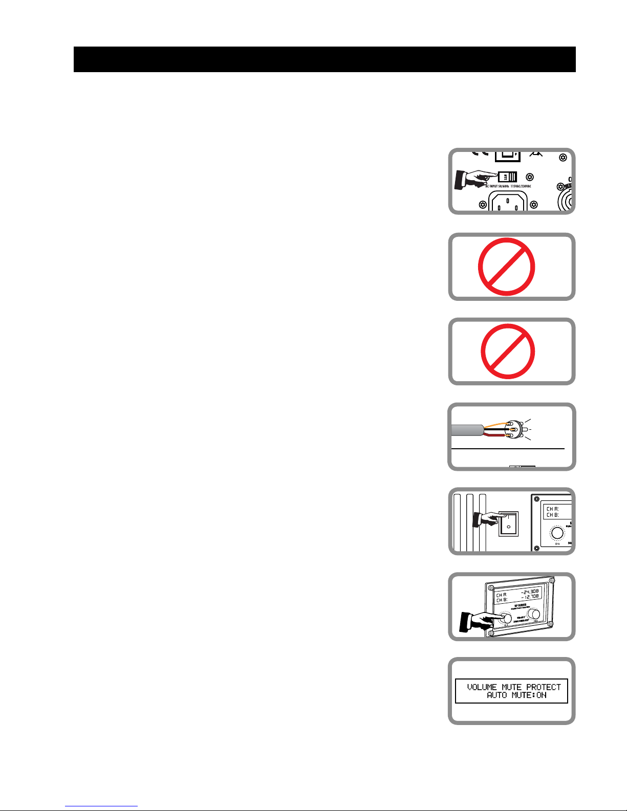
It is strongly recommended that you read this User Manual in its entirity. However if you
need to get up and running immediately please observe the following :
<2 OHMS
Do not connect speakers with a total load impedence
of less than 2 Ohms per channel.
2.
BRIDGE
Do not bridge the amplifier outputs.3.
12
3
Pin 2 (+)
Pin 3 (-)
Pin 1 (S)
Balanced XLR
Left (+)
Balanced Euroblock
Connect input signals.4.
Adjust gain as needed.6.
115
VibeNET
IN OUT
OUTPUTS
Check the voltage select switch and make sure it is set
correctly for your region.
1.
Connect to AC power and turn amplifier ON.5.
Set the MUTE PROTECT mode as described on Page
16 of this manual.
7.
Page 5
Page 5
SP Series User Manual
SP series power amplifiers combine
sophisticated digital signal processing
with high-efficiency Class D power
amplification for a wide range of
professional audio applications. Included
VibeNET™ SP software allows complete
control over all signal processing, gain
and test functions as well as real-time
monitoring of levels and temperature from
a connected PC either by USB or Cat5
cabling.
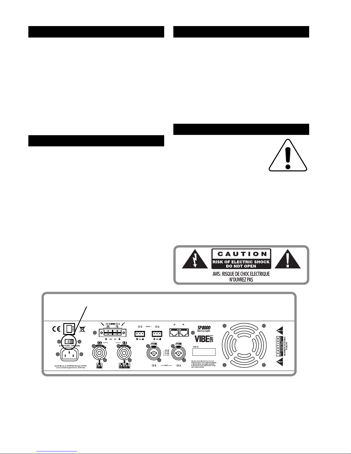
SP Series amplifiers may be
operated on either 115VAC
or 230VAC. The correct
voltage is selected on the
rear panel through the
voltage select switch. While all amplifiers
are set correctly at the factory for their
intended destination country you are
advised to confirm the setting before
connecting the amplifier to the power
supply for the first time.
AC Voltage Select
115
VibeNET
IN OUT
OUTPUTS
This product is designed to be connected
and used only as recommended in this
User Manual. To ensure electrical safety
it must be connected to a properly
rated and fused AC power supply that
is grounded. Do not connect to a power
supply that is ungrounded or where
the power cord is missing the ground
connection.
1. INTRODUCTION
2. UNPACKING & INSPECTION
The shipping carton contains:
SP series amplifier
Printed copy of this user manual
IEC AC power cable
Two Euroblock Input connectors
One Euroblock Output connector
One USB cable
One CD-ROM with VibeNET software
The amplifier should be checked
for any damage that may have been
caused in transport. Verify that all of
the components are in the box. Please
consider recycling the carton.
•
•
•
•
•
•
•
3. SAFETY
4. AC VOLTAGE
© Copyright 2009, Vibe Labs, Inc.
Vibe Labs™ is a trademark of Vibe Labs, Inc.
All other trademarks used in this manual are the property of their respective owners.
No part of this manual may be copied, reproduced, scanned or posted witout the express
written permission of Vibe Labs, Inc.
Page 6
Page 6
SP Series User Manual
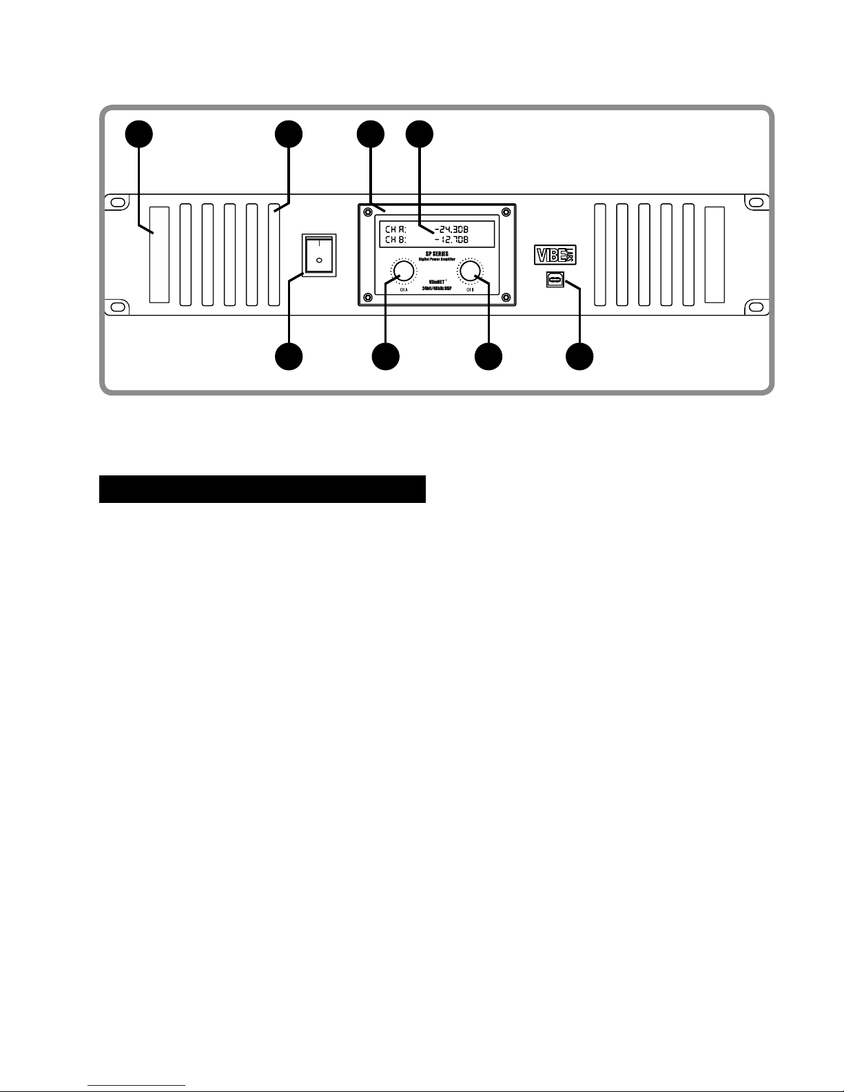
1. Carrying handles.
2. Air vents – DO NOT BLOCK!
3. Display bezel.
4. LCD display screen.
1 32 4
5 6 7 8
5. AC power switch.
6. Channel A Gain control / Setup encoder.
7. Channel B Gain control / Setup encoder.
8. USB connection point (to computer).
5. FRONT PANEL
Page 7
Page 7
SP Series User Manual
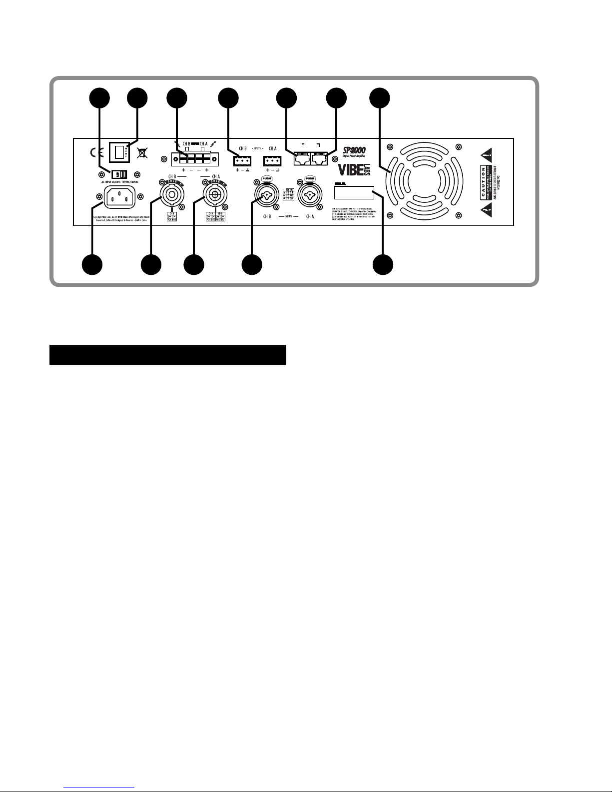
1. AC Voltage select switch.
2. Magnetic Circuit Breaker.
3. Euroblock speaker outputs.
4. Euroblock line level inputs.
5. VibeNET™ input jack (to computer).
6. VibeNET™ output jack (to next amplifier).
115
VibeNET
IN OUT
OUTPUTS
1 2 3 4 5 6 7
8 9 10 11 12
7. Cooling fan grille – DO NOT BLOCK.
8. AC Input socket (IEC).
9. Channel B speaker output (NL4).
10. Channel A&B speaker output (NL4).
11. Combination XLR/TRS line inputs.
12. Serial Number label.
6. REAR PANEL
Page 8
Page 8
SP Series User Manual
SP series amplifiers are fitted with the
three most popular connector types for
signal input; XLR/TRS combination input
jacks as well as detachable Euroblockstyle connectors.
All connectors will accept balanced or
unbalanced signals from a variety of
high and low-impedance source devices.
For optimal performance and signal
integrity it is highly recommended that all
signal sources be balanced. Unbalanced
connections can introduce noise and
hum into the signal chain and should be
avoided.
Keep the connecting cables between the
amplifier and the source device as short
as possible to minimize the potential
for interference from other electrical
devices. Where possible run signal cables
away from sources of electro-magnetic
interference such as lighting dimmers,
refrigeration compressors, electric
motors, fans and other similar devices.
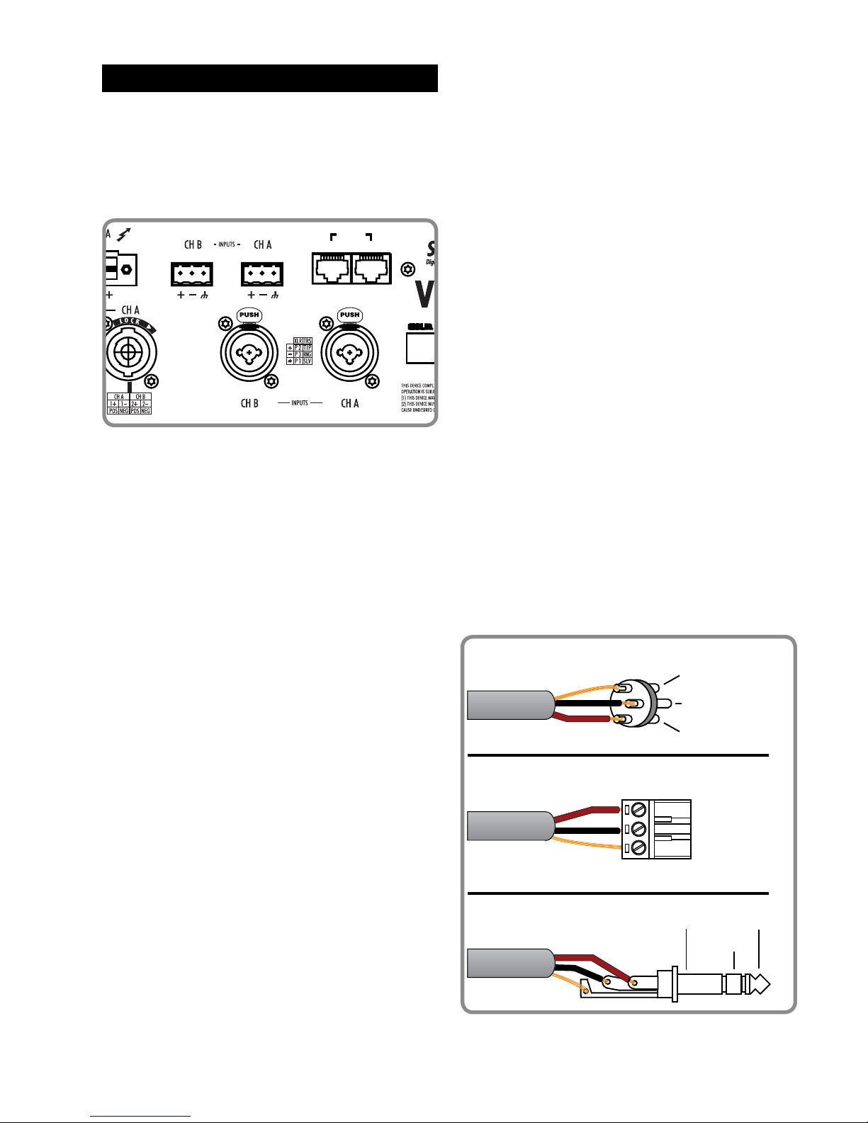
Balanced Signals
Balanced signals use cables with two
conductors plus a shield drain wire. One
conductor is labelled (+) and represents
the POSITIVE or HOT terminal. The second
conductor is labelled (-) and represents
the NEGATIVE or COLD terminal. The drain
wire is labelled (S) and represents the
SHIELD or GROUND terminal.
XLR connectors should be wired as per
AES14-1992, with Pin 2 Positive-polarity,
Pin 3 Negative-polarity and Pin 1 Shield.
Euroblock connectors provide a quick and
secure audio connection that does not
require soldering yet allows the connector
to be detached easily as needed.
Matching terminal plugs are provided for
each channel and are installed on the
amplifier. Terminate the wires as shown in
the diagram and as printed on the rear of
the amplifier.
Balanced TRS connectors are to be wired
with Tip Positive-polarity, Ring Negativepolarity and Sleeve Shield.
VibeNET
IN OUT
12
3
Pin 2 (+)
Pin 3 (-)
Pin 1 (S)
Sleeve(S)
Ring (-)
Tip (+)
Balanced XLR
Balanced TRS
Right (S)
Center (-)
Left (+)
Balanced Euroblock
7. INPUT CONNECTIONS
Page 9
Page 9
SP Series User Manual
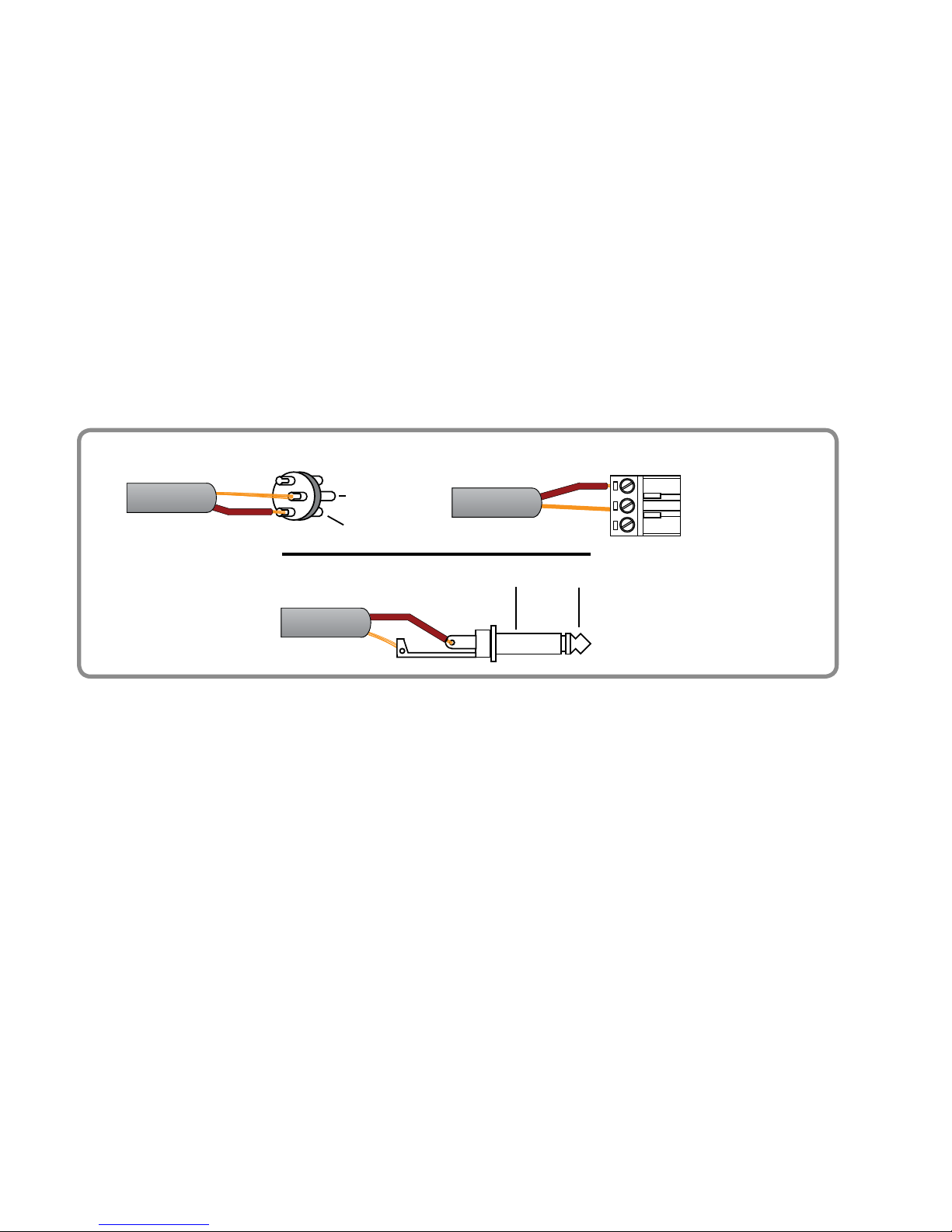
Unbalanced Signals
Unbalanced connections are not
recommended for professional
applications because they are susceptible
to interference from other electrical
devices. Depending on the cable length
and routing unbalanced connections may
also pick up radio interfernce from mobile
telephones or communication devices.
Unbalanced connections use only two
conductors, where one conductor is
labelled (+) and represents the POSITIVE
or HOT terminal. The second conductor
12
3
Pin 2 (+)
Pin 3 (S)
Sleeve(S)
Tip (+)
Unbalanced XLR
Unbalanced TRS
Center (S)
Left (+)
Unbalanced Euroblock
is actually the shield drain wire and is
labelled (S) and represents the SHIELD or
GROUND terminal.
Unbalanced sources may be connected
using any of the three connector types;
XLR, ¼"-TRS or Euroblock.
Connect unbalanced sources using the
positive conductor to the amplifier’s
positive (+) terminal and the shield to the
negative (-) terminal. Do not connect the
shield to the shield (S) terminal on the
amplifier.
Page 10
Page 10
SP Series User Manual
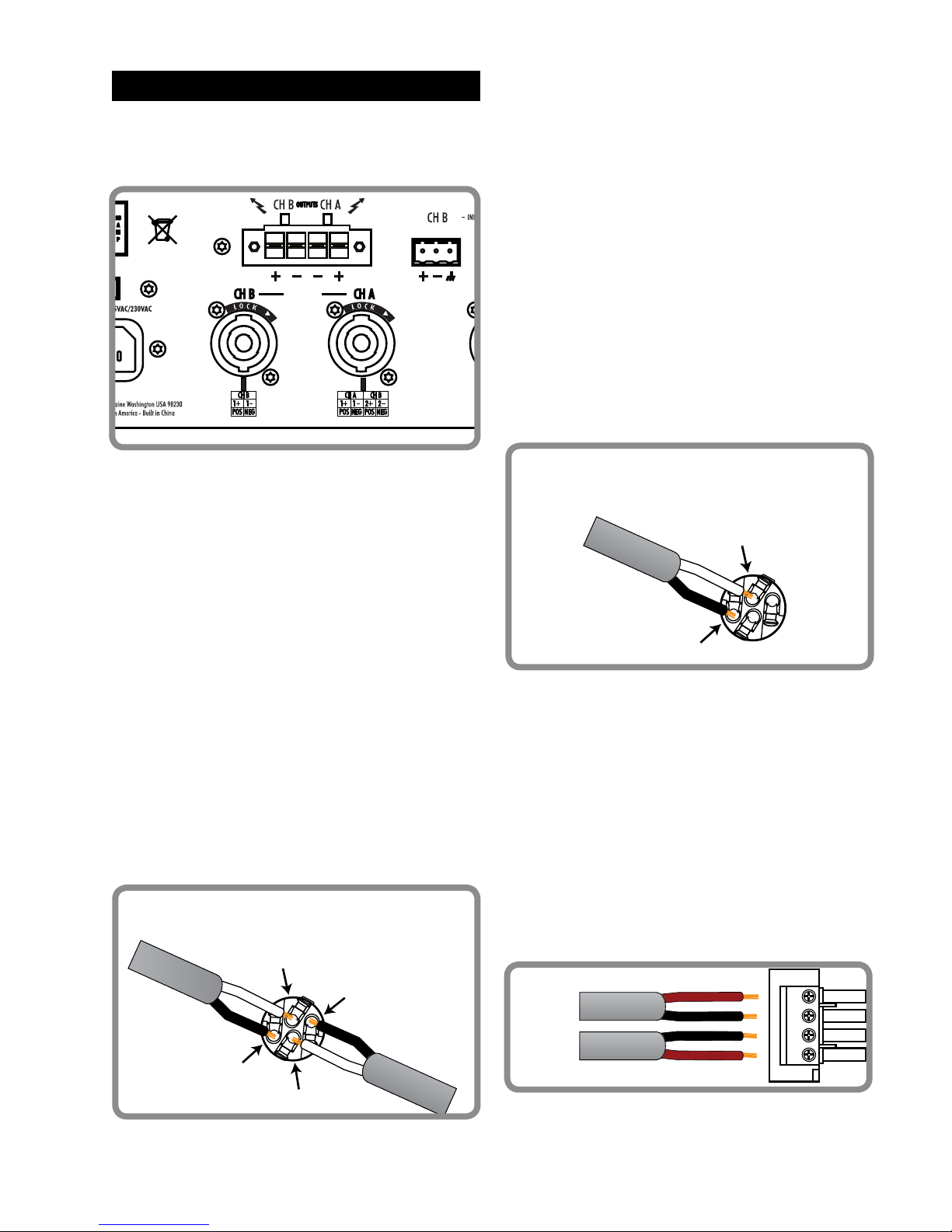
Amplifier outputs are provided on two
Neutrik NL4 connectors and a detachable
four-pin Euroblock connector.
Channel B Connector
The channel B connector is wired to the
channel B amplifier only.
When wiring the cable connector use
pins 1+ and 1-, with + connected to the
positive terminal of the speaker and connected to the negative terminal.
1+
1-
Channel B
NL4 Connector Wiring
1+
1-
2+
2-
Channel A
NL4 Connector Wiring
VibeNET
IN OUT
OUTPUTS
The NL4 connectors are will accept
industry standard Neutrik
®
NL2 or
NL4 cable connectors. The Euroblock
connector is wired in parallel with the NL4
connectors, allowing both connections
to be used in tandem. Minimum load
impedance is 2 Ohms per channel.
Channel A Connector
The channel A NL4 connector is factory
wired to both amplifier channels. This
permits connection of both amplifier
channels to two separate speaker loads
using only one cable connector. This
wiring arrangement is recommended for
bi-amp applications where one cable
feeds a speaker cabinet.
When wiring the cable connector use
pins 1+ and 1- for channel A and pins 2+
and 2- for channel B, with + connected to
the positive terminal of the speaker and
- connected to the negative terminal. DO
NOT COMBINE THE COMMON TERMINALS
OR WIRE FOR BRIDGED OPERATION.
Euroblock Connector
The Euroblock connector is supplied with
a matching 4-conductor plug. This plug
will accept up to 8 AWG (3.26mm) solid or
stranded wire. Simply strip the wire back
approximately 5/16” (8mm), insert in
the opening and turn the clamping screw
with a flat-bladed screwdriver. The plug
is inserted in the connector and securely
fastened with the two security screws
located on the plug.
CH B
(+)
(+)
CH A
9. OUTPUT CONNECTIONS
Page 11

Page 11
SP Series User Manual
DANGER: SP series
amplifiers are not designed
for Bridged operation.
The two channels must be
connected individually to
electrically isolated loads with balanced
wiring (2 conductors). Do not under any
circumstances connect the two amplifier
channels together in Bridge mode or
combine the ground (Negative-polarity)
connections. Such connections will result
in immediate catastrophic failure of the
amplifier and void the warranty.
SP series amplifiers are designed to be
used in conjunction with a PC compatible
computer. Initial setup of the signal
processors requires a computer with the
supplied VibeNET™ application software
installed. Although a computer is not
required after initial setup one can be
used to provide real time monitoring of
the amplifier’s output levels and internal
temperature.
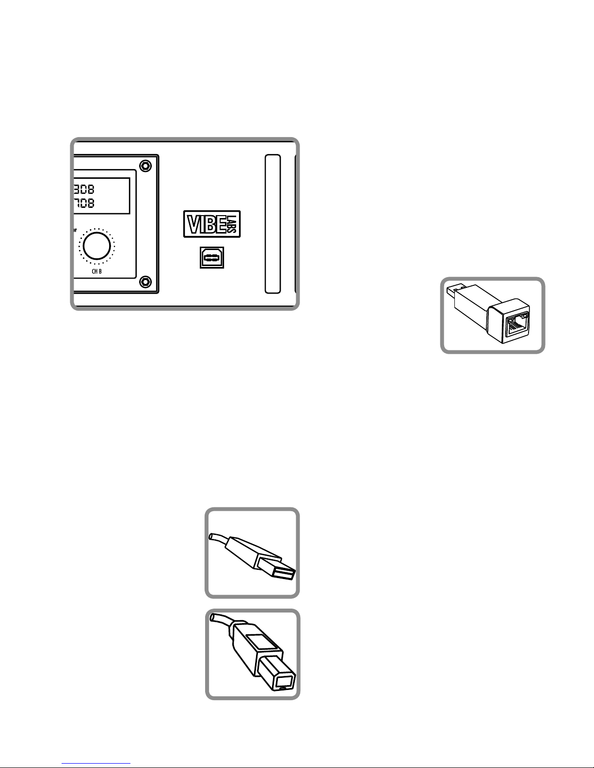
Connection between the computer and
the amplifier is made using the supplied
USB cable. Connect one end to an
available USB port on the computer and
the other end to the front panel mounted
USB connector on the amplifier.
Two network ports are provided on the
rear panel for the creation of larger
systems consisting of more than one
amplifier. These ports allow for the
connection of up to 256 amplifiers to
one computer using standard Category 5
network cables. Use the optional ptional
LiNC serial interface to interface between
the computer and the network ports.
Further details on the setup and operation
of the VibeNET™ software can be found
in the documentation and help files
supplied with the application.
VibeNET™ Software
The VibeNET™ software application is
furnished on a CD-ROM. Please check the
Vibe Labs website for the latest version
information.
VibeNET™ requires a PC compatible
computer running the Microsoft Windows
2000/XP/VISTA operating system. For
further detail consult the help file in the
application itself.
10. COMPUTER CONNECTIONS
Page 12
Page 12
SP Series User Manual
The USB cable has a
type A connector on the
end that connects to
the computer as shown
here.
The end which
connects to the
amplifier has a type B
connector.
USB Connection
Connection via USB requires a compatible
PC running Windows 2000/XP with a USB
1.1 or later communication port and a
suitable USB A to B cable such as the one
supplied with every SP amplifier.
VibeNET Network Connection
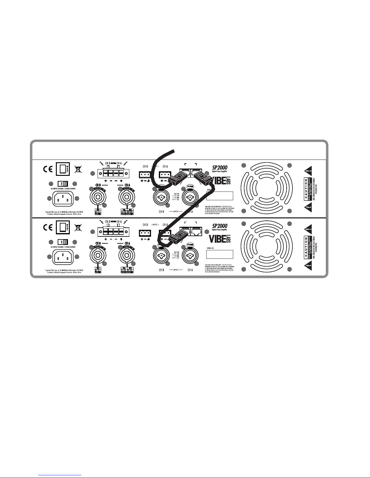
The VibeNET™ network ports on the
rear panel allow the connection of up to
256 amplifiers to one computer using
standard Category 5 network cable, also
known as Ethernet cable. The ports are
labelled IN and OUT, allowing connection
of multiple amplifiers in a “daisy chain”
arrangement without the use of hubs or
other network hardware.
Connection of a computer to the
VibeNET™ ports requires the use of
an optional computer interface. Two
interfaces are offered; one for use with
a USB port on the host computer and
VibeNET™ SP software must be installed
in order to connect with and control the
amplifier. Follow the instructions included
with the installation disk to fully install
the application before connecting an
amplifier to the computer.
Once the software is installed simply
connect the USB cable to the computer
and then connect to the SP series
amplifier. Windows will recognize the
amplifier after which it can be controlled
by the computer.
another model for
use with a standard
serial port. Both
interfaces connect
using Cat5 cable and
can address up to 64
amplifiers on one cable network.
Follow the instructions supplied with
the serial interface to install it on your
computer. In some cases you may be
required to install driver software. Once
installed the interface can be connected
to the amplifiers using Cat5 cables.
VibeNET™ is designed to address up to
256 devices in groups of 64. A separate
serial interface is required for each group
of 64 amplifiers that will be connected to
one computer. Ensure that the computer
offers a sufficient number of available
COM ports to support the number of
interfaces required in the system.
Before connecting the interface to the
amplifiers ensure that the amplifier
network addresses have been set and
that there are no conflicts. Refer to the
section on Setup Amplifier ID for further
information.
Page 13
Page 13
SP Series User Manual
Connect the network cable to the
computer interface, then plug the other
end of the cable into the VibeNET™ IN
port of the first amplifier in the network.
A cable connected to the OUT port can
connect to the next amplifier in the
network.
NOTE: VibeNET™ SP software must be
installed on the connected computer
in order to control and monitor an SP
amplifier.
115
VibeNET
IN OUT
OUTPUTS
115
VibeNET
IN OUT
OUTPUTS
TO COMPUTER
TIP: VibeNET™ SP software requires you
to choose the computer’s COM port that is
being used to connect to the SP amplifier.
To find out which COM port the interface
is using simply open Windows System
Information, Components and USB or
Ports, depending on the type of interface
you are using.
Page 14
Page 14
SP Series User Manual
3
1
2
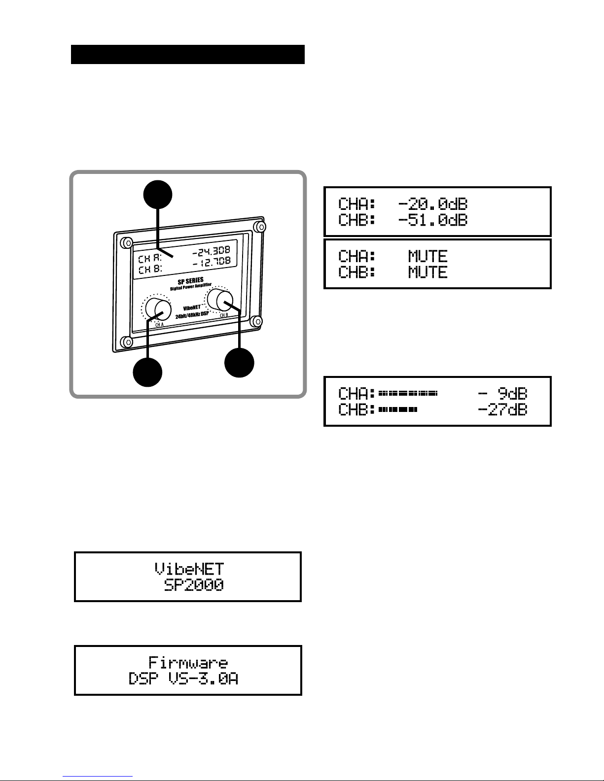
The LCD display screen serves several
important functions. During normal
operation it indicates amplifier output
and gain settings. In setup mode it
permits access to and control over several
system options.
Power On Display
On system power-up the screen will
display the amplifier model number for
approximately 3 seconds.
Control Section
1. Channel A encoder and switch.
2. Channel B encoder and switch.
3. LCD display screen.
Gain Control
During normal operation the encoders
serve as gain controls. Rotate clockwise
to increase gain and counter-clockwise
to decrease. Press and release either
encoder to display the current gain
settings for both channels. The screen will
indicate the gain in decibels relative to
full output.
VU Display
The display will indicate relative output
level with a bar graph as well as a numeric
value calibrated in decibels.
The screen will then display the version
number of the currently loaded Firmware.
11. DISPLAY & CONTROLS
Page 15

Page 15
SP Series User Manual
Setup Mode
Each of the encoders offers access to a
separate group of system setup options.
These options are accessible when the
amplifier is in setup mode.
To enter setup mode press and hold the
encoder for four seconds. The display
will change and indicate the first of four
options available under that encoder.
Holding the encoder down will cycle the
display between the four menu selections
and back to the operating mode.
Release the encoder when the desired
option is displayed to make adjustments
to it. Rotate the encoder to change
parameters. Press and release the
encoder to store the setting. The setting is
saved and the amplifier exits setup mode.
Note that there are four options available
under each of the two encoders as
indicated below:
Control A Menu
Setup Amplifier ID
Noise Gate Setup
Firmware Installed Display
Operating Temperature Display
Control B Menu
Load Program
Volume Mute Protect Setting
Gain Link Setting
Control Security Setting
Setup Amplifier ID
Amplifier ID numbers are used to identify
specific amplifiers in a VibeNET™
network. Each amplifier connected to the
network must be assigned a unique ID
number between 1 and 256. ID numbers
may only be assigned from the front
panel.
To change the ID number enter setup
mode using the CH A encoder. Release
the encoder when SETUP AMPLIFIER ID is
displayed. Rotate the encoder to set the
ID number. Press and release the encoder
to save the setting and exit setup mode.
• Default ID Number: 1
Noise Gate Setup
The noise gate function will mute the
amplifier when there is no signal present
at the inputs, reducing unwanted noise
from mixers, processors and other
connected source devices. The noise gate
threshold is fixed at -60dB.
To change the NOISE GATE setting enter
setup mode using the CH A encoder.
Release the encoder when NOISE GATE
SETUP is displayed. Rotate the encoder
to select between ON and OFF. Press and
release the encoder to save the setting
and exit setup mode.
• Default Setting: ON
Page 16
Page 16
SP Series User Manual
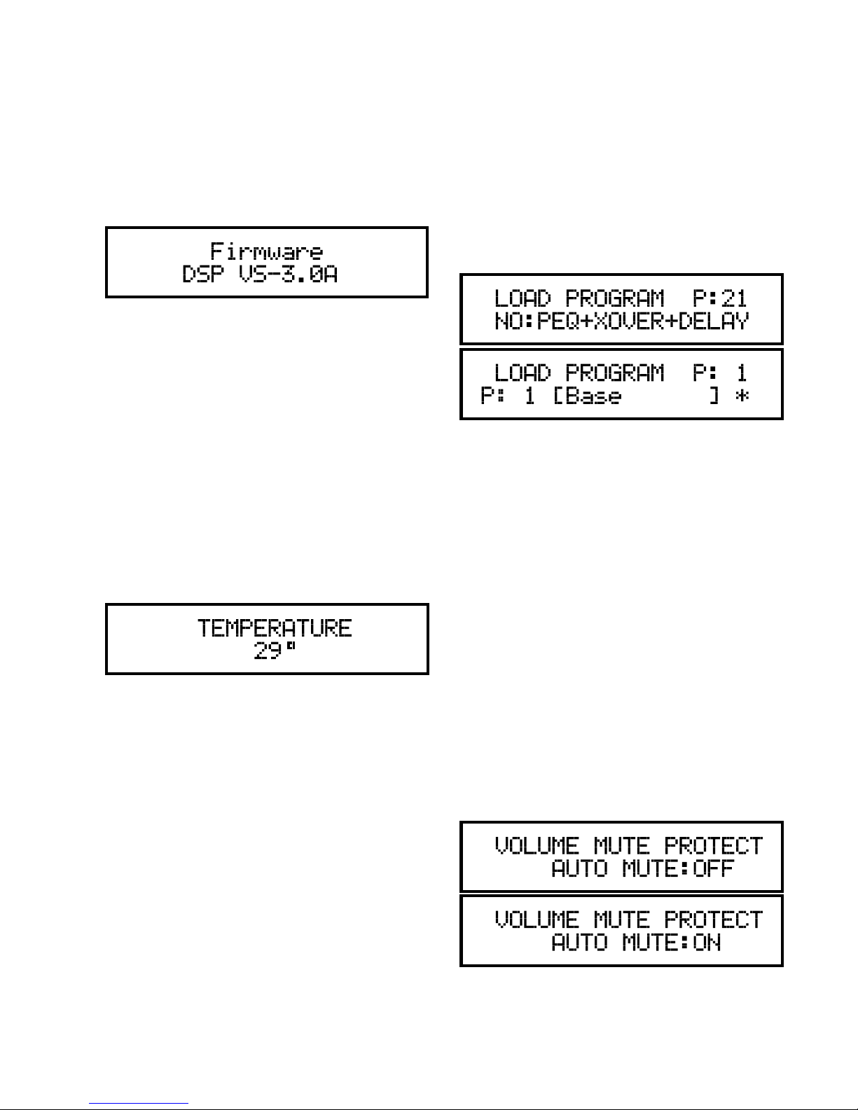
Firmware Installed
To view the firmware version currently
installed in the amplifier enter setup
mode using the CH A encoder. Release
the encoder when FIRMWARE is displayed.
This is an informational screen only and
no changes are permitted.
To change between saved presets enter
setup mode using the CH B encoder.
Release the encoder when LOAD
PROGRAM is displayed. Rotate the
encoder to scroll between PROGRAM 1
and 21. Press and release the encoder to
save the setting and exit setup mode.
• Default setting: P21 (No EQ, Crossover,
Delay or Limiter)
Temperature Indication
To view the operating temperature of the
amplifier enter setup mode using the CH
A encoder. Release the encoder when
TEMPERATURE is displayed. This is an
informational screen only and no changes
are permitted.
To display the temperature reading at all
times simply press and hold the control
for 5 seconds while temperature is
displayed. This display will overide the VU
display.
Load Program
SP amplifiers can store up to 20 user
defined preset configurations. Presets
store all DSP settings, gain settings and
device names to non-volatile memory in
the amplifier. Settings can be recalled by
selecting the appropritae preset.
Volume Mute Protect
This option determines the gain setting
when the amplifier is switched on. When
AUTO MUTE:OFF is selected the amplifier
will revert to the last gain setting before
it was powered down. When AUTO MUTE:
ON is selected the amplifier will start with
both outputs muted.
To change between mute protect settings
enter setup mode using the CH B encoder.
Release the encoder when VOLUME MUTE
PROTECT is displayed. Rotate the encoder
to select between ON and OFF. Press and
release the encoder to save the setting
and exit setup mode.
• Default Setting: Auto Mute: OFF
Page 17
Page 17
SP Series User Manual
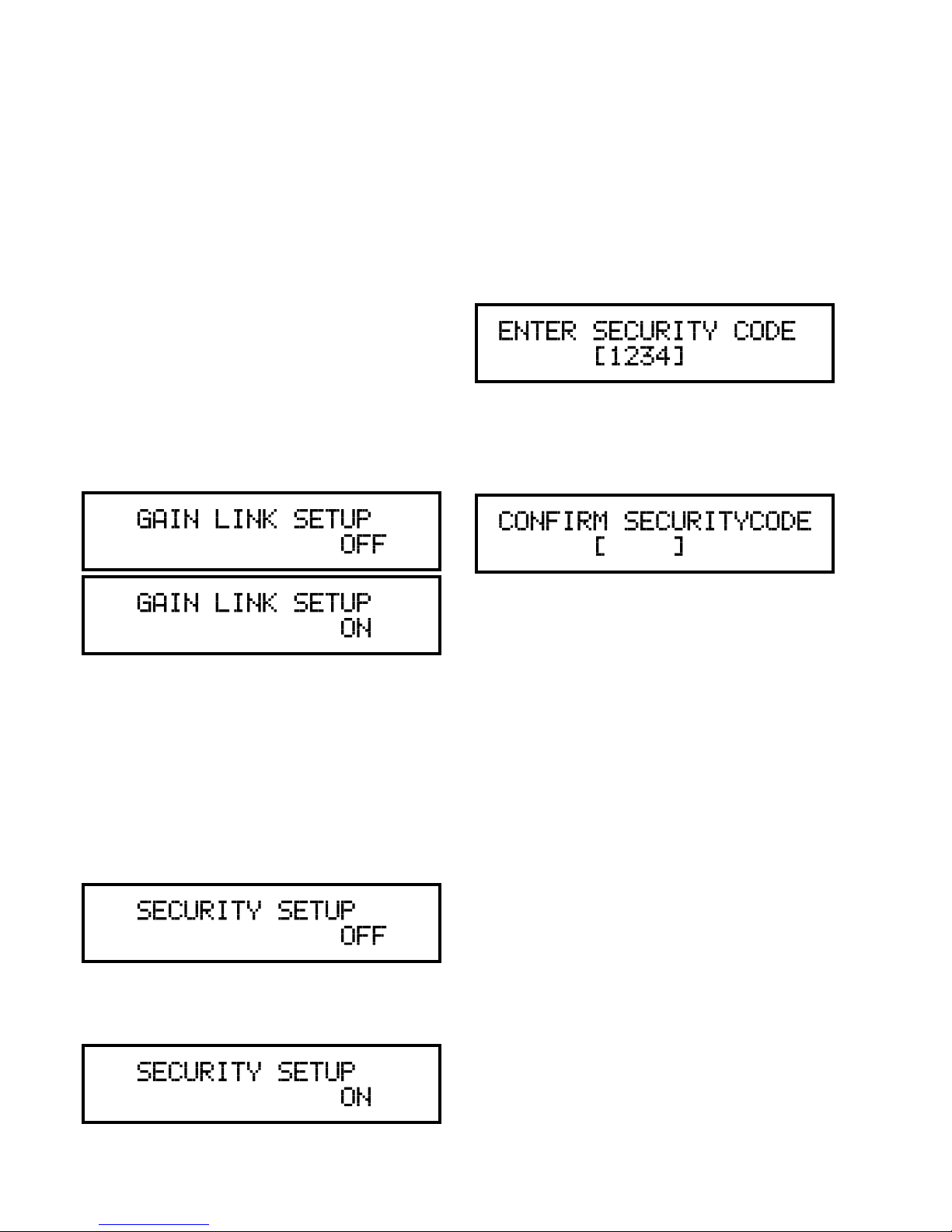
Gain Link
This option links the function of the two
gain controls, allowing both channels to
be adjusted simultaneously by either gain
control. When GAIN LINK is ON, either
gain control will affect both channels.
When the option is OFF, gain controls are
independent.
To change between gain link settings
enter setup mode using the CH B encoder.
Release the encoder whenGAIN LINK
SETUP is displayed. Rotate the encoder
to select between ON and OFF. Press and
release the encoder to save the setting
and exit setup mode.
• Default Setting: OFF
Security
This option allows the user to lock out the
front panel controls preventing tampering
and adjustment.
To lock the controls enter setup mode
using the CH B encoder. Release the
encoder when SECURITY SETUP is
displayed.
Rotate the encoder to select ON. Press
and release the encoder to save the
setting.
The display will prompt you to enter a
four character security code. The code
can include any combination of letters,
numbers and symbols in the system.
Rotate the encoder to display the first
character of the desired security code.
Press to select and advance the prompt
to the next character. Repeat until all four
characters have been selected.
Once all characters have been entered
you will be prompted to confirm the
security code. Repeat the steps outlined
above.
Successful confirmation of the security
code will immediately lock the front panel
controls and exit setup mode.
When security mode is active pressing or
turning the controls will prompt the user
for the security code. Successful entry of
the stored code will unlock the controls.
• Default Setting: OFF
Page 18
Page 18
SP Series User Manual
SP series amplifiers are designed to be
operated continuously in demanding
professional audio applications. To
ensure continued trouble-free operation
make sure that your amplifiers are
properly connected, powered and
protected and that there is sufficient
airflow around them. The following items
are considered good practice and should
be implemented in every installation.
Power
Ensure that each amplifier is connected to
a properly rated power outlet that is fused
for the anticipated load. Do not share
outlets with other devices or appliances
and ensure that the selected AC circuit
does not also feed other outlets or lights.
Where possible, locate the amplifiers
close to the breaker panel or transformer
or ensure that the feeder cables are
sufficiently rated to ensure a minimum of
voltage sag under load.
Grounding
Amplifiers should be properly grounded
to Earth through the building’s electrical
system. It is strongly advised that you
test the actual integrity of the grounding
system in the venue with a proper
electrical tester. Never operate the
amplifier without a proper ground, or
use a two-conductor AC input cable.
Performance will be degraded and a
severe risk of injury or death could be
posed by such operation.
Signal Cables
All input signal cables should be properly
shielded and balanced. While SP series
amplifiers will accept unbalanced signals,
noise performance and signal integrity
will be degraded, especially in areas
of high electro-magnetic fields or near
commercial or consumer transmitters,
computers or networking equipment.
Speaker Cables
Ensure that all speaker cables are sized
correctly for the speakers connected and
the powered being delivered to them.
A large portion of the electrical energy
delivered at the amplifier’s output can be
lost to heat in the speaker cabling, unless
it is sized correctly. Calculating the correct
size of the wire needed requires knowing
the load impedance, the amount of power
to be delivered and the total length of the
speaker run.
Cooling
SP series amplifiers are highly efficient,
converting most of the electrical power
they draw into power at the outputs, and
not heat. Most of the time they are cooled
passively and the internal fan does not
run, but under continued use at higher
power levels the fan will start to ensure
that the amplifier does not overheat.
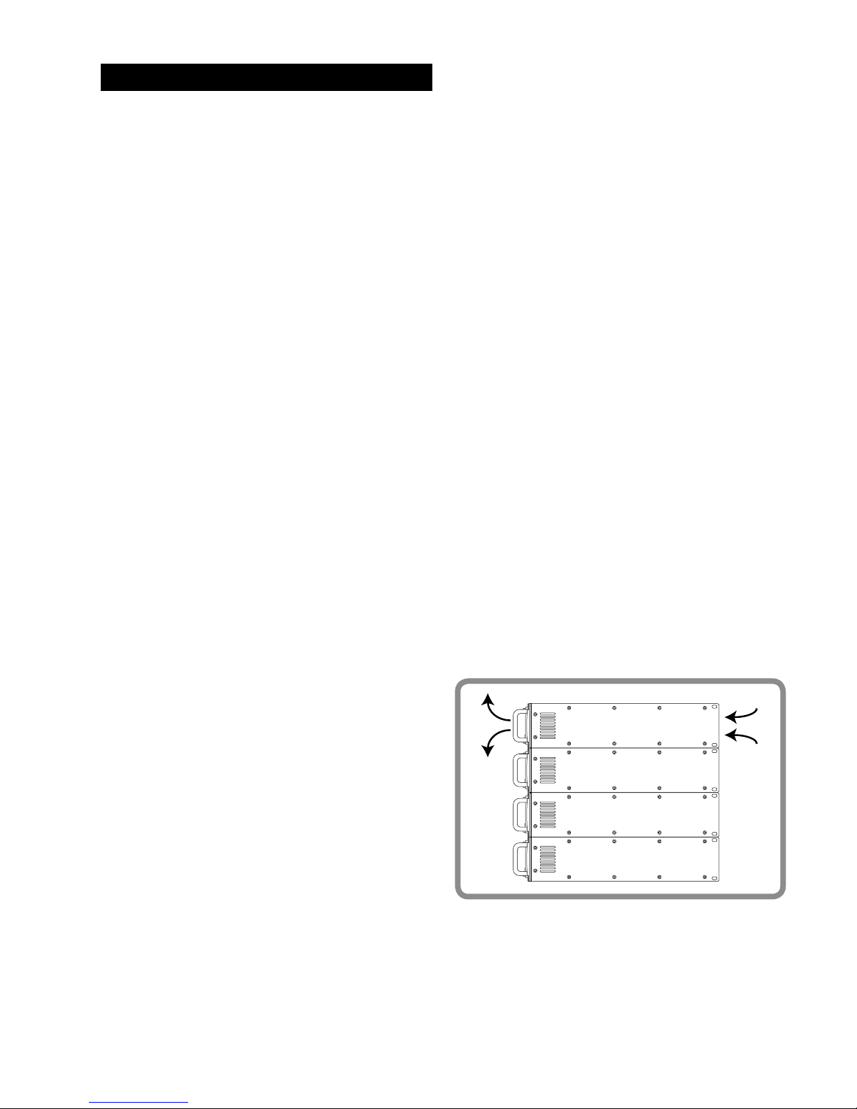
The fan pulls air in from the rear of the
amplifier and expels air from the front.
12. OPERATION
Page 19
Page 19
SP Series User Manual
It is critical that the front and rear air
vents are not obstructed and that the
amplifier is located in a space where there
is sufficient air volume and circulation to
ensure continued cooling.
Avoid installing the amplifiers in a closed
cabinet or a small room without access to
fresh air circulation. Amplifiers mounted
in a rack will require vent panels to be
installed, possibly with supplemental fans
to continually exchange the air inside the
rack. In larger installations supplemental
room cooling may be required to
maintain the ambient temperature within
operational limits.
115
VibeNET
IN OUT
OUTPUTS
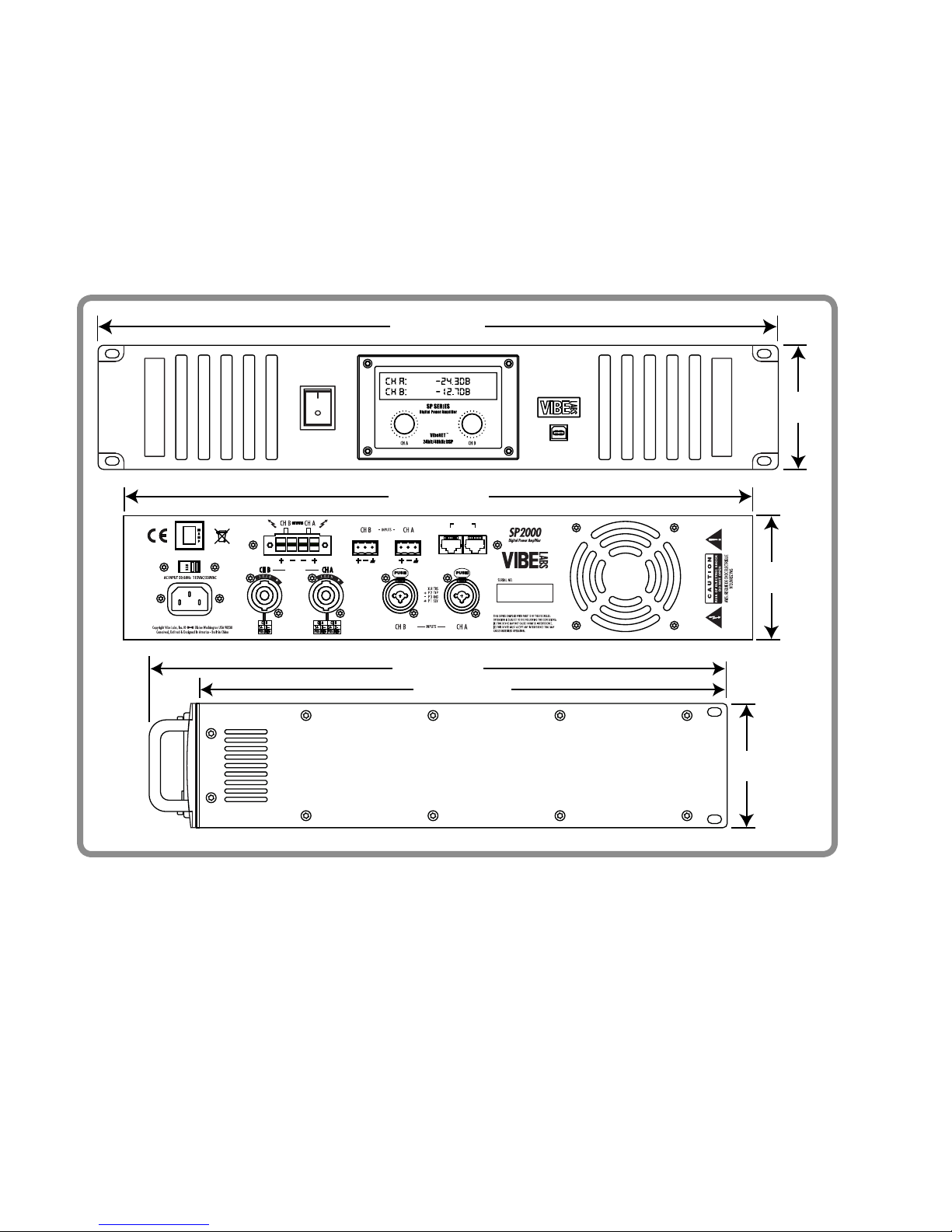
14.7”/375mm
16.2”/412mm
17.1”/435mm
3.5”/
88mm
3.5”/
88mm
3.5”/
88mm
19.0”/482mm
© Copyright 2009, Vibe Labs, Inc.
Vibe Labs™ is a trademark of Vibe Labs, Inc.
All other trademarks used in this manual are the property of their respective owners.
No part of this manual may be copied, reproduced, scanned or posted witout the express
written permission of Vibe Labs, Inc.
Page 20

Vibe Labs, Inc.
250 H Street, #549
Blaine WA 98230
www.vibelabs.com
SP Series User Manual Version B
 Loading...