

Page 1
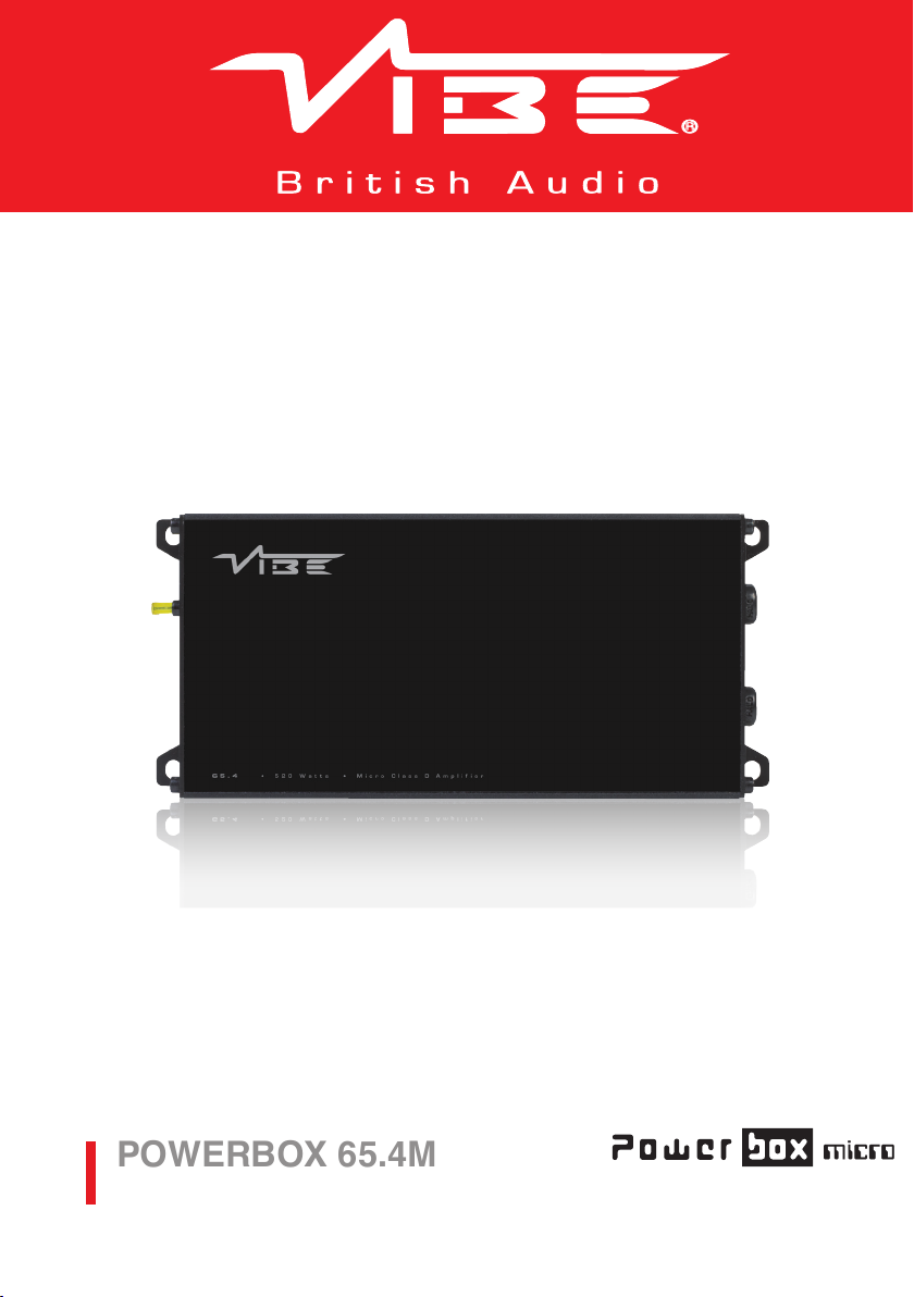
POWERBOX 65.4M
POWERBOX65.4M-V7
micro
Power Amplifiers
Page 2

Owners Manual
Congratulations on purchasing your VIBE amplier. Please read this manual in order
to fully understand how to get the best results from this product and ensure that all
advice on how to look after the product is followed.
Thank you for buying VIBE, we hope you enjoy listening to your product as much as
we enjoyed creating it.
Attention
An aftermarket audio amplier will place an additional load on the vehicles charging
system.
Most modern vehicles have sufcient capacity in the charging system as not all the
electrical components of the vehicle will be switched on at once.
Check the fuse rating of the amplier and use this as the peak current requirement.
Generally the continuous current draw will be a third of the peak current.
2
Warning
During the normal use of this amplier the heatsink may become very hot.
Please do not touch during or immediately after use.
Please ensure that when installing this product the heatsink will not come into contact
with any materials that may be damaged by heat such as upholstery or plastics.
UK Technical Enquiries
Call 09067031420
Calls cost 50p per minute. Call costs correct at date of
publication (01/02/12)
Hours of business 9.00am - 5.30pm GMT Monday - Friday.
All calls are recorded for training purposes.
MIDBASS Distribution
PO Box 11000
B75 7WG
International Technical Enquiries
For international technical support please contact the
distribution agent for your country.
Please visit www.vibeaudio.co.uk/contact for more details.
Page 3

Limited Warranty
All VIBE products carry a full 12 month warranty, valid from the date of the original
receipt and proof of purchase. The online warranty card should be completed within
seven days of the original purchase date. The original receipt and packaging should
be retained for this twelve month period. If the product develops a problem any
stage during the warranty period, it should be returned to the point of purchase in
it’s original packaging, and complete with no items missing. If the store is unable to
repair the product it may have to be returned to VIBE.
A full description of VIBE’s warranty information can be found on our website:
www.vibeaudio.co.uk
What Is Not Covered
• Damage to product due to improper installation.
• Subsequent damage to other components.
• Damage caused by exposure to moisture, excessive heat, chemical cleaners and / or UV
radiation.
• Damage through negligence, misuse, accident or abuse. Repeated returns for the same fault
may be considered abuse.
• Any cost or expense related to the removal and / or re-installation of the product.
• Damage caused by amplier clipping or distortion.
• Items repaired or modied by any unauthorised repair facility.
• Return shipping on non defective items.
• Products returned without a returns authorisation number.
• Damage to product due to use of sealant.
International Warranty
Contact your international VIBE dealer or distributor concerning specic procedure for your
country’s warranty policies. www.vibeaudio.co.uk/warranty
3
Warning
VIBE equipment is capable of sound pressure levels that can cause permanent damage to your
hearing and those around you. Please use common sense when listening to your audio system
and practice safe sound.
Copyright
All content included in this manual such as text, graphics, logos, icons, images and data, are the property of Midbass Distribution Limited t/a VIBE
Technologies Limited (herein referred to as “VIBE”, “us” or “we”) and its afliate or their content and technology providers, and are protected by United
Kingdom and International copyright laws. All rights reserved. VIBE TV, VIBE Arcade, Bass Box, Optisound, Cinesound, BlackAir, BlackBox, Space,
LiteAir, SLICK, BlackDeath, Bubonic, Reaper, Anti-VIBE, FastPlug, BlackHole, QB69, VIBE Turbo Port, Vibe TurboVent, Pressure Board, Super Driver,
VIBE Pulse, VIBE Power, VIBE Digital, VIBE MAG Plugs, Ferrite Loaded, VIBE Solid Core, VIBE OCC, VIBE FLAT, ICC, Bass Enhance, Bass Enhance+,
QBass, SpeedBass, PowerBass, N-Wedge, Box Grip, ARBSS, Supercar Series and all stylised representations of product names, or the abbreviations
of product names, as logos are all trademarks of VIBE. Graphics and logos are trademarks or trade dress of VIBE Technologies Ltd or its subsidiaries.
VIBE’s trademarks and trade dress may not be used in connection with any product or service that is not VIBE’s, in any manner that is likely to cause
confusion among customers or in any manner that disparages or discredits VIBE. All other trademarks not owned by VIBE or its subsidiaries that
appear in this manual are the property of their respective owners, who may or may not be afliated with, connected to, or sponsored by VIBE or its
subsidiaries.
TO THE FULLEST EXTENT PERMITTED AT LAW, VIBE IS PROVIDING THIS MANUAL AND ITS CONTENT ON AN “AS IS” BASIS AND MAKES
NO (AND EXPRESSLY DISCLAIMS ALL) REPRESENTATIONS OR WARRANTIES OF ANY KIND, EXPRESS OR IMPLIED, WITH RESPECT TO THIS
MANUAL OR THE INFORMATION, CONTENT, MATERIALS OR PRODUCTS INCLUDED IN THIS MANUAL INCLUDING, WITHOUT LIMITATION,
WARRANTIES OF MERCHANTABILITY AND FITNESS FOR A PARTICULAR PURPOSE. IN ADDITION, VIBE DOES NOT REPRESENT OR WARRANT
THAT THE INFORMATION CONTAINED IN THIS MANUAL IS COMPLETE OR CURRENT, AND THAT ALL SPECIFICATIONS AND INFORMATION
CONTAINED WITHIN THIS MANUAL ARE SUBJECT TO CHANGE WITHOUT NOTICE. VIBE RECOMMEND CAUTION WHEN LISTENING TO MUSIC
REPRODUCED THROUGH VIBE EQUIPMENT. VIBE EQUIPMENT IS CAPABLE OF PRODUCING SOUND AND SOUND PRESSURE LEVELS THAT
CAN PERMANENTLY DAMAGE HEARING OF YOU AND THAT OF OTHERS. FOR SAFE AND ENJOYABLE LISTENING, THE SOUND SHOULD BE
CLEAR WITHOUT DISTORTION AT A COMFORTABLE VOLUME. BY USING ANY VIBE EQUIPMENT, YOU AGREE TO TAKE FULL RESPONSIBILITY
FOR YOUR OWN SAFETY AND THE SAFETY OF OTHERS WHEN LISTENING TO MUSIC AT HIGH VOLUMES THROUGH EQUIPMENT YOU HAVE
PURCHASED. USE OF ANY VIBE EQUIPMENT CONSTITUTES AGREEMENT TO THIS DISCLAIMER. Except as specically stated in this manual, to the
fullest extent permitted at law, neither VIBE nor any of its afliates, directors, employees or other representatives will be liable for damages arising out
of or in connection with the use of this manual or the information, content, materials or products included. This is a comprehensive limitation of liability
that applies to all damages of any kind, including (without limitation) compensatory, direct, indirect or consequential damages, loss of data, income or
prot, loss of or damage to property and claims of third parties. For the avoidance of doubt, VIBE does not limit its liability for death or personal injury to
the extent only that it arises as a result of negligence of VIBE, its afliates, directors, employees or other representatives.
Page 4
Mounting Guidelines
Your VIBE amplier is designed with a swift installation routine in mind.
Please mount the amplier in a dry location on a solid surface.
NEVER mount the amplier upside down as this will cause the amplier to over heat and
will eventually damage the amplier.
Before xing the amplier in place please ensure that there is sufcient air ow around
the exterior of the casing, at least two inches is sufcient to allow effective cooling.
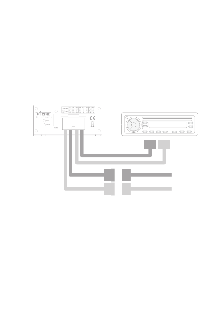
Power / Speaker Connections
To Headunit
4
Vehicle ISO Loom
NOTE : If your vehicle does not have a standard ISO connector (for example a quadlock
connector) it will be necessary to purchase a separate vehicle specic T-Harness
connector
Contact your local VIBE dealer for more information.
Page 5

5
Power Cable
• If not using the vehicles ISO cable, at least 12 gauge cable should be used for the power
connection to the amplier.
• The power cable should be taken directly from the battery. Rubber grommets should be
used when passing through any bulkheads to prevent the cable from becoming chaffed
or cut.
• It is vital that a fuse / circuit breaker (of at least equal value to the one tted in the
amplier) is placed inline with the power cable and is no further than 18 inches away
from the battery.
• Please ensure that the fuse is not tted until the entire installation procedure is complete.
Ground Cable
• If not using the vehicles ISO cable, at least 12 gauge cable should be used for the
ground connection to the amplier.
• The amplier ground should be connected directly to the chassis of the vehicle, to
bare metal.
• The cable length should be kept to an absolute minimum.
• It is not recommended that you connect the ground cable to the vehicles seatbelts
anchor point.
Auto Turn On (High level Input Only)
• The PowerBox ampliers feature an auto turn on circuit called Autosense.
• This circuit allows the amplier to switch on and off without a remote turn on wire
when using high level input, for low level input (RCA) it will still be necessary to
connect the remote turn on wire from the headunit.
• When the connected source (headunit) is turned on the amplier will turn on
automatically, after the connected source (headunit) is turned off the amplier will
shut down.
RCA Cables
• Depending on the model of your headunit and the number of speakers you
wish to power you will have to run either one, two or three RCA cables from the
source to the amplier.
• Please take extra care when running these cables from the source to the amplier.
Ensure that they are placed away from all items that can generate any interference,
wiring harnesses etc.
• It is recommended that the RCA cables should be run on opposite sides of the car
to the previously installed power cables if possible, to avoid the cable picking up
interference.
Page 6
1 2 3 4 5 6 87 9
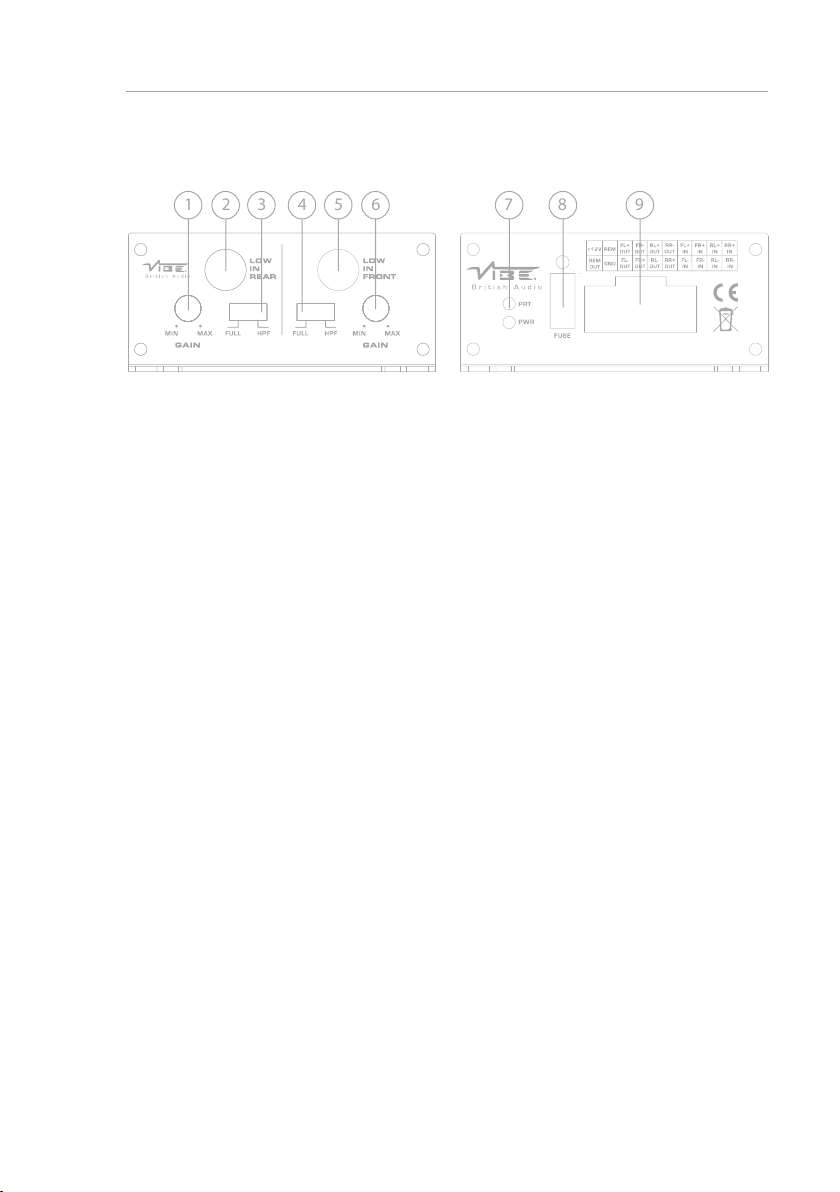
Terminals And Connections
1. Rear gain control
This control is used to match the input signal of the source to the rear channels of the
amplier. See the setup section for more details.
2. Rear low level input / output
For connection to any source (head unit) with a low level output to the rear channels of
the amplier. This is your RCA output from the source (headunit). Additionally, if using
high level input this RCA lead provides an output can be used to connect an additional
amplier or audio device.
3. Rear crossover mode select switch
This control is used to select the crossover mode of the rear channels of the amplier.
FULL is for full range output, HPF is used to limit the amount of low frequency information
passed to the speakers and is xed at 80Hz.
4. Front crossover mode select switch
This control is used to select the crossover mode of the rear channels of the amplier.
FULL is for full range output, HPF is used to limit the amount of low frequency information
passed to the speakers and is xed at 80Hz.
5. Front low level input / output
For connection to any source (head unit) with a low level output to the rear channels of
the amplier. This is your RCA output from the source (headunit). Additionally, if using
high level input this RCA lead provides an output can be used to connect an additional
amplier or audio device.
6. Rear gain control
This control is used to match the input signal of the source to the rear channels of the
amplier. See the setup section for more details.
7. Power / protect LED
If the amplier is operating normally, the GREEN LED will illuminate.
If the amplier is in protection mode the RED LED will illuminate.
8. Fuse
Replace with only the same value ATC fuse : 20A
9. Power / speaker terminals
Used to connect DC power and speaker input / output cables to the amplier. See the
wiring conguration section for more details
6
Page 7

Set Up Section
To correctly set the gain control of the amplier to match that of the source (headunit) use the
following setup routine:
• Turn the gain control to minimum on the amplier.
• Ensure the bass boost on the headunt is set to 0 dB.
• Set all crossovers on the headunt ( if applicable) to at and both bass and treble to zero.
• Turn up the source (headunit) to approx 3/4 volume.
• Very slowly turn up the gain on the amplier until distortion can be heard in any of the
speakers or until the volume reaches an uncomfortable listening level when this is reached turn
the gain control down slightly.
The gain control is now set.
The setting of the crossover will depend on what kind of speaker you are installing.
Note: The smaller the speaker, the less bass it can handle, so for a larger speaker FULL would be
preferred, and HPF for a smaller speaker..
By using the crossovers correctly you will not only lengthen the life of your speakers but you will also
get better performance from them.
To optimise your setup seek the advise of a professional installation engineer or visit your local VIBE
audio dealer.
7
Specication
Model POWERBOX65.4M-V7
Configuration 4 channel
Dimensions (H x W x D)
RMS @ 4Ω Stereo 4 x 65 watts
RMS @ 2Ω Stereo N/A
RMS @ 4Ω Mono N/A
Maximum Power 520 watts
Recommended Fuse 20 Amps
Frequency Response 20Hz - 20kHz
Crossover Type HP / Full
Crossover Range 80Hz
Topology Class D
1.5” x 7.4” x 3.2”
(37mm x 187mm x 82mm)
Page 8
Designed and engineered in England
www.vibeaudio.co.uk
www.youtube.com/vibeaudio
www.facebook.com/vibeaudio
www.twitter.com/vibeaudio
www.vibeaudio.co.uk
www.youtube.com/vibeaudio
www.facebook.com/vibeaudio
www.twitter.com/vibeaudio
Designed and engineered in England
www.vibeaudio.co.uk
www.vibeaudio.co.uk
www.youtube.com/vibeaudio
www.youtube.com/vibeaudio
www.facebook.com/vibeaudio
www.facebook.com/vibeaudio
www.twitter.com/vibecaraudio
www.twitter.com/vibecaraudio
micro
 Loading...