

Page 1

CT-4
Digital Leakage Tagger
User’s Guide
Page 2

Notice
Every effort was made to ensure that the information in this manual was accurate at the time
of printing. However, information is subject to change without notice, and VIAVI reserves the
right to provide an addendum to this manual with information not available at the time that this
manual was created.
Copyright/Trademarks
© Copyright 2018 VIAVI Solutions Inc. All rights reserved. No part of this guide may be
reproduced or transmitted, electronically or otherwise, without written permission of the
publisher. VIAVI Solutions and the VIAVI logo are trademarks of VIAVI Solutions Inc. (“Viavi”).
All other trademarks and registered trademarks are the property of their respective owners.
Copyright release
Reproduction and distribution of this guide is authorized for US Government purposes only.
Ordering information
This guide is a product of VIAVI Technical Publications Department, issued as part of the
product. The catalog number for a published guide is Catalog Number - printed. The catalog
number for an electronic guide on USB is Catalog Number - electronic.
Terms and conditions
Specications, terms, and conditions are subject to change without notice. The provision
of hardware, services, and/or software are subject to VIAVI standard terms and conditions,
available at www.viavisolutions.com/en/terms-and-conditions.
CT-4 User’s Guide
Document Num., Rev. 5 May 2018Page 2
Page 3

Table of Contents
Chapter 1
General Information ..................................................................................................................5
Ordering Information ..............................................................................................................5
Where to Get Technical Support ............................................................................................5
How this Manual is Organized ...............................................................................................6
Conventions Used in this Manual...........................................................................................7
Precautions ............................................................................................................................7
Periodic Calibration ................................................................................................................7
Chapter 2
Introduction ................................................................................................................................9
What is the CT-4? ..................................................................................................................9
CT-2/3 Operation ..............................................................................................................9
CT-2/3 Application...........................................................................................................10
CT-4 Operation ...............................................................................................................10
CT-4 Application.............................................................................................................. 11
Equipment Supplied with Your CT-4.....................................................................................11
Accessories & Replacement Parts for Your CT-4.................................................................11
A Guided Tour of Your CT-4 .................................................................................................12
Front View .......................................................................................................................12
Rear View .......................................................................................................................13
Display Screen Navigation..............................................................................................14
Chapter 3
Installation ................................................................................................................................21
Overview ..............................................................................................................................21
Installation Instructions.........................................................................................................22
CT-2 Operation ...............................................................................................................22
CT-3 Operation ...............................................................................................................23
CT-4 Operation ...............................................................................................................23
CT-4 User’s Guide
Document Num., Rev. 5May 2018 Page 3
Page 4

Chapter 4
Setup .........................................................................................................................................25
Setup Guidelines ..................................................................................................................25
Leakage Receiver Tag Detection Support ......................................................................25
Tag Modulation Settings .................................................................................................26
CT-2 Operation Mode Setup ................................................................................................27
CT-3 Operation Mode Setup ................................................................................................28
CT-4 Operation Mode Setup ................................................................................................30
Example Setup Using a Spectrum Analyzer ...................................................................33
Typical Spectrum Analyzers ......................................................................................33
Advanced Spectrum Analyzers .................................................................................34
Example CT-4 Setup Scenarios......................................................................................35
All Analog (Low Band) & All Digital (High Band) Adjacent Carriers ...........................35
Mixed (Low Band) & All Digital (High Band) Adjacent Carriers .................................36
All Digital (Low Band) & All Digital (High Band) Adjacent Carriers ............................ 38
Mixed Digital (Low & High Band) Adjacent Carriers ..................................................39
Single Adjacent Carriers ............................................................................................40
No Adjacent Carriers .................................................................................................41
CT-3 Tech Setup ..................................................................................................................42
Ethernet Setup .....................................................................................................................43
CT Security Setup ................................................................................................................44
Chapter 5
Appendix ..................................................................................................................................45
General Specications .........................................................................................................45
CT-2 Operation Mode Specications ...................................................................................45
CT-3 Operation Mode Specications ...................................................................................46
CT-4 Operation Mode Specications ...................................................................................47
CT-4 Error Codes .................................................................................................................48
Limited Warranty ..................................................................................................................49
CT-4 User’s Guide
Document Num., Rev. 5 May 2018Page 4
Page 5

Chapter 1
General Information
Ordering Information
For additional information about our products and services, contact your local VIAVI
representative or visit https://www.viavisolutions.com/en-us/how-buy.
Where to Get Technical Support
Phone US: +1-844-GO-VIAVI or +1-844-468-4284
Outside US: +1-855-275-5378
Email: Trilithic.support@viavisolutions.com
Website: https://support.viavisolutions.com/welcome
CT-4 User’s Guide
Document Num., Rev. 5May 2018 Page 5
Page 6

How this Manual is Organized
This manual is divided into the following chapters:
• Chapter 1, “General Information” provides contact information and describes how this
operation manual is structured.
• Chapter 2, “Introduction” introduces what the CT-4 is and what it does. This chapter
discusses the practical application, connections and controls of the CT-4.
• Chapter 3, “Installation” describes steps needed to install the CT-4.
• Chapter 4, “Setup” describes the steps needed to perform initial conguration of the
CT-4 and describes the sreps needed to perform periodic calibration of the CT-4.
• Chapter 5, “Appendix” shows the technical specications of the CT-4.
CT-4 User’s Guide
Document Num., Rev. 5 May 2018Page 6
Page 7
Conventions Used in this Manual
This manual has several standardized conventions for presenting information:
• Connections, menus, menu options, and user-entered text and commands appear in
bold.
• Section names, web, and e-mail addresses appear in italics.
A NOTE is information that will be of assistance to you related
to the current step or procedure.
A CAUTION alerts you to any condition that could cause a
mechanical failure or potential loss of data.
A WARNING alerts you to any condition that could cause
personal injury.
Precautions
Do not use the CT-4 in any manner not recommended by the
manufacturer
The CT-4 may not operate correctly in the presence of a
strong electromagnetic eld.
Periodic Calibration
The chosen frequency must closely match that of the leakage detector or leaks will not be
detected properly. If the CT-4 appears to be out of calibration, the unit must be returned to
VIAVI or a VIAVI authorized repair center for re-calibration.
CT-4 User’s Guide
Document Num., Rev. 5May 2018 Page 7
Page 8

CT-4 User’s Guide
Document Num., Rev. 5 May 2018Page 8
Page 9

Chapter 2
Introduction
This chapter:
• Describes the purpose of the CT-4
• Gives a feature overview of the CT-4
• Lists the equipment supplied with the CT-4 and optional accessories
• Gives a guided tour of the CT-4 and explains the display screen
What is the CT-4?
The CT-4 is a 1U rack mounted unit that is located in the headend that provides an
uncompromising tagging solution for active analog or digital systems.
CT-2/3 Operation
The new CT-4 can act as a traditional CT-2 or CT-3 analog tagger. This feature provides
the ability to detect tagged leaks and ignore untagged leaks, saving time from false alarms
from signals not originating in your system.
When several CATV systems operate in the same area, it is often difcult to determine
which system is the source of a detected leak. The CT-4 is designed to deal with the
problem of leakage identication in dual cable or overbuilt situations.
The CT-4 solves the problem of determining which cable is leaking by attaching a low
frequency tag to the analog leakage carrier on the cable system.
VIAVI leakage receivers with analog tag detection including the Searcher Plus GT, Super
Plus, Seeker Lite², Seeker and Seeker SE can be set to alarm only when the leakage signal
has been tagged to insure the leak is from your system. The tagged signal from the CT-4
also causes a distinctive audible response in these leakage receivers.
VIAVI leakage receivers generate an audible tone that varies in pitch depending on the
leakage strength. When the CT-4 tags a leak, it causes this audible tone to rise and fall in
pitch at a rate of:
• 3 Hz – This is a “warble” tone that is used primarily with the Searcher Plus, Searcher
Plus GT, or Super Plus analog leakage detectors. If you do not hear this uctuating
tone, you know that the leak did not originate in your system.
• 10 to 23 Hz (excluding 16 Hz) – This is the tag frequency that is used with the
Searcher Plus GT, Super Plus, Seeker Lite², Seeker and Seeker SE leakage
detectors.
CT-4 User’s Guide
Document Num., Rev. 5May 2018 Page 9
Page 10

CT-2/3 Application
Used as a system with a VIAVI leakage receiver, the CT-4 helps to eliminate “false alarm”
triggers. The CT-2 and CT-3 provide the following features:
• Tags carrier used for traditional analog leakage measurement for easy identication.
• Provides low frequency modulation (3 Hz) “warble” tone for use with the Searcher
Plus, Searcher Plus GT, or Super Plus analog leakage detectors.
• Provides higher frequency modulation (10 to 23 Hz, excluding 16 Hz) tag for use
with the Super Plus, Search Lite, Seeker Lite², Seeker and Seeker SE leakage
detectors.
• Provides a built-in leakage carrier source and is non interfering because its low
frequency modulation is removed easily by the customer’s TV automatic gain
control.
CT-4 Operation
The new CT-4™ works in conjunction with the Seeker D and Seeker D Lite Digital Leakage
Detectors. The VIAVI Seeker D leakage detector accurately detects and measures signal
leakage within the LTE and aeronautical frequency bands and features unsurpassed
sensitivity from 2 to 2000 uV/m (20 to 2000 uV/m for Seeker D Lite).
The Seeker D and Seeker D Lite detect the proprietary signals from the CT-4 and scale the
leakage value to match the adjacent analog or digital carrier as programmed into the meter.
If reference analog is selected in the Seeker D, the readings will closely resemble the
readings from an analog Seeker measuring leakage off the adjacent analog carrier.
Whether testing for leaks in both digital and analog systems, or monitoring aeronautical
bands or LTE, the Seeker D and Seeker D Lite provide all of the capability to nd and x
leaks quickly, accurately, and effectively.
CT-4 User’s Guide
Document Num., Rev. 5 May 2018Page 10
Page 11
CT-4 Application
Used as a system with the Seeker D and Seeker D Lite Digital Leakage Detectors, the CT-4
detects leaks in the Aeronautical and LTE frequency bands and eliminates all “false alarm”
triggers. The CT-4 provides the following features:
• Provides proprietary dual CW carriers to give the Seeker D and Seeker D Lite
Leakage Detectors the ability to detect leaks in the Aeronautical Frequency Band
(135–139 MHz) and provides immunity to “false alarms”.
• Provides proprietary dual CW carriers to give the Seeker D and Seeker D Lite
Leakage Detectors the ability to detect leaks in the LTE Frequency Band (610.5–615
MHz) and provides immunity to “false alarms”.
• The CT-4 eliminates the risk of affecting any adjacent digital channels by injecting
an adjustable signal from 10 to 30 dBmV, targeting approximately 30 dB below the
chosen digital carriers.
Equipment Supplied with Your CT-4
The CT-4 comes with the following:
• CT-4 Digital Leakage Tagger
• AC U.S. Power Cable
• Operation manual on CD
Accessories & Replacement Parts for Your CT-4
The following replacement parts are available for the CT-4:
Part Number Description
0190197000
0190322000
To place an order, contact your local VIAVI representative, call 1-844-GO-VIAVI, or visit
https://www.viavisolutions.com/en-us/how-buy.
AC U.S. Power Cable
6 Foot Male (NEMA 5-15P) to Female (IEC 320C13)
AC Euro Power Cable
2.5 Meter Male (IEC 884/CEE 7/VII) to Female (IEC 320C13)
CT-4 User’s Guide
Document Num., Rev. 5May 2018 Page 11
Page 12
A Guided Tour of Your CT-4
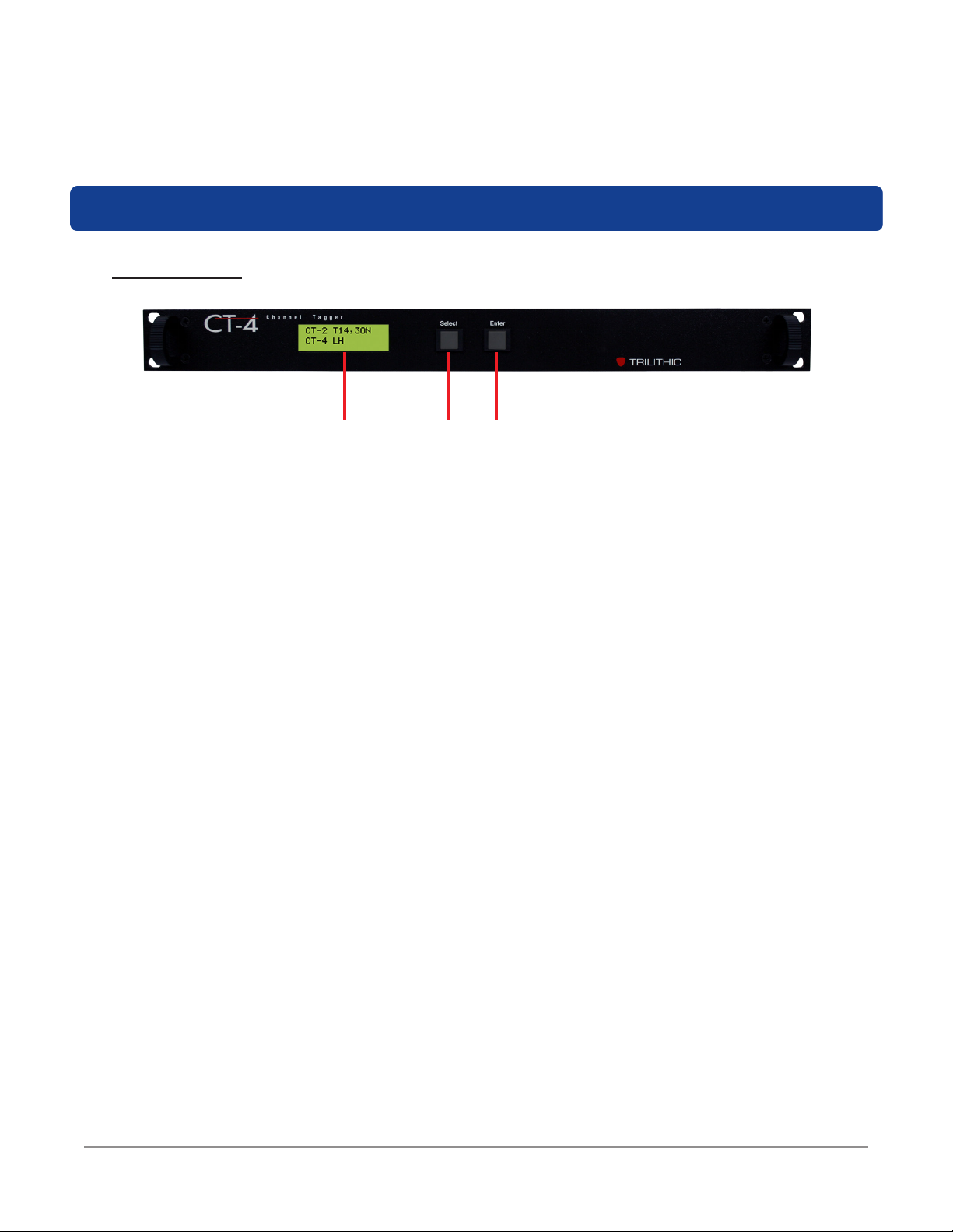
Front View
1 2 3
1. Display Screen – This LCD is used to display the setup and operational status of the
CT-4. The setup information on most screens can be adjusted from the front panel of
the device.
2. Select – This button is used to control the CT-4 as follows:
• Scroll through the main menus
• Scroll through the setup/display options available within the selected sub-menu
• Adjust the settings within individual setup options after the Enter button has been
selected.
3. Enter – This button is used to control the CT-4 as follows:
• Enter the menus and sub-menus
• Select individual setup options to adjust settings
CT-4 User’s Guide
Document Num., Rev. 5 May 2018Page 12
Page 13
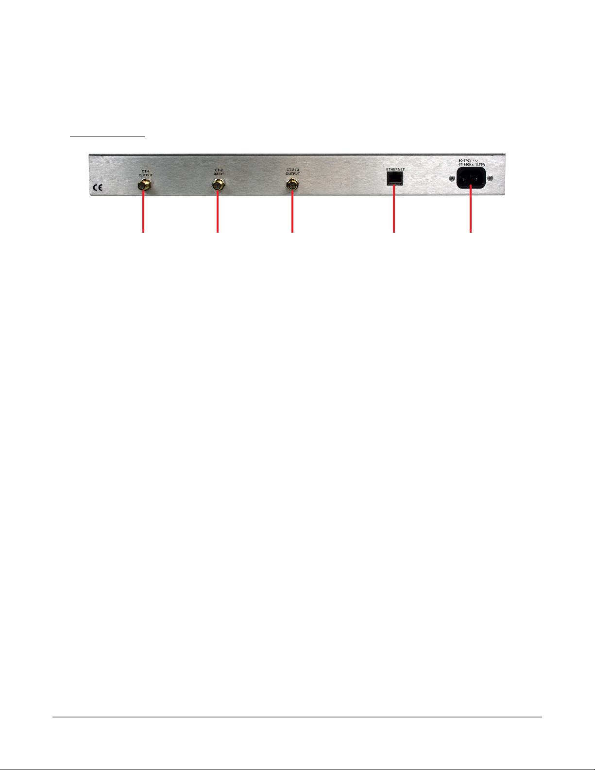
Rear View
1 2 3 4 5
1. CT-4 Output – This is the RF output connection for the CT-4 function.
2. CT-2 Input – This is the RF input connection for the CT-2 function.
3. CT-2/3 Output – This is the RF output connection for the CT-2/3 function.
4. Ethernet – This port is for factory use and rmware upgrades.
5. AC Power Input – This is a Female (IEC 320C13) port for connection of an AC power
cable. This port accepts AC input power from 90 to 370 VAC (47-440 Hz), 0.75 A.
CT-4 User’s Guide
Document Num., Rev. 5May 2018 Page 13
Page 14
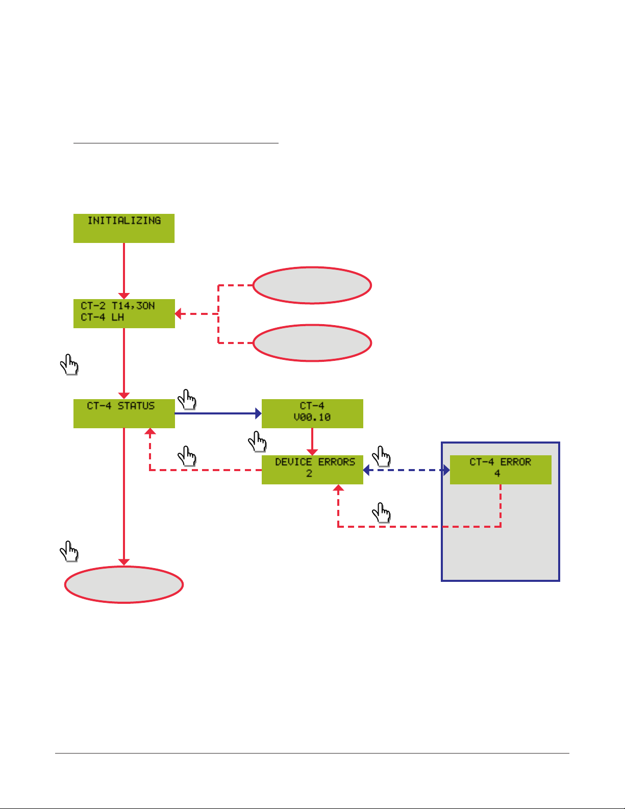
Display Screen Navigation
The following images provide an example of the method used to navigate the menus
available on the CT-4 display screen.
Upon Startup this Screen Appears
for Approximately 10 Seconds
FROM
CT SECURITY
HOME SCREEN
INACTIVITY
TIMEOUT
Select
Enter
Select
TO
CT-4 SETUP
Select
Select
Enter
Select
ONLY AVAILABLE
WHEN ERRORS
EXIST
CT-4 User’s Guide
Document Num., Rev. 5 May 2018Page 14
Page 15
FROM
CT-4 STATUS
Select
Enter
Select
TO ADJUST
SETTINGS
Enter
Select
Enter
Select
Enter
Select
Enter
Select
Enter
Select
TO
CT-3 SETUP
Select
Select
Enter
Select
Enter
Select
Enter
Select
Enter
CT-4 User’s Guide
Document Num., Rev. 5May 2018 Page 15
Page 16

FROM
CT-4 SETUP
Select
Enter
Select
TO ADJUST
SETTINGS
Enter
Select
Enter
Select
Enter
Select
Enter
Select
Enter
Select
TO
CT-3 TECH SETUP
Select
Select
Select
ONLY AVAILABLE
Select
Select
CT-4 User’s Guide
Document Num., Rev. 5 May 2018Page 16
Enter
WHEN
SELECT = CT-3
Enter
Enter
Page 17

FROM
CT-4 SETUP
Select
TO
ETHERNET STATUS
Enter
Select
Select
TO ADJUST
SETTINGS
Enter
Select
Enter
CT-4 User’s Guide
Document Num., Rev. 5May 2018 Page 17
Page 18

FROM
CT-3 TECH SETUP
Select
Enter
Select
TO ADJUST
SETTINGS
Enter
Select
Enter
Select
Enter
Select
Enter
Select
Enter
Select
TO
CT SECURITY
Select
Select
Select
Select
CT-4 User’s Guide
Document Num., Rev. 5 May 2018Page 18
Enter
ONLY AVAILABLE
WHEN
USING = STATIC
Enter
Enter
LOADS DEFAULT
SETTINGS
Page 19

FROM
CT-4 SETUP
Select
Enter
Enter
TO
HOME SCREEN
Select
Select
Enter
LOADS DEFAULT
SETTINGS
Enter
Enter
LOADS DEFAULT
SETTINGS
CT-4 User’s Guide
Document Num., Rev. 5May 2018 Page 19
Page 20

CT-4 User’s Guide
Document Num., Rev. 5 May 2018Page 20
Page 21

Chapter 3
Installation
Overview
The CT-4 needs to be installed where it can be injected into the system to reach the customer
base at the frequency ranges that are specied by the desired mode(s) of operation;
• CT-2 Operation
• 10 to 23 Hz (excluding 16 Hz) Tag
• Carrier Source: External Channel Modulator Input
• Carrier Frequency Band: Determined by External Channel Modulator
• CT-3 Operation
• 10 to 23 Hz (excluding 16 Hz) Tag
• Carrier Source: Integrated CW Source Output
• Carrier Frequency Band: 107–157.5 MHz
• CT-4 Operation
• Carrier Source: Integrated Proprietary Dual CW Source Output
• Aeronautical Carrier Frequency Band (Low Band): 135–139 MHz
• LTE Carrier Frequency Band (High Band): 610.5–615 MHz
108.0 MHz
FM RADIO
97.25 MHz
AERONAUTICAL
RADIONAVIGATION
103.25 MHz
109.25 MHz
115.25 MHz
117.975 MHz
AERONAUTICAL
MOBILE
BROADCAST SPECTRUM
121.25 MHz
Band Carrier
(136 to 139 MHz)
127.25 MHz
CT-4 Low
137 MHz
632 MHz
638 MHz
FIXED & MOBILE
NON-TACTICAL COMMUNICATIONS
133.25 MHz
139.25 MHz
145.25 MHz
151.25 MHz
157.25 MHz
163.25 MHz
169.25 MHz
596 MHz
DTV35DTV
594 MHz
Band Carrier
(610.5 to 615 MHz)
602 MHz
36
BROADCAST SPECTRUM
600 MHz
606 MHz
CT-4 High
608 MHz
Radio
Astronomy
612 MHz
614 MHz
620 MHz
DTV38DTV
618 MHz
39
626 MHz
624 MHz
630 MHz
96 97 98 99 14 15 16 17 18
MIDBAND CABLE CHANNELS
CT-3 Carrier
(107.0 to 157.5 MHz)
CT-4 User’s Guide
Document Num., Rev. 5May 2018 Page 21
19 20 21
86 87 88 89 90 91
DIGITAL CABLE CHANNELS
Page 22

Installation Instructions
Typically a CT-4 should be installed at each location that an existing CT-2 or CT-3 is installed
and in many cases this may require a CT-4 to be installed in each hub site and/or each head
end.
The following section explains the procedure used to install the CT-4. In order to properly setup
the CT-4 the following steps must be completed in this order. Do not skip any steps.
Be sure to verify the whether the AC line voltage is correct for
the device or damage may occur.
CT-2 Operation
For operation in the CT-2 mode, perform the following installation steps;
1. Select a suitable rack panel location near the modulator for the desired leakage
channel and mount the CT-4 in the rack using four retaining screws.
2. Connect the device between the modulator and combiner as shown in the image
below.
3. Connect the device to AC power.
IN OUT
MODULATOR
COMBINER
CT-4 User’s Guide
Document Num., Rev. 5 May 2018Page 22
Page 23

CT-3 Operation
For operation in the CT-3 mode, perform the following installation steps;
1. Select a suitable rack panel location near the combiner where RF signals reside and
mount the CT-4 in the rack using four retaining screws.
2. Connect the device to the combiner as shown in the image below.
3. Connect the device to AC power.
OUT
COMBINER
CT-4 Operation
For operation in the CT-4 mode, perform the following installation steps;
1. Select a suitable rack panel location near the combiner where RF signals reside and
mount the CT-4 in the rack using four retaining screws.
2. Connect the device to the combiner as shown in the image below.
3. Connect the device to AC power.
OUT
COMBINER
CT-4 User’s Guide
Document Num., Rev. 5May 2018 Page 23
Page 24

CT-4 User’s Guide
Document Num., Rev. 5 May 2018Page 24
Page 25

Chapter 4
Setup
Setup Guidelines
Leakage Receiver Tag Detection Support
The following VIAVI leakage detectors DO NOT include tag detection:
• Searcher Plus
• Single detection frequency of 108 to 157.25 MHz
• Crystal controlled xed frequency, set at the factory
The following VIAVI leakage detectors include CT-2 or CT-3 type tag detection in the
corresponding frequency ranges:
• Super Plus & Searcher Plus GT
• Single detection frequency of 108 to 157.25 MHz
• Crystal controlled and set at the factory
• Default modulation of 20 Hz, internally adjustable & set at the factory
• Seeker Lite²
• Frequency range of 118.5 to 147.25 MHz
• Default detection frequencies of 121.2625, 127.2625, 133.2625, 139.2500
& 146.2625 MHz, user congurable in 6.25 kHz steps using optional Seeker
Setup software
• Modulation range of 10 to 23 Hz (excluding 16 Hz)
• Default modulation of 20 Hz, user congurable in 1 Hz steps using optional
Seeker Setup software
• Seeker & Seeker SE
• Low band frequency range of 109.25 to 110.5 MHz (models marked “LOW
BAND ENABLED”)
• High band frequency range of 118.5 to 147.25 MHz (all models)
• Default detection frequencies of 121.2625, 127.2625, 133.2625, 139.2500
& 146.2625 MHz, user congurable in 6.25 kHz steps using optional Seeker
Setup software
• Default modulation of 20 Hz, user congurable in 1 Hz steps using optional
Seeker Setup software
CT-4 User’s Guide
Document Num., Rev. 5May 2018 Page 25
Page 26

The following VIAVI leakage detectors include CT-4 type tag detection:
• Seeker D & Seeker D Lite
• Low band frequency range of 135 to 139 MHz
• High band frequency range of 610.5 to 615 MHz
• Low & high bands are user congurable in 12.5 kHz steps using optional
Seeker Setup software
Tag Modulation Settings
Use the following modulation settings for the leakage tag depending on the type(s) of VIAVI
leakage receivers you will be using in your system:
• Receivers Without Tag Detection – Use the 3 Hz setting to enable a “warble” tone
to be heard on leakage meters that do not use channel tagging.
• Receivers With Tag Detection – Use the 10 to 23 Hz (excluding 16 Hz) setting to
match the modulation settings of the leakage receivers in your system.
The 3 Hz “warble” tone can be used simultaneously with the
10 to 23 Hz (excluding 16 Hz) for a mix of receivers with and
without tag detection. However, the Seeker products will not
benet from the use of the 3 Hz “warble” tone, since they
utilize the 10 to 23 Hz (excluding 16 Hz) tag signal.
The modulation settings only apply to the use of the CT-2/3
operation mode. The CT-4 operation mode for the Seeker D
and Seeker D Lite digital leakage detectors does not use a
modulated signal.
CT-4 User’s Guide
Document Num., Rev. 5 May 2018Page 26
Page 27

CT-2 Operation Mode Setup
In the CT-2 operation mode, an external channel modulator is required to produce a channel
that the CT-4 tag will be combined with. The CT-4 will generate a tag with 10 to 23 Hz
(excluding 16 Hz) modulation that will be combined internally with the channel provided by the
external channel modulator.
Perform the following steps to properly setup the CT-2 operation mode:
1. From the front panel of the CT-4, navigate to the CT-3 SETUP
menu.
2. From this menu, navigate to the CT-2/3 DEVICE menu.
3. From this menu, enable the device by selecting the ON option.
4. Navigate to the SELECT menu and select the CT-2 option.
5. Perform the following actions depending on whether your system includes:
RECEIVERS WITH TAG DETECTION OR
RECEIVERS WITH & WITHOUT TAG DETECTION
• Navigate to the 3HZ TAG ENABLE menu and select the
OFF option to ensure that this feature doesn’t interfere
with the channel tag.
• Navigate to the TAG FREQ menu and enter the channel
tag frequency modulation in MHz that matches the
modulation settings of the leakage receivers you will be
using in your system.
• Navigate to the TAG ENABLE menu and select the ON
option to enable channel tagging for supported devices.
CT-4 User’s Guide
Document Num., Rev. 5May 2018 Page 27
Page 28

RECEIVERS WITHOUT TAG DETECTION
• Navigate to the TAG ENABLE menu and select the OFF
option to ensure that this feature doesn’t interfere with
the “warble” tone.
• Navigate to the 3HZ TAG DEPTH menu and enter the
tag depth in dB that works best within your system. By
default, the tag depth is set to 3.0 dB, but in some cases
you may desire less than 3 Hz modulation.
• Navigate to the 3HZ TAG ENABLE menu and select
the ON option to enable the “warble” tone for supported
devices.
6. Once the previous steps are completed the CT-2 tag will be enabled and properly
functioning.
CT-3 Operation Mode Setup
In the CT-3 operation mode, the CT-4 injects a tag with 10 to 23 Hz (excluding 16 Hz)
modulation into a frequency agile CW carrier from 107 to 157.5 MHz.
Perform the following steps to properly setup the CT-3 operation mode:
1. From the front panel of the CT-4, navigate to the CT-3 SETUP
menu.
2. From this menu, navigate to the CT-2/3 DEVICE menu.
3. From this menu, enable the device by selecting the ON option.
4. Navigate to the SELECT menu and select the CT-3 option.
CT-4 User’s Guide
Document Num., Rev. 5 May 2018Page 28
Page 29

5. Perform the following actions depending on whether your system includes:
RECEIVERS WITH TAG DETECTION OR
RECEIVERS WITH & WITHOUT TAG DETECTION
• Navigate to the 3HZ TAG ENABLE menu and select the
OFF option to ensure that this feature doesn’t interfere
with the channel tag.
• Navigate to the TAG FREQ menu and enter the channel
tag frequency modulation in MHz that matches the
modulation settings of the leakage receivers you will be
using in your system.
• Navigate to the CT-3 FREQUENCY menu and enter the
channel tag carrier frequency in MHz that matches the
frequency settings of the leakage receivers you will be
using in your system.
• Navigate to the CT-3 LEVEL menu and enter the
channel tag carrier level in dBmV. Adjust the carrier
level to be 1.5 dB below the adjacent video carrier level.
This compensates for the video/cw peak detector efciency of the leakage
receiver.
• Navigate to the TAG ENABLE menu and select the ON
option to enable channel tagging for supported devices.
RECEIVERS WITHOUT TAG DETECTION
• Navigate to the TAG ENABLE menu and select the OFF
option to ensure that this feature doesn’t interfere with
the “warble” tone.
• Navigate to the 3HZ TAG DEPTH menu and enter the
tag depth in dB that works best within your system. By
default, the tag depth is set to 3.0 dB, but in some cases
you may desire less than 3 Hz modulation.
• Navigate to the 3HZ TAG ENABLE menu and select
the ON option to enable the “warble” tone for supported
devices.
6. Once the previous steps are completed the CT-3 tag will be enabled and properly
functioning.
CT-4 User’s Guide
Document Num., Rev. 5May 2018 Page 29
Page 30

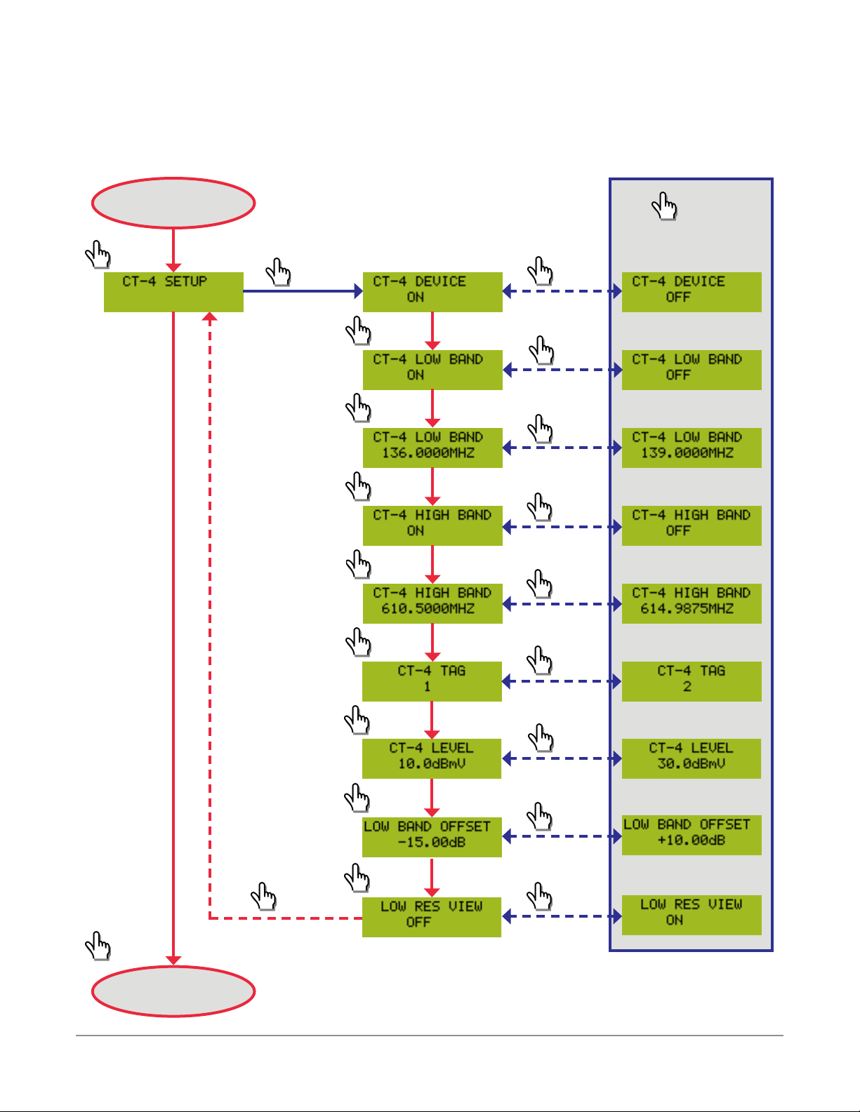
CT-4 Operation Mode Setup
In the CT-4 operation mode, the CT-4 injects proprietary dual CW carrier tags with either
156.25 or 625 Hz spacing between the carriers in the Aeronautical frequency (135 to 139 MHz)
and/or LTE frequency (610.5 to 615 MHz) bands.
Each frequency band can be independently enabled which provides the ability to monitor both
bands simultaneously or each one individually.
When using a standard SCTE channel lineup, we recommended the two pairs of leakage
carriers be injected into the system at 138 MHz and 612 MHz, which is the guard band
between QAMs or analog carriers based on which type of channel resides at each frequency.
If you are not using a standard SCTE channel lineup, the two carriers should be injected in the
guard band between QAMs or analog carriers based on which type of channel resides at each
frequency.
Perform the following steps to properly set up the CT-4 operation mode:
1. Connect a spectrum analyzer to the test port of the combiner that the plant RF and the
CT-4 output are connected to.
2. From the front panel of the CT-4, navigate to the CT-4 SETUP
menu.
3. From this menu, navigate to the CT-4 DEVICE menu.
4. From this menu, enable the device by selecting the ON option.
5. Navigate to the CT-4 LOW BAND menu and select the ON option.
6. Navigate to the CT-4 LOW BAND frequency menu and enter the
channel tag carrier frequency in MHz that matches the low band
frequency settings of the Seeker D and Seeker D Lite leakage
detectors you will be using in your system.
7. Navigate to the CT-4 HIGH BAND menu and select the ON option.
8. Navigate to the CT-4 HIGH BAND frequency menu and enter the
channel tag carrier frequency in MHz that matches the high band
frequency settings of the Seeker D and Seeker D Lite leakage
detectors you will be using in your system.
CT-4 User’s Guide
Document Num., Rev. 5 May 2018Page 30
Page 31

9. Navigate to the CT-4 TAG menu and select spacing between each pair of dual carriers
that matches the settings of the Seeker D and Seeker D Lite leakage detectors you will
be using in your system:
• Select the 1 option to set the spacing between each pair of
dual carriers to 156.25 Hz.
• Select the 2 option to set the spacing between each pair of
dual carriers to 625 Hz.
• Select the 3 option to set the spacing between each pair of dual carriers to 312.5
Hz.
• Select the 4 option to set the spacing between each pair of dual carriers to
468.75 Hz.
• Select the 5 option to set the spacing between each pair of dual carriers to
781.25 Hz.
• Select the 6 option to set the spacing between each pair of dual carriers to 937.5
Hz.
• Select the 7 option to set the spacing between each pair of dual carriers to
1093.75 Hz.
• Select the 8 option to set the spacing between each pair of dual carriers to 1250
Hz.
10. Navigate to the LOW RES VIEW menu.
• Select the ON option to be able to accurately adjust the
output level of the CT-4 using a standard spectrum analyzer
with a minimum resolution bandwidth of 10 kHz.
• Select the OFF option to be able to accurately adjust the
output level of the CT-4 using a high-resolution spectrum
analyzer with a minimum resolution bandwidth of 30 Hz.
11. Navigate to the CT-4 LEVEL menu and enter the high band
channel tag carrier level in dBmV. Using the spectrum analyzer,
adjust the high band carrier level to be 30 dB down from the total
average power of an adjacent QAM carrier or 36 dB down from an
adjacent analog video carrier.
CT-4 User’s Guide
Document Num., Rev. 5May 2018 Page 31
Page 32

12. Navigate to the LOW BAND OFFSET menu and enter the low
band offset in dB. Using the spectrum analyzer, adjust the low band
carrier level to be 30 dB down from the level of an adjacent QAM
carrier or 36 dB down from an adjacent analog carrier.
13. Navigate to the LOW RES VIEW menu and select the OFF option
to enable normal operation.
14. Once the previous steps are completed the CT-4 tags will be enabled and properly
functioning.
CT-4 User’s Guide
Document Num., Rev. 5 May 2018Page 32
Page 33

Example Setup Using a Spectrum Analyzer
The signal displays and settings shown in this section are
for reference only and performance may vary based on
manufacturer/model of analyzer.
Typical Spectrum Analyzers
The screens shown in this section represent the view a typical Spectrum Analyzer with a
minimum resolution bandwidth of 10 kHz would provide when setting up the CT-4.
We recommend using an Advanced Spectrum Analyzer for the
initial setup of the CT-4. However, a typical spectrum analyzer
can be used for setup as shown below.
• When the Low Resolution Mode
(Setup Mode) of the CT-4 is turned
OFF, one of 8 tags is used between
the carriers which will not allow you to
distinguish between each peak of the
CT-4 carrier as shown in the image to
the right.
If only 2 tags are available, a rmware update is available.
Contact us at Trilithic.support@viavisolutions.com or
1-844-GO-VIAVI.
CT-4 User’s Guide
Document Num., Rev. 5May 2018 Page 33
Page 34

• When the Low Resolution Mode
(Setup Mode) of the CT-4 is turned
ON, a 25 kHz spacing is used
between the carriers. This will allow
you to distinguish between each
peak of the CT-4 carrier as shown
Level
in the image to the right. This is an
CT-4
acceptable spectrum analyzer view for
initial setup and provides the minimum
accuracy needed for CT-4 carrier level
measurement.
Advanced Spectrum Analyzers
With an advanced spectrum analyzer, the Low Resolution Mode (Setup Mode) of the
CT-4 should be turned OFF. The screen shown below represents the display of an
Advanced Spectrum Analyzer with the following recommended settings:
• Resolution Bandwidth (RBW) of 30 Hz.
• Video Bandwidth (VBW) of 30 Hz.
• Frequency Span of 1 kHz.
Level
CT-4
CT-4 User’s Guide
Document Num., Rev. 5 May 2018Page 34
Page 35

Example CT-4 Setup Scenarios
All Analog (Low Band) & All Digital (High Band) Adjacent Carriers
HIGH BAND - 612 MHz
Channel 88
(QAM 64/256)
1. Measure & Record the Average Total Power of
both Adjacent Carriers
CH 88 = _____ dBmV CH 89 = _____ dBmV
2. Use the lowest Average Total Power of the two
adjacent carriers to Calculate the Target CT-4
High Band Carrier Level.
Target CT-4 Level = P
Target CT-4 Level = _____ - 30 dB
Target CT-4 Level = _____ dBmV
3. Measure CT-4 High Band Carrier Level
Channel 89
(QAM 64/256)
- 30 dB
MIN
LOW BAND - 138 MHz
Channel 16
(ANALOG)
1. Measure & Record the Peak Video Level of both
Adjacent Carriers
CH 16 = _____ dBmV CH 17 = _____ dBmV
2. Use the lowest Video Level of the two adjacent
carriers to Calculate the Target CT-4 Low Band
Carrier Level.
Target CT-4 Level = L
Target CT-4 Level = _____ - 36 dB
Target CT-4 Level = _____ dBmV
3. Measure CT-4 Low Band Carrier Level
Channel 17
(ANALOG)
- 36 dB
MIN
Level
4. Adjust the CT-4 LEVEL (Front Panel) upward
from its minimum value until:
Actual CT-4 Level = Target CT-4 Level
Actual CT-4 Level = _____ dBmV
5. Record CT-4 Carrier Level (Front Panel)
CT-4 Level = _____ dBmV
Document Num., Rev. 5May 2018 Page 35
Level
4. Adjust the LOW BAND OFFSET (Front Panel)
upward from its minimum value until:
Actual CT-4 Level = Target CT-4 Level
Actual CT-4 Level = _____ dBmV
5. Record Low Band Offset Value (Front Panel)
LOW BAND OFFSET = _____ dBmV
CT-4 User’s Guide
Page 36

Mixed (Low Band) & All Digital (High Band) Adjacent Carriers
HIGH BAND - 612 MHz
Channel 88
(QAM 64/256)
1. Measure & Record the Average Total Power of
both Adjacent Carriers
CH 88 = _____ dBmV CH 89 = _____ dBmV
2. Use the lowest Average Total Power of the two
adjacent carriers to Calculate the Target CT-4
High Band Carrier Level.
Target CT-4 Level = P
Target CT-4 Level = _____ - 30 dB
Target CT-4 Level = _____ dBmV
3. Measure CT-4 High Band Carrier Level
Channel 89
(QAM 64/256)
- 30 dB
MIN
LOW BAND - 138 MHz
Channel 16
(ANALOG)
1. Measure & Record the Average Total Power of
CH 17
CH 17 = _____ dBmV
2. Use the Average Total Power of the adjacent
Digital Carrier (CH 17) to Calculate the Target
CT-4 Low Band Carrier Level.
Target CT-4 Level = P
Target CT-4 Level = _____ - 30 dB
Target CT-4 Level = _____ dBmV
3. Measure CT-4 Low Band Carrier Level
Channel 17
(QAM 64/256)
- 30 dB
ADJ
Level
4. Adjust the CT-4 LEVEL (Front Panel) upward
from its minimum value until:
Actual CT-4 Level = Target CT-4 Level
Actual CT-4 Level = _____ dBmV
5. Record CT-4 Carrier Level (Front Panel)
CT-4 Level = _____ dBmV
Document Num., Rev. 5 May 2018Page 36
Level
4. Adjust the LOW BAND OFFSET (Front Panel)
upward from its minimum value until:
Actual CT-4 Level = Target CT-4 Level
Actual CT-4 Level = _____ dBmV
5. Record Low Band Offset Value (Front Panel)
LOW BAND OFFSET = _____ dBmV
CT-4 User’s Guide
Page 37

HIGH BAND - 612 MHz
LOW BAND - 138 MHz
Channel 88
(QAM 64/256)
Channel 89
(QAM 64/256)
1. Measure & Record the Average Total Power of
both Adjacent Carriers
CH 88 = _____ dBmV CH 89 = _____ dBmV
2. Use the lowest Average Total Power of the two
adjacent carriers to Calculate the Target CT-4
High Band Carrier Level.
Target CT-4 Level = P
- 30 dB
MIN
Target CT-4 Level = _____ - 30 dB
Target CT-4 Level = _____ dBmV
3. Measure CT-4 High Band Carrier Level
Channel 16
(QAM 64/256)
Channel 17
(ANALOG)
1. Measure & Record the Average Total Power of
CH 16
CH 16 = _____ dBmV
2. Use the Average Total Power of the adjacent
Digital Carrier (CH 16) to Calculate the Target
CT-4 Low Band Carrier Level.
Target CT-4 Level = P
- 30 dB
ADJ
Target CT-4 Level = _____ - 30 dB
Target CT-4 Level = _____ dBmV
3. Measure CT-4 Low Band Carrier Level
Level
4. Adjust the CT-4 LEVEL (Front Panel) upward
from its minimum value until:
Actual CT-4 Level = Target CT-4 Level
Actual CT-4 Level = _____ dBmV
5. Record CT-4 Carrier Level (Front Panel)
CT-4 Level = _____ dBmV
Document Num., Rev. 5May 2018 Page 37
Level
4. Adjust the LOW BAND OFFSET (Front Panel)
upward from its minimum value until:
Actual CT-4 Level = Target CT-4 Level
Actual CT-4 Level = _____ dBmV
5. Record Low Band Offset Value (Front Panel)
LOW BAND OFFSET = _____ dBmV
CT-4 User’s Guide
Page 38

All Digital (Low Band) & All Digital (High Band) Adjacent Carriers
HIGH BAND - 612 MHz
Channel 88
(QAM 64/256)
1. Measure & Record the Average Total Power of
both Adjacent Carriers
CH 88 = _____ dBmV CH 89 = _____ dBmV
2. Use the lowest Average Total Power of the two
adjacent carriers to Calculate the Target CT-4
High Band Carrier Level.
Target CT-4 Level = P
Target CT-4 Level = _____ - 30 dB
Target CT-4 Level = _____ dBmV
3. Measure CT-4 High Band Carrier Level
Channel 89
(QAM 64/256)
- 30 dB
MIN
LOW BAND - 138 MHz
Channel 16
(QAM 64/256)
1. Measure & Record the Average Total Power of
both Adjacent Carriers
CH 16 = _____ dBmV CH 17 = _____ dBmV
2. Use the lowest Average Total Power of the two
adjacent carriers to Calculate the Target CT-4
High Band Carrier Level.
Target CT-4 Level = P
Target CT-4 Level = _____ - 30 dB
Target CT-4 Level = _____ dBmV
3. Measure CT-4 Low Band Carrier Level
Channel 17
(QAM 64/256)
- 30 dB
MIN
Level
4. Adjust the CT-4 LEVEL (Front Panel) upward
from its minimum value until:
Actual CT-4 Level = Target CT-4 Level
Actual CT-4 Level = _____ dBmV
5. Record CT-4 Carrier Level (Front Panel)
CT-4 Level = _____ dBmV
Document Num., Rev. 5 May 2018Page 38
Level
4. Adjust the LOW BAND OFFSET (Front Panel)
upward from its minimum value until:
Actual CT-4 Level = Target CT-4 Level
Actual CT-4 Level = _____ dBmV
5. Record Low Band Offset Value (Front Panel)
LOW BAND OFFSET = _____ dBmV
CT-4 User’s Guide
Page 39

Mixed Digital (Low & High Band) Adjacent Carriers
HIGH BAND - 612 MHz LOW BAND - 138 MHz
Channel 88
(QAM 256)
1. Measure & Record the Average Total Power of
both Adjacent Carriers
CH 88 = _____ dBmV CH 89 = _____ dBmV
2. Use the lowest Average Total Power of the two
adjacent carriers to Calculate the Target CT-4
High Band Carrier Level.
Target CT-4 Level = P
Target CT-4 Level = _____ - 30 dB
Target CT-4 Level = _____ dBmV
3. Measure CT-4 High Band Carrier Level
Channel 89
(QAM 64)
- 30 dB
MIN
Channel 16
(QAM 64)
1. Measure & Record the Average Total Power of
both Adjacent Carriers
CH 16 = _____ dBmV CH 17 = _____ dBmV
2. Use the lowest Average Total Power of the two
adjacent carriers to Calculate the Target CT-4
High Band Carrier Level.
Target CT-4 Level = P
Target CT-4 Level = _____ - 30 dB
Target CT-4 Level = _____ dBmV
3. Measure CT-4 Low Band Carrier Level
Channel 17
(QAM 256)
- 30 dB
MIN
Level
4. Adjust the CT-4 LEVEL (Front Panel) upward
from its minimum value until:
Actual CT-4 Level = Target CT-4 Level
Actual CT-4 Level = _____ dBmV
5. Record CT-4 Carrier Level (Front Panel)
CT-4 Level = _____ dBmV
Document Num., Rev. 5May 2018 Page 39
Level
4. Adjust the LOW BAND OFFSET (Front Panel)
upward from its minimum value until:
Actual CT-4 Level = Target CT-4 Level
Actual CT-4 Level = _____ dBmV
5. Record Low Band Offset Value (Front Panel)
LOW BAND OFFSET = _____ dBmV
CT-4 User’s Guide
Page 40

Single Adjacent Carriers
HIGH BAND - 612 MHz LOW BAND - 138 MHz
Channel 88
(QAM 64/256)
1. Measure & Record the Average Total Power of
the Adjacent Carrier
CH 88 = _____ dBmV
2. Use the Average Total Power of the adjacent
carrier to Calculate the Target CT-4
High Band Carrier Level.
Target CT-4 Level = P
Target CT-4 Level = _____ - 30 dB
Target CT-4 Level = _____ dBmV
3. Measure CT-4 High Band Carrier Level
Channel 89
(No Carrier)
- 30 dB
ADJ
Channel 16
(No Carrier)
1. Measure & Record the Average Total Power of
the Adjacent Carrier
CH 17 = _____ dBmV
2. Use the Average Total Power of the adjacent
carrier to Calculate the Target CT-4
High Band Carrier Level.
Target CT-4 Level = P
Target CT-4 Level = _____ - 30 dB
Target CT-4 Level = _____ dBmV
3. Measure CT-4 Low Band Carrier Level
Channel 17
(QAM 64/256)
- 30 dB
ADJ
Level
4. Adjust the CT-4 LEVEL (Front Panel) upward
from its minimum value until:
Actual CT-4 Level = Target CT-4 Level
Actual CT-4 Level = _____ dBmV
5. Record CT-4 Carrier Level (Front Panel)
CT-4 Level = _____ dBmV
Document Num., Rev. 5 May 2018Page 40
Level
4. Adjust the LOW BAND OFFSET (Front Panel)
upward from its minimum value until:
Actual CT-4 Level = Target CT-4 Level
Actual CT-4 Level = _____ dBmV
5. Record Low Band Offset Value (Front Panel)
LOW BAND OFFSET = _____ dBmV
CT-4 User’s Guide
Page 41

No Adjacent Carriers
HIGH BAND - 612 MHz LOW BAND - 138 MHz
Channel 15 / 87
(QAM 64/256)
1. Measure & Record the Average Total Power of
the nearest Adjacent Carriers
CH 87 = _____ dBmV CH 90 = _____ dBmV
2. Use the lowest Average Total Power of the two
adjacent carriers to Calculate the Target CT-4
High Band Carrier Level.
Target CT-4 Level = P
Target CT-4 Level = _____ - 30 dB
Target CT-4 Level = _____ dBmV
3. Measure CT-4 High Band Carrier Level
Channel 16 / 88
(No Carrier)
- 30 dB
MIN
Channel 17 / 89
(No Carrier)
1. Measure & Record the Average Total Power of
the nearest Adjacent Carriers
CH 15 = _____ dBmV CH 18 = _____ dBmV
2. Use the lowest Average Total Power of the two
adjacent carriers to Calculate the Target CT-4
High Band Carrier Level.
Target CT-4 Level = P
Target CT-4 Level = _____ - 30 dB
Target CT-4 Level = _____ dBmV
3. Measure CT-4 Low Band Carrier Level
Channel 18 / 90
(QAM 64/256)
- 30 dB
MIN
Level
4. Adjust the CT-4 LEVEL (Front Panel) upward
from its minimum value until:
Actual CT-4 Level = Target CT-4 Level
Actual CT-4 Level = _____ dBmV
5. Record CT-4 Carrier Level (Front Panel)
CT-4 Level = _____ dBmV
Document Num., Rev. 5May 2018 Page 41
Level
4. Adjust the LOW BAND OFFSET (Front Panel)
upward from its minimum value until:
Actual CT-4 Level = Target CT-4 Level
Actual CT-4 Level = _____ dBmV
5. Record Low Band Offset Value (Front Panel)
LOW BAND OFFSET = _____ dBmV
CT-4 User’s Guide
Page 42

CT-3 Tech Setup
The CT-3 TECH SETUP menu is used to set whether users are allowed to enable/disable the
tags from the CT-4 web interface. However, the CT-4 web interface is not available at this time.
Once it becomes available the settings within this menu will apply to anyone who logs in with a
TECH level account.
Perform the following steps to properly setup the CT-3 Tech Setup:
1. Navigate to the CT-3 TECH SETUP menu.
2. Navigate to the TAG ENABLE menu and select from either of the
following options:
• TURN ON – If the tag is off, this will turn on the channel tag
for 30 seconds.
• LEAVE OFF – If the tag is off, this will leave the channel tag
off.
• TURN OFF – If the tag is on, this will turn off the channel tag
for 30 seconds.
• LEAVE ON – If the tag is on, this will leave the channel tag
on.
3. Navigate to the 3HZ TAG ENABLE menu and select from either of the following options:
• TURN ON – If the 3 Hz tag is off, this will turn on the channel
tag for 30 seconds.
• LEAVE OFF – If the 3 Hz tag is off, this will leave the
channel tag off.
• TURN OFF – If the 3 Hz tag is on, this will turn off the
channel tag for 30 seconds.
• LEAVE ON – If the 3 Hz tag is on, this will leave the channel
tag on.
CT-4 User’s Guide
Document Num., Rev. 5 May 2018Page 42
Page 43

Ethernet Setup
The ETHERNET STATUS menu is used to adjust the Ethernet settings of the CT-4. The
Ethernet settings of the CT-4 are used to provide access the CT-4 web interface. However, the
CT-4 web interface is not available at this time. Once it becomes available, the settings within
this menu will allow the CT-4 to be accessible via a network connection.
Perform the following steps to properly setup the CT-3 Tech Setup:
1. Navigate to the ETHERNET STATUS menu.
2. Navigate to the USING DHCP/STATIC menu and select from either
of the following options:
• USING DHCP – This will allow the Ethernet settings of the
CT-4 to be automatically set by a DHCP server.
• USING STATIC – This will allow the Ethernet settings of the
CT-4 to be manually set by the user.
3. If USING DHCP is selected, you can continue navigating through the Ethernet settings
screens to view the network information that is assigned by the DHCP server.
4. If USING STATIC is selected, you can adjust the following Ethernet settings:
• IP – Enter the IP Address from this menu.
• SUBNET – Enter the Subnet Address from this menu.
• GATEWAY – Enter the Gateway Address from this menu.
• DNS1 – Enter the Primary DNS Address from this menu.
• DNS2 – Enter the Secondary DNS Address from this menu.
5. Navigate to the MAC ADDRESS screen to view the MAC Address
of the CT-4.
CT-4 User’s Guide
Document Num., Rev. 5May 2018 Page 43
Page 44

6. Navigate to the LOAD FACTORY DEFAULTS? menu to restore the default Ethernet
settings of the CT-4.
• From this menu, press the Select button to display the
VERIFY LOAD DEFAULTS? menu.
• To load the default Ethernet settings, press the Select button
again.
CT Security Setup
The CT-3 SECURITY menu is used to reset the username and password of the TECH and
ADMIN user accounts for the CT-4 web interface. However, the CT-4 web interface is not
available at this time.
Perform the following steps to reset the user passwords of the CT-4:
1. Navigate to the CT-3 SECURITY menu.
2. Navigate to the LOAD ADMIN DEFAULT? menu.
• From this menu, press the Select button to display the VERIFY LOAD
DEFAULT? menu.
• To load the default Admin password, press the Select button again.
• The default Admin password will be set to “admin”.
3. Navigate to the LOAD TECH DEFAULT? menu.
• From this menu, press the Select button to display the VERIFY LOAD
DEFAULT? menu.
• To load the default Tech password, press the Select button again.
• The default Tech password will be set to “tech”.
CT-4 User’s Guide
Document Num., Rev. 5 May 2018Page 44
Page 45

General Specifications
Chapter 5
Appendix
Input / Output
Impedance
Controls Front Panel Select & Enter Buttons
Display Two-Line LCD, 16 Characters per Line
Communication 10/100 Base-T Ethernet (for factory use only)
Power 90 to 370 VAC, 47-440 Hz, 0.75 A
Size 1U (1.75”) Rack Enclosure
Operating
Temperature
75 Ω (nominal)
50 to 104 °F (10 to 40 °C)
CT-2 Operation Mode Specifications
Compatibility
Modulation Type Sine Wave
Tag Modulation
Frequency
3 Hz Tag Depth of
Modulation
Input Return Loss > 15 db from 100 to 160 MHz
Output Return
Loss
Searcher Plus, Searcher Plus GT, Super Plus, Seeker Lite², Seeker
& Seeker SE Leakage Detectors
3 Hz Warble Tone
10 to 20 Hz (excluding 16 Hz)
0.0 to 3.0 dB
> 13 db from 100 to 160 MHz
CT-4 User’s Guide
Document Num., Rev. 5May 2018 Page 45
Page 46

CT-3 Operation Mode Specifications
Compatibility
Carrier Type Sine Wave
Tag Modulation
Frequency
3 Hz Tag Depth of
Modulation
Carrier Frequency
Carrier Output
Level
Spurious Outputs -60 dBc Minimum
Output Return
Loss
Searcher Plus GT, Super Plus, Seeker Lite², Seeker & Seeker SE
Leakage Detectors
3 Hz Warble Tone, ±0.1 Hz
10 to 20 Hz (excluding 16 Hz), ±0.1 Hz
0.0 to 3.0 dB, ±0.2 dB
107.0000 to 157.5000 MHz, ±2.5 ppm
Adjustable in 3.125 kHz Steps
40.00 to 60.00 dBmV, ±2 dB
> 13 db from 100 to 160 MHz
CT-4 User’s Guide
Document Num., Rev. 5 May 2018Page 46
Page 47

CT-4 Operation Mode Specifications
Compatibility Seeker D and Seeker D Lite Leakage Detectors
Carrier Type Proprietary Dual CW for Low & High Bands
Tag Signatures 8 available carrier spacings
Low Band: 135–139 MHz
Carrier Frequency
High Band: 610.5 –615 MHz
Adjustable in 12.5 kHz Steps
Carrier Output
Level
Low Band Offset -15.00 to 10.00 dB from High Band, ±1 dB
Spurious Outputs -40 dBc Minimum
10.00 to 30.00 dBmV, ±2 dB
CT-4 User’s Guide
Document Num., Rev. 5May 2018 Page 47
Page 48

CT-4 Error Codes
## Error Description Solution
3 Factory calibration is not valid
4 User parameters are not valid
5 Invalid ash ID detected
6 PLL lock
Return the device to the factory for
repair.
Set up the parameters on the front
panel. If the error persists, return the
device to the factory for repair.
Cycle power on the unit. If the error
persists, return the device to the
factory for repair.
Cycle power on the unit. If the error
persists, return the device to the
factory for repair.
CT-4 User’s Guide
Document Num., Rev. 5 May 2018Page 48
Page 49

Limited Warranty
For the latest warranty information, visit
https://www.viavisolutions.com/literature/viavi-solutions-inc-general-terms-en.pdf
CT-4 User’s Guide
Document Num., Rev. 5May 2018 Page 49
Page 50

Rev. 5, May 2018
English
VIAVI Solutions
North America: 1.844.GO VIAVI / 1.844.468.4284
Latin America +52 55 5543 6644
EMEA +49 7121 862273
APAC +1 512 201 6534
All Other Regions: viavisolutions.com/contacts
email TAC@viavisolutions.com
 Loading...