

Page 1
Test Note
Radio Altimeter Test Procedure Using the
VIAVI ALT-8000/8015
The VIAVI ALT-8000/8015 RF-Based Portable Radio Altimeter Flight Line Test Set allows replication of inflight conditions by simulating altitudes, including climb/descend profiles, to verify your installed system and
isolate a bad component.
This document provides the basic instructions to test an installed system. With little editing, it can be easily adapted to your aircraft platform for formal procedure development.
Contents
ALT-8000/8015 Test Setup ……………………………………………………………………………………. Page 1
Altitude Simulation Test via Direct-Connect ……………………………………………………….………… Page 5
Altitude Simulation Test via Coupler …………...…………………………………………………….………. Page 7
Profile Test – Direct or Coupler…...…………………………………………………………………………… Page 9
Radio Altimeter Sensitivity Test – Direct or Coupler …….……….………………………………….……. Page 13
ALT-8000/8015 Test Setup
Radio altimeter: Ensure the aircraft or bench test fixture is energized, however the radio altimeter should be
in the OFF condition.
ALT-8000/8015:
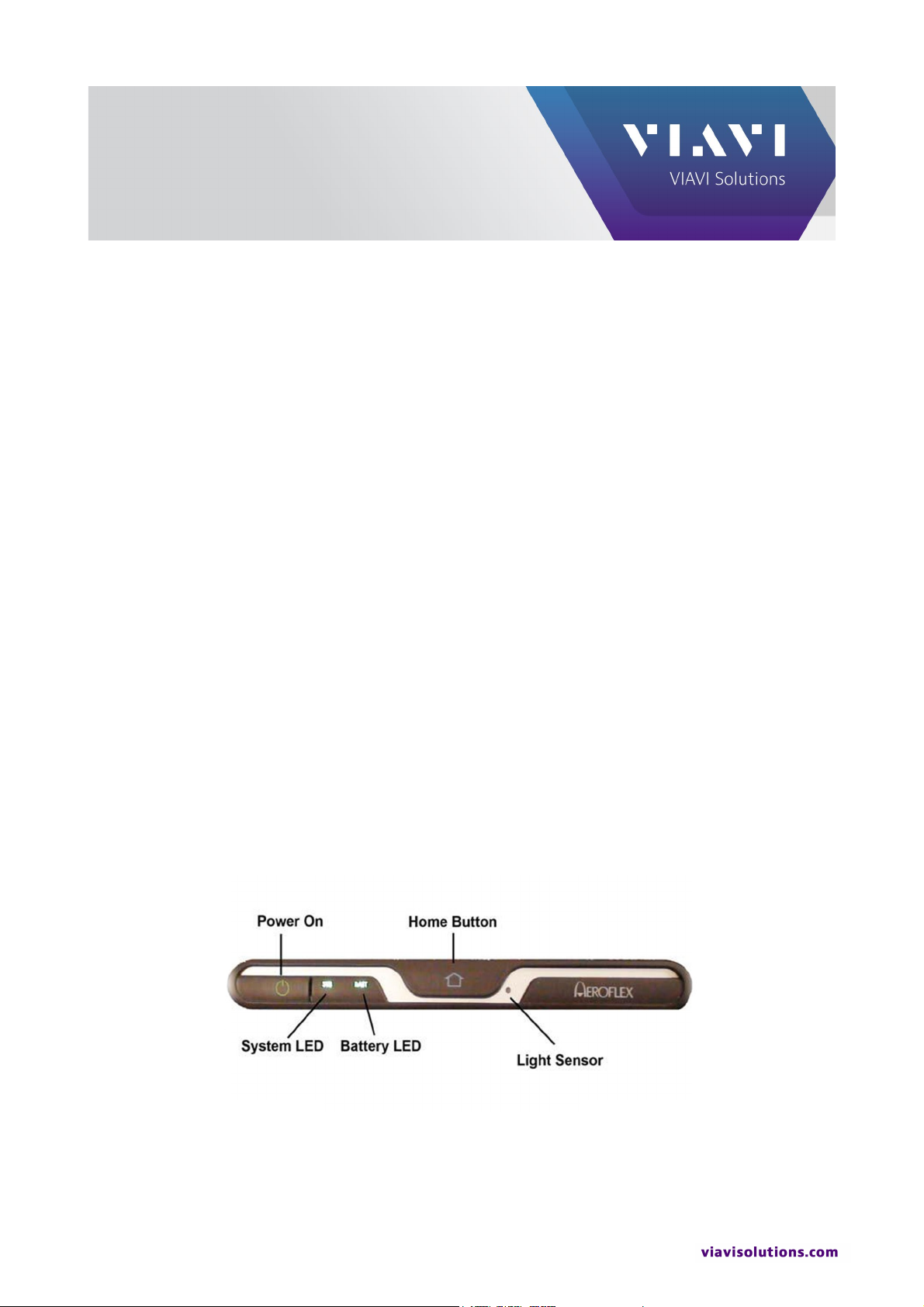
1. Press the Power On button on the front of the ALT-8000 to power on the test set. See Fig. 1-1.
Figure 1-1 Power On Button
Page 2
VIAVI ALT-8000/8015
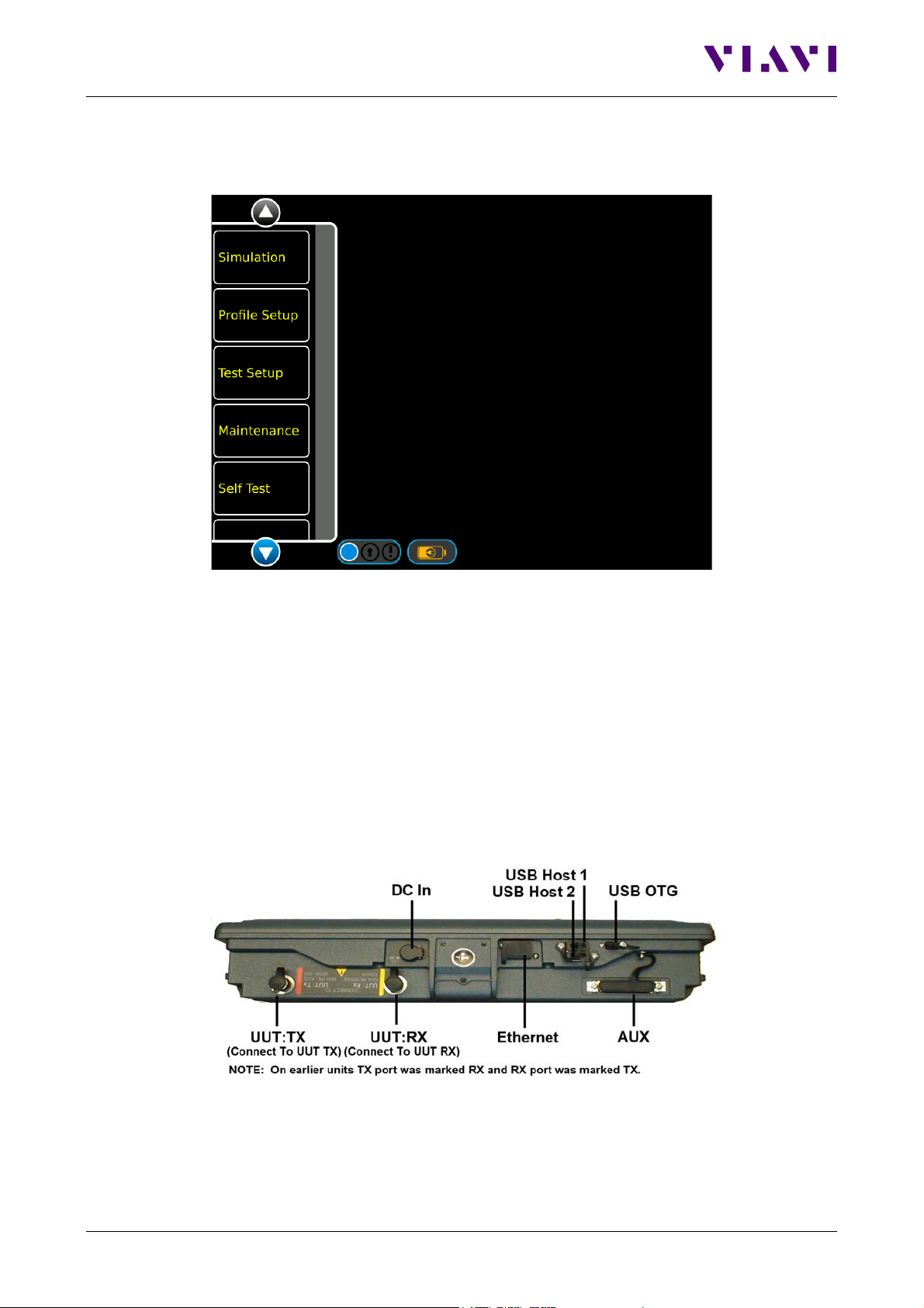
2. On the launch bar, press the Test Setup function key. See Figure 1-2.
Figure 1-2 Launch Bar
3. Locate the two 20 ft cables (P/N 88511 and 89527), the two 4 ft cables (P/N 91253 and 91255) or
the 100 ft cable set (P/N 88500), whichever will be used.
NOTE: The 20 ft cables will be referenced in this procedure.
4. Connect the cable with the yellow ends (P/N 88511) to the UUT:RX (Yellow) connector on the top
panel of the ALT-8000/8015. See Figure 1-3.
5. Connect the cable with the red ends (P/N 89527) to the UUT:TX (Red) connector of the ALT8000/8015. See Figure 1-3.
Page 2
Figure 1-3 ALT-8000/8015 Top Panel
Page 3
VIAVI ALT-8000/8015
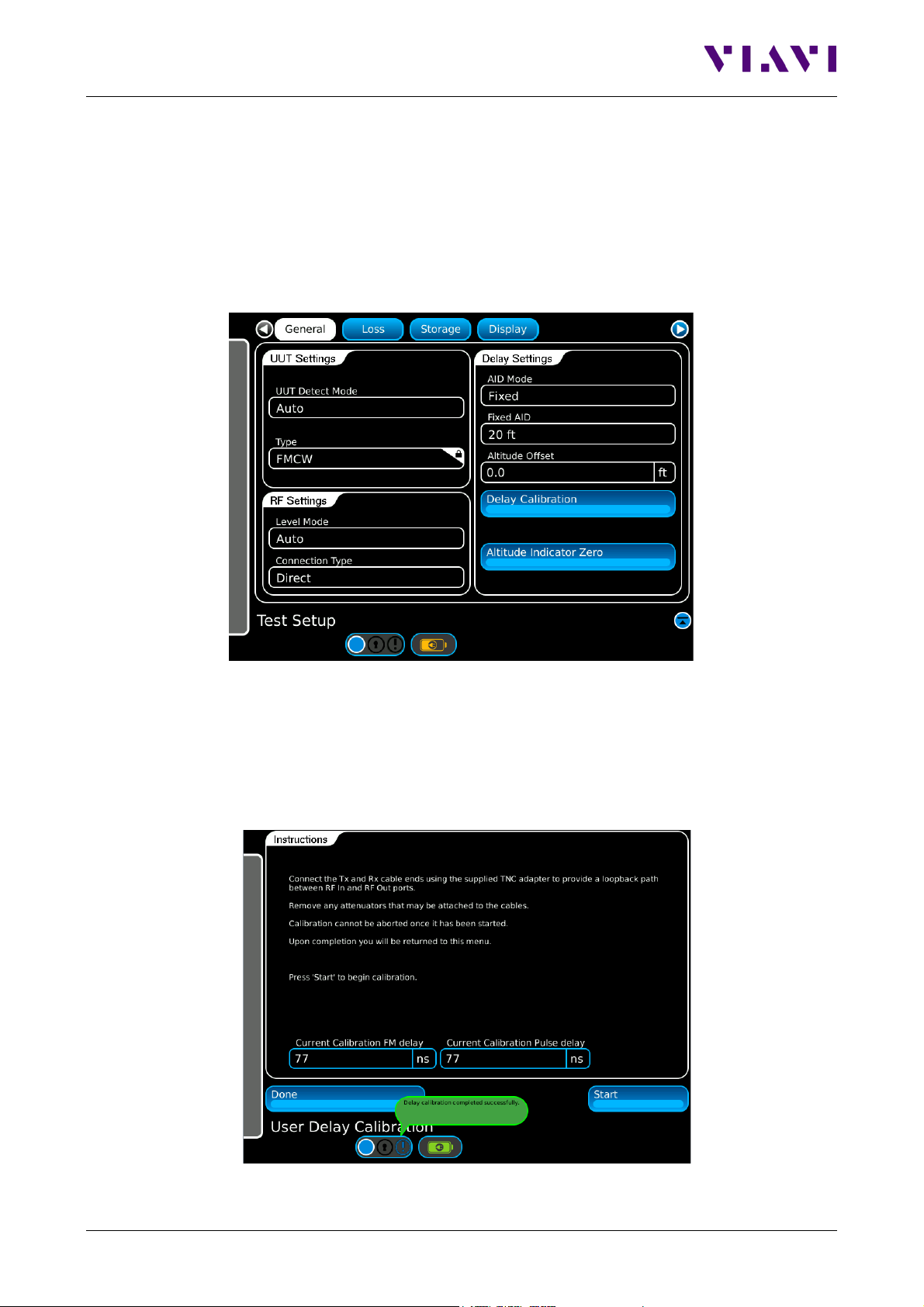
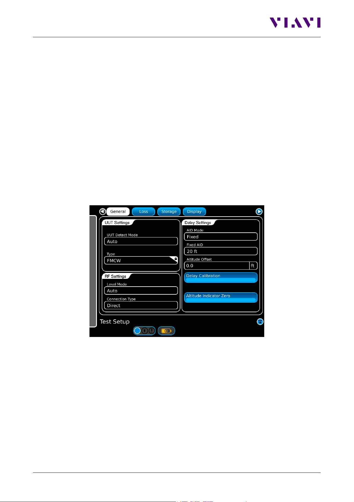
Figure 1-4 Test Setup Screen
Figure 1-5 Delay Calibration Screen
6. Connect the other ends of the 20 ft cables together, using one of the supplied TNC to TNC Adapters
(P/N 38353).
NOTE: For the Delay Calibration, the 20 dB attenuators should NOT be installed on the ALT8000/8015.
7. On the Test Setup screen, press the Delay Calibration button. See Figure 1-4.
8. On the Delay Calibration screen, press the Start button to start the delay calibration. See Figure 1-5.
NOTE: The calibration process is automatic. When delay calibration is complete, the Test Setup screen
is displayed.
Page 3
Page 4
VIAVI ALT-8000/8015
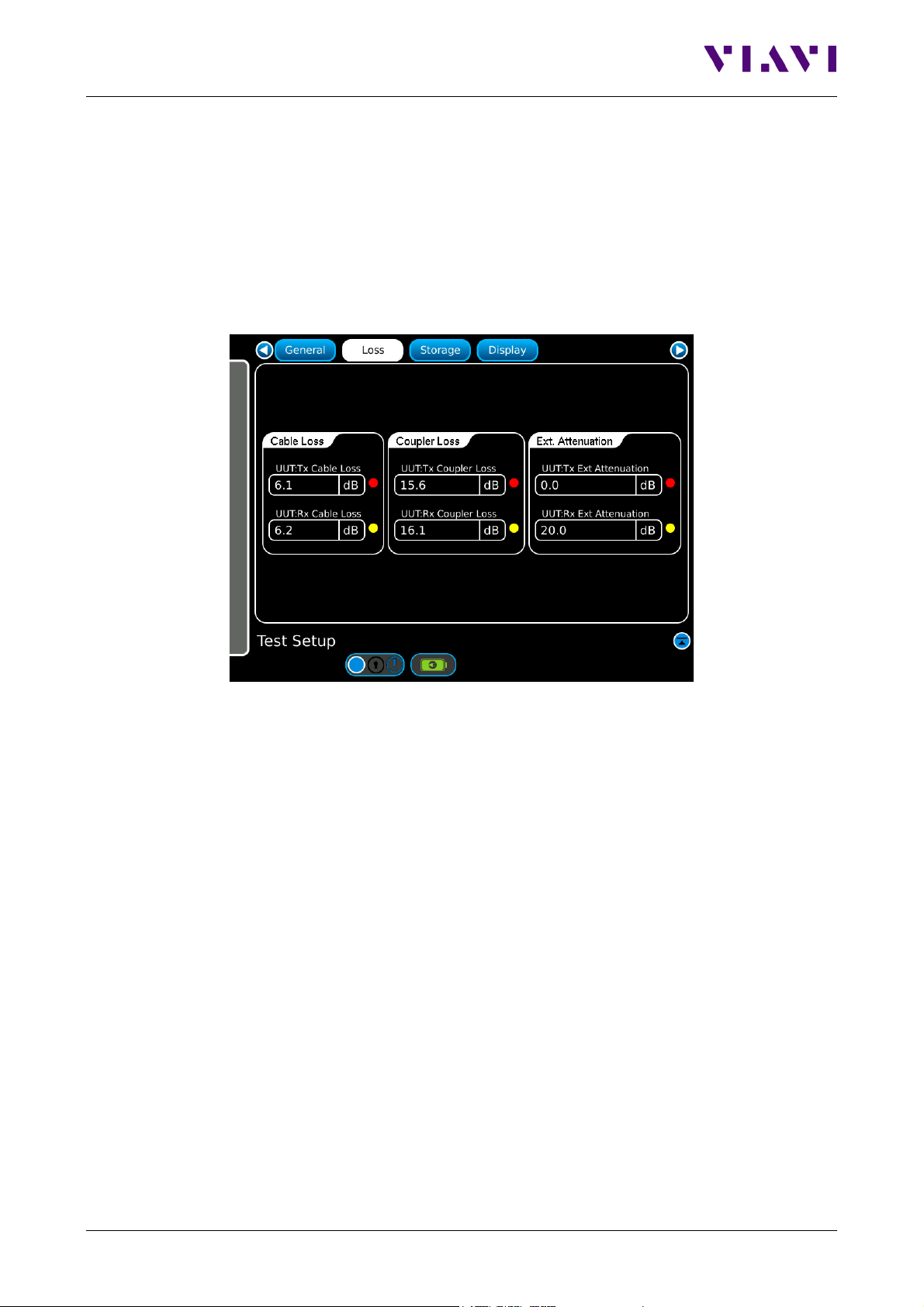
Figure 1-6 Loss Setup Screen
9. Remove the TNC to TNC Adapter from between the TX and RX cables.
10. Set UUT Settings – UUT Detect Mode to Auto. See Figure 1-4.
11. Set RF Settings – Level Mode to Auto. See Figure 1-4.
12. On the Test Setup screen, press the Loss button to go to the Loss setup page. See Figures 1-4
and 1-6.
13. Locate the cable loss value listed on the cable connected to the UUT:TX port (Red) and enter this
value as Cable Loss – UUT:TX Cable Loss (Red). See Figure 1-6.
14. Locate the cable loss value listed on the cable connected to the UUT:RX port (Yellow) and enter this
value as Cable Loss – UUT:RX Cable Loss (Yellow) See Figure 1-6.
15. For coupler testing, enter 20 dB as Ext. Attenuation – UUT:RX Attenuation (Yellow) and for direct
connect testing, enter 40 dB as Ext. Attenuation – UUT:RX Attenuation (Yellow). See Figure 1-6.
NOTE: 20 dB attenuators are only required for pulse type radio altimeters. They are not used for
FMCW and FMCW-CDF type radio altimeters.
16. Locate the coupler with the red UUT:TX label and then locate the Loss Value label on the coupler.
Enter the Coupler Loss Value as Coupler Loss – UUT:TX Coupler Loss (Red). See Figure 1-6.
17. Locate the coupler with the yellow UUT:RX label and then locate the Loss Value label on the
coupler. Enter the Coupler Loss Value as Coupler Loss – UUT:RX Coupler Loss (Yellow). See
Figure 1-6.
Page 4
Page 5
VIAVI ALT-8000/8015
Figure 2-1 Test Setup - Direct
Altitude Simulation Test via Direct-Connect
1. Perform the ALT-8000/8015 Test Setup instructions beginning on page 1.
2. Ensure that two of the 20 dB TNC attenuators are connected to the UUT:RX Port (Yellow) of the
ALT-8000/8015. Connect one 20 dB attenuator directly to the ALT-8000/8015 and then connect the
second 20 dB attenuator directly to the first one. Then connect the coax to these attenuators.
NOTE: 20 dB attenuators are only required for pulse type radio altimeters. They are not used for
FMCW and FMCW-CDF type radio altimeters.
3. Connect the red coaxial cable to the TX port of the radio altimeter being tested. Connect the yellow
coax to the RX port of the radio altimeter being tested.
4. Apply power to the radio altimeter being tested.
5. Set RF Settings – Connection Type to Direct. See Figure 2-1.
6. Touch the gray vertical bar on the left side of the display to display the launch bar.
7. On the launch bar, press the Simulation function key. See Figure 1-2 and 2-2.
Page 5
Page 6

VIAVI ALT-8000/8015
Figure 2-2 Simulation Screen
8. Ensure Control – Simulation is set to Manual. See Figure 2-2.
9. Set Control – Altitude to 100 ft. See Figure 2-2.
10. Press the Run button to start the altitude simulation. See Figure 2-2.
11. Ensure that an RF value is displayed in the UUT Parameters – Power (at UUT) window. If no power
is displayed, check your connections and power to the UUT. See Figure 2-3.
12. Verify that the UUT Parameters are all within the desired range.
13. Verify that the display on the RADIO ALTIMETER displays approximately 100 ft.
NOTE: The Delay Settings – Altitude Offset setting may be adjusted to make the display read
exactly 100 ft. See Figure 2-1.
14. Press the Control - Altitude Pause button to change the simulated altitude. See Figure 2-3.
15. Set Control - Current Altitude to desired test altitude (i.e. 500 ft, 1000 ft, 1500 ft.) up to maximum
altitude capable for your radio.
16. Verify that the UUT Parameters are all within the desired range.
NOTE: Link margin is only displayed for pulse type radio altimeters.
17. Verify that the display on the RADIO ALTIMETER displays approximately the same as the Control
Current Altitude setting.
18. Press the Stop button to stop the altitude simulation. See Figure 2-3.
Page 6
Page 7

VIAVI ALT-8000/8015
Figure 2-3 Simulation Screen
Altitude Simulation Test via Coupler
1. Perform the ALT-8000/8015 Test Setup instructions beginning on page 1.
2. Ensure that one of the 20 dB TNC attenuators is connected to the UUT:RX Port (Yellow) of the ALT8000/8015. Connect the 20 dB attenuator directly to the ALT-8000/8015 and then connect the coax
to the attenuator.
NOTE: 20 dB attenuators are only required for pulse type radio altimeters. They are not used for
FMCW and FMCW-CDF type radio altimeters.
3. Locate the UUT:RX (Yellow) coupler and connect it to the UUT:RX (Yellow) cable.
4. Adjust the support poles to a length that will allow the compression poles to press the couplers into
the aircraft just tight enough to hold the couplers in place.
5. Place the UUT:TX (Red) coupler over the TX antenna, with the arrow pointing toward the front of the
aircraft.
NOTE: Some aircraft may have the antennas oriented toward each other and not toward the front of
the aircraft. To determine the orientation, rotate the coupler 90 degrees at a time while watching the
output power reading on the ALT-8000/8015. The highest power measurement indicates the correct
placement of the coupler and the orientation of the antenna. Leave the coupler in the position that
produced the highest power measurement.
Page 7
Page 8

VIAVI ALT-8000/8015
6. Place the UUT:RX (Yellow) coupler over the RX antenna, with the arrow pointing toward the front of
the aircraft.
NOTE: If the TX antenna coupler is oriented toward the front of the aircraft, then orient the RX
coupler toward the front of the aircraft. If the TX antenna coupler is pointed toward the RX antenna,
then orient the RX coupler toward the TX antenna coupler.
7. Touch the gray vertical bar on the left side of the display to display the launch bar.
8. On the launch bar, press the Simulation function key. See Figures 1-2 and 2-2.
9. Ensure Control – Simulation is set to Manual. See Figure 2-2.
10. Set Control – Altitude to 100 ft. See Figure 2-2.
11. Press the Run button to start the altitude simulation. See Figure 2-2.
12. Ensure that an RF value is displayed in the UUT Parameters – Power (at UUT) window. If no power
is displayed, check your connections, coupler positioning, and power to the UUT. See Figure 2-3.
13. Verify that the UUT Parameters are all within the desired range.
14. Verify that the display on the RADIO ALTIMETER displays approximately 100 ft.
NOTE: The Delay Settings – Altitude Offset setting may be adjusted to make the display read
exactly 100 ft. See Figure 2-1.
15. Press the Control - Altitude Pause button to change the simulated altitude. See Figure 2-3.
16. Set Control - Current Altitude to desired test altitude (i.e. 500 ft, 1000 ft, 1500 ft.) up to maximum
altitude capable for your radio.
17. Verify that the UUT Parameters are all within the desired range.
18. Verify that the display on the RADIO ALTIMETER displays approximately the same as the Control–
Current Altitude setting.
19. Press the Stop button to stop the altitude simulation. See Figure 2-3.
Page 8
Page 9

VIAVI ALT-8000/8015
Figure 4-1 Profile Setup Screen
Profile Test – Direct or Coupler
1. Perform the ALT-8000/8015 Test Setup instructions beginning on page 1.
2. Perform one of the two following steps depending upon whether you are direct-connecting or using a
coupler.
- Direct-Connect: Locate two of the 20 dB TNC attenuators and connect both to the UUT:RX Port
(Yellow) of the ALT-8000/8015. Connect one 20 dB attenuator directly to the ALT-8000/8015
and then connect the second 20 dB attenuator directly to the first one. Then connect the coax to
these attenuators. Ensure that 40 dB is entered as the Test Setup – Loss – Ext. Attenuation –
UUT:RX Ext Attenuation value.
- Coupler: Locate one of the 20 dB TNC attenuators and connect it to the UUT:RX Port (Yellow)
of the ALT-8000/8015. Connect the 20 dB attenuator directly to the ALT-8000/8015 and then
connect the coax to the attenuator. Ensure that 20 dB is entered as the Test Setup – Loss –
Ext. Attenuation – UUT:RX Ext Attenuation value.
3. Set RF Port Settings – Connection Type to Direct or Coupler. See Figure 2-1.
4. Touch the gray vertical bar on the left side of the display to display the launch bar.
5. On the launch bar, press the Profile Setup function key. See Figures 1-2 and 4-1.
6. To add a leg to the profile, press the Add button and the Add Leg pop-up window will be displayed.
See Figures 4-1 and 4-2.
Page 9
Page 10

VIAVI ALT-8000/8015
Figure 4-2 Profile Setup
7. Enter a Start Altitude of 100 ft.
8. Enter a Stop Altitude of 100 ft.
9. Enter a Leg Duration of 30 s.
10. Press the Enter button to add Leg 1 to the profile. See Figures 4-2 and 4-3.
11. Press the Add button and the Add Leg pop-up window will be displayed again. See Figures 4-1, 4-2
and 4-3.
12. Enter a Start Altitude of 100 ft.
13. Enter a Stop Altitude of 500 ft.
14. Enter an Altitude Rate of 1000 ft/min.
15. Press the Enter button to add leg to the profile. See Figures 4-2 and 4-3.
Page 10
Page 11

VIAVI ALT-8000/8015
Figure 4-3 Complete Setup
16. Press the Add button and the Add Leg pop-up window will be displayed. See Figures 4-1 and 4-2.
17. Enter a Start Altitude of 500 ft.
18. Enter a Stop Altitude of 500 ft.
19. Enter a Leg Duration of 30 s.
20. Press the Enter button to add leg to the profile. See Figures 4-2 and 4-3.
21. Press the Add button and the Add Leg pop-up window will be displayed again. See Figures 4-1, 4-2
and 4-3.
22. Enter a Start Altitude of 500 ft.
23. Enter a Stop Altitude of 1000 ft.
24. Enter an Altitude Rate of 1000 ft/min.
25. Press the Enter button to add leg to the profile. See Figures 4-2 and 4-3.
26. Press the Add button and the Add Leg pop-up window will be displayed. See Figures 4-1 and 4-2.
27. Enter a Start Altitude of 1000 ft.
28. Enter a Stop Altitude of 1000 ft.
29. Enter a Leg Duration of 30 s.
Page 11
Page 12

VIAVI ALT-8000/8015
Figure 4-4 Simulation – Profile Screen
30. Press the Enter button to add leg to the profile. See Figures 4-2 and 4-3.
31. Press the Add button and the Add Leg pop-up window will be displayed again. See Figures 4-1, 4-2
and 4-3.
32. Enter a Start Altitude of 1000 ft.
33. Enter a Stop Altitude of 1500 ft.
34. Enter an Altitude Rate of 1000 ft/min.
35. Press the Enter button to add leg to the profile. See Figures 4-2 and 4-3.
36. Touch the gray vertical bar on the left side of the display to display the launch bar.
37. On the launch bar, press the Simulation function key. See Figures 1-2 and 2-2.
38. Set Control – Simulation to Profile. See Figure 4-4.
39. Press the Run button to start the profile simulation. See Figure 4-4.
40. Verify that the UUT Parameters are all within the desired range. You will have 30 seconds to verify
the parameters.
41. Verify that the displayed altitude on the RADIO ALTIMETER display tracks the altitude displayed in
the Control – Current Altitude window. See Figure 4-4.
42. Press the Stop button to stop the profile simulation.
Page 12
Page 13

VIAVI ALT-8000/8015
Figure 5-1 Test Setup – RF Settings - Manual
Radio Altimeter Sensitivity Test – Direct or Coupler
1. Perform the ALT-8000/8015 Test Setup instructions beginning on page 1.
2. Perform one of the two following steps depending upon whether you are Direct Connecting or using
a Coupler.
- DIRECT CONNECT: Locate two of the 20 dB TNC attenuators and connect both to the UUT:RX
Port (Yellow) of the ALT-8000/8015. Connect one 20 dB attenuator directly to the ALT8000/8015 and then connect the second 20 dB attenuator directly to the first one. Then connect
the coax to these attenuators. Ensure that 40 dB is entered as the Test Setup – Loss – Ext.
Attenuation – UUT:RX Ext Attenuation value.
- COUPLER: Locate one of the 20 dB TNC attenuators and connect it to the UUT:RX Port
(Yellow) of the ALT-8000/8015. Connect the 20 dB attenuator. Ensure that 20 dB is entered as
the Test Setup – Loss – Ext. Attenuation – UUT:RX Ext Attenuation value.
3. Perform the 100 ft altitude setup steps from Step 2 (Direct Connect) or Step 3 (Coupler) above.
4. Touch the gray vertical bar on the left side of the display to display the launch bar.
5. On the launch bar, press the Test Setup function key. See Figure 1-2.
6. Set RF Settings – Level Mode to Manual. See Figure 5-1.
7. Touch the gray vertical bar on the left side of the display to display the launch bar.
8. On the launch bar, press the Simulation function key. See Figure 1-2.
Page 13
Page 14

VIAVI ALT-8000/8015
Figure 5-2 Simulation – RX Sensitivity
9. Touch the Control – RF Level window to bring up the RF Level adjustment window.
NOTE: You may enter the values manually; use the adjustment dial; or use the slide bar to change
the RF Level. See Figure 5-2.
10. Adjust the RF level downward until the RADIO ALTIMETER display stops reporting the 100 ft
altitude.
11. The RF level where the RADIO ALTIMETER stops reporting the correct altitude is the sensitivity
level of the receiver.
12. Press the Stop button to stop the profile simulation.
Contact Us:
+1 316 522 4981
avcomm.sales@viavisolutions.com
To reach the VIAVI office nearest you, visit viavisolutions.com/contact.
© 2019 VIAVI Solutions Inc.
Product specifications and descriptions in this document are subject to change without notice.
February 22, 2019
Page 14
 Loading...