

Page 1

8380 RPC
Return Path Combiner
User’s Guide
Page 2

Notice
Every effort was made to ensure that the information in this manual was accurate at the time
of printing. However, information is subject to change without notice, and VIAVI reserves the
right to provide an addendum to this manual with information not available at the time that this
manual was created.
Copyright/Trademarks
© Copyright 2018 VIAVI Solutions Inc. All rights reserved. No part of this guide may be
reproduced or transmitted, electronically or otherwise, without written permission of the
publisher. VIAVI Solutions and the VIAVI logo are trademarks of VIAVI Solutions Inc. (“Viavi”).
All other trademarks and registered trademarks are the property of their respective owners.
Copyright release
Reproduction and distribution of this guide is authorized for US Government purposes only.
Ordering information
This guide is a product of VIAVI Technical Publications Department, issued as part of the
product. The catalog number for a published guide is Catalog Number - printed. The catalog
number for an electronic guide on USB is Catalog Number - electronic.
Terms and conditions
Specications, terms, and conditions are subject to change without notice. The provision
of hardware, services, and/or software are subject to VIAVI standard terms and conditions,
available at www.viavisolutions.com/en/terms-and-conditions.
8380 RPC User’s Guide
Document Num., Rev. 3 May 2018Page 2
Page 3

Table of Contents
Chapter 1
General Information ..................................................................................................................5
Ordering Information ..............................................................................................................5
Where to Get Technical Support ............................................................................................5
How this Manual is Organized ...............................................................................................6
Conventions Used in this Manual...........................................................................................7
Precautions ............................................................................................................................7
Chapter 2
Introduction & Installation ........................................................................................................9
What is the 8380 RPC?..........................................................................................................9
System Diagram...................................................................................................................10
8380 RPC Features .............................................................................................................11
Equipment Supplied with Your 8380 RPC ............................................................................11
A Guided Tour of Your 8380 RPC ........................................................................................12
Front View .......................................................................................................................12
Rear View .......................................................................................................................13
Installing the 8380 RPC .......................................................................................................14
Installing the 8380 RPC .......................................................................................................15
Unit Installation ...............................................................................................................15
RS-485 Connections.......................................................................................................16
RS-485 Addressing .........................................................................................................17
Return Path Connections Between Master & Slave .......................................................19
Chapter 3
Setup .........................................................................................................................................21
Computer System Requirements .........................................................................................21
Software Installation .............................................................................................................21
8380 RPC Setup Software Overview ...................................................................................28
Installing the USB Drivers ....................................................................................................29
Connecting & Disconnecting the 8380 RPC ........................................................................30
Network Settings (Master Units Only) ..................................................................................31
System Settings ...................................................................................................................32
Upgrading Master Unit Firmware ....................................................................................33
Upgrading Slave Unit Firmware ......................................................................................34
8380 RPC User’s Guide
Document Num., Rev. 3May 2018 Page 3
Page 4

User Settings........................................................................................................................35
Adding a New User ...................................................................................................36
Removing a User.......................................................................................................36
User Name ................................................................................................................36
Password...................................................................................................................36
Privilege.....................................................................................................................36
Chapter 4
Web Access..............................................................................................................................37
Accessing the 8380 RPC with a Web Browser ....................................................................37
8380 RPC Homepage ..........................................................................................................38
Administrator Options...........................................................................................................39
Device Settings ...............................................................................................................40
Device and Port Names ............................................................................................41
Adding and Removing Devices .................................................................................41
Adding and Removing Ports......................................................................................42
System Settings ..............................................................................................................43
System Date/Time .....................................................................................................44
Port Timeout (Hours) .................................................................................................44
User Settings .............................................................................................................45
Adding a New User ...................................................................................................46
Removing a User.......................................................................................................46
User Name ................................................................................................................46
Password...................................................................................................................46
Privilege.....................................................................................................................46
Select Ports ..........................................................................................................................47
Active Port Count ............................................................................................................48
Devices & Ports Table .....................................................................................................48
Master Ports ..............................................................................................................48
Slave Devices............................................................................................................48
Slave Ports ................................................................................................................49
Chapter 5
Appendix ..................................................................................................................................51
Specications .......................................................................................................................51
Limited Warranty ..................................................................................................................53
8380 RPC User’s Guide
Document Num., Rev. 3 May 2018Page 4
Page 5

Chapter 1
General Information
Ordering Information
For additional information about our products and services, contact your local Viavi
representative or visit https://www.viavisolutions.com/en-us/how-buy.
Where to Get Technical Support
Phone US: +1-844-GO-VIAVI or +1-844-468-4284
Outside US: +1-855-275-5378
Email: Trilithic.support@viavisolutions.com
Website: https://support.viavisolutions.com/welcome
8380 RPC User’s Guide
Document Num., Rev. 3May 2018 Page 5
Page 6

How this Manual is Organized
This manual is divided into the following chapters:
• Chapter 1, “General Information” provides contact information and describes how this
operation manual is structured.
• Chapter 2, “Introduction and Installation” introduces what the 8380 RPC is and what it
does. This chapter discusses the practical application, connections, and controls of the
8380 RPC.
• Chapter 3, “Setup” describes the steps needed to perform initial conguration of the
8380 RPC.
• Chapter 4, “Web Access” shows how to access the 8380 RPC through a web browser.
• Chapter 5, “Appendix” shows the technical specications of the 8380 RPC.
8380 RPC User’s Guide
Document Num., Rev. 3 May 2018Page 6
Page 7
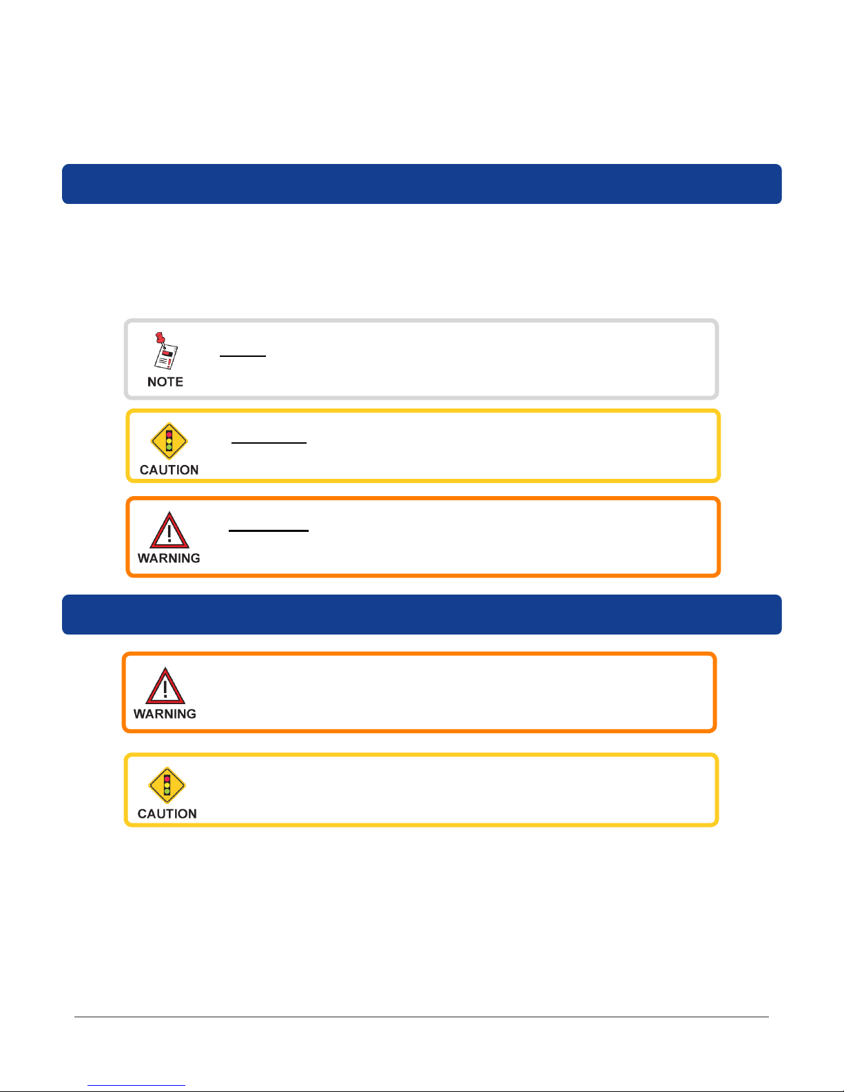
Conventions Used in this Manual
This manual has several standardized conventions for presenting information:
• Connections, menus, menu options, and user-entered text and commands appear in
bold.
• Section names, web, and e-mail addresses appear in italics.
A NOTE is information that will be of assistance to you related
to the current step or procedure.
A CAUTION alerts you to any condition that could cause a
mechanical failure or potential loss of data.
A WARNING alerts you to any condition that could cause
personal injury.
Precautions
Do not use the 8380 RPC in any manner not recommended by
the manufacturer
The 8380 RPC may not operate correctly in the presence of a
strong electromagnetic eld.
8380 RPC User’s Guide
Document Num., Rev. 3May 2018 Page 7
Page 8

8380 RPC User’s Guide
Document Num., Rev. 3 May 2018Page 8
Page 9

Chapter 2
Introduction & Installation
What is the 8380 RPC?
The 8380 RPC™ Return Path Combiner is a 16 x 1 non-blocking RF matrix switch designed
for use with the VIAVI 8310 RSA™ in the return path of CATV systems. The 8380 RPC has 16
input ports that can be combined into a single output.
There are two versions of the 8380 RPC available, a master and a slave. The master 8380
RPC is used to control each slave using an RS-485 connection. The output from each slave
8380 RPC connects to a corresponding input on the master unit. Slave 8380 RPCs have the
ability to be upgraded to a master unit.
A complete 8380 RPC system consists of a master and 16 slaves allowing for 256 inputs to be
combined into a single output. The output of the master may be used for a variety of tests.
Whether you are a technician in the headend or the eld, the master 8380 RPC can be
controlled from any location with an Internet connection. The 8380 RPC includes a built-in web
based conguration that is compatible with any web browser including those on mobile devices
and the DSP family of devices.
This versatility allows the technician to connect many ports, but only sweep on the ports they
are currently testing, while the other ports remain on stand-by.
8380 RPC User’s Guide
Document Num., Rev. 3May 2018 Page 9
Page 10
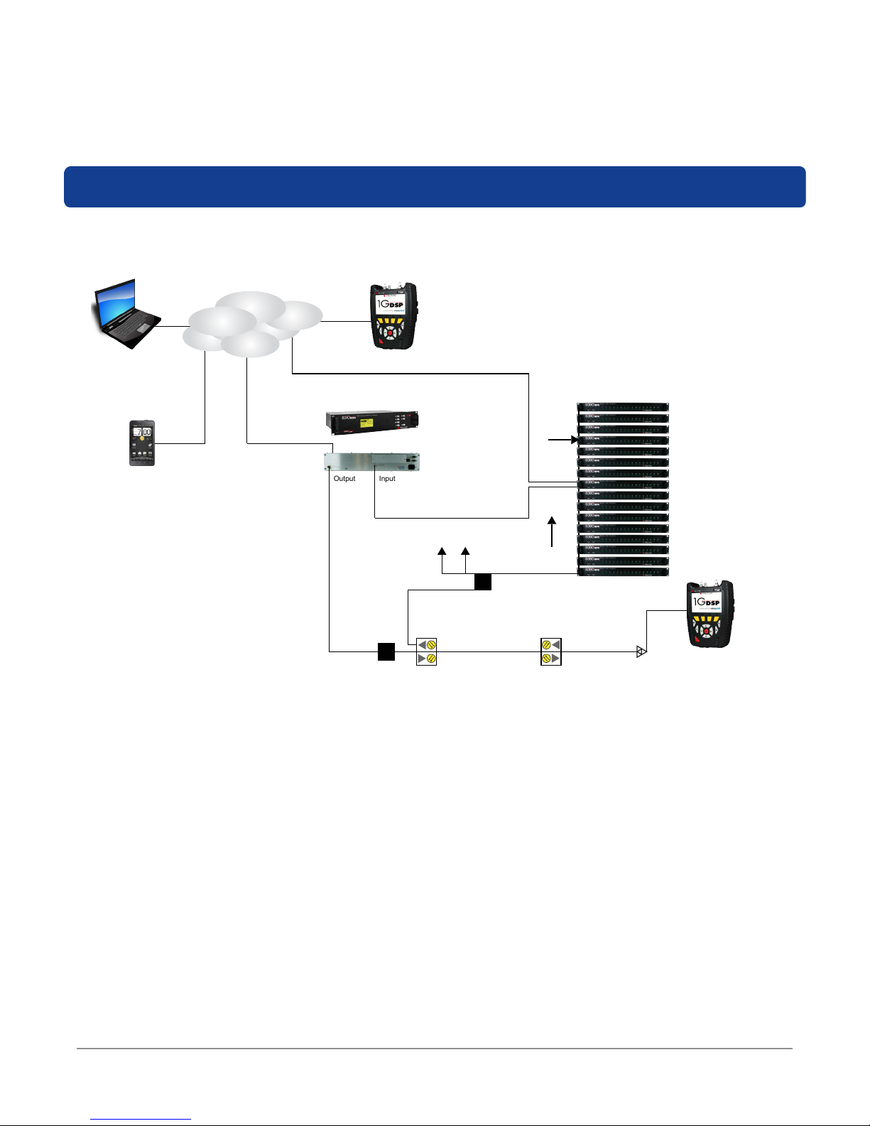
System Diagram
The following diagram shows the typical deployment of an 8380 RPC system.
Internet
Laptop/Desktop
Computer
Cell Phone, PDA,
or iPad
Ethernet
Forward
Telemetry
1G DSP
8310 RSA
Output
Input
Splitter
Combined
Output
VoIP
CMTS
Ethernet
Splitter
Light (fiber)
RS-485
Cable
Continue
Split
RF
RPC Switch
Test Point
Master
1G DSP
8380 RPC User’s Guide
Document Num., Rev. 3 May 2018Page 10
Page 11

8380 RPC Features
The 8380 RPC includes the following features:
• 16 x 1 Non-Blocking RF Matrix Switch
• 16 Ports per Switch
• 17 8380 RPC Units (1 Master, 16 Slaves) Conguration for 256 Ports Max
• ViewPoint Master Control of All RPC Switches
Equipment Supplied with Your 8380 RPC
The 8380 RPC comes with the following:
• 8380 RPC Return Path Combiner
• AC to DC Power Adapter
• USB Cable (Type B to Type A) for Initial Conguration and for downloading rmware
upgrades, included with Master unit only
• RS-485 Cable with RJ-11 connectors
• Conguration Software and Operation manual on CD
8380 RPC User’s Guide
Document Num., Rev. 3May 2018 Page 11
Page 12
A Guided Tour of Your 8380 RPC
Front View
3
MASTER UNIT
112
SLAVE UNIT
2
1. Power – This LED will illuminate when power is supplied to the unit.
2. Status – This LED will illuminate when the unit is ready for operation. This LED will
blink if there is an RS-485 connection error.
3. Label –This label when present indicates the device is a Master unit.
4. Input Active – These LEDs will illuminate when the individual return path inputs are
activated.
4
4
8380 RPC User’s Guide
Document Num., Rev. 3 May 2018Page 12
Page 13
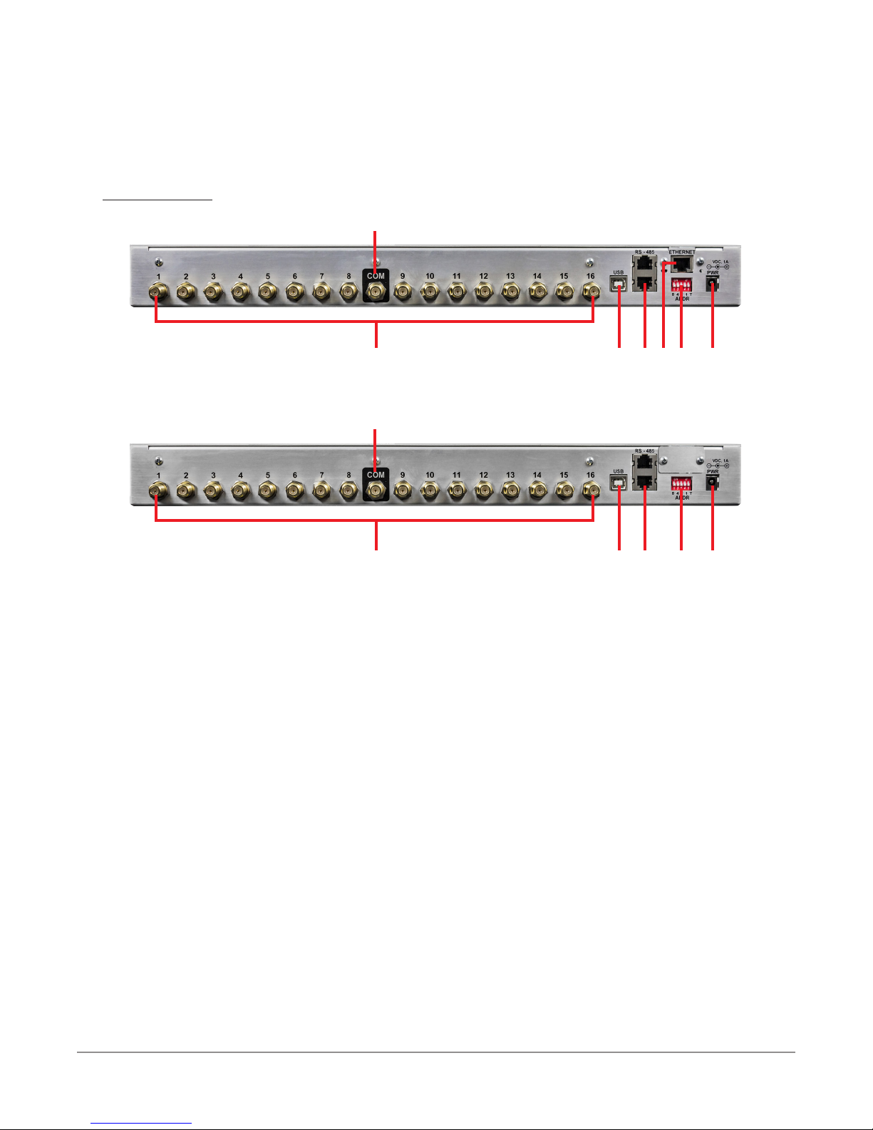
Rear View
MASTER UNIT
1
15
2
33445 667
1
SLAVE UNIT
15
2
7
1. Combined Output – This is the combined output of the 16 return path inputs.
2. Return Path Input (1 through 16) – These are inputs 1 through 16 of individual
return path ports that the 8380 RPC combines into a single output.
3. USB Port – This is a USB Type B connector that is used for initial conguration of
Master units and to perform rmware upgrades. Upon removing the USB cable from
the 8380 RPC, the power to the device should be cycled.
4. RS-485 Control Ports – These are RJ-11 Master/Slave control ports for use when
connecting master units to slave units.
5. Ethernet Port – This port is only available on Master units and is used to directly
control the 8380 RPC system via a network connection. Initial conguration using the
RPC Setup Software must be completed prior to connecting to the Master unit via
a network connection. The ethernet connection to the Master unit should be made
prior to powering the unit.
6. RS-485 Address DIP Switch – This DIP switch is used to set the RS-485 control
address of the 8380 RPC. This is also used to enable the RS-485 termination on the
rst and last 8380 RPC in the RS-485 communications chain. It is recommended
that all RS-485 connections be made prior to powering the corresponding units.
7. Power Input – Connect the included AC to DC Power Adapter to this port.
8380 RPC User’s Guide
Document Num., Rev. 3May 2018 Page 13
Page 14
Installing the 8380 RPC
The following section explains the procedure used to physically install the 8380 RPC. In order
to properly setup the 8380 RPC the following steps must be completed in this order. Do not
skip any steps.
DO NOT plug in the power cord of the 8380 RPC until
instructed below.
1. Mount the 8380 RPC in a standard rack using four retaining screws.
2. Connect an ethernet cable to the master unit.
3. Connect the RS-485 cables and set the addresses and terminations of the master and
slave units accordingly.
4. Plug the AC to DC Power Adapter of the 8380 RPC into the Power Input and then into
an AC power source. When power is supplied to the 8380 RPC, the Power LED on the
front panel of the unit will illuminate.
If the Power LED is not illuminated upon connecting power to
the 8380 RPC, contact 1-844-GO-VIAVI for assistance.
5. When the unit is ready for operation, the Status LED on the front panel of the unit will
illuminate.
Upon reboot (regardless of source/cause), the master 8380
RPC will load the last saved device settings, system settings,
user settings, and network conguration as well as deactivate
all ports present in the 8380 RPC system.
8380 RPC User’s Guide
Document Num., Rev. 3 May 2018Page 14
Page 15
Installing the 8380 RPC
The following section explains the procedure used to physically connect multiple 8380 RPC
units using the RS-485 Control Port. In order to properly setup the 8380 RPC the following
steps must be completed in this order. Do not skip any steps.
Unit Installation
When installing a Master unit
with several Slave units, the
Master unit should always be
placed in the middle of the
“stack”. Then, Slave units 01
through 08 should be placed
above the Master unit and
Slave Units 09 through 16
should be placed below the
Master unit.
This method of installation is
used to reduce the required
cable length between Master
and Slave units while keeping
the connections from having to
cross each other.
All units should use the same
length cable. The cable length
is determined by the longest
length needed as measured
from the COM port of the Slave
unit furthest from the Master
unit to the corresponding input
of the Master unit. Once the
cable length is determined,
ALL cables connecting the
Master unit to the Slave units
should be the same length.
8380 RPC User’s Guide
Document Num., Rev. 3May 2018 Page 15
Page 16
RS-485 Connections
Connect the RS-485 Control Port from the Master unit to the RS-485 Control Port of the
Slave unit. Continue connecting the RS-485 Control Port of each Slave unit to the RS-
485 Control Port of the next Slave unit until all Slave units have been connected. See the
following diagram for an example of the typical RG-59 & RS-485 connections.
15
15
15
15
15
8380 RPC User’s Guide
Document Num., Rev. 3 May 2018Page 16
Page 17

RS-485 Addressing
The RS-485 Address DIP Switch is used to set the RS-485 address of each 8380 RPG.
The address is determined by adding the two values shown below each switch that is set to
ON. See the following table for an example of each switch setting.
The RS-485 address of the Master is automatically set to 16, and the termination for the
last slave at each end of the RS-485 chain must be set to ON.
See next page for a Table of Dip Switch Addresses and Settings.
The device number is equal to the RS-485 address plus one.
8380 RPC User’s Guide
Document Num., Rev. 3May 2018 Page 17
Page 18

DEVICE ADDRESS DIP SWITCH DEVICE ADDRESS DIP SWITCH
Not Used
Master
Leave Set
Slave 09 8
to Zero (0)
Slave 01 0 Slave 10 9
Slave 02 1 Slave 11 10
Slave 03 2 Slave 12 11
Slave 04 3 Slave 13 12
Slave 05 4 Slave 14 13
Slave 06 5 Slave 15 14
Slave 07 6 Slave 16 15
Last Slave
Slave 08 7
Unit at Each
End of RS-485
T
Control Chain
8380 RPC User’s Guide
Document Num., Rev. 3 May 2018Page 18
Page 19

Return Path Connections Between Master & Slave
PATH INPUT
PATH INPUT
This section explains the procedure used to physically connect multiple 8380 RPC units
using the return path inputs. The Combined Output (COM) port of each slave must be
connected to the correct Return Path Input of the master unit. The table below shows
which slave unit must be connected to each of the return path inputs of the master unit.
MASTER RETURN
1 1 9 9
2 2 10 10
3 3 11 11
4 4 12 12
5 5 13 13
6 6 14 14
7 7 15 15
8 8 16 16
SLAVE NUMBER
MASTER RETURN
SLAVE NUMBER
8380 RPC User’s Guide
Document Num., Rev. 3May 2018 Page 19
Page 20

8380 RPC User’s Guide
Document Num., Rev. 3 May 2018Page 20
Page 21

Chapter 3
Setup
Computer System Requirements
In order to install the 8380 RPC Setup software, the following computer hardware and software
conditions must be met:
• Windows XP or newer operating system
• A screen resolution of at least 800 x 600 pixels
• 500 MHz processor with 512 MB of RAM and 100 MB of free hard drive space
In addition, a USB Cable (Type B to Type A) is required in order to establish communications
between the 8380 RPC Setup software and the 8380 RPC.
Software Installation
Perform the following steps to install the 8380 RPC Setup software from the included CD:
1. Depending on which operating system you are using, logging in as the system
administrator may be necessary.
2. Insert the 8380 RPC Setup software CD into the appropriate drive.
3. If Autorun is enabled for the CD-ROM drive, the 8380 RPC Setup software setup
program will start automatically. If the setup program does not start, select the Windows
Start button, then select Run and type [drive]:\setup.exe, then select OK (substitute
the appropriate drive letter in the command line, in place of [drive]).
4. Depending on which operating system you are using, the “Open File - Security Warning”
dialog box may appear. If this dialog box appears, select Run.
8380 RPC User’s Guide
Document Num., Rev. 3May 2018 Page 21
Page 22

5. The “Welcome to the Trilithic Return
Path Combiner Setup Wizard” window
will appear. Select Next.
6. The “Select Installation Folder” window
will appear. Select Next to install the
software in the default location.
8380 RPC User’s Guide
Document Num., Rev. 3 May 2018Page 22
Page 23

7. The “Conrm Installation” window will
appear. Select Next to conrm the
installation.
8. The “Installing Trilithic Return Path
Combiner Setup” window will appear.
Select Next to conrm the installation.
9. The USB driver installer will
automatically start. Select Install to
begin the installation.
8380 RPC User’s Guide
Document Num., Rev. 3May 2018 Page 23
Page 24

10. The “Installation Completed Successfully”
window will appear. Select OK to
acknowledge the message.
11. The “Installation Complete” window
will appear. Select Close to exit the
installation.
8380 RPC User’s Guide
Document Num., Rev. 3 May 2018Page 24
Page 25

12. From the PC’s Control Panel, select the Device Manager icon. Find the entry for
“Trilithic 8380RPC SN ######” and right click on the device as shown in the following
image and select Update Driver Software. Note that the icon for the device is located
under “Other Devices” section and has an exclamation point (!) indicating the driver is
not yet installed completely.
8380 RPC User’s Guide
Document Num., Rev. 3May 2018 Page 25
Page 26

13. The “Update Driver Software” window
will appear. Select the Browse My
Computer for Driver Software option.
14. Select Browse to select the path shown
in the image to the right and then select
Next.
15. Select the Install this Driver Software
Anyway option to install the driver.
8380 RPC User’s Guide
Document Num., Rev. 3 May 2018Page 26
Page 27

16. When the driver is nished installing, the
“Windows has Successfully Updated Your
Driver Software” notication window will
appear. Select Close.
17. Note that the icon for the device has moved to the “Ports” section and no longer has an
exclamation point (!). This indicates the driver is installed completely and ready to use.
8380 RPC User’s Guide
Document Num., Rev. 3May 2018 Page 27
Page 28

8380 RPC Setup Software Overview
To start the 8380 RPC Setup software, select the “Return Path Combiner Setup” link from the
PC desktop or Start menu. The 8380 RPC Setup software will appear as shown below:
Conguration Tabs
Connection Settings
General
Event Table
8380 RPC User’s Guide
Document Num., Rev. 3 May 2018Page 28
Page 29

Installing the USB Drivers
The USB drivers were installed in the Return Path Combiner Setup Wizard, but if you need to
update or reinstall the drivers, perform the following steps:
1. From the 8380 RPC Setup software, select
the Install USB Driver button in the lower left
corner of the software.
2. Follow the steps on the previous pages to
update the drivers.
8380 RPC User’s Guide
Document Num., Rev. 3May 2018 Page 29
Page 30

Connecting & Disconnecting the 8380 RPC
Before any changes can be made to the setup of the 8380 RPC, the 8380 RPC Setup software
must connect via USB with the 8380 RPC. Perform the following steps to connect the 8380
RPC to the PC running the 8380 RPC Setup software:
1. When the Status LED on the front panel of the 8380 RPC
is illuminated, connect the included USB cable to the 8380
RPC and then to the PC that is running the 8380 RPC
Setup software.
2. Wait for the Status LED to illuminate.
3. Select the “Return Path Combiner Setup” link from the PC
desktop or Start menu.
4. From the Connection Settings section of the 8380 RPC
Setup software, select 8380 RPC Master from the Target
Device dropdown list.
5. Select either Auto or the specic COM port address from
the USB/COM Port dropdown list.
6. To connect to the 8380 RPC, select Connect.
7. When the PC and 8380 RPC have established a USB
connection, the information shown in the System
Information table will populate with the current system
information if connected to a master unit.
8. To disconnect from the 8380 RPC, select Disconnect.
System Setting Tab
8380 RPC User’s Guide
Document Num., Rev. 3 May 2018Page 30
Page 31

Network Settings (Master Units Only)
Select the Network Settings tab to edit the current network conguration of the master 8380
RPC unit. This tab is not used when connected to an 8380 RPC slave unit.
Select the Get Network Conguration button to retrieve the current network conguration
from the connected 8380 RPC master unit. The current settings will populate the Current
Network Conguration table and the Network Conguration elds.
To change the network conguration, enter the new IP Address, Subnet, and/or Gateway
and then select the Update Network Conguration button. The new settings will populate the
Current Network Conguration table.
The default settings are the following:
IP Address: 10.1.61.90
Subnet: 255.255.0.0
Gateway: 10.1.1.1
8380 RPC User’s Guide
Document Num., Rev. 3May 2018 Page 31
Page 32

System Settings
Select the System Settings tab to view the current system information. The System
Information table in this tab is automatically updated when connected to the 8380 RPC
master unit. This table shows all of the master and slave units connected to the system and
their names and rmware versions.
This tab also allows you to update the rmware of the 8380 RPC master and slave units.
When upgrading the rmware of the Master 8380 RPC, it is
best to rst remove all slave devices from the system using
the Device Settings web page. This will prevent the Master
8380 RPC from attempting to communicate with the Slave
units during the upgrade process, which is desired.
8380 RPC User’s Guide
Document Num., Rev. 3 May 2018Page 32
Page 33

Upgrading Master Unit Firmware
Perform the following steps to upgrade the rmware in an 8380 RPC master unit:
1. Connect to the 8380 RPC as a
master unit.
2. Select the ... button and the Open
dialog will appear.
3. From the Open dialog, select the
appropriate rmware le and then
select Open.
4. The name of the rmware le will be displayed. To send the selected rmware le to the
8380 RPC, select Download.
5. The rmware upgrade will begin by updating the rmware of the master control unit. The
status bar at the bottom of the window will show the progress of the rmware upgrade
as shown in the following image.
6. Once the master control unit rmware is installed,
the Firmware Download Notication window will
appear. Select OK to proceed with the slave control
unit rmware upgrade.
8380 RPC User’s Guide
Document Num., Rev. 3May 2018 Page 33
Page 34

7. The 8380 RPC will now automatically reboot. Once this has occurred, reconnect to
the unit as an 8380 RPC slave unit and then select Download. This will start the slave
control unit rmware upgrade.
8. When the upgrade is complete, the status will be shown in the event table at the bottom
of the window.
Upgrading Slave Unit Firmware
Perform the following steps to upgrade the rmware in an 8380 RPC slave unit:
1. Connect to the 8380 RPC as a
slave unit.
2. Select the ... button and the
Open dialog will appear.
3. From the Open dialog, select the
appropriate rmware le and then
select Open.
4. The name of the rmware le will be displayed. To send the selected rmware le to
the 8380 RPC, select Download.
5. The status bar at the bottom of the window will show the progress of the rmware
upgrade as shown in the following image.
6. When the upgrade is complete, the status will be shown in the event table at the
bottom of the window.
8380 RPC User’s Guide
Document Num., Rev. 3 May 2018Page 34
Page 35

User Settings
This tab can only be used with Master 8380 RPC units.
Select the User Settings tab to view the current user information. The User Settings tab
allows the adjustment of the user name, password, and privilege settings of active users of the
8380 RPC system.
The Current Users section displays a table containing a list of the active users of the 8380
RPC system. The user information includes the user number, user name, and privilege. Select
Get Current Users to populate the data in this table.
To save changes to your user settings, select Update User. Note that only the settings for one
user can be submitted at a time.
The default users are as follows:
Administrator Privileges Field User Privileges
Name: admin Name: eld
Password: admin Password: eld
8380 RPC User’s Guide
Document Num., Rev. 3May 2018 Page 35
Page 36

Adding a New User
When adding a new user to the 8380 RPC system, all user parameters (user name,
password, and privilege) must be added. The maximum number of users is 24.
Removing a User
To remove a user from the 8380 RPC system, with the user number selected,
select Remove from the Privilege dropdown box. Note that removing a user clears
their information from the master device and will result in the master automatically
deactivating all ports associated with the user.
User Name
User names support up to 12 characters and must be at least one character to be
considered valid. Note that certain characters ( ‘, “, and \) cannot be used. If a user
name containing errors is submitted, the 8380 RPC will reject the changes and an error
message will be displayed.
Password
For security purposes when entering the password, the eld only displays an asterisk (*)
instead of the typed characters.
Passwords support up to 12 characters and must be at least one character to be
considered valid. Note that certain characters ( ‘, “, and \) cannot be used. If a password
containing errors is submitted, the 8380 RPC will reject the changes and an error
message will be displayed.
Privilege
The user’s privilege can be set to Administrator or Field User by selecting the
corresponding setting from the dropdown list. Selecting Remove will remove the user
from the active users for the 8380 RPC System.
Note that User Number 1 (Default User) must always have its privilege set to
Administrator. This ensures that there is always at least one administrator for the 8380
RPC system.
There is no upper limit to the number of administrators and/or eld users that can
be present simultaneously. For example, there is no reason why all users could not
have administrative privilege. The maximum number of users is 24 regardless of their
privilege.
8380 RPC User’s Guide
Document Num., Rev. 3 May 2018Page 36
Page 37

Web Access
Accessing the 8380 RPC with a Web Browser
To access the 8380 RPC from a web browser, perform the following steps:
1. Verify that the steps outlined in Chapter 3:
Setup are completed before attempting to
connect to the 8380 RPC.
2. Open an Internet Web Browser and enter
the IP address of the master 8380 RPC.
3. A dialog box will appear, enter your
username and password and then select
Log In.
4. The Homepage of the master 8380 RPC
will be displayed as shown in the following
section.
Chapter 4
8380 RPC User’s Guide
Document Num., Rev. 3May 2018 Page 37
Page 38

8380 RPC Homepage
The 8380 RPC Homepage is used to display the number of currently active ports and a
table containing active port information that is alphabetized by port name. The active port
information includes the name of the device associated with the active port, the name of the
user that activated the port, and the time remaining before the port automatically deactivates.
The homepage is set to automatically refresh once per minute. The homepage will be
displayed in one of two ways dependent on the privilege setting of the user that is logged in.
Administrator – The homepage will be displayed as shown below.
Field User – The homepage will be displayed as shown below, but without the
Administrator Options link.
8380 RPC User’s Guide
Document Num., Rev. 3 May 2018Page 38
Page 39

Administrator Options
The Administrator Options page is the main navigation page for access to the administrator
settings of the 8380 RPC system. A user with Administrator privileges must be logged in
order to access this page.
The Device Settings, System Settings, and User Settings links are provided to access the
individual administrator settings pages of the 8380 RPC system. See the following sections for
more information on each of these administrator settings pages.
The Homepage and Select Ports links are provided for quick access back to either of these
main navigation pages.
8380 RPC User’s Guide
Document Num., Rev. 3May 2018 Page 39
Page 40

Device Settings
The Device Settings page allows
users with Administrator privileges to
set the name of all devices and ports,
the presence of each device (with the
exception of the master, which is always
present), and the presence of each
individual port for each device on the
8380 RPC system. Device/port presence
(see Display column) indicates that the
device/port should be displayed on the
Select Ports page. This feature is used
to control which devices/ports users have
access to on the Select Ports page.
The Device Settings page displays a
dynamically built table that populates
its cells based on the device name and
number selected.
See the following sections for more
information on how to adjust the device
settings.
To save changes to your device settings,
select Submit. To refresh the form without
saving, select Reset.
Note that changes can only be submitted
for one device at a time.
The Administrator Options, Homepage,
and Select Ports links are provided
for quick access back to these main
navigation pages.
8380 RPC User’s Guide
Document Num., Rev. 3 May 2018Page 40
Page 41

Device and Port Names
Device names support up to 20 characters and must be at least one character to be
considered valid. Note that certain characters ( ‘, “, and \) cannot be used. If a device
name containing errors is submitted, the 8380 RPC will reject the changes and display a
message indicating the error.
Port names follow the same rules as device names with the exception that the port
names only support up to 12 characters.
Adding and Removing Devices
Addition
Each slave device may be added to the 8380 RPC system by selecting the checkbox
next to the device name eld.
Once the slave device has been added, the master routinely polls it for its current
switch states. This allows the master to verify the slave is functioning properly and
responding to RS-485 commands.
If RS-485 communications between the master and slave are interrupted for any
reason, the master will automatically ag the error (slave device name will be grayed
out on the Select Ports page, and the user will not have access to the slave ports)
and will deactivate all ports associated with the device in error. Note that the ports
that were previously activated do not reactivate when the connection is restored.
In the case of an RS-485 communications error, the Status LED lights on the Slave
will blink to indicate the error.
Removal
Each slave device may be removed from the 8380 RPC system by deselecting the
checkbox next to the device name eld.
Once the slave device has been removed, the master will automatically deactivate
all ports associated with the device removed. The device will also be removed from
the Select Ports page.
When upgrading the rmware of the Master 8380 RPC, it is
best to rst remove all slave devices from the system using
the Device Settings web page. This will prevent the Master
8380 RPC from attempting to communicate with the Slave
units during the upgrade process, which is desired.
8380 RPC User’s Guide
Document Num., Rev. 3May 2018 Page 41
Page 42

Adding and Removing Ports
Addition
Each individual port of each device on the 8380 RPC system can be added by
selecting the checkbox next to the port name eld under the Display column.
Note that adding a port to the 8380 RPC system does not mean that the port is
active. Before the new port can be accessed, the corresponding device must be
added to the 8380 RPC system.
Removal
Each individual port of each device may be removed from the 8380 RPC system by
deselecting the checkbox next to the port name eld.
Once the port has been removed, the master will automatically deactivate the port if
necessary.
Removing a master port prevents the corresponding slave device from being
accessed from the Select Ports page, and it automatically removes the slave
device from the 8380 RPC system. Also, all active slave ports for the device will
automatically deactivate upon removal of the master port.
8380 RPC User’s Guide
Document Num., Rev. 3 May 2018Page 42
Page 43

System Settings
The System Settings page allows users with Administrator privileges to set the current
date/ time of the 8380 RPC system as well as the Port Timeout parameter.
Checkboxes are provided to allow the user to specify which parameters are updated upon
submission to the master device. See the following sections for more information on each
of these system settings.
To save changes to your system settings, select Submit. To refresh the form without
saving, select Reset.
The Administrator Options, Homepage, and Select Ports links are provided for quick access
back to these main navigation pages.
8380 RPC User’s Guide
Document Num., Rev. 3May 2018 Page 43
Page 44

System Date/Time
If the Update System Date/Time checkbox is selected, the date/time of the system
will be updated upon submission to the master device. There are two distinct ways of
controlling the date/time settings of the 8380 RPC system as follows:
PC (Auto) – This method retrieves the current date/time from the user’s PC or
mobile device.
User (Manual) – This method allows the user to specify each individual parameter of
the date/time settings. The user may set the day of the week, day of month, month,
year, hours, minutes, and seconds.
Port Timeout (Hours)
If the Update Port Timeout (Hours) checkbox is selected, the port timeout of the
system will be updated upon submission to the master device.
The port timeout setting is used to control the automatic deactivation of all active ports.
The port timeout is adjusted by selecting the number of hours (0 for no timeout, 1 to 72,
default of 24) from the dropdown list.
This parameter does not imply that all active ports deactivate at the same time, but they
will remain active for the same amount of time before automatically deactivating.
8380 RPC User’s Guide
Document Num., Rev. 3 May 2018Page 44
Page 45

User Settings
The User Settings page allows
users with Administrator privileges
to adjust the user name, password,
and privilege settings of all users of
the 8380 RPC system.
This page displays a table containing
a list of the active users of the 8380
RPC system. The user information
includes the user number, user
name, and privilege.
This page also displays a
dynamically built table that populates
its cells based on the value (1 to
24) that is selected from the User
Number dropdown box. Note that
for security purposes, the password
does not automatically populate.
To save changes to your user
settings, select Submit. To refresh
the form without saving, select
Reset.
Note that only the settings for one
user can be submitted at a time.
The Administrator Options,
Homepage, and Select Ports links
are provided for quick access back
to these main navigation pages.
8380 RPC User’s Guide
Document Num., Rev. 3May 2018 Page 45
Page 46

Adding a New User
When adding a new user to the 8380 RPC system, all user parameters (user name,
password, and privilege) must be added. The maximum number of users is 24.
Removing a User
To remove a user from the 8380 RPC system, with the user number selected,
select Remove from the Privilege dropdown box. Note that removing a user clears
their information from the master device and will result in the master automatically
deactivating all ports associated with the user.
User Name
User names support up to 12 characters and must be at least one character to be
considered valid. Note that certain characters ( ‘, “, and \) cannot be used. If a user
name containing errors is submitted, the 8380 RPC will reject the changes and display a
message indicating the error.
Password
For security purposes when entering the password, the eld only displays an asterisk (*)
instead of the typed characters.
Passwords support up to 12 characters and must be at least one character to be
considered valid. Note that certain characters ( ‘, “, and \) cannot be used. If a password
containing errors is submitted, the 8380 RPC will reject the changes and display a
message indicating the error.
Privilege
The user’s Privilege can be set to Administrator or Field User by selecting the
corresponding setting from the dropdown list. Selecting Remove will remove the user
from the active users for the 8380 RPC system.
Note that the current user cannot modify their own privileges and User Number 1
(Default User) must always have its privilege set to Administrator. This ensures that
there is always at least one administrator for the 8380 RPC system.
There is no upper limit to the number of administrators and/or eld users that can
be present simultaneously. For example, there is no reason why all users could not
have administrative privilege. The maximum number of users is 24 regardless of their
privilege.
8380 RPC User’s Guide
Document Num., Rev. 3 May 2018Page 46
Page 47

Select Ports
The Select Ports page is the main navigation page for access to the ports of the 8380 RPC
system, and it provides an interface for all users to activate and deactivate ports.
See the following sections for more information on how to select ports. After selecting or
deselecting ports, select Submit to make the desired changes. To refresh the form without
saving, select Reset.
The Administrator Options and Homepage links are provided for quick access back to either
of these main navigation pages. The Administrator Options link is only available to users with
Administrator privileges.
8380 RPC User’s Guide
Document Num., Rev. 3May 2018 Page 47
Page 48

Active Port Count
Upon loading, the page displays the number of currently active ports. As the user selects/
deselects ports, the count will automatically update to reect the number of active ports that
would be present if the user was to submit the current form data. This allows the user to
preview the total number of active ports and keep track of how many additional ports they
can activate. The maximum number of active ports is 16.
Devices & Ports Table
This table is structured to allow the user to not only view the system layout, but to verify the
current status of all devices and ports in the 8380 RPC system.
Master Ports
Each master port that is selected to be displayed from the Device Settings page is
listed in the Master Ports column.
If the master port is not connected to a slave, a checkbox representing the current port
state will be displayed. Note that as slave ports are activated, the corresponding master
port is automatically activated. If all ports of a slave are inactive, the corresponding
master port automatically deactivates.
A master port may be active without affecting the active port count when connected to a
slave with active ports. Instead, the slave ports contribute to the port count. In addition,
if communications with the slave device are lost, the corresponding master port will
automatically deactivate.
Note that administrators may select/deselect any master port provided the maximum
port count is not exceeded. Field users may only select an inactive port if the maximum
port count is not exceeded, and they can only deselect ports that they originally
activated.
Slave Devices
Each slave device that is selected to be displayed from the Device Settings page is
listed in the Slave Device column.
If the slave device is present and communicating, its name will appear in black and a
radio button will be provided to access its ports. Slave devices that are specied as
present but not responding to RS-485 commands will be grayed out, and it will not be
possible to access their ports. Note that the corresponding master port must be present
for the slave device to appear.
8380 RPC User’s Guide
Document Num., Rev. 3 May 2018Page 48
Page 49

Slave Ports
When the Select Ports page loads, the slave ports column will be empty. To view the
slave ports for a single device, select the radio button next to the desired device.
Each slave port selected to be displayed from the Device Settings page is listed in
the Slave Ports column. The column displays all present slave ports and checkboxes
indicating their current switch states for the selected slave device.
Note that administrators may select/deselect any slave port provided the maximum port
count is not exceeded. Field users may only select an inactive port if the maximum port
count is not exceeded, and they can only deselect ports that they originally activated.
8380 RPC User’s Guide
Document Num., Rev. 3May 2018 Page 49
Page 50

8380 RPC User’s Guide
Document Num., Rev. 3 May 2018Page 50
Page 51

Specifications
Electrical
Switch Configration 16 x 1 Non-Blocking
Frequency Range 4 to 200 MHz
Insertion Loss ≤ 0.0 ± 0.3 dB
Impedance 75 Ohms
Return Loss ≥ 15 dB
Termination All Inactive Ports
Input +30 dBmV Max (for 60 dB spurious free operation)
Max Active Ports 16 (total for master plus slaves)
Chapter 5
Appendix
Isolation 60 dB Min (any unselected port to common)
Noise Figure 18 dB
Control
Switching Speed < 1 second
Power 15 VDC @ 1 Amp - External AC to DC Power Adapter
Mechanical
Enclosure 19” 1 RU Rack
RF Connectors
RS-485 Connectors RJ-11 IN and OUT
RS-485 Address Via Rear Panel DIP Switch
RS-485 Termination Via Rear Panel DIP Switch
Ethernet RJ-45 (Master Only)
USB Type B Connector
RS-485 (Slave), Ethernet (Master)
Initial setup and firmware upgrades via USB (Master and Slave)
F-Female (RG-6)
Non-Replaceable
Power 2.5 x 5.5 mm DC Input Jack
Front Panel
Indicators
18 LEDs
Input Active, Power, and Status
8380 RPC User’s Guide
Document Num., Rev. 3May 2018 Page 51
Page 52

8380 RPC User’s Guide
Document Num., Rev. 3 May 2018Page 52
Page 53

Limited Warranty
For the latest warranty information, visit
https://www.viavisolutions.com/literature/viavi-solutions-inc-general-terms-en.pdf
8380 RPC User’s Guide
Document Num., Rev. 3May 2018 Page 53
Page 54

Rev. 3, May 2018
English
VIAVI Solutions
North America: 1.844.GO VIAVI / 1.844.468.4284
Latin America +52 55 5543 6644
EMEA +49 7121 862273
APAC +1 512 201 6534
All Other Regions: viavisolutions.com/contacts
email TAC@viavisolutions.com
 Loading...