

Page 1

8000 V2 Platform
Scalable Test Platform designed
for installation, commissioning,
maintenance and
troubleshooting of fiber
networks
User Manual
Page 2

Page 3

8000 V2 Platform
Scalable Test Platform designed for
installation, commissioning,
maintenance and troubleshooting of
fiber networks
User Manual
Viavi Solutions
1-844-GO-VIAVI
www.viavisolutions.com
Page 4

Page 5

Notice
Every effort was made to ensure that the information in this document
was accurate at the time of printing. However, information is subject to
change without notice, and Viavi reserves the right to provide an
addendum to this document with information not available at the time that
this document was created.
Copyright
Trademarks
Ordering
information
© Copyright 2016 Viavi, LLC. All rights reserved. Viavi, Enabling Broadband and Optical Innovation, and its logo are trademarks of Viavi, LLC.
All other trademarks and registered trademarks are the property of their
respective owners. No part of this guide may be reproduced or transmitted electronically or otherwise without written permission of the
publisher.
Viavi and MTS/T-BERD 8000 V2 are trademarks or registered trademarks of Viavi in the United States and/or other countries.
Microsoft, Windows, Windows CE, Windows NT, and Microsoft Internet
Explorer are either trademarks or registered trademarks of Microsoft
Corporation in the United States and/or other countries.
Netscape Navigator is a trademark or registered trademark of Netscape
Communications Corporation in the United States and other countries.
Specifications, terms, and conditions are subject to change without
notice. All trademarks and registered trademarks are the property of their
respective companies.
This guide is a product of Viavi's Technical Information Development
Department, issued as part of the User Manual. The ordering number for
a published guide is E8000EM02.
WEEE Directive
Compliance
Viavi has established processes in compliance with the Waste Electrical
and Electronic Equipment (WEEE) Directive, 2002/96/EC.
This product should not be disposed of as unsorted municipal waste and
should be collected separately and disposed of according to your
national regulations. In the European Union, all equipment purchased
from Viavi after 2005-08-13 can be returned for disposal at the end of its
useful life. Viavi will ensure that all waste equipment returned is reused,
recycled, or disposed of in an environmentally friendly manner, and in
compliance with all applicable national and international waste legislation.
User Manual 78100000202 Rev. 003 v
Page 6

It is the responsibility of the equipment owner to return the equipment to
Viavi for appropriate disposal. If the equipment was imported by a
reseller whose name or logo is marked on the equipment, then the owner
should return the equipment directly to the reseller.
Instructions for returning waste equipment to Viavi can be found in the
Environmental section of Viavi’s web site at www.viavisolutions.com. If
you have questions concerning disposal of your equipment, contact
Viavi’s WEEE Program Management team at WEEE.EMEA@viavisolu-
tions.com.
vi User Manual 78100000202 Rev. 003
Page 7

Table of Contents
About This Guide xvii
Purpose and scope. . . . . . . . . . . . . . . . . . . . . . . . . . . . . xviii
Assumptions. . . . . . . . . . . . . . . . . . . . . . . . . . . . . . . . . . xviii
Technical assistance . . . . . . . . . . . . . . . . . . . . . . . . . . . xviii
Conventions . . . . . . . . . . . . . . . . . . . . . . . . . . . . . . . . . . xviii
Chapter 1 8000 V2 Platform Overview 1
Unpacking the instrument . . . . . . . . . . . . . . . . . . . . . . . . . . 2
About the 8000 V2 Platform . . . . . . . . . . . . . . . . . . . . . . . . .2
Main features . . . . . . . . . . . . . . . . . . . . . . . . . . . . . . . . . . . .3
Hard keys and indicators . . . . . . . . . . . . . . . . . . . . . . . . . . . 5
Front panel hard keys . . . . . . . . . . . . . . . . . . . . . . . . . . . . 5
Front panel indicators. . . . . . . . . . . . . . . . . . . . . . . . . . . . .6
Chapter 2 Safety information 7
Battery and AC/DC safety information . . . . . . . . . . . . . . . . .8
Precautions relating to optical connections . . . . . . . . . . . .8
Laser Safety instructions . . . . . . . . . . . . . . . . . . . . . . . . . . . 9
Laser classes . . . . . . . . . . . . . . . . . . . . . . . . . . . . . . . . . . 9
Warning labels for the laser classes. . . . . . . . . . . . . . . . . . . 9
User Manual 78100000202 Rev. 003 vii
Page 8

Table of Contents
Chapter 3 Starting up 11
Fitting and removing a module carrier or a module. . . . . .12
Warning . . . . . . . . . . . . . . . . . . . . . . . . . . . . . . . . . . . . .12
Key principles . . . . . . . . . . . . . . . . . . . . . . . . . . . . . .12
Required tools . . . . . . . . . . . . . . . . . . . . . . . . . . . . . .12
Fitting a module. . . . . . . . . . . . . . . . . . . . . . . . . . . . . . . .13
Assembling the instrument . . . . . . . . . . . . . . . . . . . . . .13
Removing the Module . . . . . . . . . . . . . . . . . . . . . . . . . . . 16
Disassembling the instrument . . . . . . . . . . . . . . . . . . . .16
Choosing the position of the instrument and fitting the
carrying handle/strap
Setting the standard stand . . . . . . . . . . . . . . . . . . . . . . . .17
Installing the kickstand (option) . . . . . . . . . . . . . . . . . . . . . 18
Fitting the carrying handle or strap. . . . . . . . . . . . . . . . . . .18
. . . . . . . . . . . . . . . . . . . . . . . . . . . . .17
Charging the battery. . . . . . . . . . . . . . . . . . . . . . . . . . . . . .19
Connecting the mains adapter. . . . . . . . . . . . . . . . . . . . . . 19
Charging the battery . . . . . . . . . . . . . . . . . . . . . . . . . . . .20
Battery charge level display . . . . . . . . . . . . . . . . . . . . . . .20
Switching the 8000 V2 Platform on and off . . . . . . . . . . . .21
Switching on the 8000 V2 Platform . . . . . . . . . . . . . . . . . .21
Switching off the 8000 V2 Platform . . . . . . . . . . . . . . . . . .21
Resetting the 8000 V2 Platform. . . . . . . . . . . . . . . . . . . . .21
Chapter 4 Configuring the 8000 V2 Platform 23
Displaying the System Settings screen . . . . . . . . . . . . . . .24
Defining the regional settings of the system . . . . . . . . . . .25
Defining the screen parameters of the 8000 V2 Platform .26
Backlight. . . . . . . . . . . . . . . . . . . . . . . . . . . . . . . . . . . . . 26
Contrast . . . . . . . . . . . . . . . . . . . . . . . . . . . . . . . . . . . . .26
Screen Saver . . . . . . . . . . . . . . . . . . . . . . . . . . . . . . . . .27
Defining the Audio parameters of the 8000 V2 Platform . . 27
Defining the Automatic shutdown of the 8000 V2 Platform . .
28
Chapter 5 Power meter, VFL (Visual Fault Locator) & Talkset 29
Connection to the power meter, VFL and Talkset . . . . . . .30
Using the Power meter . . . . . . . . . . . . . . . . . . . . . . . . . . . . 30
viii User Manual 78100000202 Rev. 003
Page 9

Table of Contents
Configuring the power meter . . . . . . . . . . . . . . . . . . . . . . . 31
Configuring measurement parameters . . . . . . . . . . . . . .31
Configuring the alarm parameters of the power meter . . . .32
Display of results and commands . . . . . . . . . . . . . . . . . . .32
Result of the measurement in progress. . . . . . . . . . . . . .32
Table of results. . . . . . . . . . . . . . . . . . . . . . . . . . . . . .33
Commands of the power meter parameters. . . . . . . . . . .33
Performing a measurement . . . . . . . . . . . . . . . . . . . . . . . 34
Power measurement . . . . . . . . . . . . . . . . . . . . . . . . . .34
Optical link loss . . . . . . . . . . . . . . . . . . . . . . . . . . . . .34
VFL Function . . . . . . . . . . . . . . . . . . . . . . . . . . . . . . . . . . .35
VFL connector. . . . . . . . . . . . . . . . . . . . . . . . . . . . . . . . .35
Visual Fault Locator function (VFL) . . . . . . . . . . . . . . . . . .35
Storing and reloading results. . . . . . . . . . . . . . . . . . . . . . . 36
File Setup . . . . . . . . . . . . . . . . . . . . . . . . . . . . . . . . . . . .36
Storing results . . . . . . . . . . . . . . . . . . . . . . . . . . . . . . . . . 36
Loading results . . . . . . . . . . . . . . . . . . . . . . . . . . . . . . . . 36
Talkset/Datalink Function . . . . . . . . . . . . . . . . . . . . . . . . . . 37
Talkset configuration . . . . . . . . . . . . . . . . . . . . . . . . . . . .37
Connections . . . . . . . . . . . . . . . . . . . . . . . . . . . . . . . . . . 37
Establishing communication . . . . . . . . . . . . . . . . . . . . . . . 38
Adjusting volume level . . . . . . . . . . . . . . . . . . . . . . . . . . .38
Disconnection . . . . . . . . . . . . . . . . . . . . . . . . . . . . . . . . . 39
Remote screen function via Talkset . . . . . . . . . . . . . . . . . .39
Chapter 6 Scope 41
Scope feature . . . . . . . . . . . . . . . . . . . . . . . . . . . . . . . . . . . 42
Overview . . . . . . . . . . . . . . . . . . . . . . . . . . . . . . . . . . . . 42
Installation of tips. . . . . . . . . . . . . . . . . . . . . . . . . . . . . . . . 42
Configuring the P5000i Scope . . . . . . . . . . . . . . . . . . . . . . 43
Scope connection . . . . . . . . . . . . . . . . . . . . . . . . . . . . . . 43
Configuring the Scope . . . . . . . . . . . . . . . . . . . . . . . . . . .43
Te st . . . . . . . . . . . . . . . . . . . . . . . . . . . . . . . . . . . . .43
File parameters . . . . . . . . . . . . . . . . . . . . . . . . . . . . . 44
Link Description . . . . . . . . . . . . . . . . . . . . . . . . . . . . .45
Adding a new profile . . . . . . . . . . . . . . . . . . . . . . . . . . . . 46
About page . . . . . . . . . . . . . . . . . . . . . . . . . . . . . . . . . . .46
Starting up with the scope . . . . . . . . . . . . . . . . . . . . . . . . .47
Freeze mode. . . . . . . . . . . . . . . . . . . . . . . . . . . . . . . . . . 47
User Manual 78100000202 Rev. 003 ix
Page 10

Table of Contents
High Mag. / Low Mag. . . . . . . . . . . . . . . . . . . . . . . . . . . . 47
Camera mode . . . . . . . . . . . . . . . . . . . . . . . . . . . . . . . . .48
Launching a test of the connector and fiber end-face . . . . 48
Launching a test of the connector and fiber end-face. . . . . . 48
Overlay. . . . . . . . . . . . . . . . . . . . . . . . . . . . . . . . . . . . . . 49
Mosaic Mode . . . . . . . . . . . . . . . . . . . . . . . . . . . . . . . . . 49
Loading a picture . . . . . . . . . . . . . . . . . . . . . . . . . . . . . . .51
File menu . . . . . . . . . . . . . . . . . . . . . . . . . . . . . . . . . . . . . . 52
Saving the test result in a jpg file . . . . . . . . . . . . . . . . . . . . 52
Generating a report . . . . . . . . . . . . . . . . . . . . . . . . . . . . .52
Chapter 7 Applications 55
Navigation and text edition in the Application pages . . . .56
Navigating into an application page . . . . . . . . . . . . . . . . . .56
Entering text . . . . . . . . . . . . . . . . . . . . . . . . . . . . . . . . . .56
PDF viewer . . . . . . . . . . . . . . . . . . . . . . . . . . . . . . . . . . . . . 57
Opening a PDF document . . . . . . . . . . . . . . . . . . . . . . . .57
Interacting with a PDF document . . . . . . . . . . . . . . . . . . . .57
Web browser. . . . . . . . . . . . . . . . . . . . . . . . . . . . . . . . . . . . 58
Configuring the Web access . . . . . . . . . . . . . . . . . . . . . . 58
Starting the web browser . . . . . . . . . . . . . . . . . . . . . . . . .58
Opening an internet page . . . . . . . . . . . . . . . . . . . . . . . . . 59
Navigation into the Web Browser. . . . . . . . . . . . . . . . . . . . 60
Using the bookmarks . . . . . . . . . . . . . . . . . . . . . . . . . . . .60
Creating bookmarks . . . . . . . . . . . . . . . . . . . . . . . . . .60
Opening a PDF document . . . . . . . . . . . . . . . . . . . . . . . .61
Leaving the web browser . . . . . . . . . . . . . . . . . . . . . . . . . 61
Text Editor. . . . . . . . . . . . . . . . . . . . . . . . . . . . . . . . . . . . . .62
Text Editor page . . . . . . . . . . . . . . . . . . . . . . . . . . . . . . . 62
Saving the text in a file . . . . . . . . . . . . . . . . . . . . . . . . . . .63
Calculator . . . . . . . . . . . . . . . . . . . . . . . . . . . . . . . . . . . . . .63
Calendar . . . . . . . . . . . . . . . . . . . . . . . . . . . . . . . . . . . . . . .64
Display of the calendar. . . . . . . . . . . . . . . . . . . . . . . . . . . 64
Create an event in the calendar. . . . . . . . . . . . . . . . . . . . .65
Create a category . . . . . . . . . . . . . . . . . . . . . . . . . . . . . . 66
Create a new calendar . . . . . . . . . . . . . . . . . . . . . . . . . . .66
x User Manual 78100000202 Rev. 003
Page 11

Table of Contents
Views of the calendar. . . . . . . . . . . . . . . . . . . . . . . . . . . .68
Daily, weekly and monthly calendar . . . . . . . . . . . . . . . .68
Agenda. . . . . . . . . . . . . . . . . . . . . . . . . . . . . . . . . . .69
Event menu. . . . . . . . . . . . . . . . . . . . . . . . . . . . . . . . 70
Alarms . . . . . . . . . . . . . . . . . . . . . . . . . . . . . . . . . . .71
Sidebar. . . . . . . . . . . . . . . . . . . . . . . . . . . . . . . . . . .72
Exiting from the calendar application . . . . . . . . . . . . . . . . .73
Contacts . . . . . . . . . . . . . . . . . . . . . . . . . . . . . . . . . . . . . . .73
Add a contact . . . . . . . . . . . . . . . . . . . . . . . . . . . . . . . . .73
eMail Application . . . . . . . . . . . . . . . . . . . . . . . . . . . . . . . .76
Configuring an e-mail account. . . . . . . . . . . . . . . . . . . . . .76
Basic parameters . . . . . . . . . . . . . . . . . . . . . . . . . . . .77
Receive parameters . . . . . . . . . . . . . . . . . . . . . . . . . . 79
Send parameters . . . . . . . . . . . . . . . . . . . . . . . . . . . . 80
Compose parameters . . . . . . . . . . . . . . . . . . . . . . . . .81
Templates parameters . . . . . . . . . . . . . . . . . . . . . . . . . 81
Advanced parameters . . . . . . . . . . . . . . . . . . . . . . . . .82
Sending an e-mail . . . . . . . . . . . . . . . . . . . . . . . . . . . . . .83
Exiting from the eMail application . . . . . . . . . . . . . . . . . . .85
File Explorer . . . . . . . . . . . . . . . . . . . . . . . . . . . . . . . . . . . . 85
Chapter 8 Stratasync 87
Principle and prerequisites of the Stratasync . . . . . . . . . . 88
Configuring and synchronizing the 8000 V2 Platform. . . . 89
Connecting the 8000 V2 Platform to Stratasync . . . . . . . . .90
Chapter 9 Transferring the 8000 V2 Platform Interface 91
Establishing connection. . . . . . . . . . . . . . . . . . . . . . . . . . .92
Connecting the 8000 V2 Platform and the PC . . . . . . . . . . .92
Configuring the 8000 V2 Platform . . . . . . . . . . . . . . . . . . . 92
Transferring the Interface. . . . . . . . . . . . . . . . . . . . . . . . . .94
Virtual control buttons bar . . . . . . . . . . . . . . . . . . . . . . . . .95
Equivalence between the keyboard and 8000 V2 Platform 96
Chapter 10 File management 97
File Explorer Overview . . . . . . . . . . . . . . . . . . . . . . . . . . . . 98
User Manual 78100000202 Rev. 003 xi
Page 12

Table of Contents
Directories and Files selections. . . . . . . . . . . . . . . . . . . . .98
Directory selection . . . . . . . . . . . . . . . . . . . . . . . . . . . . . . 98
Files selection . . . . . . . . . . . . . . . . . . . . . . . . . . . . . . . . . 99
Directories & Files editing functions . . . . . . . . . . . . . . . .100
Copy/Cut & Paste files/directories . . . . . . . . . . . . . . . . . .100
Renaming a directory / file . . . . . . . . . . . . . . . . . . . . . . .100
Deleting a directory / file . . . . . . . . . . . . . . . . . . . . . . . . .100
Working with directories and files from the explorer. . . .101
Creating a directory . . . . . . . . . . . . . . . . . . . . . . . . . . . .101
Opening files. . . . . . . . . . . . . . . . . . . . . . . . . . . . . . . . .101
File Types . . . . . . . . . . . . . . . . . . . . . . . . . . . . . . . .101
Sorting files. . . . . . . . . . . . . . . . . . . . . . . . . . . . . . . . . .102
Transferring files to a PC with a USB cable. . . . . . . . . . . .103
Establishing connection 8000 V2 Platform <-> PC . . . . . 103
Transferring files onto the PC . . . . . . . . . . . . . . . . . . .104
Cancelling the connection . . . . . . . . . . . . . . . . . . . . .104
Transferring files to/from a PC with a FTP server . . . . . . .105
Direct connection . . . . . . . . . . . . . . . . . . . . . . . . . . .105
Connection via a local network . . . . . . . . . . . . . . . . . .106
Accessing the internal memory of the 8000 V2 Platform .107
Sending files by mail . . . . . . . . . . . . . . . . . . . . . . . . . . . 108
Configuring the sending of files by e-mail . . . . . . . . . . .108
Sending files from the Explorer . . . . . . . . . . . . . . . . . .109
Creating a screenshot . . . . . . . . . . . . . . . . . . . . . . . . . . . 110
Configuring the parameters of screenshots. . . . . . . . . . . . 110
Taking a screenshot . . . . . . . . . . . . . . . . . . . . . . . . . . . . 110
Name of the screenshots files . . . . . . . . . . . . . . . . . . . . . 111
Creating a report. . . . . . . . . . . . . . . . . . . . . . . . . . . . . . . . 111
Configuring the report . . . . . . . . . . . . . . . . . . . . . . . . . . 111
Creating the report. . . . . . . . . . . . . . . . . . . . . . . . . . . . . 112
Name of the report. . . . . . . . . . . . . . . . . . . . . . . . . . . . . 113
Merging pdf or txt files . . . . . . . . . . . . . . . . . . . . . . . . . . . 113
Storage media. . . . . . . . . . . . . . . . . . . . . . . . . . . . . . . . . . 114
Storage media built into the 8000 V2 Platform . . . . . . . . . 114
External USB storage media . . . . . . . . . . . . . . . . . . . . . . 115
USB memory stick connection . . . . . . . . . . . . . . . . . . 115
USB memory stick disconnection . . . . . . . . . . . . . . . . 115
xii User Manual 78100000202 Rev. 003
Page 13

Table of Contents
Cloud Storage . . . . . . . . . . . . . . . . . . . . . . . . . . . . . . . . 116
Principle and prerequisites of the Cloud Storage . . . . . . 116
Configuring and connecting to Cloud Storage on the 8000 V2
Platform
Transferring files using Cloud Storage . . . . . . . . . . . . . 118
Abbreviations for storage media . . . . . . . . . . . . . . . . . . . 119
. . . . . . . . . . . . . . . . . . . . . . . . . . . . . . . . . 116
Chapter 11 Smart Access Anywhere 121
Connection modes . . . . . . . . . . . . . . . . . . . . . . . . . . . . . .122
Ethernet or WIFI connection . . . . . . . . . . . . . . . . . . . . . . 122
USB/WIFI connection through 3G Smartphone . . . . . . . . .123
Pre-requisite for using the Smart Access Anywhere
Application
. . . . . . . . . . . . . . . . . . . . . . . . . . . . . . . . . . . . 124
Downloading the application on PC. . . . . . . . . . . . . . . . . 124
Launching the SmartAccess Anywhere application . . . .125
On 8000 V2 Platform . . . . . . . . . . . . . . . . . . . . . . . . . . . 125
On the distant PC . . . . . . . . . . . . . . . . . . . . . . . . . . . . .126
Using Remote screen and File Transfer applications . . .127
Transferring the interface onto the PC . . . . . . . . . . . . . . .127
Transferring files . . . . . . . . . . . . . . . . . . . . . . . . . . . . . .129
Transferring files from PC to 8000 V2 Platform. . . . . . . . 130
Transferring files from 8000 V2 Platform to PC. . . . . . . .130
Working with files and directories on 8000 V2 Platform . . .131
Connection information and settings. . . . . . . . . . . . . . . .131
Displaying session information . . . . . . . . . . . . . . . . . . . .131
Modifying connection settings . . . . . . . . . . . . . . . . . . . . . 132
Testing connection . . . . . . . . . . . . . . . . . . . . . . . . . . . . .133
Chapter 12 WIFI Option 135
Installation of the WIFI option in the Platform . . . . . . . . .136
Configuring the WIFI access . . . . . . . . . . . . . . . . . . . . . .136
Connection to SSID . . . . . . . . . . . . . . . . . . . . . . . . . . . . . 137
Configuring the WIFI mode to which the Platform is
connected
. . . . . . . . . . . . . . . . . . . . . . . . . . . . . . . . . . . . . 138
Transferring the 8000 V2 Platform interface via WIFI on a PC
140
Transferring files to/from a PC via WIFI . . . . . . . . . . . . . .141
User Manual 78100000202 Rev. 003 xiii
Page 14

Table of Contents
Chapter 13 Bluetooth option 143
Setting up a Bluetooth connection. . . . . . . . . . . . . . . . . .144
Transferring files via Bluetooth . . . . . . . . . . . . . . . . . . . . 147
Transferring the Platform interface on a laptop PC via
Bluetooth
. . . . . . . . . . . . . . . . . . . . . . . . . . . . . . . . . . . . . 148
Removing the Pairing . . . . . . . . . . . . . . . . . . . . . . . . . . . . 150
Chapter 14 Technical specifications 151
Display specifications . . . . . . . . . . . . . . . . . . . . . . . . . . . 152
Screen . . . . . . . . . . . . . . . . . . . . . . . . . . . . . . . . . . . . . 152
Memory . . . . . . . . . . . . . . . . . . . . . . . . . . . . . . . . . . . . . . .152
Input/Output . . . . . . . . . . . . . . . . . . . . . . . . . . . . . . . . . . .152
Power supply . . . . . . . . . . . . . . . . . . . . . . . . . . . . . . . . . .152
Batteries . . . . . . . . . . . . . . . . . . . . . . . . . . . . . . . . . . . .152
Mains adapters . . . . . . . . . . . . . . . . . . . . . . . . . . . . . . .153
Dimensions - Weight . . . . . . . . . . . . . . . . . . . . . . . . . . . .153
Environment . . . . . . . . . . . . . . . . . . . . . . . . . . . . . . . . . . .154
Temperature . . . . . . . . . . . . . . . . . . . . . . . . . . . . . . . . .154
Humidity . . . . . . . . . . . . . . . . . . . . . . . . . . . . . . . . . . . .154
EMI/ESD . . . . . . . . . . . . . . . . . . . . . . . . . . . . . . . . . . . 154
Drop test. . . . . . . . . . . . . . . . . . . . . . . . . . . . . . . . . . . .154
Shocks . . . . . . . . . . . . . . . . . . . . . . . . . . . . . . . . . . . . .154
Bumps . . . . . . . . . . . . . . . . . . . . . . . . . . . . . . . . . . . . .154
Vibration . . . . . . . . . . . . . . . . . . . . . . . . . . . . . . . . . . . .154
Flammability . . . . . . . . . . . . . . . . . . . . . . . . . . . . . . . . . 155
Characteristics of the options . . . . . . . . . . . . . . . . . . . . . 155
Power meter . . . . . . . . . . . . . . . . . . . . . . . . . . . . . . . . .155
VFL . . . . . . . . . . . . . . . . . . . . . . . . . . . . . . . . . . . . . . . 155
Talkset . . . . . . . . . . . . . . . . . . . . . . . . . . . . . . . . . . . . .155
Bluetooth and WIFI . . . . . . . . . . . . . . . . . . . . . . . . . . . . 155
Chapter 15 Options and accessories 157
References of options for the 8000 V2 Platform . . . . . . .158
References of accessories . . . . . . . . . . . . . . . . . . . . . . . .159
References of manuals. . . . . . . . . . . . . . . . . . . . . . . . . . .160
xiv User Manual 78100000202 Rev. 003
Page 15

Table of Contents
Chapter 16 Maintenance and Troubleshooting 161
Maintenance procedure . . . . . . . . . . . . . . . . . . . . . . . . . .162
Cleaning . . . . . . . . . . . . . . . . . . . . . . . . . . . . . . . . . . . .162
Cleaning plates and housings . . . . . . . . . . . . . . . . . . .162
Cleaning the screen . . . . . . . . . . . . . . . . . . . . . . . . . 162
Cleaning the optical cable connector . . . . . . . . . . . . . .163
Cleaning the optical connections of the 8000 V2 Platform 163
Accessing to the 8000 V2 Platform information . . . . . . . . .163
General page. . . . . . . . . . . . . . . . . . . . . . . . . . . . . . 163
Software options page. . . . . . . . . . . . . . . . . . . . . . . . 164
Services Data page. . . . . . . . . . . . . . . . . . . . . . . . . .164
Accessing to the 8000 V2 Platform documentation . . . . . .164
Installing a new version of the software . . . . . . . . . . . . . .165
Downloading from Internet . . . . . . . . . . . . . . . . . . . . .165
Installation from JDSU Server. . . . . . . . . . . . . . . . . . .166
Installation from another server . . . . . . . . . . . . . . . . . .167
Installation from a USB memory stick . . . . . . . . . . . . . .168
Launching the upgrade . . . . . . . . . . . . . . . . . . . . . . .169
Checking new upgrade on JDSU Server. . . . . . . . . . . . 170
Upgrading from the boot . . . . . . . . . . . . . . . . . . . . . .171
Install Option. . . . . . . . . . . . . . . . . . . . . . . . . . . . . . . . . 171
Enter Manually the Licence . . . . . . . . . . . . . . . . . . . .172
Import the license from the USB memory stick . . . . . . . .173
Locking the 8000 V2 Platform . . . . . . . . . . . . . . . . . . . . .174
Returning an instrument . . . . . . . . . . . . . . . . . . . . . . . . .175
Guarantee conditions . . . . . . . . . . . . . . . . . . . . . . . . . . .175
Recycling Information . . . . . . . . . . . . . . . . . . . . . . . . . . .176
Troubleshooting . . . . . . . . . . . . . . . . . . . . . . . . . . . . . . . .176
Interpreting alarms. . . . . . . . . . . . . . . . . . . . . . . . . . . . . 176
Formating the USB memory stick onto the 8000 V2 Platform . .
177
Erase disk/harddisk . . . . . . . . . . . . . . . . . . . . . . . . . . . .178
Touchscreen calibration . . . . . . . . . . . . . . . . . . . . . . . . .178
Changing the battery . . . . . . . . . . . . . . . . . . . . . . . . . . .178
Removing the damaged battery. . . . . . . . . . . . . . . . . .178
Setting a new battery . . . . . . . . . . . . . . . . . . . . . . . .179
General information on warranty . . . . . . . . . . . . . . . . . . .180
Hardware Warranty . . . . . . . . . . . . . . . . . . . . . . . . . . . .180
Warranty disclaimer . . . . . . . . . . . . . . . . . . . . . . . . . . . . 181
User Manual 78100000202 Rev. 003 xv
Page 16

Table of Contents
Index 183
xvi User Manual 78100000202 Rev. 003
Page 17

About This Guide
The 8000 V2 Platform of Viavi provides a handhled modular platform
designed for the construction, turn-up and maintenance of fiber
networks.
The topics discussed in this chapter are as follows:
– “Purpose and scope” on page xviii
– “Assumptions” on page xviii
– “Technical assistance” on page xviii
– “Conventions” on page xviii
User Manual 78100000202 Rev. 003 xvii
Page 18

About This Guide
Purpose and scope
Purpose and scope
The purpose of this guide is to help you successfully use the 8000 V2
Platform features and capabilities. This guide includes task-based
instructions that describe how to install, configure, use, and troubleshoot
the 8000 V2 Platform.
Additionally, this guide provides a complete description of Viavi’s
warranty, services, and repair information, including terms and conditions of the licensing agreement.
Assumptions
This guide is intended for novice, intermediate, and experienced users
who want to use the 8000 V2 Platform effectively and efficiently. We are
assuming that you have basic computer and mouse/track ball experience
and are familiar with basic telecommunication concepts and terminology.
Technical assistance
If you require technical assistance, call 1-844-GO-VIAVI. For the latest
TAC information, go to http://www.viavisolutions.com/en/services-and-
support/support/technical-assistance.
Conventions
This guide uses naming conventions and symbols, as described in the
following tables.
Table 1 Typographical conventions
Description Example
User interface actions appear in
this typeface.
Buttons or switches that you
press on a unit appear in this
TYPEFACE.
Code and output messages
appear in this
xviii User Manual 78100000202 Rev. 003
typeface.
On the Status bar, click Start.
Press the ON switch.
All results okay
Page 19

Table 1 Typographical conventions (Continued)
Description Example
About This Guide
Conventions
Text you must type exactly as
shown appears in this type-
face.
Variables appear in this typeface.
Book references appear in this
typeface.
A vertical bar | means “or”: only
one option can appear in a single command.
Square brackets [ ] indicate an
optional argument.
Slanted brackets < > group
required arguments.
Type: a:\set.exe in the dialog box
Type the new hostname
Refer to Newton’s Telecom
Dictionary
platform [a|b|e]
login [platform name]
password>
<
Table 2 Keyboard and menu conventions
Description Example
A plus sign + indicates simultaneous keystrokes.
A comma indicates consecutive
key strokes.
Press Ctrl+s
Press Alt+f,s
A slanted bracket indicates
choosing a submenu from
menu.
On the menu bar, click
Start > Program Files.
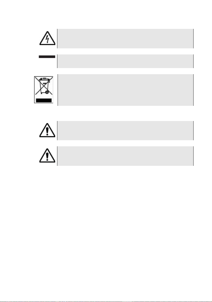
Table 3 Symbol conventions
This symbol represents a general hazard.
User Manual 78100000202 Rev. 003 xix
Page 20
About This Guide
Conventions
This symbol represents a risk of electrical shock.
NOTE
This symbol represents a Note indicating related information or tip.
This symbol, located on the equipment or its packaging
indicates that the equipment must not be disposed of in a landfill site or as municipal waste, and should be disposed of
according to your national regulations.
Table 4 Safety definitions
WARNI NG
Indicates a potentially hazardous situation which, if not avoided, could
result in death or serious injury.
CAUTION
Indicates a potentially hazardous situation which, if not avoided, may
result in minor or moderate injury.
xx User Manual 78100000202 Rev. 003
Page 21

Chapter1
8000 V2 Platform Overview
This chapter provides a general description of the 8000 V2 Platform.
Topics discussed in this chapter include the following:
– “Unpacking the instrument” on page 2
– “About the 8000 V2 Platform” on page 2
– “Main features” on page 3
– “Hard keys and indicators” on page 5
User Manual 78100000202 Rev. 003 1
Page 22
Chapter 1 8000 V2 Platform Overview
Fiber Optic
Transport Layer
Test
10G SDH / SONET /
Ethernet Test
CWDM / DWDM /
OSA
Unpacking the instrument
Unpacking the instrument
1 Remove the 8000 V2 Platform and its accessories from the packing
case.
2 Check that the module and accessories ordered are all there.
If any part is missing or damaged please contact your local Viavi agent.
The 8000 V2 Platform is delivered as standard with:
– A Getting Started Manual
– A mains adapter used for mains operation of the instrument and
battery charging
About the 8000 V2 Platform
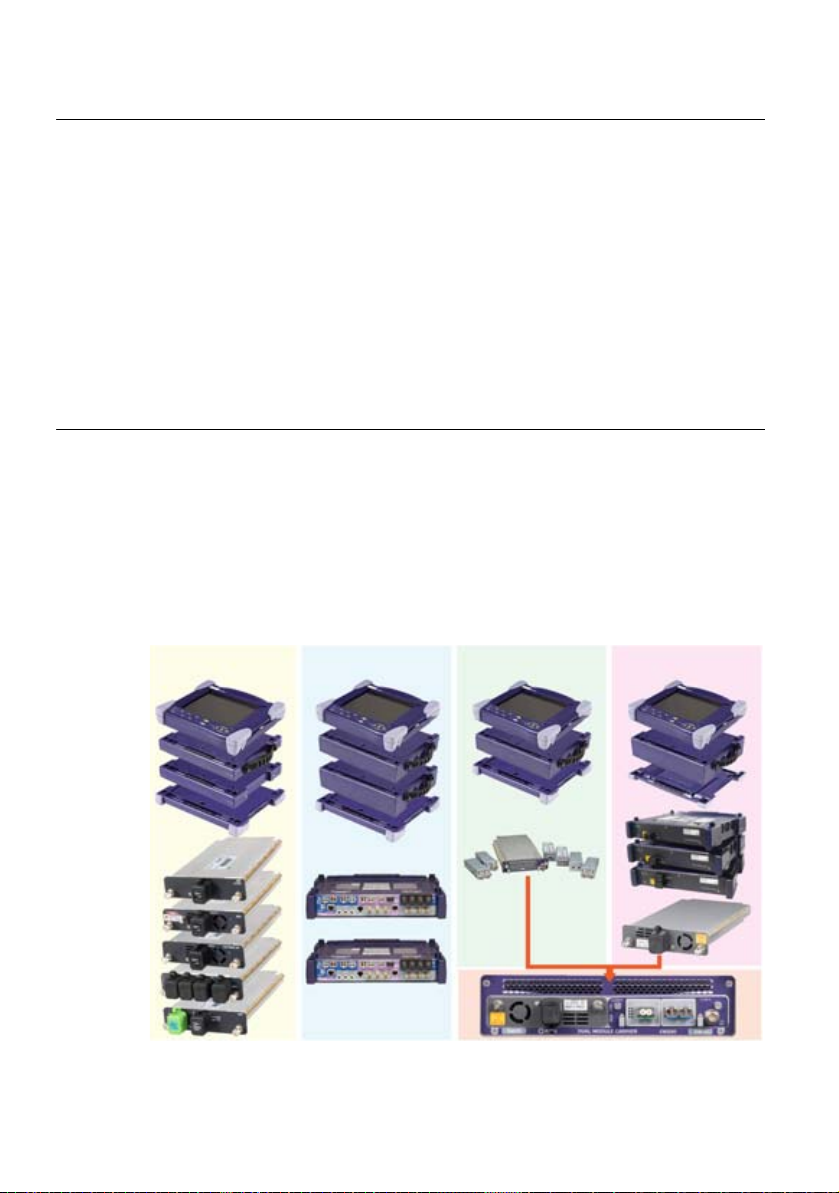
The architecture of the 8000 V2 Platform is based on the superimposition
of modules and receptacles to accommodate interchangeable plug-in
measurement units.
By the addition of modules and receptacles, a lightweight field instrument
can be converted into a complete apparatus with a high-level of performance and functions for the installation, maintenance and troubleshooting of fiber networks.
Fig. 1 Architecture of the T-BERD/MTS-8000 V2
2 User Manual 78100000202 Rev. 003
Page 23

Main features
Chapter 1 8000 V2 Platform Overview
Main features
Modules and plug-in units are easily interchangeable in the field,
reducing the number of instruments to be carried.
The 8000 V2 Platform employs multi-tasking for the simultaneous performance of several operations:
– acquisitions
– modifications of parameters
– trace analysis
– report management
It also allows to use simultaneously several functions:
– Power Meter
–Scope
– OTDR measurements...
The 8000 V2 Platform is equipped with the following elements:
– A 10.4 inch TFT color touchscreen, high visibility
– RJ45 plug for Ethernet interface
– Three USB 2.0 host connectors for Microscope, USB memory stick,
mouse, keyboard, ...
– One mini USB 2.0 device connector to connect the 8000 V2 Plat-
form
to a PC
– An audio jack to connect a headset
– A connection socket for the mains adapter providing the 24 V power
supply and used to charge the battery.
– LED indicators for Charge, On status and Test
– Up to two Li-Ion batteries (option)
– Built-in Power Meter, VFL and/or Talkset (options)
– A hard disk (option)
With the 8000 V2 Platform
, the user can:
– Open and/or transfer files to a PC via a USB memory stick, USB
cable or Bluetooth (option)
– Generate pdf reports
– Open all user documentations included into the 8000 V2 Platform
– Update the 8000 V2 Platform
User Manual 78100000202 Rev. 003 3
firmware
Page 24
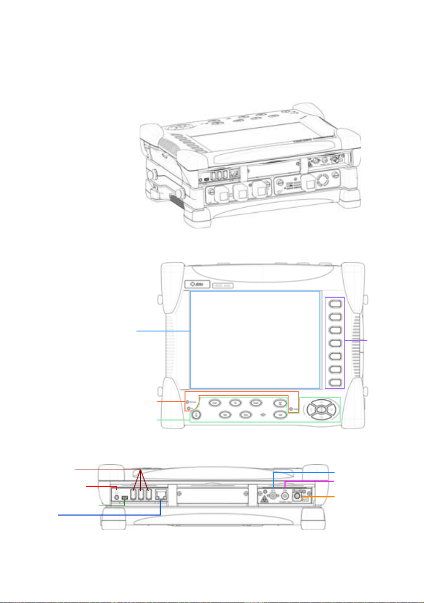
Chapter 1 8000 V2 Platform Overview
Hard keys
Indicators
Menu
keys
10.4’’ TFT
Touchscreen
USB host
Power Meter
VFL
Mini USB device
RJ45
Headset jack
Talkset
Main features
– Remote the screen of the 8000 V2 Platform onto a PC and issue
commands from the keyboard of the PC
–...
Fig. 2 MTS/T-BERD 8000 V2 with modules & Battery pack
Fig. 3 8000 V2 Platform - Front Panel description
4 User Manual 78100000202 Rev. 003
Fig. 4 8000 V2 Connectors - Upper view
Page 25
Hard keys and indicators
Front panel
hard keys
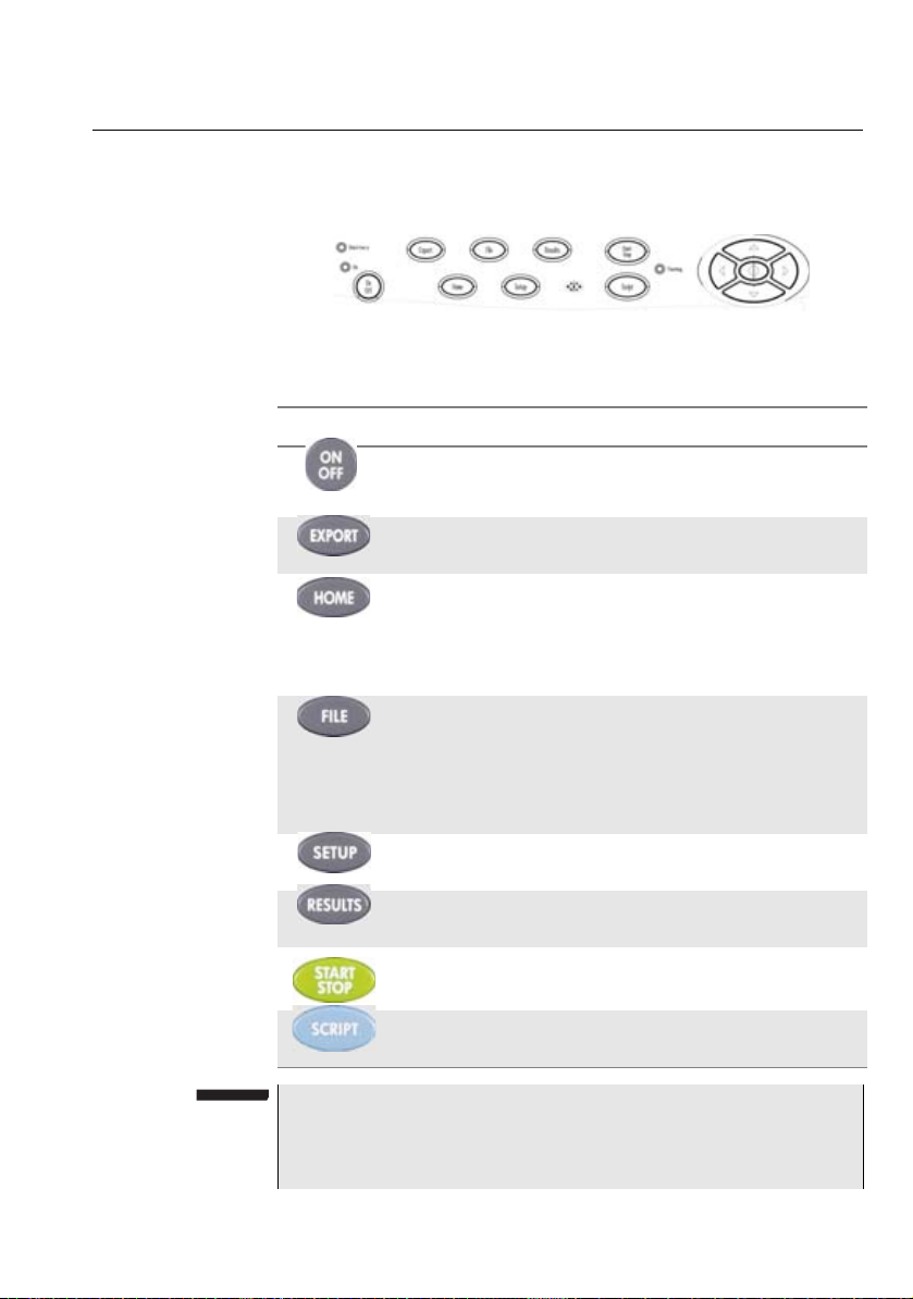
Fig. 5 Hard keys and Indicators
Table 5 Hard keys description
Hardkeys Function
Chapter 1 8000 V2 Platform Overview
Hard keys and indicators
Main on/off switch
This button allows to export the screenshot in a pdf/jpg/
png file.
Gives access to:
– selection of the different measurement or functions
– the settings of the instrument
– the help page
This button calls up the file explorer. It allows to:
– choose the storage medium: internal memory, USB
memory key...
– manage files; with facilities for classifying them in
directories and sub-directories.
This button calls up the measurement configuration
menu. This menu depends on the function in use.
This button calls up the results page (e.g. with OTDR
module: reflectometry trace and table of results).
Starts and stops the measurement.
This button is used to enter a sequence of commands
and execute it
NOTE
All these functions, except
the measurements made: refer to the user manuals of the corresponding modules of the 8000 V2 Platform.
User Manual 78100000202 Rev. 003 5
HOME, depend on the modules used and
Page 26
Chapter 1 8000 V2 Platform Overview
– on the Results page, they are used to move the cursors or
modify the zoom factor.
– on the set-up pages, they are used to scroll through the
menus, the central button serving to select or confirm the
parameter chosen.
Hard keys and indicators
The direction keys have two principal functions:
Front panel
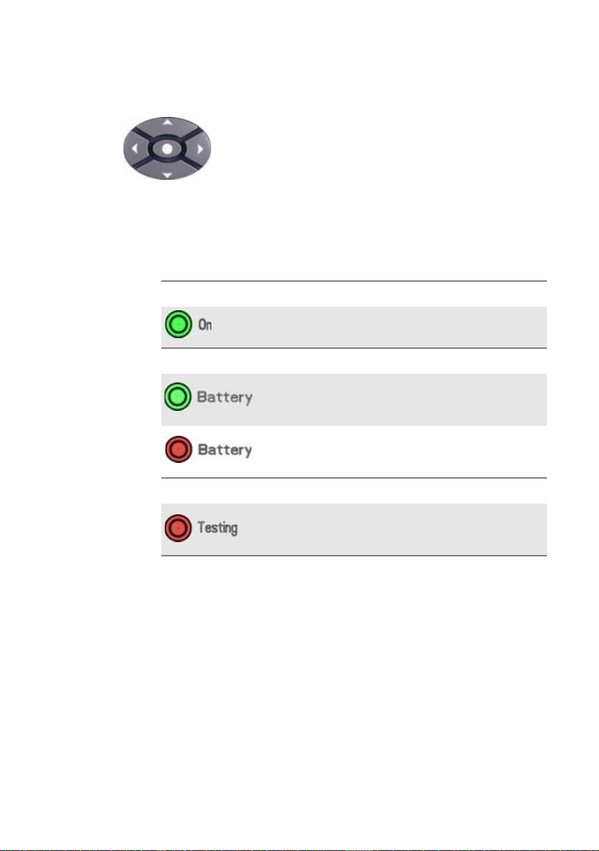
indicators
The 8000 V2 Platform is equipped with three indicators, lit into a different
color according to the status of the equipment.
Table 6 Indicators Status
On indicator
Solid green
The instrument is operating, either by
battery or on an external power supply.
Battery indicator
The instrument is connected to an
Solid green
Solid red
external power source and the battery
is fully charged.
The instrument is connected to an
external power source, and the battery
is on charge.
Testing indicator
At least one function is in measurement
Solid red
phase (for example, the laser emission
pilot for an OTDR measurement)
6 User Manual 78100000202 Rev. 003
Page 27

Chapter2
Safety information
2
This chapter gives the main information on the safety conditions when
using the 8000 V2 Platform:
– “Battery and AC/DC safety information” on page 8
– “Precautions relating to optical connections” on page 8
– “Laser Safety instructions” on page 9
User Manual 78100000202 Rev. 003 7
Page 28

Chapter 2 Safety information
Battery and AC/DC safety information
Battery and AC/DC safety information
– The Li-Ion battery is designed for maximum safety.
In particular, each cell is provided with a safety valve to prevent excessive internal pressure in the event of overcharging or exposure to very
high temperatures.
– Battery supplied by Viavi incorporate protection means.
Do not use any mains adaptor or battery other than those supplied with
the instrument, or supplied by Viavi as an option for this instrument.
If another adapter or battery is used, it may damage the 8000 V2 Platform itself.
Using the 8000 V2 Platform with a battery other than the one supplied by
the manufacturer of the 8000 V2 Platform may entail risks of fire or explosion.
The battery may explode, leak or catch fire:
– if it is exposed to high temperature or fire
– if it is opened or dismantled.
Other basic safety precautions are as follows:
– Do not use AC/Adapter/Charger outdoors or in wet or damp loca-
tions
– Connect the AC/Adapter/Charger to the correct mains voltage, as
indicated on the ratings label.
– Do not allow anything to rest on the power cord, and do not locate
the product where people can walk on the power cord.
– Avoid using this product during an electrical storm. There may be a
remote risk of electric chock from lightning.
– Do not use this product in the vicinity of a gas leak or in any explo-
sive environment.
– Do not attempt to service this product yourself, as opening or
removing covers may expose you to dangerous, high voltage points
and other hazards. Contact qualified service personnel for all
service.
Precautions relating to optical connections
– The normal operating life of an optical connector is usually of the
order of a few hundred manipulations. It is then advisable to manipulate the optical connections of the Platform as rarely as possible.
8 User Manual 78100000202 Rev. 003
Page 29
– The proper operation of the instrument and its accuracy of measure-
CLASS 1
LASER PRODUCT
LASER RADIATION
DO NOT STARE INTO BEAM
CLASS 2 LASER PRODUCT
LASER RADIATION - DO
NOT STARE INTO BEAM
CLASS II LASER PRODUCT
CAUTION
ment are dependent on the cleanliness of the environment and the
optical connectors as well as the care taken in its manipulation.
– The optical connectors must therefore be clean and dust-free. If the
optical connection is not being used, protect the connections of
8000 V2 Platform using the protective caps.
Laser Safety instructions
The provisions contained in two standards define the safety procedures
to be observed both by users and by manufacturers when utilizing laser
products:
– EN 60825-1: 2001 - Safety of laser products – Part 1: Classification
of products, requirements and user guidelines.
– FDA 21 CFR § 1040.10 - Performance standards for light-emitting
products - Laser products.
Due to the range of possible wavelengths, power values and injection
characteristics of a laser beam, the risks inherent in its usage vary. The
laser classes form groups representing different safety thresholds.
Chapter 2 Safety information
Laser Safety instructions
Laser classes
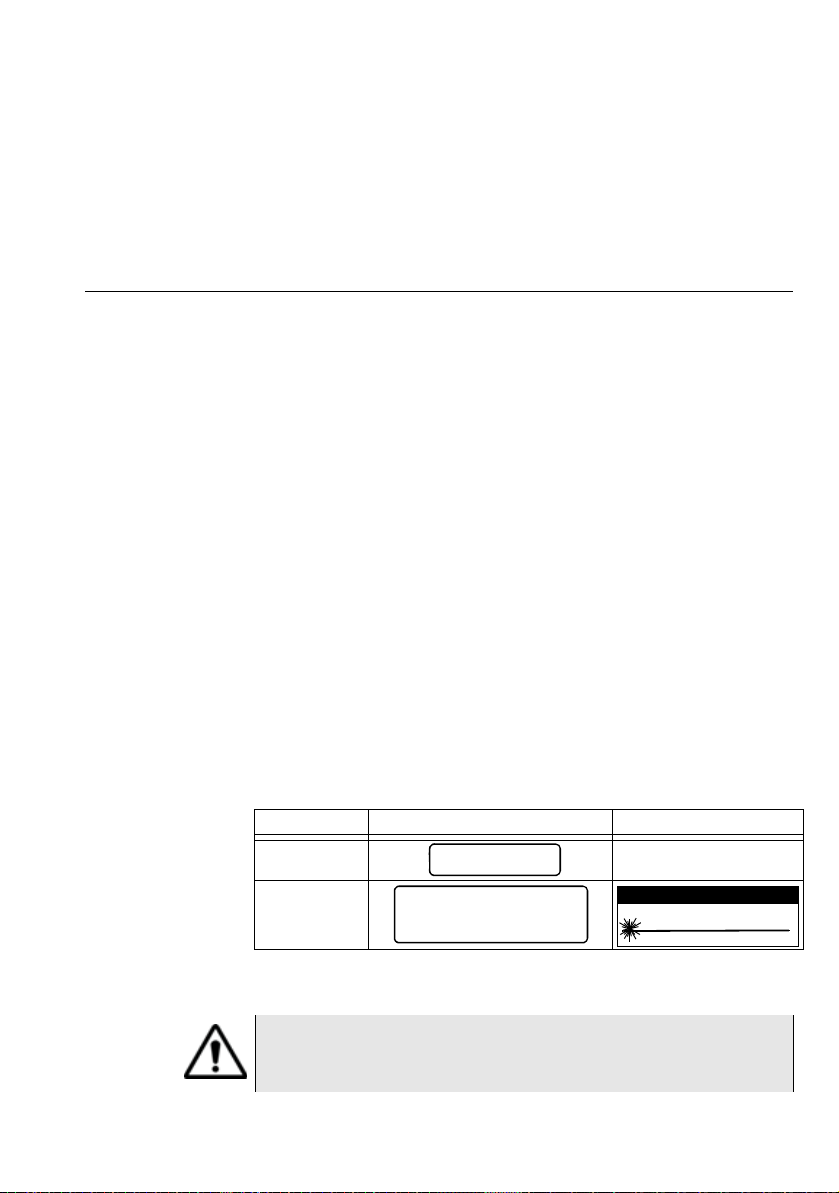
Warning labels
for the laser
classes
Standards EN 60825-1, Edition 1.2, 2001-08 and FDA21CFR§1040.10:
– VFL option: Class 2.
Due to the reduced dimensions of the optical modules, it is not possible
to attach the required warning labels to them. In line with the provisions
of Article 5.1 of the EN 60825-1 standard, the laser class identification
labels are shown below:
Ref. standard EN 60825-1, Edition 1.2, 2001-08 FDA21CFR§1040.10
Class 1
Class 2
The user must take the necessary precautions concerning the optical
output of the instrument and follow the manufacturer’s instructions.
Measurements on optical fibers are difficult to execute and the
precision of the results obtained depends largely on the
precautions taken by the user.
User Manual 78100000202 Rev. 003 9
Page 30

Chapter 2 Safety information
Laser Safety instructions
10 User Manual 78100000202 Rev. 003
Page 31

Chapter3
Starting up
3
This chapter describes the first steps to perform when using the 8000 V2
Platform.
The topics discussed in this chapter are as follows:
– “Fitting and removing a module carrier or a module” on page 12
– “Choosing the position of the instrument and fitting the carrying
handle/strap” on page 17
– “Charging the battery” on page 19
– “Switching the 8000 V2 Platform on and off” on page 21
User Manual 78100000202 Rev. 003 11
Page 32

Chapter 3 Starting up
Fitting and removing a module carrier or a module
Fitting and removing a module carrier or a module
The 8000 V2 Platform must be switched off, and if it is operating
on the mains, its supply cable must be unplugged.
Warning
Key principles
When connecting or disconnecting modules, focus on the following principles to ensure a secure connection and avoid damaging the connectors:
Alignment. Ensure that the holes on the corners of the Module or Battery
Module are aligned with the holes on the component you are attaching it
to. For example, if you are attaching the Optical Module to the base unit,
ensure that the holes of the module are aligned with the holes on the
base unit.
Parallel position. Ensure that you are holding the Module or Battery
Module in a position parallel to the base unit or Module (as illustrated in
Figure 9 on page 15). If either module is held at even a slight angle, there
is a risk of damage to the connectors.
Proper torque. Ensure that you tighten the screw using the hex key (for
the Module) or a flat blade screwdriver (for the Battery Module) until you
feel a slight resistance, and then tighten it using an additional 1/4 turn. If
you are using a torque wrench, apply 1.5 N-m (13.3 in-lb) to the final turn.
Required tools Large, flat blade screwdriver
You will need a large, flat blade screwdriver to remove and then replace
the battery module on the base unit.
Hex key (provided)
A 5 mm hex key is provided in a groove on the inside panel of the battery
module. This key is used to secure and then tighten the screws that
connect the module to the base unit.
12 User Manual 78100000202 Rev. 003
Page 33

Chapter 3 Starting up
Hex Key groove
Fitting and removing a module carrier or a module
Torque wrench (optional)
If you want to ensure that you don’t apply too much pressure when
connecting or disconnecting modules, you can optionally use a torque
wrench capable of applying 1.5 N-m (13.3 in-lb). A torque wrench with
the ability to apply up to 20 in-lb in 0.1 in-lb increments will be adequate.
You will also need a 5 mm hex key bit for the wrench.
Fitting a
module
Assembling the
instrument
Before installing or removing a module, review the key principles
provided below, and gather the proper tools.
To connect the Module and Battery Module to a base unit
1 Verify that power is OFF on your base unit and that the power
adapter is unplugged.
2 Using the large flat blade screwdriver, loosen each of the 4 slotted
bolts on the back panel of the battery module (attached to the base
unit), and then gently remove it from the base unit.
3 Remove the hex key from the groove on the inside panel of the
battery module. See Figure 6.
Fig. 6 Hex key groove in battery module
4 The base unit and the Module each have rectangular mating
connectors (see Figure 7 and Figure 8 on page 14). These connectors must be aligned carefully before connecting the module to the
base unit.
User Manual 78100000202 Rev. 003 13
Page 34

Chapter 3 Starting up
Base Unit Mating Connector
Module Mating
Connector
Fitting and removing a module carrier or a module
Fig. 7 Base Unit Mating Connector
Fig. 8 Module Mating Connector
To align the connectors properly:
14 User Manual 78100000202 Rev. 003
a Position the Module over the base unit, with the Module’s mating
connector directly over the mating connector on the base unit.
b Verify that the holes on each corner of the Module are aligned
precisely with the holes on each corner of the base unit.
c IMPORTANT: Risk of damage to connectors. Verify that you
are holding the Module in a position parallel to the base unit (see
Figure 9). If the module is tilted at even a slight angle, the
mating connectors may not connect properly, and you may
damage the connectors.
Page 35

Chapter 3 Starting up
Module or
Module Carrier
Base Unit
parallel position
align
align
1
2
3
4
Fitting and removing a module carrier or a module
Fig. 9 Proper alignment of Module and Base Unit
5 Slowly lower the Module until it is just over the holes on the base
unit, and then gently but firmly press the center of the module to
attach it to the base unit.
6 Starting at the upper right corner, do the following:
a Hex key. Using the hex key that you removed from the battery
module, tighten screws 1 through 4 (in the sequence illustrated
in Figure 10) until you feel a slight resistance.
b Hex key or torque wrench. Use the hex key to tighten each
screw one additional quarter-turn, or if you are using a torque
wrench, tighten each screw by applying an additional 1.5 N-m
(13.3 in-lb). Use the same sequence illustrated in Figure 10.
Fig. 10 Sequence for securing and tightening the screws
User Manual 78100000202 Rev. 003 15
Page 36

Chapter 3 Starting up
Fitting and removing a module carrier or a module
7 After the Module is secured to the base unit, put the hex key back in
the groove in the Battery Module, and then do the following:
a Position the battery module over the Module, with the battery
module’s mating connector directly over the mating connector
on the Module.
b Verify that the holes on each corner of the battery module are
aligned precisely with the holes on each corner of the Module.
c IMPORTANT: Risk of damage to connectors. Verify that you
are holding the battery module in a position parallel to the
Module, similar to that illustrated in Figure 9 on page 15. If the
module is tilted at even a slight angle, the mating connectors
may not connect properly, and you may damage the connectors.
8 Slowly lower the Battery Module until it is just over the holes on the
Optical Module, and then gently but firmly press the center of the
Battery Module to attach it to the Module.
9 Starting at the upper right corner, do the following:
a Using the large flat blade screwdriver, tighten screws 1 through
4 until you feel a slight resistance. Use the same sequence illustrated for the Module screws in Figure 10.
b Tighten each screw one additional quarter-turn in the sequence
illustrated in Figure 10 on page 15, or, if you are using a torque
wrench, tighten each screw an additional 1.5 N-m (13.3 in-lb).
The Module is connected to the base unit and can be used for
testing.
Removing the
Module
Disassembling the
instrument
16 User Manual 78100000202 Rev. 003
Before disconnecting the Module from the base unit, review the “Key
principles” on page 12 for assembling the instrument. The same princi-
pals apply when disassembling the various components.
The disassembling also requires the same tools as the assembling
process (see “Required tools” on page 12)
To remove the Module from a base unit
1 Verify that power is OFF on your base unit and that the power
adapter is unplugged.
2 Using the large flat blade screwdriver, loosen each of the 4 slotted
bolts on the back panel of the battery module (attached to the base
unit), and then gently remove the battery module.
3 Use the provided hex key to loosen screws 1 through 4 in the
sequence illustrated in Figure 10 on page 15.
4 Turn the base unit over so the display is facing upwards.
Page 37

Chapter 3 Starting up
Press Up Bumpers
Choosing the position of the instrument and fitting the carrying handle/strap
5 Disconnect the Module from the base unit by gently pressing
upwards on the two lower bumpers of the base unit as illustrated in
Figure 11.
Fig. 11 Bumpers (Base Unit)
IMPORTANT: When lifting the base unit, be certain to apply force
directly over the base unit mating connector (illustrated in Figure 7
on page 14). The lower bumpers are located on the front (display)
panel of the base unit, and they are parallel with the mating
connector provided on the bottom (connector) panel. In Figure 11,
the base unit mating connector is not visible; it is directly above the
mating connector of the Module.
6 After the base unit is completely disengaged from the Module, lift it
up further and place it elsewhere on your work surface.
The instrument is disassembled.
Choosing the position of the instrument and fitting the
carrying handle/strap
Setting the
standard stand
Depending on the conditions of use of the 8000 V2 Platform, the instrument may be placed on a flat surface or held in the hand.
User Manual 78100000202 Rev. 003 17
Page 38

Chapter 3 Starting up
«Standard»
stay
Optional
kickstand
Choosing the position of the instrument and fitting the carrying handle/strap
When used on a work surface, the 8000 V2 Platform should be supported
on its stand, which can be set in either of two positions, depending on
whether the user is standing or sitting.
To change the stand from “seated user” position to “standing user” position, press both sides to slide the stand towards the upper end of its
groove.
Installing the
kickstand
(option)
A kickstand may be installed on the 8000 V2 Platform, if the option has
been ordered with the equipment.
– To fit a kickstand, position each stud against the attachment point
provided for the purpose on the sides of the cover, and press.
Fig. 12 Platform on kickstand
– To detach a kickstand from the instrument, lift the stud away from its
attachment to open the internal clip, and pull.
Fitting the
carrying handle
or strap
18 User Manual 78100000202 Rev. 003
When the 8000 V2 Platform is used hand-held, the carrying strap may be
fitted instead of the handle.
The strap (or the handle) is fastened with quick-fitting attachments on
each side of the modules.
Page 39

– To fit a strap (or a handle), position each stud against the attach-
Fixing attachment for
carrying strap or
handle
Handle
Handle fixing
clip
Plug indicator (lit in green
when equipment is
connected to mains)
Battery indicators (lit in
orange when batteries are
not sufficiently charged)
Plug the mains adapter
ment point provided for the purpose on the sides of the cover, and
press.
– To detach the strap (or handle) from the instrument, lift the stud
away from its attachment to open the internal clip, and pull.
Fig. 13 Attachment of strap or handle
Charging the battery
Chapter 3 Starting up
Charging the battery
Connecting the
mains adapter
1 At the right side of the battery pack, lift up the power supply socket
protector and plug in the mains adapter.
2 Connect the adapter to the mains.
The On indicator lamp starts to blink in green.
The «plug» indicator of the battery pack lits in green.
Fig. 14 Mains plug and indicators on battery pack
User Manual 78100000202 Rev. 003 19
Page 40

Chapter 3 Starting up
Charging the battery
Use only the mains adapter supplied with the 8000 V2 Platform.
The adapter for some other electronic device may appear to be
identical, but entails a risk of damage to the 8000 V2 Platform.
Charging the
battery
Battery charge
level display
On connection to the mains:
– if the user does not press
case, the Battery indicator on the front panel will be lit in red.
– when the user presses the
battery will charge during use (Battery indicator on the front panel in
solid red).
Once the battery is fully charged, the Battery indicator is lit in solid green
on the front panel.
When the Battery indicator on the front panel is blinking red, this mean
the power supply is not compatible with the battery used. Charge is
disabled.
It is essential to wait until charging is complete to ensure
maximum independent operating time, which may otherwise be
considerably reduced.
When the battery is installed in the instrument, a battery icon is displayed
in the top right-hand corner of the screen. Example: .
When two batteries are set in the battery pack of the 8000 V2 Platform,
both battery icons are displayed on the upper banner, each one with its
charge level. Example: .
ON, the battery will start the charge. In this
ON key, the instrument starts up and the
Icon Battery charge level
From 100% to 70%
From 70% to 40%
From 40% to 10%
From 10% to 0%
– When the level becomes too low, the instrument emits a beep to
inform the user until it switches off automatically after saving the
current configuration and measurement.
20 User Manual 78100000202 Rev. 003
Page 41

Switching the 8000 V2 Platform on and off
Switching the 8000 V2 Platform on and off
Chapter 3 Starting up
Switching on
the 8000 V2
Platform
Switching off
the 8000 V2
Platform
1 Press the ON/OFF key.
If the Platform is powered to mains, the battery will charge.
The On indicator pass from blinking to solid green and the icon.
The Viavi logo appears on the screen briefly, then an autotest is
carried out.
The equipment is ready to be used once all the applications are
installed.
NOTE
It is possible to switch over from battery to mains operation, or vice
versa, without loss of data.
The module cannot be swapped when the unit is ON or AC
powered
In the event of an unexpected mains power cut, if there is no
battery, the current results and configuration will not be saved.
Next time the instrument is switched on, it will return to its initial
configuration.
While the 8000 V2 Platform is operating, press the ON/OFF button to
switch it off.
NOTE
When the instrument is switched off using the
results and configuration are saved. Next time the
pressed, they are recalled.
ON/OFF button, current
ON/OFF key is
Resetting the
8000 V2
Platform
If the 8000 V2 Platform freezes, prolonged pressure (about 4 s.) on the
ON/OFF key will reset the instrument
User Manual 78100000202 Rev. 003 21
Page 42

Chapter 3 Starting up
Switching the 8000 V2 Platform on and off
22 User Manual 78100000202 Rev. 003
Page 43

Chapter4
Configuring the 8000 V2
Platform
4
This chapter describes the operations for configuring the instrument.
The topics discussed in this chapter are as follows:
– “Displaying the System Settings screen” on page 24
– “Defining the regional settings of the system” on page 25
– “Defining the screen parameters of the 8000 V2 Platform” on
page 26
– “Defining the Audio parameters of the 8000 V2 Platform” on page 27
– “Defining the Automatic shutdown of the 8000 V2 Platform” on
page 28
User Manual 78100000202 Rev. 003 23
Page 44

Chapter 4 Configuring the 8000 V2 Platform
see "Installing a new
version of the software" page 165
see “Configuring the
parameters of screen
shots” page 110
and
"Configuring the
report" page 111
see “Transferring the
8000 V2 Platform
Interface” on page 91
see “Sending files by
mail” page 108
&
“Transferring files via
Bluetooth” page 147
Displaying the System Settings screen
Displaying the System Settings screen
To display the System Settings screen, you must:
1 Press the H
OME hard key to reach the Home page.
Fig. 15 Home page
2 Press the menu key System Settings to open the System
Settings screen.
24 User Manual 78100000202 Rev. 003
Fig. 16 System Settings page
Page 45

Chapter 4 Configuring the 8000 V2 Platform
Defining the regional settings of the system
Defining the regional settings of the system
When the 8000 V2 Platform is delivered, it is automatically configured
with the System Settings set by default in factory, especially the
language and date/time (Language: English / Date format: dd/mm/yyy /
Time format: 24 hours clock).
To modify the regional parameters in the System Settings page:
1 Click on Language and select the language to be used for the
equipment.
2 Click on Date and enter the current date, using the numeric keypad
displayed with the menu key Edit Number.
3 Click on Time and enter the current time, using the numeric keypad
displayed with the menu key Edit Number.
The date and time are displayed on the upper right side of the
screen.
or
Select Net Time parameter and configure date and time according
to a network (see “Net Time Synchronization” on page 25).
4 Click on Date Time Format and configure the following parameters:
– Date format: select one of the option dd/mm/yy or mm/dd/yy.
– Time format: select one of the option 24 hour clock or 12 hour
clock.
5 Once all parameters have been defined, press Exit menu key to exit
the System Settings page.
Net Time Synchronization
This parameter allows to configure the date and time of the Platform
according to a network.
– Dynamic Mode: the time is synchronized according to the local
network.
The two lines Server Name are displayed but cannot be modified.
– Static Mode: in this case, the time is synchronized to the network
server which is defined in the two following parameters.
On the parameter Address Type, select if the address of the server
which will be used for synchronisation is entered via its IP Address
or via the Server Name.
If IP Address is selected, enter one or two server addresses in the
following parameters. During synchronization, the first address will
always be used, but if a fail occurs, the second one will be used.
User Manual 78100000202 Rev. 003 25
Page 46

Chapter 4 Configuring the 8000 V2 Platform
Defining the screen parameters of the 8000 V2 Platform
If Server Name is selected, enter the name of the server, and if
necessary a name for second server. During synchronization, the
first server name will always be used, but if a fail occurs, the second
one will be used.
During synchronization, the icon displays for a few seconds.
If the network configuration is modified, synchronization may be
lost.
– None: the time is not synchronized according to a server. In this
case, the user can reset date and time himslef, using the fields Date
and Time.
Defining the screen parameters of the 8000 V2 Platform
In the System Settings page, the following parameters can be defined:
Backlight
Contrast
26 User Manual 78100000202 Rev. 003
1 Click on Backlight
2 Define the backlight level of the screen, using the left and right
direction keys, or clicking on Edit Number softkey and using the
keypad displayed.
– Min backlight level
– Max backlight level
If the 8000 V2 Platform is operating on battery, it is advisable to
choose a minimum lighting level, acceptable for the user, to keep
endurance as long as possible.
1 Click on Contrast
2 Select the type of environment into which the instrument is used:
– Indoor: to be selected when the instrument is used inside (see
Figure 16 on page 24)
– Outdoor: to be selected in order to optimize the readability of
the screen for an outside use.
: -5
: +5
Page 47

Chapter 4 Configuring the 8000 V2 Platform
Defining the Audio parameters of the 8000 V2 Platform
Fig. 17 Example of outdoor contrast
Screen Saver
Click on Screen Saver if you wish to activate a screen saver to the equipment, to extend the life of the battery, in case the
used for some time.
Instead of the normal screen, a small animated picture of the
Platform
To configure the screen saver:
1 Click on Delay and select the time of inactivity
is displayed on the blackened screen.
before the screen saver starts:
The parameter No deactivates the screen saver
function.
60s, 3 min, 5 min.
8000 V2 Platform is not
8000 V2
Defining the Audio parameters of the 8000 V2 Platform
In the Audio box of the System Settings screen, you can configure the
audio parameters according you are using a headset with the 8000 V2
Platform
1 Adjust the volume on the line Hands-free Volume using the left and
.
right direction keys, or the Numeric keypad (displayed with the
softkey Edit Number)
– Min volume for Hands-free function: 0
– Max volume for Hands-free function: 100
User Manual 78100000202 Rev. 003 27
Page 48

Chapter 4 Configuring the 8000 V2 Platform
Defining the Automatic shutdown of the 8000 V2 Platform
2 If a headset is used, adjust the volume on the line Headset Volume,
using the left and right direction keys, or the Numeric keypad
(displayed with the softkey Edit Number):
– Min volume for Headset function: 0
– Max volume for Headset function: 100
Defining the Automatic shutdown of the 8000 V2 Platform
The automatic shutdown function switches off the 8000 V2 Platform automatically if no operation has been performed and no key actuated for a
period selected from this menu. Work in progress is automatically saved.
The function for automatically switching off the 8000 V2 Platform
is available only on battery operation, to save the battery.
1 In the Utility box, click on Auto off parameter.
2 Choose a time after which the 8000 V2 Platform
automatically,
minutes.
Select No if the 8000 V2 Platform
is inactivity on the equipment.
if no action has been done for that period: 5, 10 or 30
must not be switched off, even if there
will be switched off
28 User Manual 78100000202 Rev. 003
Page 49

Chapter5
Power meter, VFL (Visual
Fault Locator) & Talkset
5
A variety of built-in optical options are available when ordering. See
references in Chapter 15 “Options and accessories”, for details.
The topics discussed in this chapter are as follows:
– “Connection to the power meter, VFL and Talkset” on page 30
– “Using the Power meter” on page 30
– “VFL Function” on page 35
– “Storing and reloading results” on page 36
– “Talkset/Datalink Function” on page 37
– “Remote screen function via Talkset” on page 39
User Manual 78100000202 Rev. 003 29
Page 50

Chapter 5 Power meter, VFL (Visual Fault Locator) & Talkset
Power meter
optical connection
VFL
Talkset optical
connection
Connection to the power meter, VFL and Talkset
Connection to the power meter, VFL and Talkset
Fig. 18 Optical connectors
The type of optical connector used for the power meter is UPP (Universal
Push Pull), which is compatible with all diameter 2.5 mm connectors (FC,
SC, ST, DIN, E2000, etc.)
Accuracy of measurements
A high degree of accuracy is often required. It is then necessary to
perform a preliminary calibration without the fiber under test to eliminate the losses due to connections as far as this is possible. To do
this, use the «Reference Value» function.
Using the Power meter
The power meter function is an option chosen at the time of order and
incorporated into the 8000 V2 Platform in the factory.
30 User Manual 78100000202 Rev. 003
To activate the function:
1 Press the
2 Activate the power meter icon of the Platform .
The effect of this action will to be to bring the power meter into use
and to display the Results page for Power Meter.
HOME button
Page 51

Configuring the
power meter
Chapter 5 Power meter, VFL (Visual Fault Locator) & Talkset
Using the Power meter
Configuring
measurement
parameters
The measurement parameters can be accessed with the SETUP key.
Fig. 19 Configuration of power measurement
Wavelength Selecting wavelength:
- Auto: the wavelength of the input signal will be
automatically detected and selected to perform
the measurement:
850, 980, 1300, 1310, 1420, 1450, 1480, 1490,
1510, 1550, 1625 or 1650 nm: measurement
performed at specified wavelength.
- User: choice of wavelength on the next line
User choice (if the User option was selected in the Lambda
line) enter the wavelength between 800 and
1650 nm, using the numeric keypad, displayed
via the Edit Value key..
Beep on Modulation Select if a sound must be heard when a
modulation occurs (Yes / No)
Unit Unit of power displayed:
- Watts, dBm for displaying absolute power
- dB for displaying a result relative to a reference
(link loss)
Reference level Select the reference value for the wavelength
selected. First select the wavelength, then press
the > key to access choice of the value
(+XXX.XX).
This reference is also automatically available, in
the Results page, using the
key.
Set as Reference
User Manual 78100000202 Rev. 003 31
Page 52

Chapter 5 Power meter, VFL (Visual Fault Locator) & Talkset
Using the Power meter
Attenuator compensation
Choice of level to be applied to the wavelength
chosen for measurement to compensate for the
loss due to the external attenuator (+XX.XX dB).
First use the direction keys to choose the
wavelength, then press > to access choice of
value.
NOTE
To copy a Reference Level or a Attenuator Compensator on all wavelengths, select the reference wavelength and click on Update for All
Wavel..
Configuring the
alarm parameters
of the power meter
Display of results and commands
Result of the
measurement in
progress
Alarm Activation of the Alarm function : any result below
the lower threshold or above the upper threshold
will be displayed in red on the Results page.
Min and max thresholds:
Choice of lower and upper thresholds for each
available wavelength, from -60 to +40 dBm.
NOTE
To copy one value of the Lower or/and Upper threshold for all wavelengths, select the reference value and click on Update for All
Wavel..
NOTE
A continuous push on direction keys increments the value by 10 dBm.
The results page called up by the RESULTS button, gives the information
relating to the measurement in progress, results previously saved and
the commands available for measurement and saving.
The power measured by the power meter is displayed in large characters, in the units selected in the
– the mode of transmission of the signal measured: continuous (CW)
or modulated to a frequency of 270Hz, 330Hz, 1KHz, or 2KHz.
– the wavelength of the signal measured.
– the reference level expressed in dB.
– the level of Attenuation Compensation.
SETUP menu, together with:
32 User Manual 78100000202 Rev. 003
Page 53

Chapter 5 Power meter, VFL (Visual Fault Locator) & Talkset
Results
of the
power meter
Using the Power meter
Table of results
For one and the same fiber, the power meter displays a table of 9 results
corresponding to the different possible wavelengths. The first 4 results
are displayed on the screen; to scroll through the other results, use the
direction key
tive power (in dB) and the reference level in dBm (if units = dB), together
with the mode.
– A measurement result is displayed in the table when the Keep
Result softkey is pressed.
– The Clear Table softkey orders deletion of all the results displayed
in the table.
– If the Alarm function has been activated, any result that exceeds the
selected thresholds appears in red in the table. Otherwise, results
are shown in the table in green.
– When the instrument is switched off, results present in the table are
saved.
. The table shows the power measured in dBm, the rela-
Fig. 20 Results and commands of the power meter
Commands of the
power meter
parameters
When the LTS function is selected, the following softkeys are available
on the results page:
Keep Result Saves the result on the corresponding line of the
table.
Clear Table Deletes all the results recorded in the table.
Pressing the Powermeter Config. key allows to reach the following
function:
Wavelength Allows to modify the wavelength to be applied
with the Power meter.
Unit Allows to modify the unit of power displayed (dB,
dBm, nW)
Zero Adjustment of the Zero value when the power
meter’s optical input is closed with a plug (a
validation is required).
User Manual 78100000202 Rev. 003 33
Page 54

Chapter 5 Power meter, VFL (Visual Fault Locator) & Talkset
Using the Power meter
Click on Exit to go back to the Results page.
Pressing the Pow. Reference key allows to reach the following function:
Standard Reference Selects the current result as reference value to
measure the attenuation of a link. This reference
is displayed under the measurement result until a
new reference value is chosen.
Jumper Reference This key can be pressed when a reference in
loopback mode must be performed (see 8100
Module Series User Manual).
The soft key Jumper Ref is displayed in grey and cannot be
activated if both power meter and Source are selected onto the
OTDR Module set into the Platform.
The power meter must be selected onto the Base-Unit, and the
Source onto the OTDR Module to activate the soft key and be
able to perform a reference measurement in loopback mode.
Performing a
measurement
Power
measurement
The power meter is started up as soon as the function is acti-
vated in the
Power measurement is automatically updated in consequence. The
value «<-60 dB» is displayed when the laser is switched off and if the
source output is looped on to the power meter input.
1 Connect the light source to be tested to the rear connector (see
"Connection to the power meter, VFL and Talkset" page 30).
2 In the
3 Press the
The result will appear in the results page and can be memorized in
the table (see "Table of results" page 33).
4 Press the
HOME menu.
SETUP menu, choose the units dBm, dB or Watts.
STAR T/STOP key to start the measurement.
STAR T/STOP key to stop the measurement.
Optical link loss Setting the zero value of the power meter
It is important to set the zero of the power meter before making any
measurements where accuracy is required, as the noise from the germanium photodiode fluctuates over time and with variations in temperature.
34 User Manual 78100000202 Rev. 003
Page 55

Chapter 5 Power meter, VFL (Visual Fault Locator) & Talkset
VFL Function
1 Fix the plug over the optical input of the power meter so that no light
can reach the photodiode of the power meter. If the zero adjustment
is made without this plug, an error message may be displayed, as
the photodiode will detect too much light.
2 In the Results page, press the Powermeter Config. > Zero soft key
and validate.
Carrying out the reference measurement
1 Fix the adapter corresponding to the jumper to the optical connector
of the power meter.
2 Connect the jumper between the input of the power meter and the
output of the source.
3 Configure the same wavelength on the source and the power meter.
The power measured is displayed in the results page of the power
meter.
4 Press the Pow Reference > Standard Ref soft keys to save the
result displayed as reference value.
Measurements on the fiber under test
After defining the reference value, proceed as follows to make the
measurement:
VFL Function
VFL connector
Visual Fault
Locator
function (VFL)
1 Fix the jumpers and connectors needed to connect the fiber to be
tested between the source output and the power meter input.
2 In the set-up menu, select dB units.
3 The power displayed in the Power Meter window corresponds to the
optical loss of the link tested. It can be displayed in the table (see
"Table of results" page 33).
The type of optical connector used for the VFL source is UPP (Universal
Push Pull), which is compatible with all diameter 2.5 mm connectors (FC,
SC, ST, DIN, E2000, etc.).
See Figure 18 on page 30 to visualize the VFL connector.
This function is used to emit a red light signal of frequency 1 Hz or in
continuous mode into a fiber to detect any defects in the dead zone of the
reflectometer, or to identify it.
User Manual 78100000202 Rev. 003 35
Page 56

Chapter 5 Power meter, VFL (Visual Fault Locator) & Talkset
Storing and reloading results
This function is suitable for short fibers (length < 5 km) or the first few
metres of a long fiber.
NOTE
Identification is facilitated by the blinking of light in the fiber.
To emit a light signal into a fiber:
1 Connect the fiber to the VFL port on the connectors panel.
2 Press the
The icons display on the upper banner of the screen.
The signal mode (1Hz or CW) of the VFL can be modified in the System
Settings page, in Utility > VFL Mode parameter.
HOME key and activate the VFL .
Storing and reloading results
File Setup
Storing results
Loading results
36 User Manual 78100000202 Rev. 003
Click on the button FILE to access the File setup. See the chapter «File
management» in the user manual «8100 modules series» for a complete
description of all parameters, options and description of the explorer.
In order to save the results of a measurement, click on FILE and select
Store trace. Two files are being saved :
– The first file is used with the 8000 V2 Platform and allows to retrieve
all measurement results. It is saved with the extension «.Lts».
– The second file is a ASCII file using tabulations to separate values.
It is saved with the extension «.txt» and can be opened by the 8000
V2 Platform. It has been designed to be used with a spreadsheet
program on a PC where it allows to retrieve all measurement results
and format them in a nice customized table.
In order to load the results of a measurement, select a file with the
extension «.Lts» in the file explorer (see the chapter «File management»
in the user manual for «8100 modules series»), click on Load.
The LTS tab is displayed with the loaded results in the table
Page 57

Chapter 5 Power meter, VFL (Visual Fault Locator) & Talkset
Talkset/Datalink Function
The option enables two operators at opposite ends of an optical link:
– To communicate along the fiber.
– To transfer data along the fiber.
Each end of the optical link must be provided with a 8000 V2 Platform
equipped with the Talkset option.
Talkset/Datalink Function
n
Talks et
configuration
Connections
NOTE
It is possible to use the talkset of the 8000 V2 Platform and to carry
out measurements at the same time, on a different fiber.
NOTE
It is possible to use the Data transfer feature while using the optical
telephone of the 8000 V2 Platform. Nevertheless, the data transfer
speed will be slightly decreased.
The talkset configuration is set in the System Settings screen, in the
Audio box (see "Defining the Audio parameters of the 8000 V2 Platform"
page 27)
At each end of the fiber:
1 Connect the fiber to the Talkset port of the 8000 V2 Platform, either
directly or through jumpers.
The Talkset connector is set with a FC adapter by default.
Fig. 21 Installation for Talkset use
2 A headset (with earphones and a microphone) supplied with the
option may also be plugged into the 8000 V2 Audio jack.
User Manual 78100000202 Rev. 003 37
Page 58

Chapter 5 Power meter, VFL (Visual Fault Locator) & Talkset
Talkset/Datalink Function
NOTE
Data transfer uses the same fiber as the optical telephone
Establishing
communication
On the caller 8000 V2 Platform, press the HOME button, then validate the
desired function:
– Tal kset (Optical Telephone): used to communicate via the
fiber.
– Datalink : used to transfer data along the fiber.
If the remote instrument is ready to receive (on standby), the Talkset icon
turns yellow, beeps are emitted, and
– the icon appears at the top of the screen: telephone communi-
cation can now take place.
– the icon appears at the top of the screen: data transfer can now
take place.
If the remote instrument is not ready to receive, the Talkset icon does not
change color and a message is emitted.
NOTE
The talkset icon is displayed on the top banner as long as communication remains established, letting the user know that the connection
is working.
When communication is established, the headset is automatically
enabled if plugged in. However, the loud speaker must be correctly
configured in the setup menu to work accordingly
NOTE
Data transfer varies according to the type of application you use. For
Fiber Optics for example, you can use the explorer. The distant 8000
V2 Platform will be shown just like a disk and all file and directory features can be used from and to that disk.
Adjusting
volume level
38 User Manual 78100000202 Rev. 003
The sound is transmitted to the earphones of the headset and, if this
function has been activated, to the speaker in the 8000 V2 Platform base.
To activate the base loudspeaker and adjust the volume:
1 Press the
2 Press System Settings key to reach the System Settings page.
3 In the Audio box, select Channele and define the communication
settings: Hands-free / Headset / Auto.
HOME key.
Page 59

Chapter 5 Power meter, VFL (Visual Fault Locator) & Talkset
Remote screen function via Talkset
4 According to previous configuration, adjust Hands-free Volume
and/or Headset Volume (from 0 to 100).
Disconnection
When communication is over, deactivate the Talkset/Datalink function
on one of the 8000 V2 Platform. This deactivation can be done by either
8000 V2 Platform.
Then, the fiber used for Talkset can be disconnected safely.
Remote screen function via Talkset
This enables an operator at one end of an optical link to take control over
another 8000 V2 Platform connected at the other end, using the fiber.
NOTE
Each end of the optical link must be provided with a 8000 V2 Platform
equipped with the Talkset option.
VNC configuration
Before it can be remote-controlled, the 8000 V2 Platform must be configured as explained in “Remote Screen” on page 92 .
Connections
At each end of the fiber (see Figure 21 on page 37): connect the fiber to
the Talkset port of the 8000 V2 Platform, either directly or through
jumpers.
Remote screen via VNC is done via the data transfer feature, and on the
same fiber as the optical telephone.
Establishing communication
On the caller 8000 V2 Platform, press the HOME button, then select and
confirm the Talkset option:
1 If the remote instrument is ready to receive (on standby), the Data
icon turns orange, beeps are emitted, and the icon appears at
the top of the screen: data transfer can now take place.
If the remote instrument is not ready to receive, the Data icon does
not change color and a message is emitted.
2 Click next on Expert tools, Remote Display, and on Switch to
remote screen.
User Manual 78100000202 Rev. 003 39
Page 60

Chapter 5 Power meter, VFL (Visual Fault Locator) & Talkset
Remote screen function via Talkset
Your screen is now fully replaced by the distant screen, and everything you do on your 8000 V2 Platform is in fact done on the distant
8000 V2 Platform.
An icon appears in the top banner of the 8000 V2 Platform.
A slight normal color degradation may be seen on the 8000 V2
Platform controlling a distant instrument.
End of a VNC session
In order to end a VNC session, you can:
1 Return to the menu Expert tools > Remote Display and click on
Return to local screen. (Recommended solution)
or
Deactivate the data function on either 8000 V2 Platform connected.
or
Set Remote screen to off (see “Remote Screen” on page 92)
2 Disconnect the fiber
NOTE
The VNC icon in the top banner of the screen lets you know at all
times whether you are in a VNC session or not.
40 User Manual 78100000202 Rev. 003
Page 61

Chapter6
Scope
6
The scope function is a hot-plug feature enabled directly when inserting
a Viavi scope supplied as an accessory (see "References of accesso-
ries" page 159).
The topics discussed in this chapter are as follows:
– "Scope feature" page 42
– "Installation of tips" page 42
– "Configuring the P5000i Scope" page 43
– "Starting up with the scope" page 47
– "Launching a test of the connector and fiber end-face" page 48
– "File menu" page 52
User Manual 78100000202 Rev. 003 41
Page 62

Chapter 6 Scope
QuickcaptureTM buttonInstantly captures
(and analyzes) fiber image
Focus Control
Latch lock
Squeeze both ends to release
Barrel assembly
USB 2.0
connector
6 FT COIL Cable
Inspection tip
Magnification Control
Scope feature
Scope feature
Overview
This feature enables you to verify that your optical connectors are in
perfect shape and very clean condition.
The P5000i Digital Probe Microscope is a portable handheld microscope
used to view and inspect both the bulkhead (female) and patch cord
(male) sides of fiber connectors as well as other optical devices, such as
transceivers.
The P5000i requires an FBPT inspection tip and is connected to the 8000
V2 Platform with a USB 2.0 connector.
Fig. 22 P5000i Probe components
Before using the P5000/P5000i scope, make sure the Bluetooth
option has not been activated, even once, after the start of the
MTS/T-BERD 8000 V2. If it has been activated, stop and restart
the equipment before using the P5000/P5000i Scope.
Installation of tips
The Pass/Fail analysis function on the 8000 V2 Platform can only be
used with certain inspection tips mounted on the P5000i.
Seven tips, patchcords and bulkheads types, are delivered with the
42 User Manual 78100000202 Rev. 003
Videoscope Kit (EDFSCOPE5KI) but many others can be used.
Page 63

Configuring the P5000i Scope
Chapter 6 Scope
Configuring the P5000i Scope
Scope
connection
Configuring the
Scope
1 Plug in your Viavi scope into a USB port from the 8000 V2 Platform.
2 Push the button
3 Validate the Scope function .
4 Connect probe with the fiber being inspected.
You may select this option while other options are already selected (e.g.
OTDR).
1 Press SETUP key to configure the test.
The following screen displays:
HOME
Fig. 23 P5000i Scope Setup
Test Profile
On the line Profile, select the Profile which will be used for the test of fiber connector:
– SM_UPC: Pass/Fail criteria for single-mode UPC connectors from
IEC 61300-3-35 standard.
– SM_APC: Pass/Fail criteria for single-mode APC connectors from
IEC 61300-3-35 standard.
– SM_PC: Pass/Fail criteria for single-mode PC connectors from IEC
61300-3-35 standard.
User Manual 78100000202 Rev. 003 43
Page 64

Chapter 6 Scope
Predefined
parameters for
naming files
Configuring the P5000i Scope
– MM_: Pass/Fail criteria for multimode connectors from IEC 61300-3-
Profiles contain the analysis parameters by which PASS/FAIL criteria are
determined.
Once the line is selected, you can also add a new profile, clicking on the
Add Button (see "Adding a new profile" page 46).
Tip (only with P5000i Scope)
On the line Tip, select the tip set onto the scope to connect fiber for
inspection.
Capture button (only with P5000i Scope)
This parameter allows to select the action of the Quick Capture button
onto the Scope (see Figure 22 on page 42):
Freeze & Test pressing the button will automatically perform a
Freeze image pressing the button onto the Scope will
Auto Center (only with P5000i Scope)
This parameter allows to select if the scope image must be centered on
screen (select Yes) or not (select No).
35 standard.
test of fiber and freeze the result
automatically freeze the live image.
File parameters
The File menu allows to enter a file name for saving scope test results.
1 On the line Filenaming, use the edition keypad, which will display
by clicking on the right arrow key, to enter a specific name for the
file. You can enter manually a name and/or use pre-defined parameters (Fiber Id, Cable Id, Locations...).
Fig. 24 Edition keypad for naming scope file
44 User Manual 78100000202 Rev. 003
Page 65

Chapter 6 Scope
Configuring the P5000i Scope
1 To add a logo to a report generated from test results, select Logo
parameter and press right direction key to display the file explorer
page and select the image which will be used as logo on the report
page (see “Generating a report” on page 52).
Click on menu key Load to validate the selection. The screen
returns to configuration page and displays the file path in the Logo
parameter.
2 The Fiber box allows to configure the fiber plugged to the scope.
On the line Fiber Id, enter a name for the fiber using the edition
menu displayed via the right direction key.
On the line Fiber Number, use the numeric keypad, which will
display by clicking on the right arrow key, to enter the fiber number.
On the line Change fiber Nbr, select if the fiber number must be
modified after each results saving:
No: the fiber number is not modified at each saving
Increment; the fiber number is automatically incremented at each
results saving
Decrement: the fiber number is automatically decremented at
each results saving.
Link Description
The information entered in the Link Description window concern the
editing and/or the modifications of the cable and fiber parameters.
– Cable Id: This parameter allows to enter an identification of the
cable, using the Edition menu.
– Direction: The direction shows if the acquisition has been made
from the origin to the extremity (A->B) or from the extremity to the
origin (B->A). Changing direction makes it possible, when different
extremities are handled, to see the parameters of the fiber for the
other extremity.
– Location A: The name of the Location A of the link may be entered
here.
– Location B: The name of the Location B of the link may be entered
here
– Company: Allows to enter the name of the company carrying out
the test.
– Operator: Use the right arrow key to enter the name of the operator
carrying out the test.
NOTE
All parameters of the Link Description box will appear in the pdf
report generated from a test results page (see Figure 29 on page 53).
User Manual 78100000202 Rev. 003 45
Page 66

Chapter 6 Scope
Information on
scope
Information on
active test result
Configuring the P5000i Scope
Press Exit to return to the Results screen of the scope.
Adding a new
profile
About page
Once the Setup screen of the scope is displayed, you can add a specific
profile which will be used for the test.
The profile must be created via FiberChek2
storage media of the MTS/T-BERD 8000 V2 (disk, or USB memory stick).
1 On the Setup screen, select Profile and press Add key.
2 On the explorer, select the file which will be used as profile (icon
; extension: .PRO)
3 Press Load.
Once loaded, the display goes back automatically to Setup screen.
4 Select the profile just loaded.
TM
, and stored on one
Removing a profile
1 In the Profile list, select the profile to be deleted.
2 Press Remove key, then Exit.
On the Setup screen, the softkey About, on the right of the screen,
allows to display information on scope and current test result displayed
(in Full Screen mode or mosaic mode - see “Mosaic Mode” on page 49).
1 Press About softkey to display a page as the following one:
46 User Manual 78100000202 Rev. 003
Fig. 25 About page
Page 67

Starting up with the scope
Focus level for
image sharpness
Once the FiberScope icon is validated:
Chapter 6 Scope
Starting up with the scope
Freeze mode
1 Press R
ESULTS hard key
Fig. 26 Example of the result using the P5000i scope
Use the Focus Control button onto the P5000i scope (see Figure 22 on
page 42) to adjust the image quality and sharpness.
Once the image is acceptable, you may freeze the picture. This feature
allows to store in memory the resulting picture.
Freezing a scope result does not store the picture in a file (see "File
menu" page 52). The result will be lost if the instrument is shut off, or if
more than 3 pictures are frozen (see "Mosaic Mode" page 49).
High Mag. / Low
Mag.
NOTE
The button set on the lead, or the QuickCapture™ on the P5000
allows to freeze the picture, and to launch a test (according to configuration in Setup page - see “Configuring the Scope” on page 43).
The High Mag./Low Mag. menu key allows to switch the display from High to Low magnification and vice-versa. This function is also available pressing the button directly on the P5000i (see Figure 22 on page 42).
User Manual 78100000202 Rev. 003 47
Page 68

Chapter 6 Scope
Test result in
High mag.
Summary of
Tes t r es u l ts
Launching a test of the connector and fiber end-face
Camera mode
If you are in Freeze mode, or in Mosaic mode, with a picture selected
(see “Mosaic Mode” on page 49), press Camera menu key to return to
live camera picture.
Use the focus control to adjust the focus of the image
Launching a test of the connector and fiber end-face
Launching a
test of the
connector and
fiber end-face
Once the display is correctly adjusted (magnification, sharpness...), a
test of fiber connector can be launched.
To launch the test:
1 Press Test key to launch the test of plugged fiber connector.
The test is completed:
– once the Led Testing is no more lit in red
– once the icon is no more displayed on the upper banner
– once a screen as the following one displays:
NOTE
To configure the Pass/Fail criteria, refer to “Configuring the Scope” on
page 43.
Fig. 27 Test results
48 User Manual 78100000202 Rev. 003
Page 69

Chapter 6 Scope
Zone C
Zone B
Zone A
Zone D
Launching a test of the connector and fiber end-face
A summary of test results is displayed on the right, upper part of the
screen.
– Zone A: represents the Core zone: it is
the area surrounding the core
– Zone B: represents the Cladding zone.
It surrounds the majority of the fiber
cladding.
– Zone C: represents the Epoxy ring.
– Zone D: represents the Ferrule/Contact
zone: it identifies a portion of the ferrule
near and around the fiber
NOTE
To return to a Live Camera image, press Live key; or press Full Scr./
Mosaic key to view both live image and test result.
In Mosaic mode (see "Mosaic Mode" page 49), the result of the test
only displays Pass or Fail information; the status of each zone is displayed only in
full screen mode.
Mosaic Mode
Overlay
The Overlay key allows, when selected, to display the limits of each zone
and to display with colors the defaults on the image.
When the key is unselected, the zones and defaults are not graphically
identified.
This function is also available in Mosaic Mode (see “Mosaic Mode” on
page 49).
It is possible to display only one picture in full screen (640 * 390 pixels)
or up to four pictures (320*180 pixels each, including the live camera
picture) in mosaic mode. Use the key Full scr./Mosaic to switch from
one mode to another.
User Manual 78100000202 Rev. 003 49
Page 70

Chapter 6 Scope
Position 1 :
Position 2: Snapshot
saved on disk : connector
Position 3 :
Connector before
being cleaned
Position 4 : JPEG image
Selected picture
Menu keys when Live
picture is selected
Launching a test of the connector and fiber end-face
Fig. 28 Mosaic mode
– You may select one of the pictures by clicking on it.
The selected picture is framed in green.
The tool bar on the right varies according to which picture is selected
(camera, or static scope picture):
Picture selected: Live
Tes t Allows to launch a (new) test of the connector
Freeze Allows to freeze the live image and to save it later
50 User Manual 78100000202 Rev. 003
Overlay Allows to display/hide the limits of each zone and
If all positions were taken, the picture that was once at the fourth position is unloaded from memory. Frozen pictures are lost, unless they
were saved on the internal memory.
High mag./Low mag. Allows to switch all the images from high to low
(see
“Launching a test of the connector and fiber
end-face” on page 48
on the disk. Once this key is pressed, the freeze
image is automatically set on Position 2.
)
the detected defaults on image from a scope test
result (see
“Overlay” on page 49).
magnification and vice-versa. This key is not
Page 71

Chapter 6 Scope
Launching a test of the connector and fiber end-face
available with jpg files other than those resulting
from scope application.
Picture selected: Image
Save Allows to save the selected picture in
the directory Scope, in the disk of the
Platform. Press Save key, enter a name
for the jpg file and validate. This key is
not available with jpg files other than
those resulting from scope application.
Comment Allows to add a comment to the
selected picture (see
comment” on page 51
Overlay Allows to display or hide the limits of
each zone and the defaults on image
from a test result (see
page 49
jpg images which do not result from
scope application.
High mag./Low mag. Allows to switch all the images from
high to low magnification and vice-versa. This
key is not available with jpg files other than those
resulting from scope application.
). This key does not work on
“Adding a
)
“Overlay” on
Loading a
picture
Adding a comment
A key Comment allows you to enter/modify a comment to your picture if
necessary. This comment appears at the bottom left of the picture.
The right bottom of the frozen picture also contains the date of the acquisition (where the picture was frozen).
NOTE
Both the comment and the date will be saved with the picture.
It is possible to retrieve and load a picture stored in the Scope directory
and display it in the Scope page.
1 Press the
2 Select Explorer.
3 Select the JPEG file to be loaded via the Explorer.
4 Click on Load.
Recognized pictures are images resulting from the Scope option and
saved on disk via the 8000 V2 Platform.
User Manual 78100000202 Rev. 003 51
FILE button.
Page 72

Chapter 6 Scope
File menu
File menu
Some pictures resulting from the Scope option may appear
nevertheless unrecognized, if they have been stored with a
different Scope application, or if the JPG file has been opened
and modified under another JPG editor.
Even though the JPG editor of the Scope function has been designed to
display Scope pictures in black & white, it is also possible to open any
JPG valid file and display in color the corresponding picture. That picture
is enlarged or shrunk to the size of the display (full screen or mosaic,
see."Mosaic Mode" page 49).
Saving the test
result in a jpg
file
Generating a
report
Once the test has been performed, and the result is displayed on the
8000 V2 Platform screen:
1 Press F
2 Click on Save key to save a jpg file of the test result on the disk of
3 On the edition keypad, enter the name of the jpg file
4 Press Enter to validate.
1 Check the correct test result is selected (framed in green in mosaic
2 Press the
3 On the edition keypad, enter the name of the pdf file and press
ILE key
the 8000 V2 Platform.
The file is automatically saved on the disk, in the directory Scope
(icon ).
mode).
FILE button, then the Report key
ENTER.
The report generation is completed once the icon is no more
displayed on the upper banner.
NOTE
The pdf report will be saved on the disk, in the directory Scope.
Display of the report
Once the report has been generated:
1 Press F
52 User Manual 78100000202 Rev. 003
ILE hard key
Page 73

Chapter 6 Scope
Logo, company & parameters selected in the
Setup page (see
“Configuring the Scope” on
page 43
)
2 On the right menu keys, press Load soft key.
3 In the File Explorer, select the pdf report just created.
4 Press Load.
File menu
Fig. 29 PDF report
User Manual 78100000202 Rev. 003 53
Page 74

Chapter 6 Scope
File menu
54 User Manual 78100000202 Rev. 003
Page 75

Chapter7
Applications
7
Several desktop applications are provided to you, thanks to the integration of free software released under the free licences (GPL, LGPL, BSB
or other). Their purpose is to bring more functionality to the 8000 V2 Platform. Viavi doesn’t provide any warranty or support regarding these
free software.
To access desktop applications, press the button HOME, and the soft key
App’s.
The topics discussed in this chapter are as follows:
– "Navigation and text edition in the Application pages" page 56
– "PDF viewer" page 57
– "Web browser" page 58
– "Text Editor" page 62
– "Calculator" page 63
– "Calendar" page 64
– "Contacts" page 73
– "eMail Application" page 76
– "File Explorer" page 85
User Manual 78100000202 Rev.003 55
Page 76

Chapter 7 Applications
Navigation and text edition in the Application pages
Navigation and text edition in the Application pages
Navigating into
an application
page
Entering text
Once one of the applications is selected, the corresponding page opens.
Whatever is the page, different methods can be used to navigate in the
screen and select one text field, one button...
With VNC, touchscreen or mouse connected to one USB port of the 8000 V2 Platform:
The easiest way to navigate is to directly click, with mouse or stylus for
touchscreen, on one text field / button to enter text / activate the button.
With the 8000 V2 Platform keys
When you can only use the Platform keys to navigate into a page, several
methods can be used:
– You can use the direction keys to reach a text field / a button one
after the other, by successive presses.
– You can, when they are available, press the menu key Cursor until
the wished text field / button is active, and then press Select to
select it.
Some pages from the applications menu require to enter text, number...
Five ways can be used to enter text
1 Enter text using an external keyboard which is connected to the
8000 V2 Platform via the USB port or using an external keyboard of
a PC connected to the Platform.
2 Enter text using the keyboard of the Application
a Select Keyboard on the key
A keyboard is displayed on the lower part of the screen
56 User Manual 78100000202 Rev.003
Page 77

Chapter 7 Applications
PDF viewer
Fig. 30 Keyboard of the Text Editor
b Use the arrow keys or the touchscreen to enter the text.
3 Enter manually the text when a touch screen is used
a Select Writing on the key
b Write the letter manually, using the stylus for touch screen
You can click on Tr ain , in order to draw each character on its cell.
This allow to store the characters with your writing characteristics, in
order to get the good letters when writing with the stylus.
.
PDF viewer
Opening a PDF
document
Interacting with
a PDF
document
The simplest way to open a pdf file is to press FILE. Select Explorer, look
for your file and then select Load to load the corresponding file. The file
opens automatically in the PDF viewer.
Another way used to open a pdf document is to press Home > App’s and
select the PDF Reader icon.
The PDF Reader opens but without document. To open a PDF
document, click on the icon , or press
select a document in the file explorer dialog box.
Once your document is open, you may browse through different pages
very quickly, zoom to a particular level, rotate the page... All these
features are available via buttons on the screen.
User Manual 78100000202 Rev.003 57
FILE hard key, and
Page 78

Chapter 7 Applications
Display the current page #
Go to 10 pages less
Go to previous page
Go to next page
Rotate the page
Go to 10 pages more
Change zoom level Open file
Exit PDF viewer
Web browser
Fig. 31 PDF Viewer Graphical User Interface
NOTE
You may scroll in all directions using the direction key pad of the 8000
V2 Platform or of an external keyboard, or by dragging the scroll bars
with touchscreen or mouse.
Web browser
Configuring the
Web access
Starting the
web browser
58 User Manual 78100000202 Rev.003
Before using the Web Browser onto the 8000 V2 Platform, check/modify
the proxy configuration in the System Settings page:
1 On the Home page, press System Settings menu key
2 Select Use proxy parameter in the I/O Interfaces box
– If Manual is selected, enter the Proxy Address using the edition
keypad
– If Auto is selected, enter the Pac Address using the edition keypad.
To access this application, on the HOME page click on the soft key App’s.
In the Application screen, activate Web Browser icon .
The web browser is launched.
Page 79

Fig. 32 Web Browser page
Chapter 7 Applications
Web browser
Opening an
internet page
Once the Web Browser is displayed, you must enter the internet address.
1 Set the cursor in the address bar:
a Use the mouse connected via USB port on the 8000 V2 Platform
or the mouse of the PC if the screen is deported via VNC application on the PC.
b Click on the softkey Mouse so that it becomes .
This allows to move the cursor toward the address bar, and to
turn from to .
2 Once the cursor set onto the address bar, enter the address:
a Using a keyboard connected to the 8000 V2 Platform USB port
or the keyboard of the PC with a deport of the screen via VNC,
enter the entire address of the site to be opened.
b If none keyboard is available, click on Keyboard to
display the virtual keyboard and enter the address clicking
directly on characters (see "Entering text" page 56).
3 Push hard key to validate.
The page opens
If an error message is displayed in place of the internet page, verify
the address you typed, or check the proxies configuration (see
"Configuring the Web access" page 58).
User Manual 78100000202 Rev.003 59
Page 80

Chapter 7 Applications
Web browser
Fig. 33 Internet page opened with the Web Browser
Navigation into
the Web
Browser
Using the
bookmarks
Creating
bookmarks
Once the Web Browser is open, push the key to display on the
right of the screen, the buttons used to navigate.
Icon Definition
Go to the previous or next page loaded
Refresh the actual page
Exit the Navigation menu
Once a page is opened, you can apply it a bookmark, in order to get a
shortcut toward this page.
Once the internet page for which a bookmark must be created is opened:
1 Click on .
A new tools bar is displayed on the right of the screen.
2 Click on the menu key Add to add a bookmark for the
current page opened.
3 Click on Edit to edit the bookmark, and modify if necessary
the name of the bookmark. Click on Ok to confirm the modification
or Cancel to cancel the modifications
60 User Manual 78100000202 Rev.003
Page 81

Chapter 7 Applications
Web browser
Fig. 34 Creation of bookmarks
– Click on to open the page of the bookmark selected in the list
– Click on to delete the selected bookmark from the list
– Click on to exit the bookmark menu and go back to the Web
Browser page.
Opening a PDF
document
Leaving the
web browser
PDF documents may be opened and read within the Web browser.
Please refer to "Navigation and text edition in the Application pages"
page 56 for more information about that application.
1 When you click on a link toward a PDF file, a dialog box during
loading is displayed.
2 Once loading is completed, click on Ok to open the pdf file.
Fig. 35 Downloading a pdf file
NOTE
The web browser will open a PDF document, not a URL including a
PDF file.
The PDF is also automatically saved on the disk of the 8000 V2 Platform.
Depending on how long you want to leave the web browser and on your
connection mode, you may:
User Manual 78100000202 Rev.003 61
Page 82

Chapter 7 Applications
Text Editor
Text Editor
– Leave the web browser running and switch to another task. To do
this, click on the
To go back, you must select again the Web Browser in the App’s
menu:
– The icon is valid
– The application will reopen much faster, and all your environ-
ment will be the same (last current page, possibilities to go
back...)
– Quit the application using the Web browser
on the
key .
The Text Editor application allows to enter text on the 8000 V2 Platform
and save it into a txt file
HOME button.
application menu: click
Text Edit or
page
To open the Text editor:
1 In the Home page, press the App’s key
2 In the Application screen, select the icon Text Editor.
The icon is framed in white
3 Press to validate the selection and open the Text Editor.
Fig. 36 Text Editor application
Once the text editor is open, enter text using the method you wish (see
"Entering text" page 56).
62 User Manual 78100000202 Rev.003
Page 83

Chapter 7 Applications
Select the folder
Enter file name
Save the file
Calculator
Saving the text
in a file
Once the text is entered, you can save it in a file onto the 8000 V2 Platform.
1 Click on File > Save or Save as...
2 In the dialog box, select the folder in which the file must be saved
3 Enter a name for the file with the file extension
be opened with the 8000 V2 Platform).
(.txt or .csv if it must
Fig. 37 Save file
4 Click on Ok to validate
The file is saved and still opened
– You can modify it and click on Save at any time
– If you modify the file and click on Save as....you can choose another
folder and/or another name
Press to exit the text editor and go back to the Applications page.
Calculator
Press
HOME to go back to the Home page, and keep the application
active.
A calculator can be displayed and used onto the 8000 V2 Platform.
1 In the Home page, press the App’s key
2 In the Application screen, select the icon Calculator.
The icon is framed in white
3 Press to validate the selection and open the Calculator
User Manual 78100000202 Rev.003 63
Page 84

Chapter 7 Applications
Calendar
Calendar
Fig. 38 Calculator
Press to exit the Calculator and go back to the Application page.
Press
HOME button to go back to the Home page, and keep the Calcu-
lator application active.
The Application page also allows to use a calendar, in order to enter
Notes, dates, events etc.
Display of the
calendar
64 User Manual 78100000202 Rev.003
1 In the Application menu, select Calendar icon using direction keys
2 Press to open the Calendar application
Fig. 39 Calendar
Page 85

Chapter 7 Applications
Enter a general
description of the
event
Select the start & end time
of the event
Enter the start & end
date of the event
using the calendar
Save the event
Select the calendar to which
this event belongs (see
“Create a new calendar”
page 66
)
Select this parameter if the
event lasts all the day
Calendar
The page displays by default the calendar for the current date, in the daily
mode.
The today date corresponds to the date entered in the System
Settings page.
Create an event
in the calendar
Once the Calendar application is active, whatever is the View displayed,
you can add events to the calendar.
1 To enter a new event, click on New button (or use the File menu and
select New).
The Event dialog box opens
Fig. 40 Calendar: create a new event
1 Enter the necessary information for this event on each available tab:
– Event tab: enter the event description, date and time (see Figure 40
on page 65)
– Details tab: The elements countained in this tab allow to define the
location of the event, to save this event into a category (see “Create
a category” page 66) and to enter a full description of it.
– Alarm tab; this tab allows to activate an alarm for this event. This
alarm will be activated some minutes before the event start time
(from 1 minute).
– Recurrence tab; this tab allows to assign a recurrence to the event;
it will allow to recall the event as long as necessary (daily, monthly
...),
2 Once all the necessary parameters have been entered for an event,
click on Save to save it in the calendar.
– The event will be underlined in the calendar or in the agenda.
User Manual 78100000202 Rev.003 65
Page 86

Chapter 7 Applications
Calendar
Create a
category
Create a new
calendar
The events saved in the calendar can be defined in a specific category
you can create.
To d o so :
1 In the Tool Menu, select Category
The dialog box opens
2 Enter a name for this category
3 Select a predefined color for this category,
or click on to define a new color.
4 Click on OK to validate the creation of the
category
This choice of colour will allow to distinguish the events according to the
category to which they belong.
You can also create one or several other calendars than the one defined
by default in the application. This calendar will be specific and will allow
to insert specific events.
To create a new calendar:
1 In the Calendar application, click on Menu key and select Tools >
Calendars
The Calendars page opens
Fig. 41 View existing Calendars
2 To add a new calendar to the existing ones, click on the icon .
A new box opens
66 User Manual 78100000202 Rev.003
Page 87

Chapter 7 Applications
Calendar
Fig. 42 Create a new calendar
3 Enter the Calendar Title, which will appear in the View page.
4 You can also give a description of this calendar (for which use it has
been created...)
5 You can select a parent of this calendar; another calendar which will
be used as model for this one.
6 Modify if necessary the colour of the calendar
clicking on the colour displayed, to open the colour
selector box.
The colour will be applied for all the events belonging
to this calendar.
7 Click on OK to validate the new colour
8 Select the type of calendar:
– Local:
– Subscribe: select this parameter in order to receive other calen-
dars from other users.
If Subscribe has been selected, enter the URL, Username and
Password to access the calendar. Enter also the recurrence of the
update for this calendar (x times per hour / day / week / month /
year).
– Publish: select this parameters in order to publish the calendar,
and allow other users to visualize it.
If Publish has been selected, enter the URL, Username and
Password to access the calendar.
9 In the New calendar box, click on OK once all parameters are vali-
dated.
The screen displays the list of calendars, including the one just
created.
If this is not the case, click on the icon .
User Manual 78100000202 Rev.003 67
Page 88

Chapter 7 Applications
Calendar
Fig. 43 New calendar in the list
Click to Edit the calendar (see Figure 42).
Click on to delete the calendar and reassign if necessary the events
to another one.
Views of the
calendar
Daily, weekly and monthly calendar
The calendar application allows to display different information on the
screen.
Once the calendar application is activated, the page displays by default
the daily calendar, with the today date.
To modify the view of the calendar, you can:
– Click as many times as necessary on the key View to display
successively a weekly calendar, a monthly calendar, an agenda, the
existing alarms or go back to the today calendar.
or
– Use the tool bar or the View menu and select the view to be
displayed:
– : weekly calendar
68 User Manual 78100000202 Rev.003
Page 89

Chapter 7 Applications
Fig. 44 Example of weekly calendar
– : monthly calendar
Fig. 45 Example of monthly calendar
– : today calendar (same display as a daily calendar)
Calendar
Agenda
Fig. 46 Example of daily calendar
– You can choose the date for which the calendar will be
displayed, by using the following fields: .
Once the date is entered, click on the weekly or monthly icon, to
display the calendar for the week/month to which the date belongs.
In the View menu, or on the toolbar, you can choose to display a agenda,
which will display a list of all the events registered for a defined period.
1 Click on the icon of the toolbar
User Manual 78100000202 Rev.003 69
Page 90

Chapter 7 Applications
Calendar
or
Select Agenda in the View menu
or
Click as many times as necessary on the View key to reach the
agenda screen
Fig. 47 View Agenda
2 Once selected, you will have to enter the period you want to display
on screen
For example, in the Figure 47, the agenda displays the events registered for 3 months, starting from the current date.
NOTE
The agenda for the period selected can also be displayed in sidebar
(see “Sidebar” on page 72).
Event menu
Whatever is the kind of calendar displayed, you can click on an event of
the calendar, which will open a menu with different available actions:
Fig. 48 Event menu
– Edit: allows to edit the event selected, and if necessary to modify its
parameters.
70 User Manual 78100000202 Rev.003
Page 91

Chapter 7 Applications
Calendar
– Delete: allows to delete the event selected. A confirmation will be
asked.
– Save: allows to save the event in a .ics format onto the disk of the
Platform, or on the usb key connected to the equipment, if any,
– Move to Calendar...: allows to modify the calendar to which the
event belongs. Click to open a sub-menu with all the calendars
available (see “Create a new calendar” on page 66).
– Calendar: allows to edit, save in a .ics format, delete, show exclu-
sively or hide the calendar to which the events belong.
Alarms
Once the alarms of past events have gone off, it is possible to display a
list of those alarms.
1 Click on the icon of the toolbar or select Alarm in theTool
menu or click on the alarms menu key .
A summary of the Alarms which have gone off displays.
Fig. 49 Alarms
You can click on Show Event to display the event in alarm.
Click on Acknowledge to remove the alarm for this event
Click on Acknowledge All at the bottom of the screen to remove all
the alarms of the screen.
Click on Dismiss to go back to the calendar view. In this case, if an
reccurence has been defined for the alarms, the Alarms screen will
display back each time a reccurence occurs.
User Manual 78100000202 Rev.003 71
Page 92

Chapter 7 Applications
Calendar sidebar
Calendar selector
sidebar
Agenda sidebar
Calendar
Sidebar
A sidebar can be configured, to display more or less information on the
calendar screen. Three elements can be displayed on the sidebar:
– Calendar: this displays a calendar of the month activated.
– Calendar Selector (displayed by default when application is
launched): this display a list of the calendars available, and allows to
show or hide the events belonging to the calendar(s)
– Agenda (displayed by default when application is launched): display
a list of all the events saved for a defined period (see “Agenda” on
page 73 to modify a period for the agenda).
If a Calendar is deselected in the Calendar selector sidebar, then
the events belonging to it will not be displayed either in the
calendar nor in the agenda sidebar.
To activate one or several sidebar(s):
1 In the View menu, activate Sidebar
2 Select Calendar and/or Calendar Selector and/or Agenda to
display the corresponding sidebar on the right of the calendar.
Fig. 50 Calendar with all sidebars
Calendar
– Once this calendar is displayed, you can click on one date to display
the corresponding calendar.
The display keeps the calendar mode selected (daily / weekly /
monthly) and then will display the day, week or month to which the
date selected belongs to.
– The dates in bold are those for which one or several events have
been defined.
72 User Manual 78100000202 Rev.003
Page 93

Chapter 7 Applications
Contacts
– The sidebar will not be displayed if a monthly calendar is activated.
– Click on the white dates to reach the previous or next month (or
select a month on the upper toolbar).
Calendar selector
– Select/deselect a calendar to display/hide the events belonging to it.
If a calendar is deselected, this will automatically remove the events
defined for this calendar from the Agenda sidebar and from the
calendar on the left of the screen.
Agenda
– The agenda displays the events with the color corresponding to the
calendar they belong to.
– Click on one event to display it in the daily calendar.
Exiting from the
calendar
application
Contacts
Add a contact
– Click on to exit the Calendar application and go back to Appli-
cations page.
or
Press
HOME key to reach the Home page, and keep the application
active.
The Contacts application, available in the App’s screen, allows to add
contacts for sending e-mail.
1 In the Application menu, select Contacts icon using direction keys
2 Press to open the Contacts application
3 To enter a new contact, click on the New menu key
A new dialog box displays
User Manual 78100000202 Rev.003 73
Page 94

Chapter 7 Applications
Contacts
Fig. 51 New Contact
NOTE
You can select the Keyboard or Writing function to enter text (see
"Entering text" page 56).
If a category is modified / added / deleted via the eMail application, it
will be automatically added / deleted in the Calendar application, and
vice versa..
4 In the tab Personal, enter general information concerning the new
contact (Name / Birthday date / Summary)
Click on the blank square in order to select an image on the explorer
and associate it to the contact.
5 The Details button opens a new dialog box allowing to select details
about the contact: Title (Dr, Mss, Mr, Dr...) / First name / Middle
name / Last name / Suffix (Jr., Esq., Sr., I, II...)
6 In the tab Location, define the contact personal and professional
addresses and phone numbers, as well as its mail addresses.
7 In the Notes tab, you can add information about the contact
8 In the Categories tab, click on the Categories button to define the
contact to a existing category; or create a new one and link the
contact to it.
NOTE
The categories available are the same as the calendar categories
available in the Calendar application (see "Create a category" page
66)
9 Once all the necessary information have been entered, click on
SAVE to store the contact in the application.
74 User Manual 78100000202 Rev.003
Page 95

Chapter 7 Applications
Contacts
Fig. 52 New contact
NOTE
When a contact belongs to a category, a circle with the colour corresponding to the category is displayed next to its name.
10 You can use the menu Categories at the bottom of the screen to
filter the contacts according to the category they belong to.
11 Use the Find field to quickly retrieve a contact entering its name,
address...
or
Click on the Find button to easily find a contact.
12 Click on the contact mail address to directly open the eMail applica-
tion and send him a message by e-mail
or
Click on the Email button (see "eMail Application" page 76).
13 Click on the Backup button to save the contacts in a xml file.
14 Double click on the contact name on the left list to edit and modify if
necessary the contact information.
15 Click on to exit the Contacts application and go back to
Applications page.
or
Press
HOME key to reach the Home page, and keep the application
active.
User Manual 78100000202 Rev.003 75
Page 96

Chapter 7 Applications
eMail Application
eMail Application
The eMail application allows to send and receive mail onto the 8000 V2
Platform. To open the eMail application:
1 In the Home page, click on the App’s button
2 In the Application page, select and validate the icon
The following screen is opened by default
Fig. 53 eMail: Folder List page
eMail.
Configuring an
e-mail account
76 User Manual 78100000202 Rev.003
In order to be able to send and receive e-mail onto the 8000 V2 Platform,
you must first create and configure the user account.
1 Once the Index page is displayed, click on one the Basic parameter
to start configuration (see step 1). In this case, the Account titled
Example-Account in the Account page will be modified (see
Figure 54 on page 77)
or
Click on Cancel to reach the Folder List page and click on
Accounts on the upper part of the screen.
A new screen displays with one account visible, used as example.
Page 97

Chapter 7 Applications
eMail Application
Fig. 54 Account page
2 Click on New button to create a new account (or on Edit if an
existing account must be modified).
The Page Index displays
Basic parameters
1 Click on Basic line to display the Basic screen and enter general
information on the account.
Fig. 55 Mail Account - Basic parameters
Enter the necessary information concerning the description of the
account:
– Name of account: enter the name for the new account.
–Select Set as Default to define this new account as the default one.
– Personal Information: In this box, enter the full name of the
account (optional), its mail address (mandatory) and the organization it belongs to (optional).
– Server Information
Select the Protocol to be used for the account configuration:
– POP3: Post Office Protocole
User Manual 78100000202 Rev.003 77
Page 98

Chapter 7 Applications
eMail Application
– IMAP4: Internet Message Access Protocol
– News (NNTP): Network News Transfer Protocol
– Local mbox file
– None (SMTP only): Simple Mail Transfer Protocol
CAUTION
Once the Protocol is selected, and the Apply key is pressed, if
you go back to the Basic page, you cannot modify the Protocol
previously defined.
According to the Protocol selected, the parameters available are
different.
POP3 and IMAP4 Protocols
– Server for receiving: enter the server address for the received
messages.
– SMTP server (send): enter the server address for the sent
messages.
– User ID: enter the user idenfier for accessing to the server
– Password: enter the password for accessing to the server
News (NNTP) Protocol
– News Server: enter the server address for the received messages
– SMTP server (send): enter the server address for the sent
messages.
– This server requires authentication: if the server needs authetica-
tion, select this parameter to activate if necessary the following one,
and to enter a user identifer and password.
– Authenticate on connect: this parameter can be activate exclu-
sively when the following one is selected.
– User ID: enter the user idenfier for accessing to the server
– Password: enter the password for accessing to the server
Local Mbox File Protocol
– Local Mailbox: Enter the name of your local mail box
– SMTP server (send): enter the server address for messages sent.
– Use mail command rather than SMTP server: select this param-
eter deactivate the previous one and activate the following.
– command to send mails
None (SMTP only) Protocol
78 User Manual 78100000202 Rev.003
Page 99

Chapter 7 Applications
eMail Application
– SMTP server (send): use this protocol in order to exclusively send
mails and not to receive them.
2 Once the Basic Page is completed, click on
account.
APPLY to validate this
Receive
parameters
1 In the page index, click on Receive and define the parameters for
the received messages.
Fig. 56 Mail Account - Receive parameters
In the upper box (POP3 in the figure), define the parameters available,
which are different according to the protocol defined in the Basic page
(see page 77).
NOTE
If the protocol None (SMTP) is selected in the Basic page, the
Receive page is inactive.
POP3
– Use secure authentication (APOP)
– Remove message on server when received: allows to delete the
messages from server after a period, which will be defined in the
following parameter, activated once this one is selected.
Remove after x days: enter the number of days after which
messages will be removed from the server.
– Receive size limit x KB: enter if necessary the maximum size
authorized for the revceived e-mail.
– Default inbox: if necessary, select another directory in which
received e-mail will be stored, clicking on Browse.
IMAP4
– Authentication method: select in the list, the method to be used:
Automatic/Login/CRAM-MD5/ANONYMOUS/GSSAPI/DIGEST-MDS
– IMAP server directory (usually empty):
User Manual 78100000202 Rev.003 79
.
Page 100

Chapter 7 Applications
eMail Application
– Show subscribed folders only
– Bandwidth-efficient mode (prevents retrieving remote tags):
NEWS (NNTP)
– Maximum number of articles to download:
Local Mbox file
– Default inbox
The following three parameters are available for all protocols:
– Filter messages on receiving: selecting this parameter allows to
«sort» the e-mail when received.
– Allow filtering using plugins on receiving: this parameter can be
activated exclusively if the previous one is selected, and allows to
filter messages using plug-ins.
– ’Get Mail’ checks for new messages on this account: this
parameter allows to check automatically the messages when Get
Mail button is activated.
2 Click on Apply to validate the Receive parameters.
Send parameters
1 On the Page index, click on Send and define parameters for the
messages sent.
Fig. 57 Mail Account - Send parameters
In the Header zone:
– Select Generate Message-Id (not available with IMAP4 Protocol)
– Select Add user defined header to insert a specific header for all
messages, and click on
In the Authentication zone:
– Select SMTP Authentication (SMTP AUTH) if you wish to add an
authentication to the mail access.
80 User Manual 78100000202 Rev.003
EDIT to select file and configure header.
 Loading...