

Page 1

Matrix Switch 17.1.1.4
User Guide
22 Nov 2016
Page 2

Notice
Every effort was made to ensure that the information in this manual was accurate at the time of printing. However, information
is subject to change without notice, and Viavi reserves the right to provide an addendum to this manual with information not
available at the time that this manual was created.
Copyright
© Copyright 2016 Viavi Solutions Inc. All rights reserved. Viavi and the Viavi logo are trademarks of Viavi Solutions Inc. (“Viavi”). All
other trademarks and registered trademarks are the property of their respective owners. No part of this guide may be reproduced
or transmitted, electronically or otherwise, without written permission of the publisher.
Copyright release
Reproduction and distribution of this guide is authorized for Government purposes only.
Terms and conditions
Specifications, terms, and conditions are subject to change without notice. The provision of hardware, services, and/or software
are subject to Viavi standard terms and conditions, available at www.viavisolutions.com/terms.
Specifications, terms, and conditions are subject to change without notice. All trademarks and registered trademarks are the
property of their respective companies.
Federal Communications Commission (FCC) Notice
This product was tested and found to comply with the limits for a Class A digital device, pursuant to Part 15 of the FCC Rules.
These limits are designed to provide reasonable protection against harmful interference when the equipment is operated in a
commercial environment. This product generates, uses, and can radiate radio frequency energy and, if not installed and used in
accordance with the instruction manual, may cause harmful interference to radio communications. Operation of this product in a
residential area is likely to cause harmful interference, in which case you will be required to correct the interference at your own
expense.
The authority to operate this product is conditioned by the requirements that no modifications be made to the equipment unless
the changes or modifications are expressly approved by Viavi.
Laser compliance
This device is a class 1 laser product.
Industry Canada Requirements
This Class A digital apparatus complies with Canadian ICES-003.
Cet appareil numérique de la classe A est conforme à la norme NMB-003 du Canada.
WEEE and Battery Directive Compliance
Viavi has established processes in compliance with the Waste Electrical and Electronic Equipment (WEEE) Directive, 2002/96/EC,
and the Battery Directive, 2006/66/EC.
This product, and the batteries used to power the product, should not be disposed of as unsorted municipal waste and should be
collected separately and disposed of according to your national regulations. In the European Union, all equipment and batteries
purchased from Viavi after 2005-08-13 can be returned for disposal at the end of its useful life. Viavi will ensure that all waste
equipment and batteries returned are reused, recycled, or disposed of in an environmentally friendly manner, and in compliance
with all applicable national and international waste legislation.
It is the responsibility of the equipment owner to return equipment and batteries to Viavi for appropriate disposal. If the
equipment or battery was imported by a reseller whose name or logo is marked on the equipment or battery, then the owner
should return the equipment or battery directly to the reseller.
Instructions for returning waste equipment and batteries to Viavi can be found in the Environmental section of Viavi web site
at http://www.viavisolutions.com. If you have questions concerning disposal of your equipment or batteries, contact Viavi WEEE
Program Management team at WEEE.EMEA@viavisolutions.com.
Technical Support
North America 1.844.GO VIAVI / 1.844.468.4284
Latin America +52 55 5543 6644
EMEA +49 7121 862273
APAC +1 512 201 6534
All Other Regions viavisolutions.com/contacts
email customer.care@viavisolutions.com
Support hours are 7:00 A.M to 7:00 P.M. (local time for each office).
Page 3

Table of Contents
Chapter 1: Getting Started............................................................................................7
Matrix overview................................................................................................................................7
Matrix technical specifications.................................................................................................... 9
How to connect Matrix to your network................................................................................ 11
How to set IPv4 network settings.............................................................................................11
How to set IPv6 network settings............................................................................................12
How to set the system time and date.....................................................................................12
Chapter 2: Layouts....................................................................................................... 14
Understanding layouts..................................................................................................................14
How to edit a layout................................................................................................................ 15
How to create an additional layout.....................................................................................15
How to activate a different layout......................................................................................16
How to import a layout............................................................................................................... 16
How to export a layout................................................................................................................17
Chapter 3: Ingress and Egress Ports.......................................................................... 18
How to connect ingress and egress ports.............................................................................. 18
How to connect a network port to a tool port................................................................18
How to connect many ports to the same rule................................................................. 19
How to define a tool port.......................................................................................................... 20
How to define a network port..................................................................................................20
How to set port link speeds....................................................................................................... 21
Chapter 4: Traffic Rules...............................................................................................22
Understanding rules...................................................................................................................... 22
How to create a rule................................................................................................................ 22
How to edit a rule.................................................................................................................... 23
How to apply a rule in an inactive layout......................................................................... 23
How to apply a rule in the active layout.......................................................................... 24
Page 4

Chapter 5: Traffic Filters............................................................................................. 25
How to create a filter...................................................................................................................25
How to bind a filter to a rule.................................................................................................... 25
How to edit a filter.......................................................................................................................26
Understanding filters and filtering...........................................................................................26
Chapter 6: User Accounts and User Groups.............................................................. 28
How to set a user authentication scheme............................................................................. 28
How to authenticate locally.................................................................................................. 29
How to authenticate using LDAP.........................................................................................29
How to authenticate using Active Directory....................................................................30
How to authenticate using OMS......................................................................................... 30
How to authenticate using RADIUS.................................................................................... 30
How to authenticate using TACACS+..................................................................................30
How to change the administrator password..........................................................................31
How to add users........................................................................................................................... 31
How to edit a user.........................................................................................................................31
How to import users.....................................................................................................................32
How to delete a user....................................................................................................................32
How to add a user group............................................................................................................32
How to edit a user group............................................................................................................33
How to delete a user group....................................................................................................... 33
Chapter 7: Replication.................................................................................................34
How to replicate network traffic..............................................................................................34
Understanding network traffic replication.............................................................................35
Chapter 8: Aggregation and Speed Conversion.......................................................36
How to aggregate network links..............................................................................................36
Understanding network link aggregation...............................................................................37
How to perform speed conversion...........................................................................................38
Understanding speed conversion..............................................................................................38
Chapter 9: Load Balancing......................................................................................... 40
How to load balance.................................................................................................................... 40
How to load balance by conversation................................................................................40
How to load balance by packet volume............................................................................. 41
Understanding the load balancing process............................................................................42
Chapter 10: Packet Deduplication............................................................................. 44
How to deduplicate packets...................................................................................................... 44
How to direct the Matrix to identify duplicate packets............................................... 44
How to enable packet deduplication in a rule................................................................. 45
Understanding packet deduplication.................................................................................. 45
Chapter 11: Packet Trimming...................................................................................... 47
How to trim packets.....................................................................................................................47
Chapter 12: Firmware.................................................................................................. 49
How to upgrade the firmware.................................................................................................. 49
Chapter 13: Licensing....................................................................................................51
Understanding the licensing process........................................................................................51
4 Table of Contents (22 Nov 2016) — Archive/Non-authoritative version
Page 5

How to request a new license............................................................................................... 51
How to re-license the appliance...........................................................................................52
Chapter 14: Troubleshooting...................................................................................... 53
Understanding logging in Matrix..............................................................................................53
How to view event logs......................................................................................................... 53
How to send Syslog messages..............................................................................................54
How to send SNMP traps.......................................................................................................54
Understanding log categories.................................................................................................... 55
Informational.............................................................................................................................. 56
Warning........................................................................................................................................58
Error.............................................................................................................................................. 60
Fatal...............................................................................................................................................67
Chapter 15: Service and Repairs.................................................................................68
How to handle sensitive data before and after repairs..................................................... 68
How to create a backup file..................................................................................................69
How to factory reset a connected Matrix.........................................................................69
How to factory reset a disconnected Matrix....................................................................70
How to restore the backup file............................................................................................ 70
How to transfer settings to a different Matrix..................................................................... 71
How to create a backup file................................................................................................... 71
How to restore the backup file.............................................................................................72
How to request a new license...............................................................................................72
How to re-license the appliance...........................................................................................73
How to decommission a Matrix............................................................................................74
Chapter 16: FAQ............................................................................................................75
SFPs.....................................................................................................................................................75
Which transceivers are supported?......................................................................................75
Can I mix the media type within a port block?............................................................... 75
Can I mix 1 Gb and 10 Gb within a port block?................................................................ 75
Does Matrix regenerate an optical signal?........................................................................76
Setup..................................................................................................................................................76
Can I use DHCP to configure IP addresses on Matrix?...................................................76
Is IPv6 support for the management port?...................................................................... 76
What time sync options are supported?............................................................................76
What third party databases for user authentication are supported?........................ 76
Can I connect any port to any port?...................................................................................76
Will Matrix link to a connection with on the RX signal connected?...........................76
I have several Matrix switches. Can I centrally manage them?................................... 76
Is DC power available?............................................................................................................ 76
“Invalid credentials” error when using DNS name.......................................................... 76
SNMP..................................................................................................................................................77
Can Matrix send SNMP traps?...............................................................................................77
Deduplication...................................................................................................................................77
Can I customize the deduplication fields?......................................................................... 77
What is the time gap used to identify duplicate packets?...........................................78
Table of Contents (22 Nov 2016) — Archive/Non-authoritative version 5
Page 6

What is the number of packets or memory buffer time for determining duplicate
packets?........................................................................................................................................78
Load Balancing................................................................................................................................78
How is a conversation defined when load-balancing?.................................................. 78
Understanding load balancing after link loss................................................................... 78
Latency.............................................................................................................................................. 78
What is the latency for Matrix?........................................................................................... 78
How far back in time can I view utilization or packet error tracking?.......................79
Index............................................................................................................................. 80
6 Table of Contents (22 Nov 2016) — Archive/Non-authoritative version
Page 7

Chapter 1: Getting Started
Learn how to Matrix operates and how it is installed. Then learn how to configure
its network settings and set the system time.
Matrix overview
The Matrix is a network management switch that can filter, de-duplicate,
trim and time stamp inbound traffic and replicate, aggregate, or load-balance
outbound traffic before sending it to your network and security monitoring
tools.
1
Page 8
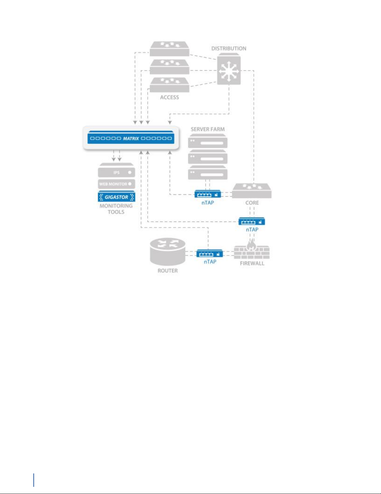
Figure 1: Matrix in your network
The Matrix can perform multiple operations on inbound data before it is
transmitted out tool ports:
♦ Filter traffic of interest to specific analysis devices: filters are
created using open source BPF Unix-based language and/or an intuitive
GUI interface. Filter traffic by variables, including clients or servers,
applications, packet length, or ports, and incorporate Boolean logic.
♦ De-duplication: eliminate redundant packets to streamline monitoring
efficiency and reduce the amount of redundant data sent, analyzed, and
stored. Configurable de-duplication definitions gives you options (for
example: ignore MAC address pair, TTL, and more) to create de-duplication
rules for your environment.
♦ Packet trimming: discarding portions of the packet, such as payload
data, for improved storage of data or to mitigate possible security/legal/
privacy concerns related to sensitive payload data retention.
♦ Flexible packet time stamping: use a variety of sources, including GPS
time synchronization, IEEE 1588 Precision Time Protocol (PTP), or Network
Time Protocol (NTP).
Matrix overview
8 Matrix (22 Nov 2016) — Archive/Non-authoritative version
Page 9
Outbound data can also be flexibly directed using:
♦ Replication (one-to-many): Copying a single inbound stream to multiple
tool ports, great for transmitting identical data to distinct monitoring
appliances
♦ Aggregation (many-to-one): Combining multiple streams of network
traffic into a single outbound stream for more efficient tool analysis
♦ Load balancing (many-to-many): Apply dynamic routing via packet or
conversation to logically distribute network traffic to multiple tool ports;
extending the life of legacy monitoring devices and ensuring traffic spikes
do not result in oversubscription and/or dropped packets
These capabilities are managed using a drag-and-drop GUI that accelerates
the Matrix configuration process by placing all traffic manipulation in a single
rule block rather than scattering it across inbound and outbound ports. It also
facilitates the display of network-tool interconnects and corresponding traffic
operations that makes even the largest, most complex monitoring infrastructure
straightforward to visualize and update. These rules are all managed in a central
library for use by the entire monitoring team and can be imported or exported.
Matrix provides three user or product interfaces:
♦ HTML5 web UI
♦ Command line interface (CLI)
♦ RESTful API: Designed into the product from its inception, the Matrix
RESTful API provides third-party solutions access to all the configuration
and management capabilities found in the web UI and CLI.
Matrix technical specifications
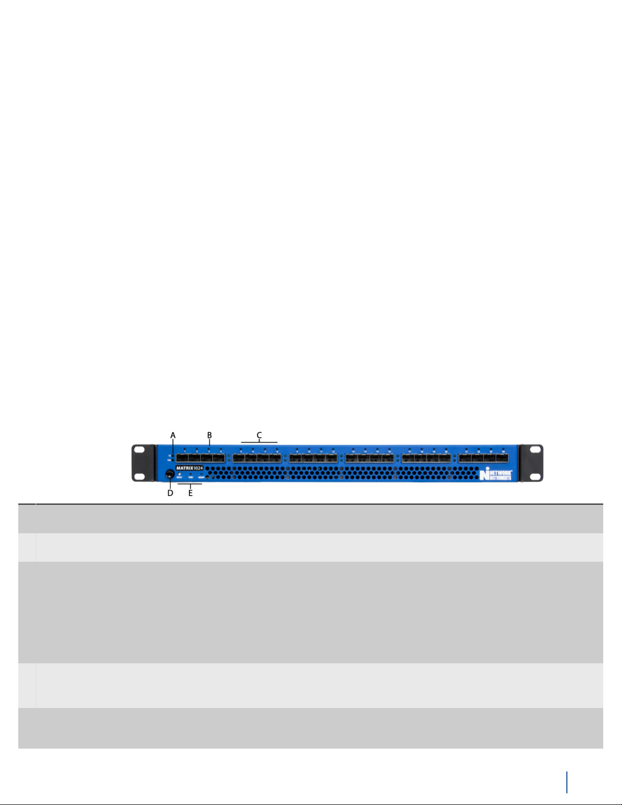
A Port Block
Speed
B Port Status Light that shows whether that specific port is active. When it blinks, there is traffic on the port.
C Port Block Group of four ports that are assigned a speed (for instance, 1 Gb or 10 Gb). All ports in the
D Power Press and hold for three seconds to turn the device ON or OFF.
E RESET/PWR/
MGMT
Light that indicates the speed for the port block. If no light is lit for the port block, that port
block is unlicensed.
The faster the blinking, the faster the traffic. When it is dark, the port is not enabled.
port block must be of the same speed; it cannot have mixed speeds. The 10 Gb licenses float,
meaning that if you insert a 10 Gb SFP+ into a port, that port block will be 10 Gb. If you license
two 10 Gb port blocks, the first two port blocks with 10 Gb SFP+s in them are licensed at 10 Gb.
If you insert a 10 Gb SFP+ into a third port block, it remains at 1 Gb and there will be a warning
in the logs and web interface. If you remove one of the first two 10 Gb SFP+s, the third port
block upgrades to 10 Gb. If you require mixed speeds, use 1 Gb in one port block and 10 Gb in a
different port block. You can then combine them using rules and filters.
To reset to factory defaults, unplug the power cables. Press and hold the Power button. While
holding the Power button, insert the power cable. Continue holding until the device beeps twice.
RESET: Reset button. Press to clear the memory and restart the device when the device is not
responding. Use instead of turning off or unplugging the device if there is a problem or before
restoring to factory defaults.
Matrix technical specifications
Chapter 1: Getting Started 9
Page 10
PWR: Power. When solid green, both power supplies are functioning as expected. When solid
orange, one of the power supplies is OFF or not functioning properly. Different from the PWR
light on the rear of the device.
MGMT: Ethernet (management) port. When solid green, an Ethernet cable is connected. When
unlit, no cable is connected and no changes can be made to the settings through either the web
UI or CLI.
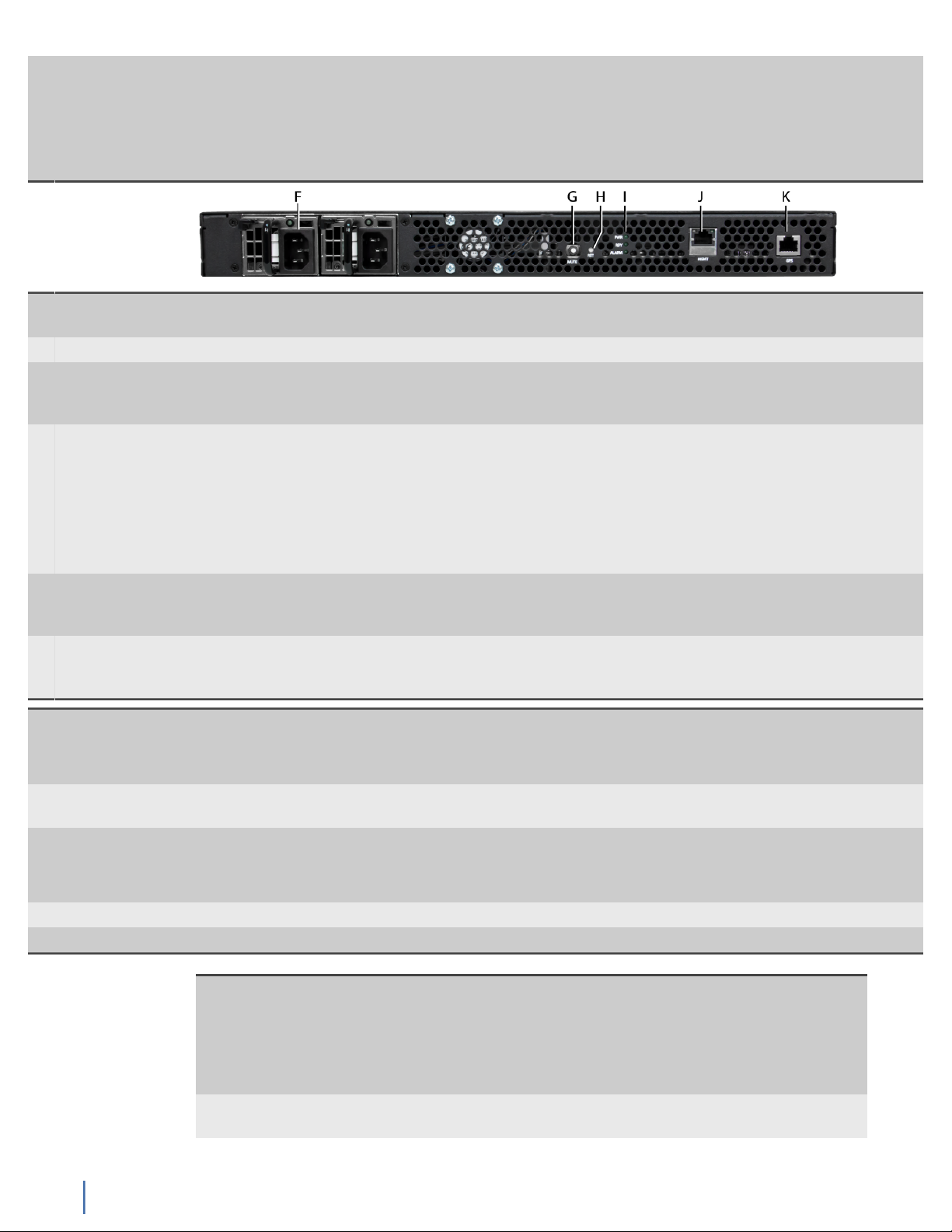
F Power
Redundant auto-selecting 100-240 volt power supplies are standard.
supplies
G MUTE Mute button to silence the alarm.
H RST Reset button. Use to clear the memory and restart the device when the device is not responding.
Use instead of turning off or unplugging the device if there is a problem or before restoring to
factory defaults.
I PWR/RDY/
ALARM
PWR: Power. Different than the PWR light on the front of the case and useful when
troubleshooting web or CLI interface connectivity issues. When solid green, the web and SSH
servers are running. When unlit, no power is present for those servers.
RDY: Ready. This light indicates that the web server and SSH server are running so that the web
UI and CLI are accessible. This light blinks during a factory reset; otherwise it is solid green.
ALARM: Alarm. When this green light flashes, the device is in an alarmed state (for example,
failed power supply). There are no current alarms if the light is dark.
J MGMT Ethernet (management) port. Used when configuring the device, which is done through the web
user interface (HTTPS) or command line interface (SSH). The left light is solid yellow when an
Ethernet cable is connected. The right light blinks green with activity.
K GPS Time
Port for attaching an optional Viavi GPS timing device.
Synchronization
System Port
Dimensions 19 in (W) x 1.73 in (H) x 18 in
48.26 cm (W) x 4.39 cm (H) x 45.72 cm
Power
consumption
Input voltage: 100V-240V auto select
Input frequency: 50/60Hz
93w (317 Btu/h)
Weight 17 lbs (7.7 kg) Supported
media
Operating
Temperature
32° F (0° C) to 104° F (40° C) Optical/Fiber Multimode or Single-mode
1 Gb (SX or LX)
10 Gb (SR, LR, ZR)
Humidity 35-85% (non-condensing) Copper 100/1000 Ethernet
1. Twinax cable must be 2 meters or shorter. Tested with Molex cables.
10 Gb Twinaxial (CX4)1
License The device is pre-licensed at the factory. The license enables
ports in blocks of four starting at port 1. It also indicates the
number of blocks that are 10 Gb-capable. If you have eight ports
licensed, you may only use ports 1-8. Ports 9-24 remain dark and
unusable even if you insert an SFP module. If you need more
ports or blocks of 10 Gb, you can request a license upgrade.
IP Address 192.168.1.10. Must use HTTPS in a web browser or SSH. HTTP will
fail.
Matrix technical specifications
10 Matrix (22 Nov 2016) — Archive/Non-authoritative version
Page 11

Default User/
password
Self-signed
certificate
admin/admin
Viavi uses a self-signed certificate. When connecting to the
device, your web browser may issue a warning about the site
being "untrusted" or that there is a problem with the "security
certificate." This is a harmless message that may be ignored. You
see that message because the site uses a self-signed certificate.
See your web browser's documentation for adding the IP
address as a trusted source.
How to connect Matrix to your network
Before you can configure or use the Matrix, you must complete the basic
installation by connecting power cables and inserting SFP modules.
1. Insert the two power cables (F).
2. Connect an RJ-45 Ethernet cable to the MGMT port (J).
3. Insert the SFP or SFP+ modules into the ports (C).
4. Connect the appropriate network cables to the SFP or SFP+ modules.
5. Press the Power switch (D) on the front of the device.
The PWR and MGMT lights turn green to indicate the device is ready to use.
You successfully connected the device to your network.
Next, change the network settings.
How to set IPv4 network settings
The Matrix must be added to your network like other devices. Use the network
settings page to set IPv4 settings for IP address and netmask, gateway, host
name, and more.
The Matrix is an active network device (unlike a typical optical TAP for instance).
The Matrix has a hardware address and requires an IPv4 address assignment to
join your network. However, IPv6 can optionally be enabled and used side-byside with IPv4—the matrix supports native dual-stack. Address assignments can
be manually configured or dynamically assigned using DHCP or DHCPv6.
1. Starting in the dashboard, click System.
2. Click Network.
3. In Hostname, type a host name for the Matrix.
4. (Optional) Use DHCP for address assignments:
a. Select DHCP.
The manual configuration settings become hidden.
b. Click Save.
DHCP is enabled. No further configuration is necessary.
5. In IP Address, type the IP address the Matrix must use.
6. In Netmask, type the full netmask associated with the chosen IP address.
7. In Gateway, type the IP address of the gateway the Matrix must use.
How to connect Matrix to your network
Chapter 1: Getting Started 11
Page 12

8. In DNS Address 1, type the IP address of a DNS server.
The IPv4 address of at least one DNS server is required. If two servers are
declared, the first server is used unless unreachable.
9. (Optional) In DNS Address 2, type the IP address of a DNS server.
10. Click Save.
You successfully added the Matrix to your network with IPv4 settings. The
changes take effect immediately.
How to set IPv6 network settings
The Matrix must be added to your network like other devices. Use the network
settings page to set IPv6 settings for IP address and prefix, gateway, host name,
and more.
The Matrix is an active network device (unlike a typical optical TAP for instance).
The Matrix has a hardware address and requires an IPv4 address assignment to
join your network. However, IPv6 can optionally be enabled and used side-byside with IPv4—the matrix supports native dual-stack. Address assignments can
be manually configured or dynamically assigned using DHCP or DHCPv6.
1. Starting in the dashboard, click System.
2. Click Network.
3. In Hostname, type a host name for the Matrix.
4. In the IPv6 Settings area, select IPv6.
5. (Optional) Use DHCPv6 for address assignments:
a. Select DHCPv6.
The manual configuration settings become hidden.
b. Click Save.
DHCPv6 is enabled. No further configuration is necessary.
6. In IPv6 Address, type the IPv6 address the Matrix must use.
7. In IPv6 Prefix, type the network prefix associated with the chosen IPv6
address.
8. In IPv6 Gateway, type the IPv6 address of the gateway the Matrix must use.
9. In IPv6 DNS Address 1, type the IPv6 address of a DNS server.
The IPv6 address of at least one DNS server is required. If two servers are
declared, the first server is used unless unreachable.
10. (Optional) In IPv6 DNS Address 2, type the IPv6 address of a DNS server.
11. Click Save.
You successfully added the Matrix to your network with IPv6 settings. The
changes take effect immediately.
How to set the system time and date
You can set or change how the current date and time is acquired. Doing
so ensures log events have correct dates and times and that packet trailer
timestamps are accurate.
How to set IPv6 network settings
12 Matrix (22 Nov 2016) — Archive/Non-authoritative version
Page 13

The Matrix must acquire its time and date from a clock source.
To set which clock source acquires the system time and date:
1. Starting in the dashboard, click System.
2. Click General.
3. In the Clock Source list under System Time Configuration, click a clock
source.
Clock source establishes the system time and is used for packet
timestamping.
Set now to browser time No configuration is necessary, but any system's
time is highly vulnerable to clock drift unless it uses an outside time
synchronization source.
IEEE-1588 IEEE-1588 is the Precision Time Protocol (PTP) specification. An
IEEE 1588-2008 server with an accurate time source can provide higher
resolution and accuracy than NTP. The IEEE 1588-2008 master time server
must be accessible on the same network subnet as the monitor port.
GPS Uses an external GPS connected to the GPS port on the rear of the
device. Only GPS Time Synchronization System appliances sold by Viavi
may be used. The GPS Time Synchronization System can provide the
highest resolution and accuracy.
NTP Synchronizing with Network Time Protocol servers or pools can
provide a low resolution, accurate time source. If NTP is chosen, one or
more NTP servers or pools must be defined.
If you select NTP, you must type an NTP server IP address in Server 1.
4. Click Save.
The clock source is set. Both the system time and date of the Matrix are set by
the selected clock source.
How to set the system time and date
Chapter 1: Getting Started 13
Page 14

Chapter 2: Layouts
Operation of your Matrix is configured in an arrangement called a layout. The
layout defines port connections, speeds, and the rules in use. You can also import
and export layouts.
Understanding layouts
2
Operation of your Matrix is configured in an arrangement called a layout. The
layout defines port connections, speeds, and the rules in use.
For most users, the default layout is sufficient. In the default layout, they will
set their port definitions, how network ports are connected to tool ports, and
which rules are used and do little else. However, you may want or need to have
additional layouts for prototyping.
Only one layout may be the active layout—with all other layouts being inactive
—and because changes made to layouts are effective immediately, carefully
consider any changes you make to your active layout.
Layouts are unlikely to change often, because after a layout is set and working,
there is little need to change it. However, something in your environment may
change that causes you to need to change your layout. Before changing the
active layout, you may want to prototype the changes in an inactive layout.
Creating a new layout is the only way you can design new port connections or
change port speeds and more without affecting active rules. In essence, a second
or third layout can be used as a sandbox to ensure options are configured as you
wish before moving the layout into production (in other words, promoted to be
the active layout).
Page 15

How to edit a layout
You can edit any layout without first activating it. This ensures any changes
made do not immediately affect operation of the Matrix while you edit the
layout.
Note: To edit the active layout (the layout currently in use), perform edits
directly from the Ports page. Edits to the active layout take effect in real
time.
To edit an inactive layout:
1. Starting in the dashboard, click Ports.
The layout designer appears, where connections between network and tool
ports can be created.
2. In the Layout list, select a layout.
3. Click the Actions list.
The Actions list is located near the top-right corner of the layout designer.
4. Click Edit.
5. Make your changes.
6. When you finish, close the Edit Layout browser window.
The layout automatically saves.
You successfully edited a layout without affecting the current operation of the
Matrix.
How to create an additional layout
You can create a layout to quickly and radically change how your Matrix operates
—similar to a preset. Rules and filters, which network ports are connected to
which tool ports, link aggregation, load balancing schemes, traffic isolation, and
more, can be simultaneously made active with a single change of a layout.
By default, the Matrix has an non-deletable layout named default. This default
layout can be the only layout your organization uses and needs—you make
changes to it and never use additional layouts. So although it is typically
unnecessary to do so, you can create additional layouts.
1. Starting in the dashboard, click Ports.
The layout designer appears, where connections between network and tool
ports can be created.
2. Click the Actions list.
The Actions list is located near the top-right corner of the layout designer.
3. Click Create New.
4. Type a name for the layout, and click OK.
A blank layout is created for editing. This is indicated by the new layout
having no tool port assignments.
Understanding layouts
Chapter 2: Layouts 15
Page 16

5. Assign at least one network port as a tool port by doing the following (repeat
for more):
Until you assign tool ports for use, no connections can be created between
network ports and tool ports. Because you can assign and reassign network
ports and tool ports at any time, do not place too much importance on
finding the right number of assignments immediately.
a. Double-click a network port.
b. In the Type list, select Tool.
c. (Optional) Type a name for the new tool port.
Giving names to ports can help when designing a layout. When naming a
port, consider the purpose of the port or the devices connecting to it.
d. (Optional) In the Speed list, click a speed setting.
6. When you finish, close the Edit Layout browser window.
The layout automatically saves.
You successfully created an additional layout. The new layout can be customized,
just as the default layout can be.
How to activate a different layout
After a layout is created, you can activate it at any time. Activating a layout
immediately changes how the Matrix operates.
Tip! Only activate a saved layout if you understand how the layout affects
the operation of the Matrix. Understanding the layout can help ensure
traffic is not forwarded to the wrong devices.
To switch which layout is currently active:
1. Starting in the dashboard, click Ports.
The layout designer appears, where connections between network and tool
ports can be created.
2. In the Layout list, select a layout.
3. Click the Actions list.
The Actions list is located near the top-right corner of the layout designer.
4. Click Activate.
The selected layout is now active. All connections, rules, filtering, and more, in
the layout are now actively in use.
How to import a layout
You can add a layout configuration by importing its file. The layout becomes part
of your library.
To import a layout file:
1. Starting in the dashboard, click Ports.
The layout designer appears, where connections between network and tool
ports can be created.
How to import a layout
16 Matrix (22 Nov 2016) — Archive/Non-authoritative version
Page 17

2. Click the Actions list.
The Actions list is located near the top-right corner of the layout designer.
3. Click Import.
4. Click Browse.
5. Browse to a previously exported layout file using the dialog box and click
Open.
6. Click OK.
You successfully imported the layout. The layout is now part of the Matrix and
can be activated, edited, saved, and deleted. The imported file does not need to
be kept.
How to export a layout
You can export a layout configuration for archival or backup, sharing, and
importing on other Matrix appliances.
To export a layout to a file:
1. Starting in the dashboard, click Ports.
The layout designer appears, where connections between network and tool
ports can be created.
2. In the Layout list, select a layout.
3. Click the Actions list.
The Actions list is located near the top-right corner of the layout designer.
4. Click Export.
A download begins in your browser.
5. Save the downloaded layout file to a suitable location.
You successfully exported a layout to a file. The file can be kept for archival, and
it can be imported by other appliances.
How to export a layout
Chapter 2: Layouts 17
Page 18

3
Chapter 3: Ingress and Egress Ports
A network port is an ingress port that accepts network traffic. A tool port is an
egress port that forwards network traffic to analysis tools. The connections must
be made between (ingress) network ports and (egress) tool ports before rules can
take effect.
How to connect ingress and egress ports
Connections must be made between (ingress) network ports and (egress) tool
ports before rules can take effect.
There are no dedicated ingress and egress ports in the Matrix; all physical ports
can assume either one of these roles. You, an administrator, can designate a
physical port as either a (ingress) network port or (egress) tool port by using the
web interface (dashboard) or command line interface (CLI).
How to connect a network port to a tool port
Connecting one network port to one tool port establishes a network path
between the two. Packets entering the network port are forwarded to the tool
port and any devices connected to it.
To connect a network port to a tool port:
1. Starting in the dashboard, click Ports.
The layout designer appears, where connections between network and tool
ports can be created.
2. Use a drag-and-drop operation to connect a network port to a tool port.
Successful connections are represented by lines between the ports and the
appearance of an empty rule. The empty rule is a placeholder for introducing
options such as filtering.
Page 19

You successfully connected a network port to a tool port. In this basic
configuration, assuming the empty rule is unmodified, every packet entering
the network port is forwarded to the tool port unchanged. And because the
connection exists, you can now introduce packet processing in the form of rules
—changing both how and what packets are forwarded to the tool port.
How to connect many ports to the same rule
Multiple network ports and tool ports can be connected to the same instance of
a rule. For example, doing so determines if aggregation or replication (or both)
are used in a layout configuration.
More than just for aggregation and replication of traffic, connecting multiple
ports to the same rule creates additional benefits:
♦ Ability to use load balancing
♦ Ability to apply the same filtering across several network links
♦ Ability to append packet trailers to packets arriving from various network
links
♦ Ability to resize ingress packets from multiple network links before
forwarding (packet trimming)
Note: To edit the active layout (the layout currently in use), perform edits
directly from the Ports page. Edits to the active layout take effect in real
time.
To connect multiple network ports or tool ports to the same rule:
1. Starting in the dashboard, click Ports.
The layout designer appears, where connections between network and tool
ports can be created.
2. In the Layout list, select a layout.
3. Click the Actions list.
The Actions list is located near the top-right corner of the layout designer.
4. Click Edit.
5. Use a drag-and-drop operation to connect a network port to a tool port.
Successful connections are represented by lines between the ports and the
appearance of an empty rule. The empty rule is a placeholder for introducing
options such as filtering.
6. Use a drag-and-drop operation to connect additional network ports or tool
ports to the same rule.
Depending on how many network ports or tool ports you connected to the rule,
the results are different:
♦ By connecting multiple network ports to the rule, you are aggregating
those network links.
♦ By connecting multiple tool ports to the rule, you are replicating traffic (if
load balancing is disabled).
How to connect ingress and egress ports
Chapter 3: Ingress and Egress Ports 19
Page 20

How to define a tool port
Tool ports forward post-processed traffic to the devices connected to them. You
must define which physical ports are to be used as tool ports.
There are no dedicated ingress and egress ports in the Matrix; all physical ports
can assume either one of these roles. You, an administrator, can designate a
physical port as either a (ingress) network port or (egress) tool port by using the
web interface (dashboard) or command line interface (CLI).
To define a tool port in a layout:
1. Starting in the dashboard, click Ports.
The layout designer appears, where connections between network and tool
ports can be created.
2. Double-click a network port.
Network ports are always located leftmost in a layout.
Options appear for this port.
3. In the Type list, click Tool.
The appliance ports can change modes of operation.
Network Port Ingress port that accepts network traffic
Tool Port Egress port that forwards network traffic to tools and analyzers
4. Click OK.
You successfully defined a tool port. When connections are made between it and
network ports, network traffic egresses from the port.
How to define a network port
By default, a new layout is comprised entirely of network ports. After
establishing some tool ports, you may want to change those tool ports back to
network ports in the future.
There are no dedicated ingress and egress ports in the Matrix; all physical ports
can assume either one of these roles. You, an administrator, can designate a
physical port as either a (ingress) network port or (egress) tool port by using the
web interface (dashboard) or command line interface (CLI).
Note: These steps require at least one tool port is defined in the layout.
To define a network port in a layout:
1. Starting in the dashboard, click Ports.
The layout designer appears, where connections between network and tool
ports can be created.
2. Double-click a tool port.
Tool ports are always located rightmost in a layout.
Options appear for this port.
3. In the Type list, select Network.
The appliance ports can change modes of operation.
How to define a tool port
20 Matrix (22 Nov 2016) — Archive/Non-authoritative version
Page 21

Network Port Ingress port that accepts network traffic
Tool Port Egress port that forwards network traffic to tools and analyzers
4. Click OK.
You successfully defined a network port. When connections are made between it
and tool ports, network traffic is forwarded to tool ports.
How to set port link speeds
You can set the link speed of ports to better accommodate connected devices.
Doing so is particularly useful when a 10 Gb optical SFP+ needs to interface with
a 1 Gb optical device, for example.
To set the port link speed of a network or tool port:
1. Starting in the dashboard, click Ports.
2. Right-click a port.
3. In the Set Speed submenu, click a speed setting.
The port is operating at the chosen speed.
The entire four port block now operates at the chosen speed.
How to set port link speeds
Chapter 3: Ingress and Egress Ports 21
Page 22

Chapter 4: Traffic Rules
Rules modify how and what packets are forwarded from network ports to tool
ports. Rules contain filters and set options like trailers, load balancing, and packet
deduplication, but rules only take effect when connected to ports.
Understanding rules
4
Rules modify how and what packets are forwarded from network ports to tool
ports. Rules contain filters and set options like trailers, load balancing, and packet
deduplication, but rules only take effect when connected to ports.
A rule is necessary to establish connections between network ports and tool
ports. Without a rule to establish the connection, no packets entering network
ports can be forwarded to tool ports. This convention applies to all connections
between network ports and tool ports regardless of how you design your
layouts.
At minimum, a working network path between a network port and tool port can
be made by connecting both ports to an "empty" rule. Empty rules establish a
connection yet do not change the behavior of what is forwarded to tool ports
and what ultimately egresses from them.
How to create a rule
You can create a rule to control how connected network ports and tool ports
interact. Use the rule to establish filtering and other options like load balancing,
packet deduplication, and more.
Tip! A new, empty rule is created by connecting a network port to a tool
port. This is a shortcut for creating new rules.
Page 23

To create a rule:
1. Starting in the dashboard, click Rules.
The rules and filters designer appears, where rules and filters can be created
and edited.
2. Ensure the Rules tab is selected.
3. Click New.
The rule opens and is ready to edit.
4. Make your changes.
5. Click Save.
You successfully created a rule. Whenever this rule is used to connect network
ports to tool ports, the logic is applied.
How to edit a rule
You can edit a rule to change which filter is bound to it or to configure options.
Tip! You can also edit by double-clicking rules in a layout.
To edit a rule:
1. Starting in the dashboard, click Rules.
The rules and filters designer appears, where rules and filters can be created
and edited.
2. Ensure the Rules tab is selected.
3. Click a rule from the list.
The rule opens and is ready to edit.
4. Make your changes.
5. Click Save.
You successfully edited a rule and saved the changes. If the rule is in use by the
active layout, the changes take effect immediately.
How to apply a rule in an inactive layout
Applying a rule between established connections in an inactive layout causes the
rule to take effect whenever the layout becomes active. Doing so changes how
and what packets are forwarded to tool ports connected to the rule.
Prerequisite(s):
These steps require that at least one rule (empty or otherwise) exists in the
target layout.
Tip! A new, empty rule is created by connecting a network port to a tool
port. This is a shortcut for creating new rules.
To apply a rule in an inactive layout:
1. Starting in the dashboard, click Ports.
The layout designer appears, where connections between network and tool
ports can be created.
Understanding rules
Chapter 4: Traffic Rules 23
Page 24

2. In the Layout list, select a layout.
3. Click the Actions list.
The Actions list is located near the top-right corner of the layout designer.
4. Click Edit.
5. Right-click a rule.
6. In the Apply Rule submenu, click Select and click a rule.
All of your created rules are in this submenu.
7. When you finish, close the Edit Layout browser window.
The layout automatically saves.
You successfully applied a rule in an inactive layout. When the layout is made
active, your rule takes effect.
How to apply a rule in the active layout
Applying a rule between established connections in the active layout causes the
rule to take effect immediately. Doing so changes how and what packets are
forwarded to tool ports connected to the rule.
Prerequisite(s):
These steps require that at least one rule (empty or otherwise) exists in the
target layout.
Tip! A new, empty rule is created by connecting a network port to a tool
port. This is a shortcut for creating new rules.
To apply a rule in an active layout:
1. Starting in the dashboard, click Ports.
The layout designer appears, where connections between network and tool
ports can be created.
2. Right-click a rule.
3. In the Apply Rule submenu, click Select and click a rule.
All of your created rules are in this submenu.
You successfully applied a rule in an active layout. Your applied rule takes effect
immediately.
Understanding rules
24 Matrix (22 Nov 2016) — Archive/Non-authoritative version
Page 25

Chapter 5: Traffic Filters
Traffic filters function as a part of Matrix (page 22) and ensure only specific
traffic reaches your analysis tools.
How to create a filter
You can choose what network traffic reaches your analysis tools. Use filters to
ensure that only packets with certain characteristics are forwarded to tool ports.
5
To create a filter:
1. Starting in the dashboard, click Rules.
The rules and filters designer appears, where rules and filters can be created
and edited.
2. Ensure the Filters tab is selected.
3. Click New.
The filter opens and is ready to edit.
4. Make your changes.
5. Click Save.
You successfully created a filter. The filter determines what packets are
forwarded (or not forwarded) to tool ports and ultimately the devices connected
to them.
For the filter to take effect, you must bind it to a rule and apply the rule in a
layout.
How to bind a filter to a rule
Before a filter can take effect, you must bind the filter to a rule. The filter takes
effect when the rule is applied in a layout.
Page 26

Because a rule—not a filter—is what connects network ports to tool ports,
binding a filter to a rule is simply the first step. Only after the rule is applied in a
layout does the filter begin affecting the data arriving at analysis tools. The same
filter can be bound to any number of rules.
To bind a filter to a rule:
1. Starting in the dashboard, click Rules.
The rules and filters designer appears, where rules and filters can be created
and edited.
2. Ensure the Rules tab is selected.
3. Click a rule from the list.
The rule opens and is ready to edit.
4. In the Filter list, click which filter to bind to this rule.
5. Click Save.
The filter is successfully bound to the rule. When your rule is applied in a layout,
the filter takes effect.
How to edit a filter
Edits can always be made to filters. Any filter edits you make affect every rule
that filter is bound to.
To edit a filter:
1. Starting in the dashboard, click Rules.
The rules and filters designer appears, where rules and filters can be created
and edited.
2. Ensure the Filters tab is selected.
3. Select a filter from the list.
The filter opens and is ready to edit.
4. Make your changes.
5. Click Save.
You successfully edited a filter. If the filter is bound to a rule that is connected in
the active layout, your filter edits take effect immediately.
Understanding filters and filtering
Filtering ensures that only specific traffic reaches your analysis tools. Filters can
also extend the lifespan of analysis tools, isolate specific traffic, and preserve
data security and privacy.
Use filters to ensure that only specific traffic reaches your analysis tools.
Each analysis tool in the organization has a purpose. They function best when
data is provided to suit that purpose. Conceptually, a tool configured to only
measure VoIP quality should receive VoIP streams and nothing else. Because any
other data is unnecessary, create a filter (page 25) to ensure only VoIP streams
reach the tool.
Filtering can extend the lifespan of tools. The network is expected to grow
faster than your monitoring equipment is expected to be upgraded or replaced.
How to edit a filter
26 Matrix (22 Nov 2016) — Archive/Non-authoritative version
Page 27

Filters can help your organization keep pace with the network by isolating only
what is needed, whether that contains certain address ranges, protocols, or other
criteria. Plus, filtering narrows the amount of data forwarded, so tools use less
resources and generate less heat.
Filters work within rules. Alone, a filter is not functional. A filter performs its
functions after the filter is bound to a rule (page 25) and this rule is used in a
layout (page 24). The filter itself can be complex and even reference other filters.
Filtering can help isolate virtual traffic. Virtual networks within the network
can be difficult to monitor. For example, traffic from many virtual local area
networks (VLANs) might flow through the same network switch. If a specific
VLAN ID contains data your tools need, use a filter to isolate this virtual traffic
and forward it to those tools.
Filtering can help prohibit sensitive data from being analyzed or leaked. If
sensitive data is traversing the network, you may want to, for example, prohibit
the data from traveling to tools at the network edge. Consider this scenario:
Digital Imaging and Communications in Medicine (DICOM) is a set of network
protocols used to store, retrieve, and query, patient medical images and reports.
Furthermore, the electronic security of patient health information is protected
in the United States in part by the HIPAA Security Rule. In this scenario, aid
HIPAA compliance by editing a filter (page 26) to exclude DICOM traffic from
flowing to certain tools.
Understanding filters and filtering
Chapter 5: Traffic Filters 27
Page 28

6
Chapter 6: User Accounts
and User Groups
Mange your users, user groups, and authentication schemes either with the
Matrix or a third-party service like Active Directory, LDAP, or others.
How to set a user authentication scheme
You can leverage your organization's existing authentication service in the
Matrix. Set a user authentication scheme to command your Active Directory,
LDAP, TACACS+, or other server, to perform authentication duties for the Matrix.
Most organizations use some type of server for user authentication. One of these
authentication servers can be used by the Matrix to authenticate its users.
1. Starting in the dashboard, click System.
2. Click Authentication.
3. In the Authentication Scheme list, click an authentication scheme.
The system or service for managing user names, passwords, groups, and
authentication, can be specified.
Local Exclusively managed within this system.
LDAP Any LDAP directory service (do not select for configuring Windows
Active Directory)
Active Directory Windows Active Directory service
OMS Observer Analyzer Management Server appliance
RADIUS RADIUS authentication server
TACACS+ TACACS+ authentication server
Page 29

4. Provide the information needed to connect to the authentication service.
Tooltips are available by pausing your pointer on each option, and the boxes
highlight any missing details after you click Accept.
5. Click Save.
The Matrix now uses the selected authentication scheme for authenticating
users.
How to authenticate locally
Selected by default, local authentication allows the Matrix to handle all users,
groups, and permissions. This authentication scheme is especially useful if no
third-party authentication server is available.
1. Starting in the dashboard, click System.
2. Click Authentication.
3. In the Authentication Scheme list, click Local.
4. Click Save.
The Matrix now uses local authentication for authenticating users.
How to authenticate using LDAP
Use LDAP authentication to allow an LDAP directory server to authenticate users.
1. Starting in the dashboard, click System.
2. Click Authentication.
3. In the Authentication Scheme list, click LDAP.
4. In the LDAP General Settings area:
a. In Server, type the server address.
b. In Port, type the port number.
c. In the Version list, click the protocol version.
d. In the Connection Security list, click a security type.
e. In Base DN, type the Base Distinguished Name.
The Base Distinguished Name is the point in the directory tree from which
users are verified. This might be the root or some place lower in the tree
to limit the number of users returned. Required.
f. In Bind DN, type the Bind Distinguished Name.
The Bind Distinguished Name (Bind DN) is required for importing user
accounts from the LDAP server.
g. In Timeout in Seconds, type a value.
The duration a connection attempt waits before aborting.
5. In Server, type the address of the server.
6. Click Save.
The Matrix now uses LDAP for authenticating users.
How to set a user authentication scheme
Chapter 6: User Accounts and User Groups 29
Page 30

How to authenticate using Active Directory
Use Active Directory authentication to allow a Windows Active Directory server
to authenticate users.
1. Starting in the dashboard, click System.
2. Click Authentication.
3. In the Authentication Scheme list, click Active Directory.
4. Configure the settings shown.
5. Click Save.
The Matrix now uses Active Directory for authenticating users.
How to authenticate using OMS
Use OMS authentication to allow a Viavi Management Server to authenticate
users.
1. Starting in the dashboard, click System.
2. Click Authentication.
3. In the Authentication Scheme list, click OMS.
4. Configure the settings shown.
5. Click Save.
The Matrix now uses OMS for authenticating users.
How to authenticate using RADIUS
Use RADIUS authentication to allow a RADIUS server to authenticate users.
1. Starting in the dashboard, click System.
2. Click Authentication.
3. In the Authentication Scheme list, click RADIUS.
4. Configure the settings shown.
5. Click Save.
The Matrix now uses RADIUS for authenticating users.
How to authenticate using TACACS+
Use TACACS+ authentication to allow a TACACS+ server to authenticate users.
1. Starting in the dashboard, click System.
2. Click Authentication.
3. In the Authentication Scheme list, click TACACS+.
4. Configure the settings shown.
5. Click Save.
The Matrix now uses TACACS+ for authenticating users.
How to set a user authentication scheme
30 Matrix (22 Nov 2016) — Archive/Non-authoritative version
Page 31

How to change the administrator password
The default admin user has full permissions and cannot be deleted. For these
reasons, change the admin password as soon as possible.
The admin user in the Matrix is similar to the "root" user in other products.
To change the administrator password:
1. Starting in the dashboard, click System.
2. Click Authentication.
3. Click the Users tab.
4. Search for and click the admin user to select it.
5. In the menu bar, click Edit.
The Edit admin dialog box appears.
6. In the Set Password box, type a password.
7. In the Confirm Password box, re-type the same password.
8. Click OK.
You successfully changed the administrator password.
How to add users
You can add users so they have the ability to authenticate and log in.
When adding a user, be aware that each user of the Matrix must be assigned
group membership. You are able to assign group membership during the creation
of the user.
To add a user:
1. Starting in the dashboard, click System.
2. Click Authentication.
3. Click the Users tab.
4. Click Add.
5. Configure the settings of the user.
You successfully added a user. The user has a presence in the Matrix, and they
inherit the permissions and properties of their group(s).
How to edit a user
You can edit a user to change its details. Doing so is especially useful when a user
needs to change group memberships or be disabled from logging in.
To edit a user:
1. Starting in the dashboard, click System.
2. Click Authentication.
3. Click the Users tab.
4. Search for and click a Username.
How to change the administrator password
Chapter 6: User Accounts and User Groups 31
Page 32

5. Click Edit.
6. Configure the settings of the user.
You successfully edited a user. Any saved changes take effect immediately.
How to import users
You can import users from a remote authentication service. This allows users of
the authentication service to become users in the Matrix appliance.
To import users:
1. Starting in the dashboard, click System.
2. Click Authentication.
3. Click the Users tab.
4. Click Import.
You are prompted to select users.
5. Search for and select the users to import.
You successfully imported the selected users.
How to delete a user
If a user is no longer needed, you can delete it.
Deleting a user erases it from the Matrix. The user can no longer log in or
authenticate with the Matrix because the entry no longer exists.
Note: You can deactivate (disable) a user instead of deleting the user. To do
this, edit the user.
To delete a user:
1. Starting in the dashboard, click System.
2. Click Authentication.
3. Click the Users tab.
4. Search for and click a Username.
5. Click Delete.
You are prompted to confirm the deletion.
You successfully deleted a user.
How to add a user group
You can add a new user group to provide the same permissions to multiple users.
Doing so is also helpful for organizing users by location, department, or other
classification.
To add a user group:
1. Starting in the dashboard, click System.
2. Click Authentication.
3. Click the Groups tab.
How to import users
32 Matrix (22 Nov 2016) — Archive/Non-authoritative version
Page 33

4. Click Add.
5. Configure the settings of the group.
You successfully added a user group. When user additions are made to the group,
they inherit the permissions and properties of the group.
How to edit a user group
You can edit a user group to change the behavior of its members. Doing so is
especially useful when a group requires a different permission set or to prohibit
its members from logging in.
To edit a user group:
1. Starting in the dashboard, click System.
2. Click Authentication.
3. Click the Groups tab.
4. Search for and click a Group Name.
5. Click Edit.
6. Configure the settings of the group.
You successfully edited a user group. Any changes made to the group are now
affecting its members.
How to delete a user group
If a user group is no longer needed, you can delete it.
To delete a user group:
1. Starting in the dashboard, click System.
2. Click Authentication.
3. Click the Groups tab.
4. Search for and click a Group Name.
5. Click Delete.
You are prompted to confirm the deletion.
You successfully deleted a user group.
How to edit a user group
Chapter 6: User Accounts and User Groups 33
Page 34

Chapter 7: Replication
When traffic replication is used, a single data stream is copied and forwarded
to multiple tool ports. Replication is necessary for providing identical traffic to
different tools.
How to replicate network traffic
7
You can replicate network traffic by connecting network ports to tool ports with
load balancing disabled in the connecting rule. Doing so is useful when several
different analysis tools need access to the same traffic.
Figure 2: Example of traffic replication
Replicating network traffic is straightforward using the Matrix: tool ports
always replicate the traffic of network ports they are connected to (unless load
balancing is enabled). The traffic that replicates is the post-processed traffic,
such as after filtering, trimming, deduplication, and more, has occurred. Network
traffic replication can only occur if load balancing is disabled in the connecting
rule.
Note: To edit the active layout (the layout currently in use), perform edits
directly from the Ports page. Edits to the active layout take effect in real
time.
Page 35

To replicate network traffic:
1. Starting in the dashboard, click Ports.
The layout designer appears, where connections between network and tool
ports can be created.
2. In the Layout list, select a layout.
3. Click the Actions list.
The Actions list is located near the top-right corner of the layout designer.
4. Click Edit.
5. Use a drag-and-drop operation to connect a network port to a tool port.
Successful connections are represented by lines between the ports and the
appearance of an empty rule. The empty rule is a placeholder for introducing
options such as filtering.
6. Use a drag-and-drop operation to connect another tool port to the same rule.
This step is repeatable, so connecting additional tool ports to the rule is
possible. Each additional tool port being connected to the rule creates
another replicated traffic stream.
Identical post-processed traffic is now being forwarded to each connected tool
port. Replication such as this provides different tools with the same traffic.
Understanding network traffic replication
When traffic replication is used, a single data stream is copied and forwarded
to multiple tool ports. Replication is necessary for providing identical traffic to
different tools.
Traffic replication produces one or more copies of network traffic. In its
simplest form, the Matrix is replicating network traffic just by connecting one
network port to one tool port (page 18). The traffic arriving at the network port
is replicated and forwarded to the connected tool port—this is traffic replication.
The concept is similar to the use of network TAPs.
Use traffic replication to send the same traffic to many tools. When
different tools need access to the same live traffic, some form of replication is
necessary. Replication is achievable by using the Matrix, network TAPs, or SPAN/
mirror ports. The Matrix can produce many more copies of network traffic than
these alternatives typically allow. Plus, the tools receiving the replicated traffic
can be switched in real-time using layouts.
Replicated traffic is always post-processed traffic. Traffic forwarded to tool
ports is always traffic processed by a rule (page 22). The rule may be empty
(pass through all traffic) or have active options like deduplication (page 44),
filtering, and more. In either case, the traffic sent to tool ports is always the
traffic that remains after the rule operates.
Avoid traffic replication when load balancing is active in the rule.
Remember, the purpose of replication is to make identical copies of traffic. Load
balancing produces the opposite effect: it creates a different stream for each
tool port. For this reason, traffic replication cannot occur while load balancing is
active (page 40) in the connecting rule.
Understanding network traffic replication
Chapter 7: Replication 35
Page 36

8
Chapter 8: Aggregation
and Speed Conversion
When link aggregation is used, traffic from multiple network ports is combined.
The combined traffic can be forwarded to monitoring tools as a single stream of
traffic. Speed conversion converts the speed and interface of a network link to
something compatible with analysis tools.
How to aggregate network links
You can aggregate network links by connecting many network ports to the
same rule. Any tool ports connected to the same instance of this rule are being
forwarded one stream of combined traffic.
Regarding the rule being used to aggregate the network links:
♦ If load balancing is disabled: the aggregated traffic is replicated to all
connected tool ports.
♦ If load balancing is enabled: the aggregated traffic is balanced across all
connected tool ports.
Note: To edit the active layout (the layout currently in use), perform edits
directly from the Ports page. Edits to the active layout take effect in real
time.
To aggregate network links:
1. Starting in the dashboard, click Ports.
The layout designer appears, where connections between network and tool
ports can be created.
2. In the Layout list, select a layout.
Page 37

3. Click the Actions list.
The Actions list is located near the top-right corner of the layout designer.
4. Click Edit.
5. Use a drag-and-drop operation to connect a network port to a tool port.
Successful connections are represented by lines between the ports and the
appearance of an empty rule. The empty rule is a placeholder for introducing
options such as filtering.
6. Use a drag-and-drop operation to connect another network port to the same
rule.
Both network ports are being aggregated and forwarded to the tool port.
Multiple network links (represented by network ports) are now aggregated.
Understanding network link aggregation
When link aggregation is used, traffic from multiple network ports is combined.
The combined traffic can be forwarded to monitoring tools as a single stream of
traffic.
Link aggregation combines traffic from multiple network ports into a
single stream. The combined traffic can be forwarded to a tool port. Link
aggregation brings traffic together from separate sources or locations (for
instance, from several devices) and forwards the traffic as one stream to a single
monitoring tool. Link aggregation can be enhanced further by using traffic
replication (page 34), which allows the same traffic stream—aggregated traffic in
this case—to be sent to more than one monitoring tool.
Tip! Aggregation occurs any time multiple network ports are connected to
the same instance of a rule.
Use link aggregation for visibility of both sides of a link over a single
interface. Consider this example scenario: your organization has placed a
network TAP at the network edge, in front of the firewall. Behind the firewall is
a switch with a SPAN port. Connect both the TAP analyzer link(s) and the SPAN
port link of the switch to the Matrix. Finally, assign the links as network ports
(page 20) in the Matrix and connect them to the same layout rule (page 18).
Visibility from both sides of a network link is achieved (in front of and behind the
firewall) over one interface—a single tool port.
Avoid aggregating links that are too saturated to aggregate without
oversubscribing a tool port. Aggregating multiple 1 Gb links and forwarding
the traffic out a 1 Gb tool port could, in some cases, oversubscribe the tool port
and cause packets to drop. In these cases, you might have to enforce packet
trimming (page 47) or filtering (page 25) to lower the utilization enough
that packets do not drop. Another strategy is to aggregate less network links if
possible. The best strategy is to ensure any tool port forwarding the aggregate
traffic of multiple 1 Gb network ports is a 10 Gb link.
Link aggregation does not create more bandwidth. Regarding the Matrix,
link aggregation only refers to combining traffic into a single interface. The
links being aggregated do not experience increased throughput or bandwidth
capacity.
Understanding network link aggregation
Chapter 8: Aggregation and Speed Conversion 37
Page 38

Link aggregation does not automatically create link redundancy. Although
link aggregation may have a role in a link redundancy strategy using the Matrix,
aggregating network links does not provide any type of redundancy or high
availability. However, if using the Matrix for this purpose, combining link
aggregation with traffic replication (page 34) can help you forward redundant
traffic streams to identical tools in case one tool malfunctions.
Link aggregation can affect how efficiently connected tools operate.
When monitoring tools require great network visibility to perform efficiently,
consolidating the traffic from many locations and sources is valuable to those
tools. Plus, by combining link aggregation with traffic replication (page 34), the
copies of the same combined traffic can be forwarded to different analysis tools.
How to perform speed conversion
Speed conversion creates network visibility for slower tools that cannot interface
with faster networks, or where the physical connections are mismatched—like
copper and optical. Perform speed conversion so existing tools can operate in
these situations and others, such as combining multiple slower links into a single
high speed interface.
Note: To edit the active layout (the layout currently in use), perform edits
directly from the Ports page. Edits to the active layout take effect in real
time.
Speed conversion follows the same process as connecting a network port to a
tool port. There is absolutely no special configuration required to accomplish
speed conversion; these steps are just provided for convenience.
To perform speed conversion:
1. Starting in the dashboard, click Ports.
The layout designer appears, where connections between network and tool
ports can be created.
2. In the Layout list, select a layout.
3. Click the Actions list.
The Actions list is located near the top-right corner of the layout designer.
4. Click Edit.
5. Use a drag-and-drop operation to connect a network port to a tool port.
Successful connections are represented by lines between the ports and the
appearance of an empty rule. The empty rule is a placeholder for introducing
options such as filtering.
You successfully performed speed conversion and created network visibility for
slower tools that cannot interface with faster networks, or where the physical
connections are mismatched.
Understanding speed conversion
Speed conversion creates network visibility. The Matrix can convert the speed
and interface of a network link to something compatible with analysis tools.
Analysis tools can then access traffic they cannot natively inspect.
How to perform speed conversion
38 Matrix (22 Nov 2016) — Archive/Non-authoritative version
Page 39

Use speed conversion to connect slower tools to faster networks, or the
opposite. Speed conversion allows network traffic to ingress the Matrix at one
speed and egress to tools at a different speed.
Speed conversion also provides media conversion. For example, network
port traffic arriving on copper cable can leave a tool port as an optical signal.
Conversely, optical can be converted to copper. Media conversion is necessary
when the medium between the network and a tool is mismatched. Media
conversion is automatic, so connecting a network port to a tool port (page 18) is
all that is required, provided the SFP/SFP+ modules are correct and the ports are
licensed (page 51).
Converting a 10 Gb link to a 1 Gb link poses a risk. The risk of dropping
packets greatly increases any time a faster link is converted to a slower link.
Depending on the utilization of the faster link, the slower link might require
packet trimming, load balancing (page 42), or filtering (page 26), to avoid
port oversubscription.
Converting a 1 Gb link to a 10 Gb link does not pose any risks. A slower link
can usually be converted to a faster link without special considerations, as the
throughput can never be greater than the maximum available egress bandwidth.
The only exception occurs when network link aggregation (page 37) is used
to aggregate more than ten 1 Gb network ports into one 10 Gb tool port.
Understanding speed conversion
Chapter 8: Aggregation and Speed Conversion 39
Page 40

Chapter 9: Load Balancing
When load balancing is active, traffic becomes more evenly distributed to
monitoring tools. This ensures the monitoring tools are not overwhelmed, and
network visibility can be improved.
How to load balance
9
With load balancing, you can distribute network port traffic more evenly across
tool ports. Choose the type of load balancing that works best with your analysis
tools: balance by network conversations or balance by packet volume.
Figure 3: Example of load balancing
How to load balance by conversation
Network port traffic can be load balanced by network conversation. Choose this
type of load balancing if your connected tools work best with complete network
conversations, like end-to-end HTTP sessions.
Prerequisite(s):
These steps require that at least one rule exists in your rules library. You can
create a new rule if necessary.
Page 41

To load balance by network conversation:
1. Starting in the dashboard, click Rules.
The rules and filters designer appears, where rules and filters can be created
and edited.
2. Ensure the Rules tab is selected.
3. Click a rule from the list.
The rule opens and is ready to edit.
4. Select Load Balance.
If selected, load balancing changes how traffic is moved from network ports
to tool ports.
5. In the Load Balance Type list, select Conversation.
Packets with identical characteristics, such as an identical IP pair, are
forwarded exclusively to one tool port. By keeping these packets together,
an intact conversation is likely being forwarded. Other unique conversations
might be forwarded to the same or different tool port, creating a balanced
distribution of conversations to all tool ports connected to the rule. Load
balancing of this type is useful when connected tools need to perform
analysis on complete network conversations.
6. Select any Conversation Fields for determining network conversations.
Conversations are traffic streams that must be kept together and forwarded
intact to a tool port. How the system determines a conversation must be
specified. For example, selecting only 'Include IP pair' indicates all connections
between a unique IP pair must be kept intact and forwarded to the same tool
port.
7. Click Save.
You successfully enabled load balancing in a rule. Connecting this rule between
network and tool ports causes the traffic to be balanced across the tool ports.
How to load balance by packet volume
Prerequisite(s):
These steps require that at least one rule exists in your rules library. You can
create a new rule if necessary.
To load balance by packet volume:
1. Starting in the dashboard, click Rules.
The rules and filters designer appears, where rules and filters can be created
and edited.
2. Ensure the Rules tab is selected.
3. Click a rule from the list.
The rule opens and is ready to edit.
4. Select Load Balance.
The type of load balancing can be adjusted to meet network tool
requirements and link utilization goals. If 10Gb and 1Gb tool ports are both
connected to a load balancing rule, a 10-to-1 ratio is used.
How to load balance
Chapter 9: Load Balancing 41
Page 42

Packet Packets are equally distributed to tool ports using a roundrobin method. By dividing the packet volume equally, link utilization is
decreased between tool ports and connected tools by a factor of how
many tool ports are connected to the rule. Network conversations are
severed by using this type, so ensure that any connected tools can operate
effectively without intact conversations.
Conversation Packets with identical characteristics, such as an identical
IP pair, are forwarded exclusively to one tool port. By keeping these
packets together, an intact conversation is likely being forwarded. Other
unique conversations might be forwarded to the same or different
tool port, creating a balanced distribution of conversations to all tool
ports connected to the rule. Load balancing of this type is useful
when connected tools need to perform analysis on complete network
conversations.
5. In the Load Balance Type list, select Packet.
Packets are equally distributed to tool ports using a round-robin method.
By dividing the packet volume equally, link utilization is decreased between
tool ports and connected tools by a factor of how many tool ports are
connected to the rule. Network conversations are severed by using this type,
so ensure that any connected tools can operate effectively without intact
conversations.
6. Click Save.
You successfully enabled load balancing in a rule. Connecting this rule between
network and tool ports causes the traffic to be balanced across the tool ports.
Understanding the load balancing process
When load balancing is active, traffic becomes more evenly distributed to
monitoring tools. This ensures the monitoring tools are not overwhelmed, and
network visibility can be improved.
Load balancing has different meanings in networking. The definition of
load balancing can differ depending on the network device. In the Matrix, load
balancing refers to forwarding network port traffic as evenly as possible to tool
ports. The network traffic, measured by volume of network conversations or
packets, is distributed as evenly as possible to tool ports connected to the rule.
Use load balancing when you have limited or no visibility to a faster
network interface. Consider this scenario: your organization has a 10 Gb
network link, but your analysis tools only have 1 Gb interfaces. Until the analysis
tools are upgraded, you have limited visibility into the network. One solution can
be to use load balancing. For example, a 10 Gb network link that is consistently
utilized at 30% or less could be load balanced to three 1 Gb tool ports. Load
balancing can play an important role in giving your organization the network
visibility that a restrictive budget or other factor prohibits.
Always try dedicating enough tool ports to balance the traffic without
dropping packets. Try dedicating a sufficient number of tool ports when load
balancing; the exact number depends on many factors. You risk dropped packets
(tool port oversubscription) without enough tool ports in a load balancing setup.
Load balancing can still be used with an insufficient number of tool ports, but
Understanding the load balancing process
42 Matrix (22 Nov 2016) — Archive/Non-authoritative version
Page 43

you might need to enforce packet trimming (page 47) or filtering (page 25) to
lower the utilization enough so that packets do not drop.
Load balancing does not provide any type of redundancy or failover for
your connected tools. Although you could design a layout to replicate traffic
(page 34) and forward it to multiple tool ports (page 19), a vital step in creating
a simple redundancy strategy, load balancing is not designed to complement
this goal. Replication (meaning load balancing is disabled) is a better choice
when many tools need identical data. Load balancing guarantees that the loadbalanced traffic forwarded to tools is never identical streams.
Load balancing does not interact with applications to achieve results. The
purpose of load balancing is for taking traffic and distributing it more evenly to
the analysis tools connected to tool ports. The Matrix is designed to perform load
balancing without agent software or other potential points of failure. With the
exception of packet trailers and recalculated CRC values after trimming (both
disabled by default), the Matrix does not modify packets.
Load balancing should complement the analysis goals of connected tools.
When load balancing, care should be taken to ensure tools receive the correct
traffic for their intended purpose. For example, a monitoring tool that inspects
header fields or specific strings in payload might benefit from packet-based
load balancing.This tool could fulfill its intended purpose simply by observing
individual packets. Conversely, a protocol analyzer or performance management
tool may need to receive full conversations using conversation load balancing to
reconstruct data streams, measure VoIP quality, and more.
Understanding the load balancing process
Chapter 9: Load Balancing 43
Page 44

Chapter 10: Packet Deduplication
Duplicate packets lower the statistical accuracy of analysis, increase network link
saturation, and can interfere with tools. Packet deduplication removes duplicate
packets and helps you avoid those situations.
How to deduplicate packets
10
You can remove duplicate packets that reach the Matrix. This ensures that tool
ports only send unique packets to analysis tools, increasing the accuracy and
efficiency of analysis.
Packet deduplication requires two steps:
1. Enable packet deduplication in a rule.
2. Direct the Matrix to identify duplicate packets.
How to direct the Matrix to identify duplicate packets
You must direct the Matrix which packet fields to ignore when determining
duplicate packets. For example, doing so ensures that packets with different
Time to Live (TTL) values—yet are otherwise identical—are deduplicated.
The packet fields to ignore, for determining duplicate packets, are configurable
in the layout properties. Unlike other settings, these settings affect the entire
layout because the hardware-accelerated deduplication engines in the Matrix
must work in parallel.
To direct the Matrix to identify duplicate packets according to your definition,
complete the following steps:
1. Starting in the dashboard, click Ports.
The layout designer appears, where connections between network and tool
ports can be created.
2. Click Properties.
Page 45

3. In the Deduplicate Ignored Fields area, select which fields to ignore.
If selected, the criteria is ignored and not evaluated when determining
duplicate packets.
4. Click OK
You successfully directed the Matrix to identify duplicate packets according to
your definition. Remember, these settings affect the deduplication behavior
of the entire layout, but packet deduplication is still enabled and disabled in
individual rules.
How to enable packet deduplication in a rule
In a rule, you can enable packet deduplication. Any duplicate ingress packets,
coming from network ports connected to the rule, are removed before being
forwarded to tool ports and ultimately your analysis tools.
Prerequisite(s):
These steps require that at least one rule exists in your rules library. You can
create a new rule if necessary.
While duplicate packets are determined by how your layout properties are
configured, the actual implementation of the packet deduplication feature is
still controlled on a per-rule basis. This ensures that individual rules remain
the deciding factor if packet deduplication is enabled or not. When packet
deduplication is enabled in a rule, however, the deduplication behavior is always
controlled by the layout the rule is used in.
To enable packet deduplication in a rule:
1. Starting in the dashboard, click Rules.
The rules and filters designer appears, where rules and filters can be created
and edited.
2. Ensure the Rules tab is selected.
3. Click a rule from the list.
The rule opens and is ready to edit.
4. Select Deduplicate.
If selected, hardware-accelerated packet deduplication removes duplicate
ingress packets in real time.
5. Click Save.
Packet deduplication is now enabled in the rule. Connecting this rule between
network and tool ports causes the removal of duplicate ingress packets. Due to
this, no duplicate packets are forwarded to tool ports, and therefore none are
forwarded to your analysis tools.
Understanding packet deduplication
Duplicate packets lower the statistical accuracy of analysis, increase network link
saturation, and can interfere with tools. Packet deduplication removes duplicate
packets and helps you avoid those situations.
A duplicate packet is any packet that is identical to another packet within 600
milliseconds or 6000 packets, whichever comes first. The packet header is
How to deduplicate packets
Chapter 10: Packet Deduplication 45
Page 46

inspected and all fields must be identical. Any packet that falls outside of that
range is considered unique to ensure throughput for your network.
Duplicate packets are tracked on a per connection basis. If two identical packets
are received on two different network ports, they are tracked and one is marked
as a duplicate as long as both packets pass through the same connection.
Identifying duplicate packets from a SPAN/mirror port or TAP is relatively
straight forward because those devices send multiple copies of the same packet.
However, there are some situations where the header has been modified slightly
during the packet's journey. These situations require some fine-tuning of the
deduplication settings to ignore those fields that were modified before the
duplicate packet is received.
What is deduplication and why do I need it?
Deduplication is useful when multiple copies of the same packet are received, but
only a single copy should be recorded and forwarded out the tool ports.
Duplicate traffic is part of any network environment and is unavoidable.
However, reducing duplicate packets as much as possible helps ensure your
network is more efficient. It also allows your tools to be more accurate. Duplicate
packets reduce statistical accuracy, which leads to higher perceived levels of
traffic or network connections.
In some cases you may want to retain the duplicate packets, such as when
packets are being looped or when multiple VLANs are used with your Matrix.
Retaining a copy of duplicate packets and their traversal through both VLANs
may be necessary when verifying whether the traffic was routed properly.
If you experience duplicate packets, consider your analytical needs and network
topology when deciding whether deduplication should be used.
Scenario 1: Receiving network traffic from multiple routers
Cause of duplicates: Some packets are traversing multiple routers and those
routers are copying their traffic to the SPAN/mirror port. When this occurs it
causes duplicate packets in the Matrix.
Non-duplicate fields: Not only is each router decrementing the TTL field in the
IP header, but it is also modifying the MAC address.
Solution: Ignore the MAC address pair and TTL fields.
Scenario 2: Receiving network traffic from multiple VLANs
Cause of duplicates: Some packets are traversing some of your VLANs. If the
SPAN/mirror port is configured to copy packets traversing each VLAN, any
packets that travel through multiple VLANs are duplicated.
Non-duplicate fields: In the Ethernet header, the Ethertype field may change
if the packet is not encapsulated with a VLAN header when the packet is copied.
If both packets contain a VLAN encapsulation header, then the VLAN values will
differ. It is possible the TTL field may also differ, and in some situations, the MAC
address pair may have changed.
Solution: Ignore the Ethertype and VLAN/MPLS fields, and it may also be
necessary to ignore the TTL and the MAC address pair fields.
How to deduplicate packets
46 Matrix (22 Nov 2016) — Archive/Non-authoritative version
Page 47

Chapter 11: Packet Trimming
Packet trimming limits the size of egress packets to no larger than a set value.
Packets larger than the set value are reduced in size before being sent to analysis
tools.
How to trim packets
11
Any time egress packet sizes must be controlled—not the volume or type—
packet trimming is the solution. Use packet trimming to set the maximum
number of bytes per packet to forward to analysis tools.
Prerequisite(s):
These steps require that at least one rule exists in your rules library. You can
create a new rule if necessary.
Some benefits of packet trimming with the Matrix include:
♦ Lowering link utilization between tool ports and tools
♦ Removing sensitive payload from further analysis
♦ Extending the effective storage space of a protocol analyzer
To enable packet trimming in a rule:
1. Starting in the dashboard, click Rules.
The rules and filters designer appears, where rules and filters can be created
and edited.
2. Ensure the Rules tab is selected.
3. Click a rule from the list.
The rule opens and is ready to edit.
Page 48

4. Select Packet Trim.
If selected, packets larger than the Trim Length value are truncated to a
specified size. Packets smaller than the Trim Length value are unchanged.
5. In the Trim Length list, click a trim length.
Only the first N-bytes of each ingress packet are forwarded to tool ports. A
new 4-byte CRC value is affixed to each trimmed packet. Valid values are: 64,
128, 192, 256, 384, and 512.
6. Click Save.
You successfully enabled packet trimming in a rule. Connecting this rule between
network and tool ports causes ingress packets to be trimmed, if necessary, before
being forwarded to analysis tools.
How to trim packets
48 Matrix (22 Nov 2016) — Archive/Non-authoritative version
Page 49

Chapter 12: Firmware
The latest firmware ensures maximum performance and stability of the Matrix,
so you should always be on the latest version.
How to upgrade the firmware
You can upgrade the firmware to ensure maximum performance and stability of
the system, and to update the documentation and tooltips.
12
Prerequisite(s):
Viavi continually releases improvements through firmware updates.
Ensure you have the latest firmware by downloading it from ftp://
ftp.networkinstruments.com/pub/Matrix/1024/firmware/.
Firmware upgrades consist of two simultaneous updates:
1. An update to the user interface
2. An update to the switch board
Both updates are performed simultaneously during a single firmware upgrade.
♦ Network traffic continues processing during the upgrade, except for a
momentary interruption at the end of the switch board update which
takes approximately 20 minutes.
♦ The user interface is unavailable for approximately 5 minutes while it is
updating.
♦ The overall process may take up to 30 minutes to complete.
1. Starting in the dashboard, click System.
2. Click Firmware.
3. Click Browse.
4. Browse to a firmware file using the dialog box and click Open.
Page 50

5. Click Upload.
The file uploads in the background, so do not close your browser. After the
upload is complete, the file is verified and unpacked.
If successful, an Upgrade button appears in the menu bar.
6. Click Upgrade.
The firmware upgrade has successfully started. The overall process may take up
to 30 minutes to complete.
How to upgrade the firmware
50 Matrix (22 Nov 2016) — Archive/Non-authoritative version
Page 51

Chapter 13: Licensing
Your Matrix is pre-licensed. Relicensing the device requires that you request a
new license from Viavi and then import a multi-line license string.
Understanding the licensing process
Your Matrix is pre-licensed. Relicensing the device requires that you request a
new license from Viavi and then import a multi-line license string.
13
The device is pre-licensed at the factory. The license enables ports in blocks of
four starting at port 1. It also indicates the number of blocks that are 10 Gbcapable. If you have eight ports licensed, you may only use ports 1-8. Ports 9-24
remain dark and unusable even if you insert an SFP module. If you need more
ports or blocks of 10 Gb, you can request a license upgrade.
A license is tied to a specific hardware device and is non-transferable. Therefore,
a license generated for one device cannot be used on another device.
How to request a new license
Request a new license if you are adding functionality such as additional ports
or speed capability, licensing a new replacement Matrix, or in the extremely rare
instance where your license file is corrupt.
If you are upgrading several devices, you must generate a license request from
each one.
1. Starting in the dashboard, click System.
2. Click License.
3. Click Generate License Request.
Page 52

4. Verify the name of your company in the Organization box is correct. Click
OK.
This generates a multi-line license string.
5. Right-click and copy the entire string (including the License Begin and License
End lines) and send it to Viavi in an e-mail.
● If you are keeping the same number of ports and capabilities, send the e-
mail to NIsupport@viavisolutions.com.
● If you are adding new ports or upgrading the capabilities, contact your
sales representative.
Tip! If you are upgrading many devices at once, create a document with
the host name from System > System Info and device license ID from
System > License. Doing so makes matching license to the correct device
easier later on when you receive the new licenses.
You will receive an e-mail message from Viavi with the device license ID and a
new license string. Save this e-mail message!
How to re-license the appliance
Import a new license if you are adding functionality such as additional ports or
speed capability, licensing a new replacement Matrix, or in the extremely rare
instance where your license file is corrupt.
Prerequisite(s):
♦ License e-mail with the license string.
♦ If you are upgrading several devices, your document matching each host
name with its device license ID.
If you are upgrading several devices, you must import the license specific to that
device. It is matched by the device license ID.
1. Locate the license string for the device to be re-licensed and copy the entire
string (including the License Begin and License End lines) to your computer's
clipboard.
This places the text string in memory and is used later in this procedure.
2. Starting in the dashboard, click System.
3. Click License.
4. Click Import License.
5. Paste the license string from step 1.
The license takes effect immediately. If your license adds new functionality, it is
available now. No system restart is necessary.
If the license cannot be imported, it may be because the license:
♦ Was incorrectly copied/pasted (in other words, characters are missing).
Ensure the entire string block is copied.
♦ Is invalid for this device. The string you copied may be a valid license, but
not for this specific system. Double check the device license ID on from
System > System Info.
♦ Is invalid. Contact Technical Support.
Understanding the licensing process
52 Matrix (22 Nov 2016) — Archive/Non-authoritative version
Page 53

Chapter 14: Troubleshooting
Logging captures events that occur in the application, hardware, and its ports.
These events may range from informational to critical and can be used when
troubleshooting.
Understanding logging in Matrix
14
Logging captures events that occur in the application and between assets. These
events may range from informational to critical.
Logging creates an audit trail, or transaction log, allowing you as an
administrator to see who did what and when they did it. You may need this
information for compliance or other reasons.
Another reason logging can be useful is if you have a problem with the
application, the log events will help identify where the issue is occurring.
How to view event logs
Event logs are useful for troubleshooting, compliance, and more. View the event
logs at any time.
To view event logs:
1. From the main toolbar, choose System > System Logs.
2. (Optional) Type in the Search box to show log events containing your text.
Example: (Optional) For example, type Info to show informational events
only.
The events logs are now showing.
Page 54

How to send Syslog messages
Syslog is widely used for message logging and separates the application
generating the messages from the program that reports and analyzes them.
Matrix can send messages to your Syslog server.
To send log events and alarm notifications, first configure your server and
recipient settings.
Configure your server settings:
1. From the main toolbar, choose System > System Logs > Remote Settings.
2. Select Syslog Enabled.
3. Configure the options.
For details, use the information in Syslog settings (page 54).
4. Click OK.
Matrix will send logged events to your Syslog server.
Syslog settings
Syslog Enabled If selected, system logs are forwarded to a Syslog server.
System logs remain accessible through the dashboard and CLI
interfaces.
Syslog Server The host address of the Syslog server.
Include up to 10 Syslog servers by separating each with a comma
','.
Syslog Port The port number of the Syslog server.
If more than one Syslog server is specified, this port is used for
each.
Syslog Severity The minimum severity level of log events sent to the Syslog
server.
Log events of lower severity are not sent.
How to send SNMP traps
Events recorded in the Matrix log can be sent as SNMP traps. Doing so allows
you to monitor Matrix activity and trigger automated processes to start when
certain events occur.
Informational: Contains normal operational messages. No
action is required.
Warning: Contains cautionary messages. No error has
occurred but an error may occur if no corrective action is
taken.
Critical: Contains fault-finding messages. Corrective action
should be taken promptly.
SNMP traps are widely used for sending notifications from one application to
another, generally for alerting or notification purposes.
Understanding logging in Matrix
54 Matrix (22 Nov 2016) — Archive/Non-authoritative version
Page 55

To send log events and alarm notifications, first configure your server and
recipient settings.
Configure your server settings:
1. From the main toolbar, choose System > System Logs > Remote Settings.
2. Select SNMP Enabled.
3. Configure the options.
For details, use the information in SNMP trap settings (page 55).
4. Click OK.
Matrix will send logged events to your SNMP Trap server.
SNMP trap settings
SNMP Enabled If selected, system logs are forwarded as SNMP traps to a trap
SNMP Server The host name or IPv4 or IPv6 address of the SNMP trap
SNMP Community Community string for your SNMP trap server.
recipient.
recipient.
Include up to 10 SNMP trap recipients by separating each with a
comma ','.
SNMP Severity The minimum severity level of log events sent as SNMP traps.
Informational: Contains normal operational messages. No
action is required.
Warning: Contains cautionary messages. No error has
occurred but an error may occur if no corrective action is
taken.
Critical: Contains fault-finding messages. Corrective action
should be taken promptly.
Log events of lower severity are not sent.
Understanding log categories
Matrix logs hundreds of interactions into one of four log categories:
informational, warning, error, and fatal.
Parameter Description
info Informational messages. They can be queried for trends. No
action is required.
Example: New network settings have been applied
warn Warning messages. They indicate a potential issue. An error
might occur if corrective action is not taken in a given time.
Example: Error reading general config file
error Error messages. They indicate non-urgent failures. These indicate
changes or events that did not match expected results, such
as a file could not be opened or program was busy. Typically,
these are critical messages and must be addressed by changing
some input value before the desired result is achieved or by your
device administrator or developer.
Example: Unable to open CLI config file. No such file
or directory
Understanding log categories
Chapter 14: Troubleshooting 55
Page 56

Parameter Description
fatal Fatal message. These messages indicate an imminent issue that
<STRING> is a variable and may be a: word or words (for example, user name,
host name, filter) or a number (for example, port number, version number, group
ID).
Informational
Informational or info messages provide details about normal operational
changes or events.
Accepted client tunnel connection
activated layout (<STRING>)
Apply firmware update requested
Applying Firmware Update.
Attempting to import new license
Authenticating user at DN: <STRING>
Authentication system restarted using scheme (<STRING>)
Authentication via web interface failed
Beginning Factory Reset.
Beginning Firmware Update.
Changed auth scheme (<STRING>)
changed default group id (<STRING>)
Changed IPv4 network interface setting '<STRING>' to <STRING>
Changed IPv6 network interface setting '<STRING>' to <STRING>
changed remote authentication setting <STRING> = <STRING>
Changed remote logging settings.
Changed time and/or time source.
Changed time source to <STRING>
CLI shutting down, invalid run mode
Closed client tunnel connection
Configuration backup restored
Created default layout
created filter (<STRING>)
created group (<STRING>)
created group <STRING>
created rule (<STRING>)
created user (<STRING>)
created user <STRING>
Created web session <STRING> for user <STRING>
Current extended version: <STRING>.<STRING>.<STRING>.<STRING> (<STRING>.<STRING>.<STRING>.<STRING>.<STRING>) <STRING>/<STRING>
deleted filter (<STRING>)
deleted group <STRING>
deleted layout (<STRING>)
deleted rule (<STRING>)
deleted user <STRING>
Dummy log entry <STRING>
Ending <STRING>
Expiring web session: <STRING>
Factory clean initiated
Factory reset initiated
Factory reset requested
failed to create group <STRING>
should be corrected immediately, such as during updating the
firmware or resetting the system defaults. Contact your support
staff.
Example: Unable to apply firmware update!
Understanding log categories
56 Matrix (22 Nov 2016) — Archive/Non-authoritative version
Page 57

failed to import <STRING> groups
failed to import <STRING> users
failed to update group <STRING>
<STRING> fault cleared.
Firmware status server listening on port: <STRING>
Firmware update succeeded. Rebooting system!
Firmware upgrade process complete.
Flash partition <STRING> attempt #<STRING>
Flash partition <STRING> succeeded
FPGA tunnel listening on port <STRING>
imported <STRING> groups
imported <STRING> users
Imported group <STRING>:<STRING>
Imported user <STRING>:<STRING>
IPv4 - Address: <STRING>, Netmask: <STRING>, Gateway: <STRING>
IPv4 - DHCP: <STRING>
IPv4 - DNS Servers: <STRING>, <STRING>
IPv6 - Address: <STRING>/<STRING>, Gateway: <STRING>
IPv6 - DHCP: <STRING>
IPv6 - DNS Servers: <STRING>, <STRING>
IPv6 - OFF
Last system reset caused by AHB.
Last system reset caused by SRESET.
Layout export finished without error
Layout import finished without error
Layout import operation started from CLI
LDAP URL: <STRING>
Listening on <STRING>
Log initialized. Version: <STRING>
modified filter (<STRING>)
modified network interface hostname
modified rule (<STRING>)
Network configuration was reset to default values
New network configuration was saved.
New network settings have been applied
NIMS Auth key update successful
NIMS Update Thread shutting down
NIMS Update Thread started
No user interface sections in firmware upgrade, starting switch firmware upgrade.
Pending extended version: <STRING>.<STRING>.<STRING>.<STRING> (<STRING>.<STRING>.<STRING>.<STRING>.<STRING>)
Ping thread ending.
Ping thread using gateway address '<STRING>'
Port <STRING> changed type. Wiping statistics.
Rebooting device
Rebooting the system
Received file <STRING> exceeds maximum length of <STRING>, length = <STRING>
Received file <STRING>, length = <STRING>
Received flash file <STRING>, length = <STRING>
Rejecting login by user <STRING> because the account is disabled
Rejecting login by user <STRING> because the user does not belong to a group where login is enabled
Rejecting login by user <STRING> because the user does not belong to any group
Reloading nilogd configuration file
Reloading time configuration file
Removing resources created by layout import
Request to <STRING> <STRING>
Reset to factory defaults succeeded. Rebooting system!
Resetting network configuration
restarting network interface
Restarting networking
Understanding log categories
Chapter 14: Troubleshooting 57
Page 58

saved layout (<STRING>)
Scp process finished
Scp process started
Select canceled, most likely due to interrupt
Select failed, most likely due to signal interrupt
Setting <STRING> power loss run state to <STRING>
Setting <STRING> power to OFF
Setting <STRING> power to ON
Shared Memory Size: <STRING>
Shutting down ping thread
Shutting down Socket Server
Shutting down SPI thread
Shutting down time sync thread
Shutting down watch thread
sizeof(HWCountsEntry): <STRING>
Skipping group <STRING>:<STRING> because a group with that ID already exists
Skipping group <STRING>:<STRING> because a group with that name already exists
Skipping user <STRING>:<STRING> because a user with that ID already exists
Skipping user <STRING>:<STRING> because a user with that username already exists
SPI thread shutting down
Starting <STRING>
Starting export of layout '<STRING>' to file '<STRING>'
Starting factory reset!
Starting import of layout file '<STRING>'
Starting NIMS update thread
State changed from <STRING> to <STRING>
Stopping NIMS update thread
System reboot requested
Time changed, clearing all statistics memory.
Unhandled HWApi event: 0x<STRING>
updated group (<STRING>)
updated group <STRING>
updated remote log and SNMP settings
updated user (<STRING>)
updated user <STRING>
User <STRING> was authenticated
User activated layout: <STRING>
User changed authentication configuration
User firmware update accepted
User generated a license request
User is uploading a backup
User is uploading new firmware
User logged in via web interface
User logged out via web interface
User saved layout: <STRING>
User uploaded NIMS key
Using <STRING> authentication
Watch thread shutting down
Warning
Warning or warn messages provide details about changes or events that are
normal, but did not match expected results. Typically, these can be addressed by
changing some input value and trying again.
Connections removed from unlicensed ports in layout '<STRING>'.
Could not find format for <STRING> Filter version: <STRING>
Could not get active layout id
Could not open filter file '<STRING>' for writing: <STRING>:<STRING>
Understanding log categories
58 Matrix (22 Nov 2016) — Archive/Non-authoritative version
Page 59

Couldn't remove entry in file <STRING> because an entry with id <STRING> doesn't exist
Couldn't replace entry in file <STRING> because an entry with id <STRING> doesn't exist
Creating new layout ID for layout (<STRING>), layout ID not found on system
Did not receive OK command after file transfer
Error compiling <STRING> layout: <STRING>
Error getting file info - <STRING>:<STRING>
Error opening file '<STRING>' for reading: <STRING>:<STRING>
Error reading general config file
Error receiving handshake response: <STRING>-<STRING>
Error receiving handshake response: length was [<STRING>], expected [<STRING>]
Error sending apply layout response.
Error sending handshake request: <STRING>-<STRING>
Error sending notification of type <STRING>: <STRING>-<STRING>
Error setting ldap option: <STRING> - <STRING>
Excessive SPI bus errors: <STRING> CRC / <STRING> RX / <STRING> Loop
Filter file does not exist '<STRING>', cannot delete
Group description larger than <STRING> bytes
Invalid argument to RestoreBackupFileBytes
Invalid firmware finalize request - no firmware update active
Invalid layout name '<STRING>', cannot delete
Invalid RADIUS challenge length <STRING>
<STRING> layout did not pass validation
Layout '<STRING>' does not exist, cannot delete
Log file <STRING> was not loaded
LongPollThread unable to open counts object!
NIMS Unable to open socket to primary server: <STRING>:<STRING>
NIMS Unable to open socket to secondary server: <STRING>:<STRING>
No NIMS key available
Overwriting groups of new user <STRING> with default group: <STRING>
Ping: not an echo reply
Ping: received wrong id <STRING>
Ping: received wrong sequence # <STRING>
Response authenticator is invalid
Rule file does not exist '<STRING>', cannot delete
select error: <STRING> - <STRING>
Speed reduced on ports P%02d, P%02d, P%02d, P%02d in layout '<STRING>' due to license restrictions.
TACACS+ Unable to connect to primary server: <STRING>:<STRING>
Truncating RADIUS attribute of <STRING> bytes
Trying to load active or pending <STRING> layout directly
Unable to acquire semaphores to update counts
Unable to allocate <STRING> bytes for request body
Unable to aquire lock to update counts
Unable to calculate RADIUS ResponseAuthenticator
Unable to configure blocking on socket: <STRING> - <STRING>
Unable to connect to NIMS at <STRING>:<STRING>
Unable to connect to NIMS at <STRING>:<STRING> - request timed out
Unable to create group <STRING> because it already exists!
Unable to create user <STRING> because name is not allowed!
Unable to create user <STRING> because they already exist!
Unable to create worker thread #<STRING>
Unable to find authentication scheme: <STRING>
Unable to find group: <STRING>
Unable to find groups from BaseDN=<STRING>, Filter=<STRING>: <STRING> - <STRING>
Unable to find user: <STRING>
Unable to find users from BaseDN=<STRING>, Filter=<STRING>: <STRING> - <STRING>
Unable to free lock after updating counts
Unable to generate a unique ID for filter: <STRING>
Unable to generate a unique ID for rule: <STRING>
Unable to get capabilities
Understanding log categories
Chapter 14: Troubleshooting 59
Page 60

Unable to get socket address: <STRING> - <STRING>. Using default values.
Unable to hash user password
Unable to iterate users from BaseDN=<STRING>, Filter=<STRING>: <STRING> - <STRING>
Unable to locate command in CLI command description file (<STRING>): <STRING> - <STRING>
Unable to lock HWApi mutex
Unable to lock mutex!
Unable to open CLI command description file (<STRING>): <STRING> - <STRING>,
Unable to open RADIUS connection to: <STRING>:<STRING>
Unable to read filter at: <STRING>
Unable to read from file <STRING>: <STRING> - <STRING>
Unable to read layout at: <STRING>
Unable to read property: <STRING>
Unable to read rule at: <STRING>
Unable to realloc <STRING> bytes for file: <STRING>
Unable to remove old layout <STRING> after renaming to <STRING>
Unable to remove rule references from layout: <STRING>
Unable to retrieve user DN
Unable to retrieve user entry
Unable to send auth packet to NIMS at <STRING>:<STRING>: <STRING> - <STRING>
Unable to send notification (<STRING>) to hwcommd: <STRING> - <STRING>
Unable to set read lock on file: <STRING> - <STRING>:<STRING>
Unable to set write lock on file: <STRING> - <STRING>:<STRING>
Unable to shutdown LongPollThread
Unable to start watch thread
Unable to stat file: <STRING> - <STRING>:<STRING>
Unable to stop NIMS update thread!
Unable to synchronize time to <STRING>: <STRING> - <STRING>
Unable to terminate firmware update
Unable to unlock mutex!
Unable to update remote user's groups: <STRING>
Unexpected FCGI Message Type: <STRING>
Unexpected message type from client: <STRING>
Unexpected NIMS Type: <STRING>
Unexpected version from client: <STRING>
Unhandled notification type: <STRING>
Unknown timestamp type specified: <STRING>
User <STRING> cannot be authorized because no default group is set.
User <STRING> failed authentication
User description larger than <STRING> bytes
UserDN <STRING> larger than maximum expected length: <STRING>
Warn: STDIN Padding - <STRING>
Warning, no work queue slots available for request
Warning, received message type <STRING> when expecting <STRING>
Warning, unable to allocate memory for client connection
Warning: Deleting rule (<STRING>) that is in use by active layout!
Warning: padding on FCGI_STDIN message!
Worker thread could not find work
Error
Error messages indicate changes or events that did not match expected results,
such as a file could not be opened or program was busy. Typically, these are
critical messages and must be addressed by changing some input value before
the desired operation or result is achieved.
<STRING> fault detected!
Base64 encoded hash is an invalid length: <STRING>
Boundary length too large: <STRING>
Call to inotify_init failed - <STRING>:<STRING>
Understanding log categories
60 Matrix (22 Nov 2016) — Archive/Non-authoritative version
Page 61

Can not set time before Jan 1, 2000
Canceling firmware update
Cannot apply firmware because no valid firmware is available.
Cannot begin firmware update because an update is already in progress.
Cannot begin firmware update due to insufficient memory.
Cannot begin firmware upload because an upload is already in progress.
Cannot cancel firmware upload because an upload is not in progress.
Cannot delete the group: <STRING>
Cannot delete the user: <STRING>
Cannot disable or change to remote login for group <STRING>!
Cannot disable or change to remote login for user <STRING>!
Cannot get permissions for user: <STRING>
Cannot lower permissions for group: <STRING>
Cannot lower permissions for user: <STRING>
Cannot parse multipart body - content type is not multipart: <STRING>
Cannot parse multipart body - no boundary specified for content type
Cannot parse multipart body - no content type provided
CLI error initializing cli system
Command failure during layout import (<STRING>), command: <STRING>
Critical sub-component firmware version mismatch!
DIGI_COMMAND_UNION_SIZE should be increased by <STRING>
DIGI_REGISTERS_UNION_SIZE should be increased by <STRING>
Duplicate wildcard entries for URI!
Entry <STRING> has invalid message size: <STRING>
Error accepting TLS connection from client
Error allocating data for multipart parser
Error allocating memory command nodes
Error allocating memory for PCLIStruct
Error allocating receive buffer of size <STRING>, file: <STRING>
Error binding to LDAP at <STRING>: <STRING> - <STRING>
Error compiling default <STRING> layout - <STRING>
Error connecting to hwcommd: <STRING>-<STRING>
Error copying license file: <STRING> - <STRING>
Error creating encrypted password buffer: <STRING>
Error creating group filter: '<STRING>' with '<STRING>'
Error creating license request, buffer too small
Error creating license request: <STRING>
Error creating LongPollThread
Error creating mutex
Error creating new user: <STRING>
Error creating temporary file - <STRING>:<STRING>
Error creating user filter: '<STRING>' with '<STRING>'
Error decompressing NIMS response
Error decrypting bind password
Error decrypting NIMS response
Error deleting filter file '<STRING>' (errno=<STRING>, <STRING>)
Error deleting filter: <STRING> - Unable to begin transaction
Error deleting layout file '<STRING>'
Error deleting layout: <STRING> - Unable to begin transaction
Error deleting rule file '<STRING>' (errno=<STRING>, <STRING>)
Error deleting rule: <STRING> - Unable to begin transaction
Error ending layout transaction: <STRING>-<STRING>
Error executing command <STRING>: <STRING> - <STRING>
Error expected filter file identifier of (0x<STRING>) but got (0x<STRING>) instead
Error in NIMS response. Expected bulk header id of 0x<STRING>
Error initializing <STRING> authentication
Error initializing BPFParser!
Error initializing gzip
Error initializing hardware api
Understanding log categories
Chapter 14: Troubleshooting 61
Page 62

Error initializing HwApi
Error initializing LDAP: <STRING> - <STRING>
Error initializing LicenseSec library!
Error initializing mutex
Error initializing TLS connection with client
Error initializing TLS context
Error initializing TLS for firmware status
Error loading command definitions
Error mapping memory
Error moving pending layout to active layout: <STRING> - <STRING>
Error opening file <STRING> for writing: <STRING> - <STRING>
Error opening file <STRING>: <STRING> (<STRING>)
Error opening mem file: <STRING>
Error parsing scp command: <STRING>, command='<STRING>'
Error populating user dn: '<STRING>' with '<STRING>'
Error reading entry <STRING>: <STRING> - <STRING>
Error reading file <STRING> contents: <STRING>:<STRING>
Error reading from HttpRequest
Error reading from stdin - read() error, errno = <STRING>:<STRING>
Error reading from stdin - select() error, errno = <STRING>:<STRING>
Error reading header (<STRING> bytes)
Error reading pending layout
Error receiving firmware update!
Error receiving response: <STRING> - <STRING>
Error releasing queued item semaphore! <STRING> - <STRING>
Error reloading auth api configuration!
Error replacing filter references '<STRING>' -> '<STRING>' in saved filters and rules
Error replacing filter references with filter value for filter '<STRING>'
Error saving auth config file
Error saving compiled <STRING> layout
Error saving default <STRING> layout!
Error saving filter: <STRING>
Error saving filter: <STRING> - Unable to begin transaction
Error saving rule: <STRING> - Unable to begin transaction
Error send file command for file <STRING>
Error send file command for file <STRING>: <STRING> (<STRING>)
Error sending <STRING> bytes: <STRING> - <STRING>
Error starting socket server
Error starting TLS: <STRING> - <STRING>
Error transmitting SPI data. fd=<STRING>: <STRING> - <STRING>
Error truncating file to <STRING> bytes: <STRING> - <STRING>
Error upload is no longer active!
Error with flash firmware file, aborting flash operation
Error writing <STRING> bytes - <STRING>:<STRING>
Error writing entry <STRING> (<STRING> bytes): <STRING> - <STRING>
Error writing entry <STRING>: <STRING> - <STRING>
Error writing file <STRING> contents: <STRING>:<STRING>
Error writing header (<STRING> bytes)
Error writing NIMS key to <STRING>
Error writing to file <STRING>
Error writing to file <STRING>: <STRING> (<STRING>)
Error writing to file: <STRING> - <STRING>
Error writing to partition <STRING> - <STRING>:<STRING>
Error, HTTP Response neither handled nor delegated
Error, invalid version from server: <STRING>
Error, unexpected filter file version found: <STRING>, type: <STRING>
Failed to import group <STRING>:<STRING>
Failed to import user <STRING>:<STRING>
FATAL ERROR! Unable to start firmware upgrade
Understanding log categories
62 Matrix (22 Nov 2016) — Archive/Non-authoritative version
Page 63

Fatal error, unable to open SPI slave pin!
Fatal error, unable to read WS_PPS: <STRING> - <STRING>
Fatal error, unable to read WS_SLAVE: <STRING> - <STRING>
FILTER_BUFFER_SIZE should be changed by <STRING>
Firmware update is not valid, aborting.
Firmware update status socket accept error
Firmware upgrade in progress, interface not available.
FIRMWARE_BUFFER_SIZE should be changed by <STRING>
fwrite() error
Group filter
Group name larger than <STRING> bytes
Handling unknown response!
Hardware returns error activating layout
Invalid backup file
Invalid config file
Invalid data size!
Invalid event type: <STRING>
Invalid file header!
Invalid firmware finalize request - did not receive all file sections
Invalid firmware finalize request - not all sections are valid
Invalid flash file: length = 0
Invalid shared memory pointer
Invalid state for Finalize EAPMD5
Keep Connection specified for worker thread request
Kernel image size is larger than kernel partition. Image Size: <STRING> bytes, Partition Size: <STRING> bytes,
Last system reset caused by CPU Watchdog!
Layout export is not allowed when <STRING> is powered off
Layout file exceeds maximum size of <STRING> bytes
Layout file missing signature string: '<STRING>'
Layout import is not allowed when <STRING> is powered off
Layout import syntax error with line (<STRING>): '<STRING>'
LDAP API is not initialized
License does not specify # of licensed ports
License does not specify a valid Serial #
License does not specify max # of 10Gbps Blocks
License Serial # does not match our Serial #
License specifies an invalid # of 10Gbps Blocks
License specifies an invalid # of ports
Max number of clients (<STRING>) reached!
MCU returned error transferring firmware update!
nicli: expected format: -auth <username> <password>
nicli: expected format: -cmdhelp
nicli: expected format: -cmdusage
nicli: expected format: -exportlayout <layoutname> <exportfilename>
nicli: expected format: -help
nicli: expected format: -importlayout <importfilename>
nicli: unknown parameter: <STRING>
NIMS unable to open socket to any server.
No accessor for property: <STRING>
No Group ID attribute <STRING> for filter <STRING>
No Group Name attribute <STRING> for filter <STRING>
No ping reply within one second.
No read buffer
No User ID attribute <STRING> for filter <STRING>
No User Name attribute <STRING> for filter <STRING>
Not initialized or connected, state error.
Only <STRING> can set the password for <STRING>
Ping: malloc error
Ping: packet too short (<STRING> bytes) from <STRING>
Understanding log categories
Chapter 14: Troubleshooting 63
Page 64

Ping: recvfrom error
Ping: select()
Ping: sendto error
Ping: unable to open ICMP socket!
Port <STRING> is over-subscribed and has dropped packets
read() error
Received flash file <STRING>, length = <STRING>
RootFS image size is larger than rootfs partition. Image Size: <STRING> bytes, Partition Size: <STRING> bytes,
select() error
Session manager not initialized
SHA1 Hash failed for section (<STRING>)
sizeof(digiRegisters_st): <STRING>
SPI_BUFFER_SIZE is not 4096!
Switch board firmware upgrade failed!
TACACS+ Error decrypting shared secret
TACACS+ Error reading from socket: <STRING> - <STRING>
TACACS+ Error sending request: <STRING> - <STRING>
TACACS+ Incomplete response received (<STRING> bytes)
TACACS+ Incomplete response received (<STRING>/<STRING> bytes)
TACACS+ Invalid SessionId
TACACS+ Unable to connect to any remote host
TACACS+ Unable to connect to secondary server: <STRING>:<STRING>
TACACS+ Unexpected packet type: <STRING>
TACACS+ Unexpected sequence. Expected: <STRING>, Got: <STRING>
TACACS+ Unknown Authentication Method: <STRING>, pClient->pCfg->szAuthType
TACACS+ Unknown state!
TACACS+ Unknown status: <STRING>
The filter name \"<STRING>\" is already in use
The layout name \"<STRING>\" is already in use
The rule name \"<STRING>\" is already in use
There was an error resetting the network defaults via script: <STRING>
There was an error updating network settings via script, restart recommended: <STRING>
Too many wildcard URI parameters
Unable to add watch to <STRING> - <STRING>:<STRING>
Unable to allocate <STRING> bytes for file <STRING>
Unable to allocate <STRING> bytes for firmware update
Unable to allocate key for <STRING>:<STRING>
Unable to allocate memory
Unable to allocate UriTreeNode
Unable to apply firmware update!
Unable to attach memory for <STRING>:<STRING>
Unable to begin firmware update
Unable to bind firmware update socket: <STRING>-<STRING>
Unable to cancel firmware update transfer
Unable to change watchdog timeout. System will reset!
Unable to copy data, size exceeds buffer
Unable to create a session for user: <STRING>
Unable to create default layout
Unable to create firmware update socket: <STRING>-<STRING>
Unable to create license request, cannot property
Unable to create license request, cannot set property
Unable to create memory for <STRING>:<STRING>
Unable to create mutex
Unable to create RADIUS authentication type: <STRING>
Unable to create semaphore
Unable to create semaphore for <STRING>:<STRING>
Unable to create temporary file (<STRING>) for layout export: <STRING> (<STRING>)
Unable to create temporary file (<STRING>) for layout import: <STRING> (<STRING>)
Unable to decrypt AES key for file!
Understanding log categories
64 Matrix (22 Nov 2016) — Archive/Non-authoritative version
Page 65

Unable to decrypt TACACS+ shared secret
Unable to erase memory block <STRING>(<STRING>-<STRING>) - <STRING>:<STRING>
Unable to erase partition <STRING> - <STRING>:<STRING>
Unable to find queue match for RequestId: <STRING>
Unable to generate unique ID for layout '<STRING>'
Unable to get board serial
Unable to get clock time - aborting LongPollThread
Unable to get network addresses: <STRING> - <STRING>
Unable to get partition info <STRING> - <STRING>:<STRING>
Unable to get the current capabilities
Unable to get the current capabilities to activate layout
Unable to get the current capabilities.
Unable to import the license.
Unable to initialize gzip
Unable to initialize recv semaphore
Unable to listen firmware update socket: <STRING>-<STRING>
Unable to load active layout.
Unable to load filter list
Unable to load layout '<STRING>': <STRING>:<STRING>
Unable to load layout list
Unable to load rule list
Unable to load the active <STRING> layout
Unable to lock mutex
Unable to lock mutex - aborting LongPollThread
Unable to lock session manager lock
Unable to open <STRING>
Unable to open <STRING> for writing: <STRING> - <STRING>
Unable to open <STRING>: (<STRING>)
Unable to open CLI config file <STRING>: <STRING> - <STRING>
Unable to open EULA.txt: <STRING> - <STRING>
Unable to open file '<STRING>' - <STRING>:<STRING>
Unable to open file <STRING> for writing: <STRING> (<STRING>)
Unable to open file <STRING>: <STRING> - <STRING>
Unable to open log file <STRING>: <STRING> - <STRING>", pszPath
Unable to open memory for <STRING>:<STRING>
Unable to open ntpd.conf file for writing <STRING>: <STRING> - <STRING>
Unable to open partition <STRING> for validation: <STRING>:<STRING>
Unable to open ptpd.conf file for writing <STRING>: <STRING> - <STRING>
Unable to open semaphore for <STRING>:<STRING>
Unable to open watchdog!
Unable to open WS_PPS: <STRING> - <STRING>
Unable to open WS_RDY: <STRING> - <STRING>
Unable to open WS_SLAVE: <STRING> - <STRING>
Unable to ping gateway!
Unable to populate user data
Unable to publish capabilities
Unable to queue firmware data in time allowed.
Unable to queue version info command.
Unable to read auth configuration file!
Unable to read entry <STRING>: <STRING> - <STRING>
Unable to read EULA version from file: <STRING>! <STRING>:<STRING>
Unable to read EULA version from file: '<STRING>'! <STRING>:<STRING>
Unable to read exported layout file <STRING>: <STRING> (<STRING>)
Unable to read file <STRING>: <STRING> (<STRING>)
Unable to read logging config file <STRING>: <STRING> - <STRING>
Unable to read logging configuration
Unable to read netmask: <STRING> - <STRING>
Unable to read network address: <STRING> - <STRING>
Unable to read nitime.cfg
Understanding log categories
Chapter 14: Troubleshooting 65
Page 66

Unable to read properties from license: <STRING>
Unable to read time config file <STRING>: <STRING> - <STRING>
Unable to reallocate memory
Unable to release semaphore
Unable to reload log configuration
Unable to reload logging configuration, restart may be necessary: <STRING> - <STRING>
Unable to reload time configuration
Unable to rename layout <STRING> to <STRING> - Unable to save layout
Unable to rename layout: <STRING> - Layout <STRING> already exists
Unable to rename layout: <STRING> to <STRING> - Unable to load layout
Unable to request capabilities.
Unable to reset network config
Unable to resize file <STRING> to <STRING> bytes
Unable to restart networking
Unable to return semaphores after updating counts
Unable to save compiled <STRING> layout
Unable to save device id to file - <STRING>:<STRING>
Unable to save device id: <STRING>
Unable to save general configuration
Unable to save log configuration
Unable to save network configuration
Unable to save time configuration
Unable to seek in file: <STRING> - <STRING>
Unable to seek in file: <STRING> - <STRING>:<STRING>
Unable to send Factory Clean request
Unable to send queued SPI packet!
Unable to set hostname to: <STRING>
Unable to set power options
Unable to set semaphore value for <STRING>:<STRING> to <STRING>
Unable to set the options.
Unable to set the time.
Unable to set WS_PPS as INPUT: <STRING> - <STRING>
Unable to set WS_PPS as IRQ: <STRING> - <STRING>
Unable to set WS_RDY as OUTPUT: <STRING> - <STRING>
Unable to set WS_RDY to <STRING>: <STRING> - <STRING>
Unable to set WS_SLAVE as INPUT: <STRING> - <STRING>
Unable to set WS_SLAVE as IRQ: <STRING> - <STRING>
Unable to setup watchdog!
Unable to start firmware status thread
Unable to start firmware update
Unable to start NIMS update thread!
Unable to start SPI thread
Unable to start thread
Unable to stat file <STRING>: <STRING> (<STRING>)
Unable to truncate file: <STRING> - <STRING>
Unable to unlock memory block <STRING>(<STRING>-<STRING>) - <STRING>:<STRING>
Unable to write alerts header: <STRING> - <STRING>
Unable to write entry: <STRING> - <STRING>
Unable to write layout to temporary file (<STRING>) for layout import: <STRING> (<STRING>)
Unable to write ntpd.conf
Unable to write partition <STRING> - <STRING>:<STRING>
Unable to write ptpd.conf
Unable to write to file '<STRING>' - <STRING>:<STRING>
Unexpected NIMS Command: <STRING>
Unexpected NIMS Mode: <STRING>
Unknown FCGI Message Type: <STRING>
Unknown firmware file!
User password larger than <STRING> bytes
User: '<STRING>' does not have any permissions defined
Understanding log categories
66 Matrix (22 Nov 2016) — Archive/Non-authoritative version
Page 67

Fatal
Username larger than <STRING> bytes
Validate: error reading partition <STRING> - <STRING>:<STRING>
Validate: SHA1 Checksum failed for partition <STRING>
Fatal messages indicate a serious problem that must be addressed before
continuing.
Error initializing operation list
Error initializing Session Manager
Error initializing URI Tree
Invalid type type: <STRING>, expected: <STRING>
No read filter function defined for filter file version: <STRING>, type: <STRING>
No read filter info function defined for filter file version: <STRING>, type: <STRING>
Unable to allocate AuthScheme instance
Unable to apply firmware update!
Unable to initialize operation: <STRING>
Unable to read NI Public Key file!
Unable to reset to factory defaults!
Understanding log categories
Chapter 14: Troubleshooting 67
Page 68

15
Chapter 15: Service and Repairs
Learn how to handle sensitive data before and after repairs or how to transfer
your settings to another appliance.
How to handle sensitive data before and after repairs
You can prepare a Matrix to be sent out for repairs by backing up the system
data and then wiping the Matrix of its data.
First, back up your existing data using the backup feature. Then, erase sensitive
information before sending the appliance out for repair by performing a factory
reset.
1. Create a full backup of your Matrix.
See How to create a backup file (page 69).
2. Remove data from the Matrix by choosing one of the following:
● If the Matrix is accessible on your network, you can perform a factory
reset using a web browser. See How to factory reset a connected Matrix
(page 69).
● If the Matrix is already disconnected from your network, you can perform
a hard reset on the physical appliance. See How to factory reset a
disconnected Matrix (page 70).
3. After the Matrix returns from repairs, restore the backup file.
See How to restore the backup file (page 70).
These tasks result in the Matrix being free of sensitive data during its repairs,
plus it gives the ability to restore the Matrix after it returns.
When the Matrix returns from repairs or service, you should restore the appliance
(page 71) to its previous state using the backup you created.
Page 69

How to create a backup file
You can back up your configuration settings so that restoring them is possible at
a later time or date.
Tip! Logs are not included in your backups. You can back up system logs
using System > Backup > Download Logs.
To create a backup:
1. Starting in the dashboard, click System.
2. Click Backup.
3. Click Backup System.
A new download will start in your web browser. Save the file to a secure
storage location.
The file you download is a collection of your settings and configuration data—
your backup. It is necessary for restoring your appliance to a previous state.
List of backed up items
A Matrix backup contains these items, but is not limited to them.
Log files are not backed up. This can be accomplished by using System > Backup
> Download Logs.
Caution: The contents of a Matrix backup can contain sensitive network
and user information.
Network configuration (IPv4 and
IPv6) and host name
System clock source (browser time,
NTP, GPS, more)
Matrix license1 Rules, layouts, and filters
Contextual help tooltip settings Authentication schemes with
Users and user groups Internal Device ID
Users’ CLI command history
1. The license is tied to the hardware, so it can only ever be applied to the same Matrix.
Packet trailer configuration (group
ID and box ID)
Remote logging settings (SNMP
and/or Syslog target)
settings
How to factory reset a connected Matrix
To ensure your Matrix does not retain sensitive information, you can factory reset
the appliance to erase internal data. This erases data and restores the system to
its factory defaults.
To reset the Matrix to factory defaults and erase internal data and configuration
settings:
Caution: Factory resetting a connected Matrix takes it off the network!
Because the network settings are erased, it will no longer have an IP
address.
1. Starting in the dashboard, click System.
How to handle sensitive data before and after repairs
Chapter 15: Service and Repairs 69
Page 70

2. Click Backup.
3. Click Factory Reset.
This erases all user settings including the appliance license. Please ensure
you have the appliance license available before performing this operation.
After erasing, the Matrix will reboot automatically. After reboot it will take
approximately 4 minutes to initialize the file system before the UI will be
available.
The Matrix has been successfully reset to factory settings. Your previous settings,
data, and network information have been erased. You can repeat this process if
desirable.
How to factory reset a disconnected Matrix
To ensure your Matrix does not retain any sensitive information, you can factory
reset the appliance to erase internal data. This erases data and restores the
system to its factory defaults.
Prerequisite(s):
To follow these steps, you must have physical access to the front and rear of the
Matrix.
To reset the Matrix to factory defaults and wipe all internal data and
configuration settings:
1. Unplug the power cables from the rear of the Matrix.
2. Press and hold the Power button at the front of the Matrix. Do not release
the button.
The Power button is shown at letter D in Figure 4 (page 70).
Figure 4: Matrix front panel
3. While holding the Power button, insert the power cable. Continue holding the
Power button until the Matrix beeps twice.
If the Matrix beeped twice, it has been successfully reset to factory settings. The
Matrix settings, data, and network information have been erased. You can repeat
this process if desirable.
How to restore the backup file
When your Matrix returns to your institution after service or repairs, you can
restore the backup you created. This will put the Matrix back on to the network,
and all your layouts, rules, users, and more, can be used again.
To restore your Matrix to a previously created backup:
1. Starting in the dashboard, click System.
2. Click Backup.
3. In the Matrix Restore area, click Browse.
How to handle sensitive data before and after repairs
70 Matrix (22 Nov 2016) — Archive/Non-authoritative version
Page 71

4. Navigate to and select the backup file you created earlier.
5. Click Upload.
Your backup has been restored, and your data and configuration settings have
been applied.
Because the backup does not include your license, you should now re-license
your appliance (page 52). You must re-license, but you do not need to request a
brand new license if you are restoring to the same Matrix that you sent for repair.
Use your existing license.
How to transfer settings to a different Matrix
You can transfer all of your settings to another Matrix appliance. We recommend
you do this if you obtain a replacement unit or otherwise want to “clone” your
configuration to a different Matrix.
To transfer your settings to a different Matrix:
1. Create a backup file from your existing Matrix.
See How to create a backup file (page 69).
2. Restore the backup file on your new, or replacement, Matrix.
See How to restore the backup file (page 70).
3. Request a new license because your new or replacement Matrix cannot use
the old license.
See How to request a new license (page 51).
4. After you have a new license, re-license your appliance.
See How to re-license the appliance (page 52).
This process allows you to move your backup file to a different Matrix, restore
the backup, and then re-license.
How to create a backup file
You can back up your configuration settings so that restoring them is possible at
a later time or date.
Tip! Logs are not included in your backups. You can back up system logs
using System > Backup > Download Logs.
To create a backup:
1. Starting in the dashboard, click System.
2. Click Backup.
3. Click Backup System.
A new download will start in your web browser. Save the file to a secure
storage location.
The file you download is a collection of your settings and configuration data—
your backup. It is necessary for restoring your appliance to a previous state.
List of backed up items
A Matrix backup contains these items, but is not limited to them.
How to transfer settings to a different Matrix
Chapter 15: Service and Repairs 71
Page 72

Log files are not backed up. This can be accomplished by using System > Backup
> Download Logs.
Caution: The contents of a Matrix backup can contain sensitive network
and user information.
Network configuration (IPv4 and
IPv6) and host name
System clock source (browser time,
NTP, GPS, more)
Matrix license1 Rules, layouts, and filters
Contextual help tooltip settings Authentication schemes with
Users and user groups Internal Device ID
Users’ CLI command history
1. The license is tied to the hardware, so it can only ever be applied to the same Matrix.
How to restore the backup file
When your Matrix returns to your institution after service or repairs, you can
restore the backup you created. This will put the Matrix back on to the network,
and all your layouts, rules, users, and more, can be used again.
To restore your Matrix to a previously created backup:
1. Starting in the dashboard, click System.
2. Click Backup.
Packet trailer configuration (group
ID and box ID)
Remote logging settings (SNMP
and/or Syslog target)
settings
3. In the Matrix Restore area, click Browse.
4. Navigate to and select the backup file you created earlier.
5. Click Upload.
Your backup has been restored, and your data and configuration settings have
been applied.
Because the backup does not include your license, you should now re-license
your appliance (page 52). You must re-license, but you do not need to request a
brand new license if you are restoring to the same Matrix that you sent for repair.
Use your existing license.
How to request a new license
Request a new license if you are adding functionality such as additional ports
or speed capability, licensing a new replacement Matrix, or in the extremely rare
instance where your license file is corrupt.
If you are upgrading several devices, you must generate a license request from
each one.
1. Starting in the dashboard, click System.
2. Click License.
3. Click Generate License Request.
How to transfer settings to a different Matrix
72 Matrix (22 Nov 2016) — Archive/Non-authoritative version
Page 73

4. Verify the name of your company in the Organization box is correct. Click
OK.
This generates a multi-line license string.
5. Right-click and copy the entire string (including the License Begin and License
End lines) and send it to Viavi in an e-mail.
● If you are keeping the same number of ports and capabilities, send the e-
mail to NIsupport@viavisolutions.com.
● If you are adding new ports or upgrading the capabilities, contact your
sales representative.
Tip! If you are upgrading many devices at once, create a document with
the host name from System > System Info and device license ID from
System > License. Doing so makes matching license to the correct device
easier later on when you receive the new licenses.
You will receive an e-mail message from Viavi with the device license ID and a
new license string. Save this e-mail message!
How to re-license the appliance
Import a new license if you are adding functionality such as additional ports or
speed capability, licensing a new replacement Matrix, or in the extremely rare
instance where your license file is corrupt.
Prerequisite(s):
♦ License e-mail with the license string.
♦ If you are upgrading several devices, your document matching each host
name with its device license ID.
If you are upgrading several devices, you must import the license specific to that
device. It is matched by the device license ID.
1. Locate the license string for the device to be re-licensed and copy the entire
string (including the License Begin and License End lines) to your computer's
clipboard.
This places the text string in memory and is used later in this procedure.
2. Starting in the dashboard, click System.
3. Click License.
4. Click Import License.
5. Paste the license string from step 1.
The license takes effect immediately. If your license adds new functionality, it is
available now. No system restart is necessary.
If the license cannot be imported, it may be because the license:
♦ Was incorrectly copied/pasted (in other words, characters are missing).
Ensure the entire string block is copied.
♦ Is invalid for this device. The string you copied may be a valid license, but
not for this specific system. Double check the device license ID on from
System > System Info.
♦ Is invalid. Contact Technical Support.
How to transfer settings to a different Matrix
Chapter 15: Service and Repairs 73
Page 74

How to decommission a Matrix
If you wish to decommission a Matrix—permanently removing it from your
network infrastructure—you should also remove sensitive information and data
from it. This can be accomplished with a factory reset.
Removing data from the Matrix can be accomplished in one of two ways.
♦ If the Matrix is accessible on your network, you can perform a factory
reset using a web browser. See How to factory reset a connected Matrix
(page 69).
♦ If the Matrix is already disconnected from your network, you can perform
a hard reset on the physical appliance. See How to factory reset a
disconnected Matrix (page 70).
Your previous settings, data, and network information will no longer be on the
Matrix.
After you perform a factory reset, you can dispose of, shelve, or otherwise repurpose the Matrix you are decommissioning.
How to transfer settings to a different Matrix
74 Matrix (22 Nov 2016) — Archive/Non-authoritative version
Page 75

Chapter 16: FAQ
Read answers to common questions or unique situations.
SFPs
Which transceivers are supported?
16
Any SFP or SFP+ from a quality manufacturer is supported.
Does Matrix support 10/100/1000 Copper SFPs?
Yes, but can only link down to 100 Mb.
Does Matrix support 10 Gb copper interfaces?
No, there is no 10 Gb copper link support. Ten gigabit support is optical only.
Does Matrix support 40 Gb interfaces?
No, not at this time.
Can I mix the media type within a port block?
Yes, you may mix the SFP (SR, LR, LX, SX, MM) types as necessary.
Can I mix 1 Gb and 10 Gb within a port block?
No, port speeds are set by the port block. .
You may have both 1 Gb and 10 Gb on your system, but only 1 Gb or 10 Gb within
any given Port Block (page 9).
Page 76

Does Matrix regenerate an optical signal?
Yes, all optical signals are regenerated from the network (ingress) port to the tool
(egress) port.
Setup
Can I use DHCP to configure IP addresses on Matrix?
Yes, but be sure to make note of the MAC address (not on the unit's label).
Is IPv6 support for the management port?
Yes, Matrix supports dual stack IPv4 and IPv6.
For details, see How to set IPv6 network settings (page 12).
What time sync options are supported?
IEEE 1588 (PTP), NTP, and Viavi GPS.
For more details, see How to set the system time and date (page 12).
What third party databases for user authentication are supported?
LDAP, Active Directory, RADIUS, TACACS+, OMS, and Local user authentication.
For more details, see How to set a user authentication scheme (page 28).
Can I connect any port to any port?
Yes, however there is a maximum of eight tool ports.
Will Matrix link to a connection with on the RX signal connected?
Yes, you must disable Auto-Negotiation on that port.
I have several Matrix switches. Can I centrally manage them?
There is no central management capability at this time. Each device must be
separately configured.
Is DC power available?
Yes.
“Invalid credentials” error when using DNS name
You set up a DNS name for your product. You can log in when using an IP address
to access the product, but when you attempt to use a DNS name in your web
Setup
76 Matrix (22 Nov 2016) — Archive/Non-authoritative version
Page 77

SNMP
browser you see an “invalid credentials” error message even though you provide
a valid user name and password.
The browser has corrupted the cookie that the product uses, potentially because
of one or more of your browser’s plugins. It’s also possible that cached files, in
addition to the cookie, are the cause.
1. Delete the corrupt cookie from your browser.
You can choose to delete all cookies or search for your product’s cookie and
delete only it.
● Chrome
● Firefox
● Internet Explorer
2. Clear your browser’s cache files.
● Chrome
● Firefox
● Internet Explorer
3. Try using the DNS name and valid credentials.
Can Matrix send SNMP traps?
Yes, Matrix can send SNMP traps.
Traps are sent based on the level of the event selected in the setting. The levels
are info, warn, error, and fatal. The traps are SNMP v1. For more details, see the
information in System > System Logs > Remote Settings on the device itself.
Does Matrix report on oversubscription?
Yes, oversubscription events are logged, graphed, and can be sent to third party
tools (syslog and SNMPv1).
For more details, see Understanding speed conversion (page 38) and the
information in System > System Logs > Remote Settings on the device itself.
Does Matrix support SNMP queries?
No, there is no SNMP query support.
Deduplication
Can I customize the deduplication fields?
Yes, you can choose which fields to ignore when determining duplicate packets.
The fields are:
♦ MAC address pair
♦ Ethertype & VLAN/MPLS
♦ IP address pair
SNMP
Chapter 16: FAQ 77
Page 78

♦ TTL
♦ TOC/TC in Pair header
What is the time gap used to identify duplicate packets?
It depends on the port speed and the number of packets seen. Each port has a
certain amount of memory it uses to store packets and look for duplicates.
What is the number of packets or memory buffer time for determining duplicate packets?
It is 6000 packets or 0.6 seconds, whichever comes first.
Load Balancing
How is a conversation defined when load-balancing?
A conversation is user-definable based on MAC pair, VLN, IP Pair, TCP/UDP/SCTP
ports.
Understanding load balancing after link loss
Latency
If you are using load-balancing and a port drops out because of link loss, power
failure, or some other reason, the streams allocated to that port are dropped as
well.
The traffic from the dead port is not automatically redirected to the remaining
ports in the load-balancing scheme. If you notice this failure, identify the root
cause, which, among other things, may be:
♦ Failed SFP in Matrix. Replace the SFP.
♦ Failed SFP in your tool. Replace the SFP.
♦ Power failure in your tool. Replace the power power supply.
♦ Other failure in the tool. Replace the entire device with a spare or
perform other repairs as necessary.
♦ Cable is disconnected or failed. Reconnect or replace the cable.
After repairing the issue traffic will begin flowing from the Matrix to your tool.
While you are investigating the cause, you might consider deleting (page 40)
the connection to the dead port in the layout. Doing so will send all traffic
out the remaining ports in your load-balancing scheme; however, you risk
oversubscribing (page 42) the remaining tool ports.
What is the latency for Matrix?
Latency varies based on things like rules and filters. Ingress packets are
timestamped based on the first byte of the packet, therefore any latency can be
negated by sorting the Matrix-affixed timestamp.
Load Balancing
78 Matrix (22 Nov 2016) — Archive/Non-authoritative version
Page 79

How far back in time can I view utilization or packet error tracking?
About one hour.
For more details, see How to deduplicate packets (page 44).
Latency
Chapter 16: FAQ 79
Page 80

Index
A
Active Directory 30
admin account 31
aggregation 36
authentication 28
Active Directory 30
LDAP 29
local 29
OMS 30
RADIUS 30
TACACS+ 30
B
backup
restore 70, 72
backups
backing up 69, 71
balancing, load 40
C
cache 76
clock source 12
conversion 38
cookie 76
corrupt 76
D
data wipe 68
deduplication 44
customize 44
enable 45
DNS name 76
E
error 55, 60
groups
add 32
delete 33
edit 33
I
IEEE-1588 12
info 55, 56
information 56
informational 55, 56
invalid credentials 76
IP address 76
IPv4 11
IPv6 12
L
layout
activate 16
create 15
edit 15
export 17
import 16
LDAP 29
link loss 78
load balancing 40, 78
local authentication 29
log 55
log messages 55, 56, 58, 60, 67
logging 55, 56, 58, 60, 67
N
network ports 18, 20
network settings
IPv4 11
IPv6 12
NTP 12
F
factory reset 68, 69, 70
fatal 55, 67
features 7, 7
filters
bind 25
create 25
edit 26
firmware 49
G
GPS 12
80 Index (22 Nov 2016) — Archive/Non-authoritative version
O
OMS 30
oversubscribe 78
P
packet size 47
password, changing 31
ports, network 18, 20
ports, tool 18, 20
power loss 78
power supply 78
Page 81

R
RADIUS 30
replication 34
restore
backup 70, 72
rules
apply 23, 24
create 22
edit 23
S
settings transfer 71
SFP 78
SNMP 55, 56, 58, 60, 67
SNMP trap 55, 56, 58, 60, 67
speed conversion 38
Syslog 55, 56, 58, 60, 67
system time 12
T
TACACS+ 30
technical specifications 9
tool port 78
tool ports 18, 20
trimming 47
U
users
add 31
delete 32
disable 32
edit 31
import 32
W
warn 55, 58
warning 55, 58
Index 81
 Loading...