

Viatron GmbH –
Manual
KNX IR Linker

Manual
KNX IR Linker
Table of Contents
Table of Contents ........................................................................................................................................................................... 2
1 General Description ................................................................................................................................................... 5
2 Block diagram .............................................................................................................................................................. 6
2.1 Schema KNX IR Linker ................................................................................................................................. 6
3 Connections on the unit (rear panel) ................................................................................................................. 7
3.1 KNX Port ........................................................................................................................................................... 7
4 Display of the front panel ....................................................................................................................................... 7
5 KNX Object description ........................................................................................................................................... 8
5.1 Scene building Implementation IR to KNX ......................................................................................... 8
5.2 Scene building Implementation KNX to IR ...................................................................................... 10
5.3 String Output ............................................................................................................................................... 10
5.4 Switch ON/OFF ............................................................................................................................................ 11
5.5 Dimmer module 2 -button operation ................................................................................................ 12
5.6 Dimmer module 1 -button operation ................................................................................................ 12
5.7 Blind module 2-button operation ....................................................................................................... 13
6 Teaching and sending IR signals ....................................................................................................................... 14
6.1 Teaching and storing an IR signal ....................................................................................................... 14
6.2 IR signal triggers KNX command: ........................................................................................................ 15
6.3 KNX command initiates transmission of an IR Signal:................................................................. 15
7 Installation of the device ...................................................................................................................................... 16
8 Technical Specifications ........................................................................................................................................ 17
8.1 Data sheet ..................................................................................................................................................... 17
8.2 System and error messages (front LEDs) .......................................................................................... 18
9 Maintenance and Care .......................................................................................................................................... 19
10 Important information .......................................................................................................................................... 20
10.1 Disclaimer ...................................................................................................................................................... 20
10.2 Intended use ................................................................................................................................................ 20
10.3 Warranty ........................................................................................................................................................ 20
10.4 Supported IR protocols ........................................................................................................................... 21
11 Contact ........................................................................................................................................................................ 22
Seite 2 von 22

Legal Notice
It should be noted that descriptions, brand names, and product names used herein are
generally protected by trademark or patent.
All information in this document has been checked with the utmost care.
Viatron GmbH can not be made liable for damages arising out of the use of this
documentation and assumes no liability or guarantee with regard to accuracy,
completeness and currency of the given information.
© Copyright 2017 Viatron GmbH Deutschland. All rights reserved. Texts, images and
graphics are subject to the protection of copyright and other laws for the protection of
intellectual property. No use, even excerpts, is permitted without express written
consent. This applies, in particular, to the distribution, reproduction, translation or use
in electronic systems
Seite 3 von 22
Abbreviation
Explanations
IR
Infrared
List of abbreviations
Seite 4 von 22

1 General Description
The KNX IR Linker is an intelligent transmitter and receiver for infrared signals. This
allows IR signals from various manufacturers to be read, stored and sent. The fields of
application are the private residential building up to the office building.
The KNX IR linker is connected directly to the building bus system KNX so that the
control can be carried out via installed switch programs / visualization.
A KNX telegram can effect the following on the KNX IR linker
Teaching / storing an IR signal
Sending an IR signal
Furthermore, a KNX telegram can be sent by receiving a learned / stored IR signal.
The device is operated via KNX telegrams. Different device states are indicated by status
LEDs on the front panel.
To illustrate the structure and functionality of the KNX IR linker, a block diagram is
shown in the following chapter
Seite 5 von 22
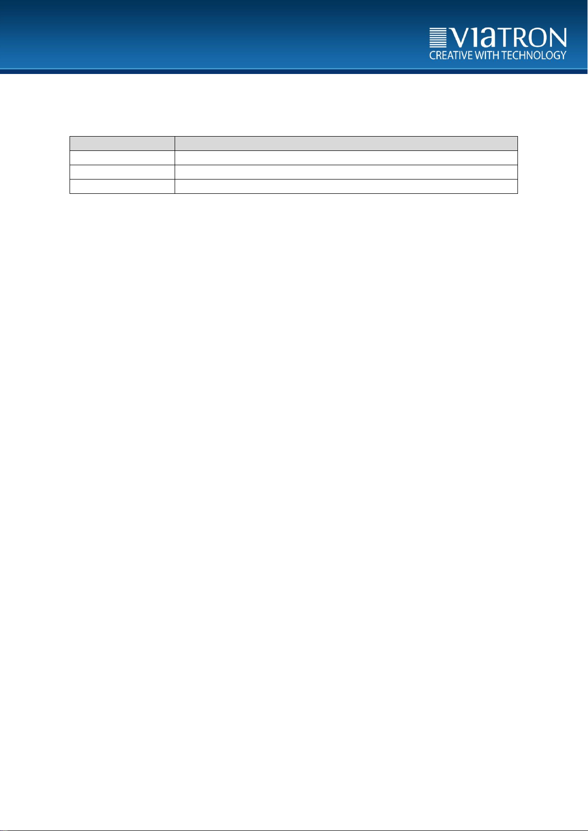
KNX IR Linker
IR-Signal
KNX-telegrams
IR-Signal
Various KNX devices
Various KNX devices
KNX- telegrams
2 Block diagram
2.1 Schema KNX IR Linker
Figure 1: Schematic KNX IR linker
Seite 6 von 22
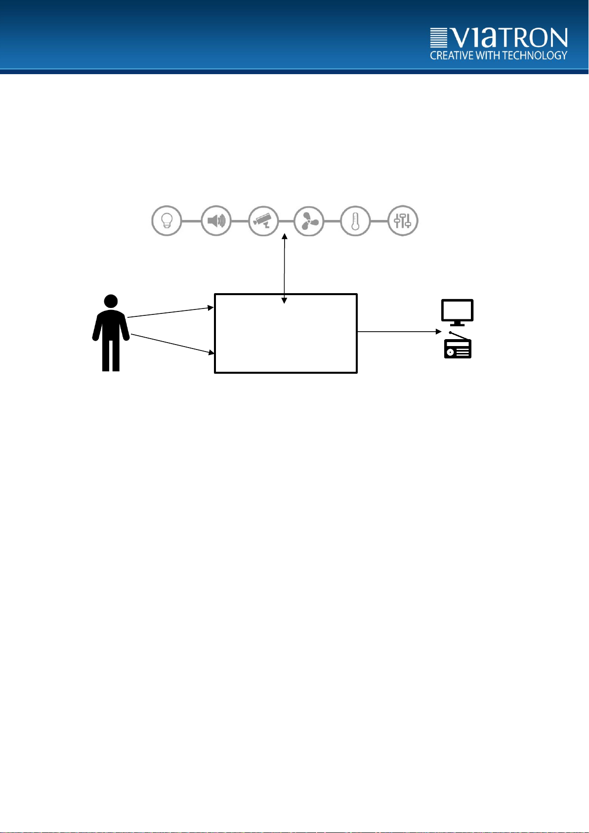
3 Connections on the unit (rear panel)
Electrical voltage!
When working on electrical systems and equipment, there is a danger to life and fire!
Work on the KNX IR linker may only be carried out by an electrician.
Figure 2: Back of the unit
3.1 KNX Port
The connection to the KNX bus system is carried out via screw terminals of type
Weidmüller BL 5.08 / 02/180 SN OR BX. The screw clamp is included in the delivery.
The power consumption of the KNX connection is indicated in the data sheet.
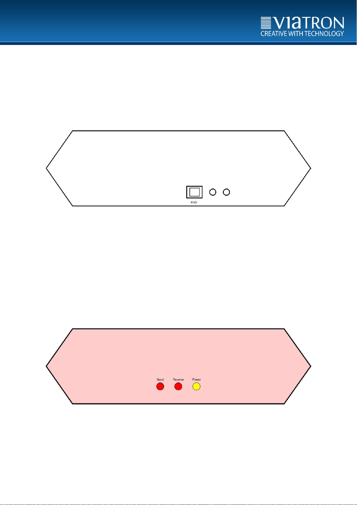
4 Display of the front panel
Figure 3: Front of the unit
LEDs display various statuses for the user. These can be taken from the scale in chapter
8.2.
Seite 7 von 22

Object
Title
Function
Data Type
1
teaching/activate KNX to IR
Scene
18.001
SceneControl
Speicherplatz
Objektnummer
Datenpunkttyp
Typ
Funktion 1 10
1.001
Schalt1
Toggle 2 12
1.001
Schalt2
Toggle 3 14
1.001
Schalt3
Toggle 4 16
1.001
Schalt4
Toggle 5 18
1.001
Schalt5
Toggle
6
20
1.001
Schalt6
Toggle 7 22
1.001
Schalt7
Toggle
8
24
1.001
Schalt8
Toggle 9 26
1.001
Schalt9
Toggle
10
28
1.001
Schalt10
Toggle
11
30
1.001
Schalt11
Toggle
12
32
1.001
Schalt12
Toggle
13
34
1.001
Schalt13
Toggle
14
36
1.001
Schalt14
Toggle
15
38
1.001
Schalt15
Toggle
16
40
1.001
Schalt16
Toggle
17
42
1.001
Schalt17
Toggle
18
44
1.001
Schalt18
Toggle
19
46
1.001
Schalt19
Toggle
20
48
1.001
Schalt20
Toggle
21
50
1.001
Schalt21
Toggle
22
52
1.001
Schalt22
Toggle
23
60
3.007
Dim1
Decrease
24
Decrease/Increase
Increase
5 KNX Object description
The KNX IR linker has various data interfaces. This means that the device can also be
apealed via various protocols. The system is normally used for connection to the KNX
building bus.
The following chapter describes the control of the KNX IR Linker via the KNX
communication objects.
5.1 Scene building Implementation IR to KNX
The communication object 1 offers a total of 64 memory locations. The KNX IR linker
links these storage locations with predefined datapoint types.
The KNX IR linker can read and store IR signals. If the KNX IR linker receives a stored IR
signal, it sends a KNX command, as shown in the following table.
This makes it possible to control the following data point types via already taught-in IR
signals:
1.001 Switch
3.007 Dimmer
1.008 Up/Down
The following scale shows which data point is assigned to which memory location.
Seite 8 von 22

25
62
3.007
Dim2
Decrease
26
Decrease/Increase
Increase
27
64
3.007
Dim3
Decrease
28
Decrease/Increase
Increase
29
66
3.007
Dim4
Decrease
30
Decrease/Increase
Increase
31
68
3.007
Dim5
Decrease/Increase
Toggle
32
70
3.007
Dim6
Decrease/Increase
Toggle
33
72
3.007
Dim7
Decrease/Increase
Toggle
34
80
1.008
Jal 1
Up
35
Move Up/Down
Down
36
82
1.008
Jal 2
Up
37
Move Up/Down
Down
38
84
1.008
Jal 3
Up
39
Move Up/Down
Down
40
86
1.008
Jal 4
Up
41
Move Up/Down
Down
42
88
1.008
Jal 5
Up
43
Move Up/Down
Down
44
90
1.008
Jal 6
Up
45
Move Up/Down
Down
46
92
1.008
Jal 7
Up
47
Move Up/Down
Down
48
49
50
51
52
53
54
55
56
57
58
59
60
61
62
63
64
The free space is reserved for future functions. The communication objects to be
controlled are explained further in sections 5.4ff.
Seite 9 von 22

Object
Title
Function
Data Ttype
2
Teaching/Activate KNX to IR
Scene
18.001
SceneControl
Object
Title
Function
Data Type
5
String Output
String
16.000 String
String
Description
IR [Number]
saved
The received IR code was assigned to the desired scene number
IR [Number] send
The IR code of the desired scene number, was sent
No IR-Code
During transmission, there is no IR code under the desired scene
number
ERR: Learn
An error occurred during the learning process
ERR: Save
An error occurred during the memory process
IR [Nummer] hold
The IR code for the scene with the number [number] has been
received
IR [Nummer]
release
The IR code for the scene with the number [number] has been
reset
IR [Nummer]
pulse
The IR code for the scene with the number [number] has been
received
No KNX Cmd
The received IR code is not stored under a scene
not available
This scene number is not available
IR not found
IR Code not found
5.2 Scene building Implementation KNX to IR
The communication object 2 has a total of 64 memory locations. These memory
locations are used by the KNX IR linker to store and transmit IR signals.
The communication object can emit a previously learned IR signal by receiving a KNX
telegram. Here, all 64 storage locations of the communication object 2 can be used.
5.3 String Output
This communication object is used for the output of strings on the building bus.
Messages about the status of the KNX IR linker are emited. The following scale shows
which strings are emited and their meaning.
.
Seite 10 von 22

Object
Scene Number
Title
Function
10
0
Schalt1
Toggle
11
Status1
Status
12
1
Schalt2
Toggle
13
Status2
Status
14
2
Schalt3
Toggle
15
Status3
Status
16
3
Schalt4
Toggle
17
Status4
Status
18
4
Schalt5
Toggle
19
Status5
Status
20
5
Schalt6
Toggle
21
Status6
Status
22
6
Schalt7
Toggle
23
Status7
Status
24
7
Schalt8
Toggle
25
Status8
Status
26
8
Schalt9
Toggle
27
Status9
Status
28
9
Schalt10
Toggle
29
Status10
Status
30
10
Schalt11
Toggle
31
Status11
Status
32
11
Schalt12
Toggle
33
Status12
Status
34
12
Schalt13
Toggle
35
Status13
Status
36
13
Schalt14
Toggle
37
Status14
Status
38
14
Schalt15
Toggle
39
Status15
Status
40
15
Schalt16
Toggle
41
Status16
Status
42
16
Schalt17
Toggle
43
Status17
Status
44
17
Schalt18
Toggle
45
Status18
Status
46
18
Schalt19
Toggle
47
Status19
Status
48
19
Schalt20
Toggle
49
Status20
Status
50
20
Schalt21
Toggle
51
Status21
Status
52
21
Schalt22
Toggle
53
Status22
Status
5.4 Switch ON/OFF
The following scale lists the linkage of the switches. The scale shows which
communication object is linked to which scene number.
Seite 11 von 22

Object
Scene Number
Title
Function
60
23
Dim1
Increase
24
Decrease
61 Switch_Dim1
Toggel
62
25
Dim2
Increase
26
Decrease
63 Switch_Dim2
Toggel
64
27
Dim3
Increase
28
Decrease
65 Switch_Dim3
Toggel
66
29
Dim4
Increase
30
Decrease
67 Switch_Dim4
Toggel
Object
Scene Number
Title
Function
68
31
Dim5
Increase/ Decrease
69 Switch_Dim5
Toggel
70
32
Dim6
Increase/ Decrease
71 Switch_Dim6
Toggel
72
33
Dim7
Increase/ Decrease
73 Switch_Dim7
Toggel
Each object description of a switch consists of one object with the function Switch and
from another object with the function Status.
5.5 Dimmer module 2 -button operation
If a stored IR signal is received at the KNX IR linker and if it is assigned to a dimmer
function, the corresponding communication object is executed. One IR signal is required
for each increase and decrease. The dimmer modules are always controlled with a
stepcode of 100%. As long as an IR signal is received, the dimming function is activated.
If no IR signal is received, the KNX IR linker automatically sends the stop command. If an
IR signal is received at short notice, the respective switch function for this dimmer is
executed (ON or OFF).
5.6 Dimmer module 1 -button operation
If a stored IR signal is received at the KNX IR linker and if it is assigned to a dimmer
function, the corresponding communication object is executed. In this case, only an IR
signal is required, which tumbles its function after each keypress. The dimmer modules
are always controlled with a stepcode of 100%. As long as an IR signal is received, the
dimming function is activated. If no IR signal is received, the KNX IR linker automatically
sends the stop command. If an IR signal is received at short notice, the respective switch
function for this dimmer is executed (toggle ON / OFF).
Seite 12 von 22

Object
Scene Number
Title
Function
80
34
Jal1
Move Up
35
Move Down
81 Lamellen1
Up
Down
82
36
Jal2
Move Up
37
Move Down
83 Lamellen2
Up
Down
84
38
Jal3
Move Up
39
Move Down
85 Lamellen3
Up
Down
86
40
Jal4
Move Up
41
Move Down
87 Lamellen4
Up
Down
88
42
Jal5
Move Up
43
Move Down
89 Lamellen5
Up
Down
90
44
Jal6
Move Up
45
Move Down
91 Lamellen6
Up
Down
92
46
Jal7
Move Up
47
Move Down
93 Lamellen7
Up
Down
5.7 Blind module 2-button operation
If a stored IR signal is received at the KNX IR linker and a blind function is assigned to it,
the corresponding communication object is executed. The following options are
available for operating the blinds:
If an IR signal is received for more than 2 seconds, the blind is lowered or raised until an
IR signal has been received again or the limit switch has been reached. If an IR signal is
less than two seconds, the blind is lowered or raised for this time. If an IR signal is only
received by pulse, the louvres of the blind are adjusted.
Seite 13 von 22

6 Teaching and sending IR signals
The KNX IR linker can only be operated via the KNX bus or by an IR signal, as shown in
the area ERROR! Reference source not found.
This section describes the following examples:
1. how an IR signal is taught into the KNX IR linker,
2. an IR signal can be transmitted via a KNX command and
3. how a KNX object is triggered by a learned IR signal.
It is assumed that the KNX IR linker is set up as described in chapter 7 and is functional.
6.1 Teaching and storing an IR signal
This procedure applies to both scene modules IR to KNX and KNX to IR.
Figure 4: Scheme for the teach-in of an IR signal
1. The user sends the KNX command to activate the teach-in process via the KNX bus.
For this purpose, the scene building block (communication object 1 or 2) is addressed
with the corresponding storage location number. The operating mode is "learn".
2. As soon as the KNX IR linker has received the command, the Receive LED is lit. Thus,
the KNX IR linker signals that it is in the learn state and waits for an IR signal for 30
seconds.
3. Within 30 seconds the user sends an IR signal which he wants to store on the desired
scene to the KNX IR linker. If a valid IR signal is not received within 30 seconds, the
Receive LED goes out and the KNX IR Linker returns to normal operating mode.
4. The received IR Signal is stored by the KNX IR linker and the Receive LED flashes for a
short time.
5. The Receive LED goes out and the KNX IR Linker is back in normal operating mode.
Seite 14 von 22

6.2 IR signal triggers KNX command:
This is only possible with the scene module IR to KNX.
If a stored IR signal is detected, the Receive LED flashes and the KNX IR linker sends out
the stored KNX command for the corresponding scene.
6.3 KNX command initiates transmission of an IR Signal:
This is only possible with the scene module KNX to IR.
Figure 5: Scheme KNX command for sending an IR signal
1. The user sends the KNX command to activate the transmission process via the KNX
bus.
2. If a stored IR signal is found for this command, the Send LED flashes and the KNX IR
linker transmits the stored IR code of the corresponding scene.
Seite 15 von 22

7 Installation of the device
Please note that the KNX IR linker is placed within range, of the IR devices to be
controlled. In this case, disturbing influences, such as, for example, sun
radiation, have to be noticed and minimized.
The KNX IR Linker requires a KNX bus connection for the supply.
Programming key and LED as well as interfaces are only accessible from the rear panel.
If possible, load physical address and application software into the device before setting
it up.
Seite 16 von 22

Technical specifications
KNX IR Linker
power supply
KNX- bus voltage
ambient temperature
0 C° bis 45 C°
current consumption KNX Bus
max. 10mA
IR transmission range
up to 7m (Free view
frontal/ standard receiver)
protection
IP30 according to DIN EN 60529
weight
0,5Kg
dimensions (L/W/H)
119,5/89/50
attachment
free installation
8 Technical Specifications
8.1 Data sheet
Seite 17 von 22

8.2 System and error messages (front LEDs)
The KNX IR linker has LEDs on the front panel that are grouped as follows:
Status LEDs:
1x Power
1x Receive
1x Send
The function of the LEDs is shown in the following section.
Power LED is on:
Operating voltage is applied, KNX IR Linker ready for operation.
Receive LED is lit:
The KNX IR linker is in the learn state and waits for an IR signal to save it.
Receive LED changes from continuous to flashing:
During the learn process, a valid IR signal was received and stored.
Receive LED flashes:
The KNX IR linker has received an IR signal, which has been learned in advance.
Send LED flashes:
The KNX IR linker emits an IR signal.
Seite 18 von 22

9 Maintenance and Care
Never use caustic agents or solvents for cleaning. The device can be cleaned with a dry
cloth from the outside.
Otherwise, the device is maintenance-free. No repairs may be carried out in case of
damage (for example, by transport or storage).
Seite 19 von 22

10 Important information
10.1 Disclaimer
Despite the examination of the contents of this print-out for conformity with the
hardware and software deviations are not always completely excluded. Therefor we are
unable to offer any legal guarantee for its correctness. Necessary corrections are taken
into account in new versions of the manual.
We reserve the right to make technical changes to the products as well as changes to the
content of this document at any time without prior notice.
Installation and assembly of electrical devices may only be carried out by a qualified
electrician. It is essential to observe the applicable accident prevention regulations.
Failure to observe the installation instructions may result in damage to the unit itself,
fire or other hazards.
This manual is part of the product and must remain with the end customer.
10.2 Intended use
The KNX IR Linker is designed for indoor installation
10.3 Warranty
We provide warranty within the scope of the legal provisions.
Please send the device with a fault description and in the original packaging to our
service center (Viatron GmbH, Carl-Metz-Str. 3, 76275 Ettlingen)
Seite 20 von 22

Protocol
Manufacturer
A1TVBOX
ADB (Advanced Digital Broadcast), z.B. A1 TV Box
APPLE
Apple
ACP24
Stiebel Eltron
B&O
Bang & Olufsen
BOSE
Bose
DENON
Denon, Sharp
FAN
FAN, Fernsteuerung für Ventilatoren
FDC
FDC Keyboard
GRUNDIG
Grundig
NOKIA
Nokia, z.B. D-Box
IR60
(SDA2008)
Diverse europäische Hersteller
JVC
JVC
KASEIKYO
Panasonic, Technics, Denon und andere japanische Hersteller, welche Mitglied der
"Japan's Association for Electric Home Application" sind.
KATHREIN
KATHREIN
LEGO
Lego
LGAIR
LG Air Conditioner
MATSUSHITA
Matsushita
NEC16
JVC, Daewoo
NEC42
JVC
MERLIN
MERLIN Fernbedienung (Pollin Bestellnummer: 620 185)
NEC
NEC, Yamaha, Canon, Tevion, Harman/Kardon, Hitachi, JVC, Pioneer, Toshiba, Xoro, Orion,
NoName und viele weitere japanische Hersteller.
NETBOX
Netbox
NIKON
NIKON
NUBERT
Nubert, z.B. Subwoofer System
ORTEK
Ortek, Hama
PANASONIC
PANASONIC Beamer
PENTAX
PENTAX (NEU!)
RC5
Philips und andere europäische Hersteller
RC6A
Philips, Kathrein und andere Hersteller, z.B. XBOX
RC6
Philips und andere europäische Hersteller
RCCAR
RC Car: IR Fernbedienung für Modellfahrzeuge
RECS80
Philips, Nokia, Thomson, Nordmende, Telefunken, Saba
RECS80EXT
Philips, Technisat, Thomson, Nordmende, Telefunken, Saba
RCMM
Fujitsu-Siemens z.B. Activy keyboard
ROOMBA
iRobot Roomba Staubsauger
S100
Ähnlich zu RC5, aber 14 statt 13 Bits und 56kHz Modulation. Hersteller unbekannt.
SAMSUNG32
Samsung
SAMSUNG48
Div. Klimaanlagen Hersteller
SAMSUNG
Samsung
RUWIDO
RUWIDO (z.B. T-Home-Mediareceiver, MERLIN-Tastatur (Pollin))
SIEMENS
Siemens, z.B. Gigaset M740AV
SIRCS
Sony
SPEAKER
Lautsprecher Systeme wie z.B. X-Tensions
TECHNICS
Technics
TELEFUNKEN
Telefunken
THOMSON
Thomson
10.4 Supported IR protocols
Seite 21 von 22

11 Contact
Viatron GmbH
Carl-Metz-Str. 3
76275 Ettlingen
Tel.: +49 7243 5148 370
Fax: +49 7243 5148 351
Email: info@viatron.de
For more information:
www.viatron.de
Seite 22 von 22
 Loading...