

Page 1

Page 1 of 23
Viatron GmbH - KNX
MultiRoom Audio - Autrix
Technical Manual
Page 2

Page 2 of 23
Contents Page
1 General description: ................................................................................................................. 4
2 Block diagramm ........................................................................................................................ 5
2.1 Schema Autrix with 4 zones ............................................................................................................... 5
2.2 Schema Autrix with 8 zones ............................................................................................................... 5
3 Connections to he unit (rear side oft he unit) ......................................................................... 6
3.1 Loudspeaker connections .................................................................................................................. 6
3.2 Audio Output (NF) ................................................................................................................................ 6
3.3 Audio Input (NF) ................................................................................................................................... 6
3.4 RS232 Port ............................................................................................................................................ 6
3.5 KNX Port ............................................................................................................................................... 7
3.6 Option ................................................................................................................................................... 7
3.7 Power Supply ....................................................................................................................................... 7
4 KNX Object description / general functions ............................................................................ 7
4.1 General describtion ............................................................................................................................. 7
4.2 Switching the Amplifier board ON/OFF ............................................................................................. 7
4.3 Amplifier - board temperature ............................................................................................................ 7
4.4 Master mute ON / OFF ......................................................................................................................... 8
4.5 Alarm - overheating ............................................................................................................................. 8
5 KNX Object description / Amplifier .......................................................................................... 8
5.1 Anplifier n: Input signal - stepwise .................................................................................................... 8
5.2 Amplifier n: Input signal - value ......................................................................................................... 9
5.3 Amplifier n: Input signal - status ........................................................................................................ 9
5.4 Amplifier n: Mute ON / OFF ............................................................................................................... 10
5.5 Amplifier n: Volumne - status ........................................................................................................... 10
6 KNX Object description / Sound settings ............................................................................. 11
6.1 Amplifier n: Treble, setting - steppwise .......................................................................................... 11
6.2 Amplifier n: Treble, setting - value ................................................................................................... 11
6.3 Amplifier n: Treble - status ............................................................................................................... 12
6.4 Amplifier n: Middle, setting - steppwise .......................................................................................... 12
6.5 Amplifier n: Middle, setting - value .................................................................................................. 13
6.6 Amplifier n: Middle - status............................................................................................................... 13
6.7 Amplifier n: Bass, setting - steppwise ............................................................................................. 14
6.8 Amplifier n: Bass, setting - value ..................................................................................................... 14
6.9 Amplifier n: Bass - status ................................................................................................................. 15
7 KNX object description / Input gain ....................................................................................... 15
7.1 Explanation ........................................................................................................................................ 15
7.2 Audio input n: Setting the input gain - steppwise .......................................................................... 15
7.3 Audio input n: Setting the input gain - value .................................................................................. 16
7.4 Audio input n: Input gain - status .................................................................................................... 16
8 KNX object description / Setting (save/reset) ....................................................................... 16
8.1 Explanation ........................................................................................................................................ 16
8.2 Sound settings: Save ........................................................................................................................ 17
8.3 Sound Settings: Reset ...................................................................................................................... 17
9 Operating via frontpanel......................................................................................................... 17
9.1 Power / ON - OFF ............................................................................................................................... 17
9.2 Setting an input source for a zone ................................................................................................... 18
9.3 Setting the volumne for a zone ........................................................................................................ 18
9.4 Setting the tone control for a zone (bass control) ......................................................................... 18
9.5 Setting the tone control for a zone (treble control) ........................................................................ 18
9.6 MasterMute / ON - OFF ...................................................................................................................... 19
10 Installing and connecting the device..................................................................................... 19
Page 3

Page 3 of 23
11 Technical Data ........................................................................................................................ 20
11.1 Data sheet ........................................................................................................................................... 20
11.2 System and error messages (LEDs Front) ...................................................................................... 21
12 Maintenance and care ............................................................................................................ 22
13 Important Information ............................................................................................................. 22
13.1 Liability exclusion .............................................................................................................................. 22
13.2 Approved use ..................................................................................................................................... 22
13.3 Warranty ............................................................................................................................................. 22
13.4 Warning notices ................................................................................................................................. 22
14 Contact .................................................................................................................................... 23
Page 4

Page 4 of 23
1 General description:
The Autrix is an Audiomatrix with integrated amplifier stages. With the Autrix music can be distributed into
varies areas. Scope of application is from private homes to office buildings.
Basically due to the modulare structure, there is the possibility of various expansion options.
The basic version is available with the following technical features:
Input: 4 stereo audio input (NF signals)
Output: up to 8 speaker output (8 Ohm)
2 stereo audio output (NF signals)
The AUTRIX is directly connected to the KNX building bus. So the controlling can be made by the installed
switch range/visualisation.
The device can also be controlled directly over the front panell located on front of the device.
Page 5
Page 5 of 23
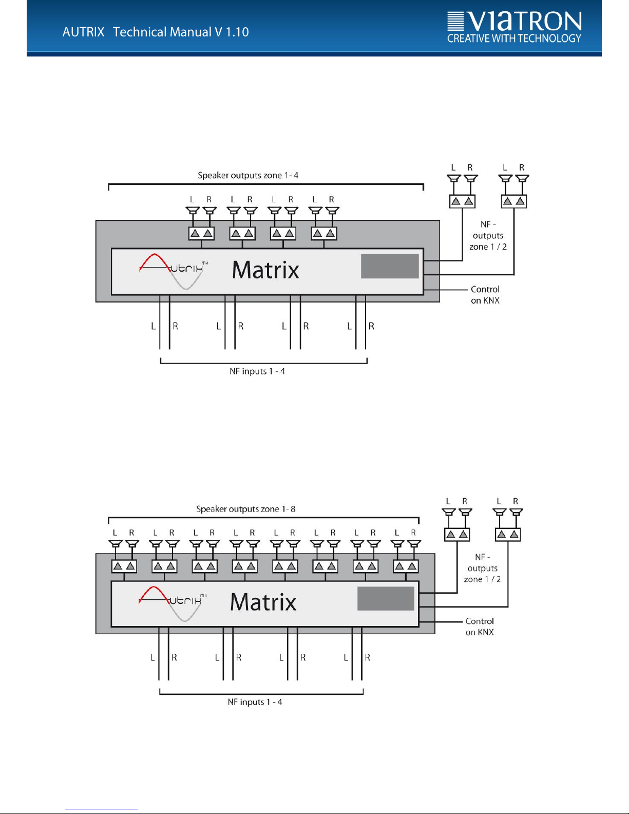
2 Block diagramm
2.1 Schema Autrix with 4 zones
Figure: Schema Autrix with 4 amplifier zones
2.2 Schema Autrix with 8 zones
Figure: Schema Autrix with 8 amplifier zones
Page 6
Page 6 of 23
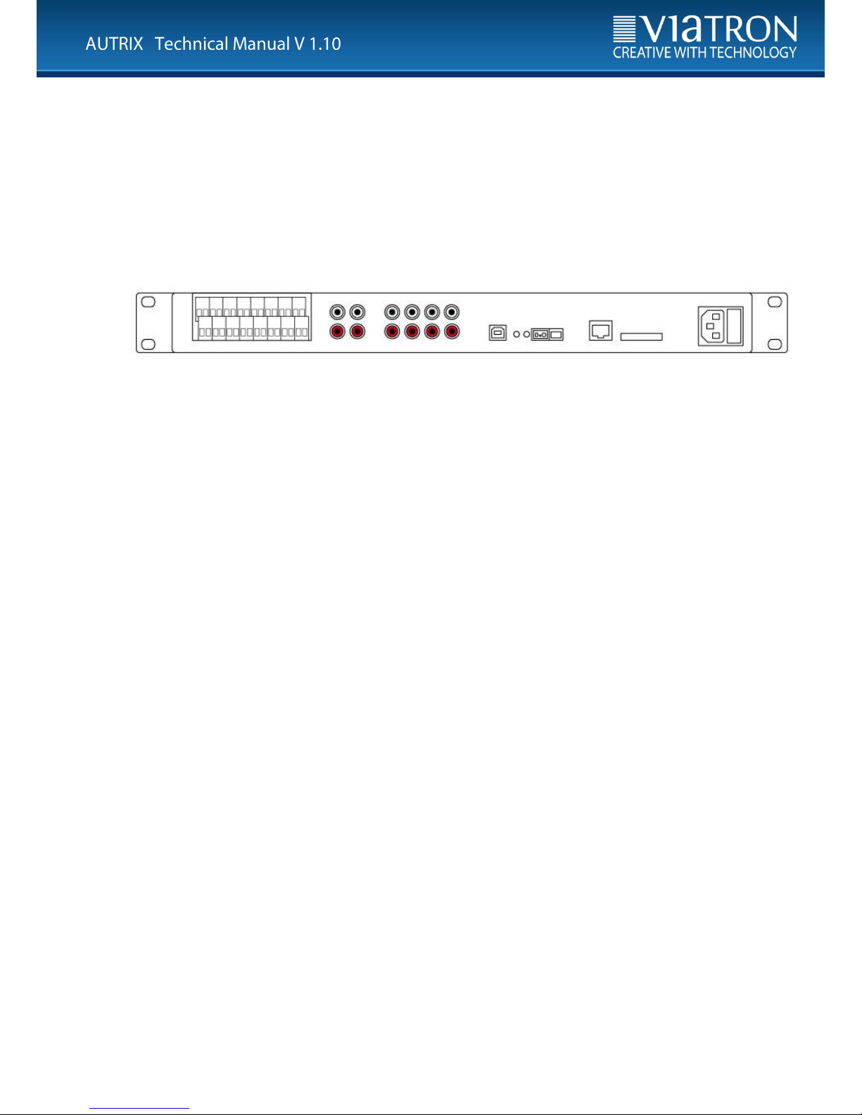
3 Connections to he unit (rear side oft he unit)
Electrical voltage !
Working on electrical systems or devices could be a danger to life due to possible hazard of
electric shock or fire hazard!
Work on the 230 V network may only be carried out by skilled electricians!
Figure: rear side of unit
Speaker Audio OUT Audio IN RS232 KNX Option Net
3.1 Loudspeaker connections
Only speakers with the following features can be connected to the AUTRIX:
Capacity: min. 30 W
Impedance: 8 Ohm
The speaker cabling is connected to the Autrix via srew terminals. These srew terminals allow the connection
of cabels up to 2,5 qmm.
3.2 Audio Output (NF)
In addition to the amplifier outputs the Autrix also sends unreinforced audio signals. These signals can be
connected to external amplifier.There are two of those audio outputs available:
Audio signal of zone 1 (stereo)
Audio signal of zone 2 (stereo)
These NF-signals are logically connected to the same KNX communication objects, as the amplifier output.
3.3 Audio Input (NF)
Up to 4 onsite audio devices, are connected to the 4 audio NF inputs (stereo RCA sockets) of the Autrix.
These audio input signals are then available for all integrated amplifier stages (up to 8 amplifier).
3.4 RS232 Port
Not available in current version.
Page 7
Page 7 of 23
3.5 KNX Port
The connection to the KNX bussystem occurs by screw terminal type Hartmann/PTR BU9502, which is
included in the scope of delivery.
The power consumption of the KNX connection is listed in the data sheet.
3.6 Option
The ports are not occupied and irrelevant for the operation at the KNX system.
3.7 Power Supply
The power supply is send to the Autrix via a power cord (IEC60320-C13), which is included in the scope of
delivery.
4 KNX Object description / general functions
4.1 General describtion
The Autrix comes with several data interfaces. Which means that the device can be activated over several
protocols. Normaly the device is destined for the connection to the KNX builduíng bus. This section
describes the controlling of the Autrix over the KNX communication objects..
4.2 Switching the Amplifier board ON/OFF
Object
Designation
Function
Data type
1
Amplifier board ON/OFF
switch
1.001 ON/OFF
2
Amplifier board ON/OFF
status
1.001 ON/OFF
Via the communication object 1 the amplifier board can be switched ON or OFF. Object 2 sends back the
status. Even after switching off the amplifier boards the Autrix can still receive or send telegrams.
Switching off the amplifier board is recommended, if the autrix will not be in use for a longer period of time
(for example: nighttime, vaccation etc.).
4.3 Amplifier - board temperature
Object
Designation
Function
Data type
3
Amplifier board temperature
status
9.001 temperature
The object sends the temperature of the amplifier board as a status to the KNX bus. The correspondent
telegram will always be send, if the temperature has changed by minimum 1 degree.
Page 8

Page 8 of 23
4.4 Master mute ON / OFF
Object
Designation
Function
Data type
4
Master mute ON/OFF
switch
1.001 ON/OFF
5
Master mute ON/OFF
status
1.001 ON/OFF
Via the communication object 4 the master mute can be switched ON or OFF. Object 5 sends back the
status. If master mute (value 1) is set, all amplifiers are on silent.
The value 0 sets the amplifier back to the state before the muting.
Switching off the amplifiers via the master mute is recommended, when all amplifier outputs need to be set
to silent momentary (for example incomming phonecall, announcement etc.).
4.5 Alarm - overheating
Object
Designation
Function
Data type
8
Alarm overheating
status
1.002 Boolesch
In case of overheating of the system this object will be sent with value 1.
At the end of the alarm (temperature back to normal) the status will send the value 0.
During the period of the alarm the Autrix M4 is switched off automatically. Afterwards the Autrix M4 needs to
be turned on again (through KNX Bus or trough the front panel oft he device).
5 KNX Object description / Amplifier
5.1 Anplifier n: Input signal - stepwise
Object
Designation
Function
Data type
31
Amplifier 1 Input-signal
stepwise
step
1.007 step
51
Amplifier 2 Input-signal
stepwise
step
1.007 step
71
Amplifier 3 Input-signal
stepwise
step
1.007 step
91
Amplifier 4 Input-signal
stepwise
step
1.007 step
111
Amplifier 5 Input-signal
stepwise
step
1.007 step
131
Amplifier 6 Input-signal
stepwise
step
1.007 step
151
Amplifier 7 Input-signal
stepwise
step
1.007 step
171
Amplifier 8 Input-signal
stepwise
step
1.007 step
The input signals for the amplifiers (audio zones) are selected via these communication objects. There are 4
input signals available. By sending the value 1 to a communication object, it will be switched to the next
higher input number. Equivalent the value 0 switches to the next lower input number.
Page 9

Page 9 of 23
5.2 Amplifier n: Input signal - value
Object
Designation
Function
Data type
32
Amplifier 1 Input signal-
value
value
5.010 counting impulse
52
Amplifier 2 Input signal-
value
value
5.010 counting impulse
72
Amplifier 3 Input signal-
value
value
5.010 counting impulse
92
Amplifier 4 Input signal-
value
value
5.010 counting impulse
112
Amplifier 5 Input signal-
value
value
5.010 counting impulse
132
Amplifier 6 Input signal-
value
value
5.010 counting impulse
152
Amplifier 7 Input signal-
value
value
5.010 counting impulse
172
Amplifier 8 Input signal-
value
value
5.010 counting impulse
The input signals for the amplifiers (audio zones) are selected via these communication objects.
There are 4 input signals available. Sending…….
….value 1 connects the amplifier n with the audio input 1.
….value 2 connects the amplifier n with the audio input 2.
….value 3 connects the amplifier n with the audio input 3.
….value 4 connects the amplifier n with the audio input 4.
Value 0 would clear the routing.
5.3 Amplifier n: Input signal - status
Object
Designation
Function
Data type
33
Amplifier 1 Input signal-
status
status
5.010 counting impulse
53
Amplifier 2 Input signal-
status
status
5.010 counting impulse
73
Amplifier 3 Input signal-
status
status
5.010 counting impulse
93
Amplifier 4 Input signal-
status
status
5.010 counting impulse
113
Amplifier 5 Input signal-
status
status
5.010 counting impulse
133
Amplifier 6 Input signal-
status
status
5.010 counting impulse
153
Amplifier 7 Input signal-
status
status
5.010 counting impulse
173
Amplifier 8 Input signal-
status
status
5.010 counting impulse
Via these communication objects the Autrix M4 sends back the number of the audio input, which was
currently selected.
Page 10

Page 10 of 23
5.4 Amplifier n: Mute ON / OFF
Objekt
Designation
Function
Data type
34
Amplifier 1 Mute ON/OFF
switch
1.001 ON/OFF
35
Amplifier 1 Mute ON/OFF
status
1.001 ON/OFF
54
Amplifier 2 Mute ON/OFF
switch
1.001 ON/OFF
55
Amplifier 2 Mute ON/OFF
status
1.001 ON/OFF
74
Amplifier 3 Mute ON/OFF
switch
1.001 ON/OFF
75
Amplifier 3 Mute ON/OFF
status
1.001 ON/OFF
94
Amplifier 4 Mute ON/OFF
switch
1.001 ON/OFF
95
Amplifier 4 Mute ON/OFF
status
1.001 ON/OFF
114
Amplifier 5 Mute ON/OFF
switch
1.001 ON/OFF
115
Amplifier 5 Mute ON/OFF
status
1.001 ON/OFF
134
Amplifier 6 Mute ON/OFF
switch
1.001 ON/OFF
135
Amplifier 6 Mute ON/OFF
status
1.001 ON/OFF
154
Amplifier 7 Mute ON/OFF
switch
1.001 ON/OFF
155
Amplifier 7 Mute ON/OFF
status
1.001 ON/OFF
174
Amplifier 8 Mute ON/OFF
switch
1.001 ON/OFF
175
Amplifier 8 Mute ON/OFF
status
1.001 ON/OFF
Via these communication objects the amplifier mute can be switched ON or OFF. If the amplifier mute (value
1) is set, the equivalent amplifier is set on silent. Value 0 sets the amplifier back to the state before the
muting.
The master mute (see previous chapter) is always higher ranking than the amplifier (zone) mute. If master
mute is set, all zones (amplifiers) are muted. But the master mute does not overwrite the communication
object of the muting of the individual amplifiers. So if the master mute is set to vealue 0, again this data point
is relevant to mute or unmute the individual zone.
5.5 Amplifier n: Volumne - status
Objekt
Designation
Function
Data type
33
Amplifier 1 Volume
status
status
5.001 percent (0-100)
53
Amplifier 2 Volume
status
status
5.001 percent (0-100)
73
Amplifier 3 Volume
status
status
5.001 percent (0-100)
93
Amplifier 4 Volume
status
status
5.001 percent (0-100)
113
Amplifier 5 Volume
status
status
5.001 percent (0-100)
133
Amplifier 6 Volume
status
status
5.001 percent (0-100)
153
Amplifier 7 Volume
status
status
5.001 percent (0-100)
173
Amplifier 8 Volume
status
status
5.001 percent (0-100)
Via these communication objects the Autrix sends back the currently volume level of an amplifier.
Page 11

Page 11 of 23
6 KNX Object description / Sound settings
6.1 Amplifier n: Treble, setting - steppwise
Object
Designation
Function
Data type
39
Amplifier 1 Treble
stepped
step
1.007 step
59
Amplifier 2 Treble
stepped
step
1.007 step
79
Amplifier 3 Treble
stepped
step
1.007 step
99
Amplifier 4 Treble
stepped
step
1.007 step
119
Amplifier 5 Treble
stepped
step
1.007 step
139
Amplifier 6 Treble
stepped
step
1.007 step
159
Amplifier 7 Treble
stepped
step
1.007 step
179
Amplifier 8 Treble
stepped
step
1.007 step
The amplifier treble setting can be controlled via these communication objects.
The data point is intended for steppwise modification of the trebles. When the value 1 is sent to a
communication object, the system switches to the next highest value. Accordingly, the value 0 switches to
the next lowest value.
6.2 Amplifier n: Treble, setting - value
Object
Designation
Function
Data type
40
Amplifier 1 Treble
values
value
5.001 percent (0-100)
60
Amplifier 2 Treble
values
value
5.001 percent (0-100)
80
Amplifier 3 Treble
values
value
5.001 percent (0-100)
100
Amplifier 4 Treble
values
value
5.001 percent (0-100)
120
Amplifier 5 Treble
values
value
5,001 percent (0-100)
140
Amplifier 6 Treble
values
value
5,001 percent (0-100)
160
Amplifier 7 Treble
values
value
5,001 percent (0-100)
180
Amplifier 8 Treble
values
value
5,001 percent (0-100)
The amplifier treble setting can be controlled via these communication objects. Using the data point, an
amplifier can be set directly to a specific value.
Page 12

Page 12 of 23
6.3 Amplifier n: Treble - status
Object
Designation
Function
Data type
41
Amplifier 1 Treble
status
status
5.001 percent (0-100)
61
Amplifier 2 Treble
status
status
5.001 percent (0-100)
81
Amplifier 3 Treble
status
status
5.001 percent (0-100)
101
Amplifier 4 Treble
status
status
5.001 percent (0-100)
121
Amplifier 5 Treble
status
status
5.001 percent (0-100)
141
Amplifier 6 Treble
status
status
5.001 percent (0-100)
161
Amplifier 7 Treble
status
status
5.001 percent (0-100)
181
Amplifier 8 Treble
status
status
5.001 percent (0-100)
The Autrix sends the treble setting status value back to the appropriate zone using these communication
objects.
6.4 Amplifier n: Middle, setting - steppwise
Object
Designation
Funktion
Datentyp
42
Amplifier 1 Middle
steppwise
step
1.007 step
62
Amplifier 2 Middle
steppwise
step
1.007 step
82
Amplifier 3 Middle
steppwise
step
1.007 step
102
Amplifier 4 Middle
steppwise
step
1.007 step
122
Amplifier 5 Middle
stepped
step
1.007 step
142
Amplifier 6 Middle
steppwise
step
1.007 step
162
Amplifier 7 Middle
steppwise
step
1.007 step
182
Amplifier 8 Middle
steppwise
step
1.007 step
The middle setting can be controlled via these communication objects. The data point is intended for
steppwise modification of the middles. When the value 1 is sent to a communication object, the system
switches to the next highest value. Accordingly, the value 0 switches to the next lowest value.
Page 13

Page 13 of 23
6.5 Amplifier n: Middle, setting - value
Object
Designation
Function
Data type
43
Amplifier 1 Middle
value
value
5.001 percent (0-100)
63
Amplifier 2 Middle
value
value
5.001 percent (0-100)
83
Amplifier 3 Middle
value
value
5.001 percent (0-100)
103
Amplifier 4 Middle
value
value
5.001 percent (0-100)
123
Amplifier 5 Middle
value
value
5.001 percent (0-100)
143
Amplifier 6 Middle
value
value
5.001 percent (0-100)
163
Amplifier 7 Middle
value
value
5.001 percent (0-100)
183
Amplifier 8 Middle
value
value
5.001 percent (0-100)
The middle setting can be controlled via these communication objects. Using the data point, an amplifier can
be set directly to a specific value.
6.6 Amplifier n: Middle - status
Object
Designation
Function
Data type
44
Amplifier 1 Middle
status
status
5.001 percent (0-100)
64
Amplifier 2 Middle
status
status
5.001 percent (0-100)
84
Amplifier 3 Middle
status
status
5.001 percent (0-100)
104
Amplifier 4 Middle
status
status
5.001 percent (0-100)
124
Amplifier 5 Middle
status
status
5.001 percent (0-100)
144
Amplifier 6 Middle
status
status
5.001 percent (0-100)
164
Amplifier 7 Middle
status
status
5.001 percent (0-100)
184
Amplifier 8 Middle
status
status
5.001 percent (0-100)
The Autrix sends the middle setting status value back to the appropriate zone using these communication
objects.
Page 14

Page 14 of 23
6.7 Amplifier n: Bass, setting - steppwise
Object
Designation
Function
Data type
45
Amplifier 1 Bass
steppwise
step
1.007 step
65
Amplifier 2 Bass
steppwise
step
1.007 step
85
Amplifier 3 Bass
steppwise
step
1.007 step
105
Amplifier 4 Bass
steppwise
step
1.007 step
125
Amplifier 5 Bass
steppwise
step
1.007 step
145
Amplifier 6 Bass
steppwise
step
1.007 step
165
Amplifier 7 Bass
steppwise
step
1.007 step
185
Amplifier 8 Bass
steppwise
step
1.007 step
The bass setting can be controlled via these communication objects. The data point is intended for
steppwise modification of the basses. When the value 1 is sent to a communication object, the system
switches to the next highest value. Accordingly, the value 0 switches to the next lowest value.
6.8 Amplifier n: Bass, setting - value
Object
Designation
Function
Data Type
46
Amplifier 1 Bass
value
value
5.001 percent (0-100)
66
Amplifier 2 Bass
value
value
5.001 percent (0-100)
86
Amplifier 3 Bass
value
value
5.001 percent (0-100)
106
Amplifier 4 Bass
value
value
5.001 percent (0-100)
126
Amplifier 5 Bass
value
value
5.001 percent (0-100)
146
Amplifier 6 Bass
value
value
5.001 percent (0-100)
166
Amplifier 7 Bass
value
value
5.001 percent (0-100)
186
Amplifier 8 Bass
value
value
5.001 percent (0-100)
The bass setting can be controlled via these communication objects. Using the data point, an amplifier can
be set directly to a specific value.
Page 15

Page 15 of 23
6.9 Amplifier n: Bass - status
Object
Designation
Function
Data type
47
Amplifier 1 Bass
status
status
5.001 percent (0-100)
67
Amplifier 2 Bass
status
status
5.001 percent (0-100))
87
Amplifier 3 Bass
status
status
5.001 percent (0-100)
107
Amplifier 4 Bass
status
status
5.001 percent (0-100)
127
Amplifier 5 Bass
status
status
5.001 percent (0-100)
147
Amplifier 6 Bass
status
status
5.001 percent (0-100)
167
Amplifier 7 Bass
status
status
5.001 percent (0-100)
187
Amplifier 8 Bass
status
status
5.001 percent (0-100)
The Autrix sends the bass setting status value back to the appropriate zone using these communication
objects.
7 KNX object description / Input gain
7.1 Explanation
Any number of audio sources can be connected to the 4 audio inputs of the Autrix. Such audio sources must
hand over their signal as an analogue LF signal (normally via cinch socket).
As various audio sources may supply output levels of different strengths, appropriate compensation can take
place on the Autrix. For this, the 4 inputs on the Autrix can be set independently of one another. This setting
is termed input amplification. In the as-delivered state, a medium input gain is assigned to all the inputs. This
presetting can be changed as necessary using the following communication objects. The settings described
in this chapter are intended for first start-up. Normally, the input sensitivity of an input need not be changed
in later system operation.
Please note that a high input amplification can lead to distortion of the music signal!
7.2 Audio input n: Setting the input gain - steppwise
Object
Designation
Function
Data type
191
Input 1 Input gain
steppwise
step
1.007 step
194
Input 2 Input gain
steppwise
step
1.007 step
197
Input 3 Input gain
steppwise
step
1.007 step
200
Input 4 Input gain
steppwise
step
1.007 step
The input gain of the appropriate audio input can be controlled via these communication objects. The data
point is intended for steppwise modification of the input amplification. When the value 1 is sent to a
communication object, the system switches to the next highest value. Accordingly, the value 0 switches to
the next lowest value.
Page 16

Page 16 of 23
7.3 Audio input n: Setting the input gain - value
Object
Designation
Function
Data type
192
Input 1 input gain
value
value
5.001 percent (0-100)
195
Input 2 input gain
value
value
5.001 percent (0-100)
198
Input 3 input gain
value
value
5.001 percent (0-100)
201
Input 4 input gain
value
value
5.001 percent (0-100)
The input gain of the appropriate audio input can be controlled via these communication objects. Using the
data point, the input can be set directly to a specific input gain.
7.4 Audio input n: Input gain - status
Object
Designation
Function
Data type
193
Input 1 Input gain
status
status
5.001 percent (0-100)
196
Input 2 Input gain
status
status
5.001 percent (0-100)
199
Input 3 Input gain
status
status
5.001 percent (0-100)
202
Input 4 Input gain
status
status
5.001 percent (0-100)
The Autrix sends the status value of the input gain of the appropriate audio input back via these
communication objects.
8 KNX object description / Setting (save/reset)
8.1 Explanation
In the as-delivered state, the Autrix is already assigned with a default sound setting. These settings are
suitable for most requirements.
If necessary, the sound settings can be adapted to construction-side conditions using the named KNX
communication objects.
Such adaptations can be saved permanently in the Autrix via an additional data point. This ensures that,
after voltage returns, the Autrix works with the adapted sound settings.
The data point "Reset" allows restoration of the factory sound settings.
In order to save these permanently to the Autrix, the above-mentioned data point can be used to save sound
settings.
During the saving operation (approx. 5 seconds), the Autrix does not react to bus telegrams.
Page 17

Page 17 of 23
8.2 Sound settings: Save
Object
Designation
Function
Data type
10
Save sound settings
trigger
trigger
1.017 (0-1)
The sound settings can be saved permanently using these communication objects.
8.3 Sound Settings: Reset
Object
Designation
Function
Data type
11
Sound settings reset
trigger
trigger
1.017 (0-1)
The default sound settings can be recalled using these communication objects.
9 Operating via frontpanel
The Autrix also can be controlled via the frontpanel keyboard, independently of the KNX building bus.
The following functions are available:
- switching the amplifier board On/Off
- volume setting
- routing (assigning an input source to an amplifier zone)
- adjust bass settings
- adjust trebel settings
- master mute ON/OFF
figure: frontpanel
9.1 Power / ON - OFF
Via this button the Autrix can be switched on or off. The green „power“ LED shows the current state.
In off state the Power-LED is also off. The Autrix is than in a stand-by-mode and can be turned on again at
any time. During the stand-by-mode the Autrix can also be turned on again by the KNX-interface.
Page 18

Page 18 of 23
9.2 Setting an input source for a zone
To allocate a certain input signal to a zone, the following operating steps must be accomplished:
1) selecting the input signal:
for this purpose the „IN“ key has to be pushed/confirmed until the LED line „IN“ shows the required
input-number.
2) selecting the target zone:
for this purpose the „OUT“ key has to be pushed/confirmed until the LED line „OUT“ shows the
required zone number.
3) confirming the selection (input signal/target zone):
for this purpose the „ROUTING“ key has to be pressed. This key works after the toggle principle:
pressing the key several times changes the status between:
- tieding the preselectet output / input
- untieding the preselectet output / input
9.3 Setting the volumne for a zone
To set the volume for a zone, the following operating steps must be accomplished:
1) Selecting the target zone:
for this purpose the „OUT“ key needs to be pressed until the LED line „Out“ shows the required zone
number.
2) Setting the volume:
for this purpose the keys „VOLUME+“ and „VOLUME-„ need to be pressed. Accordingly to which key
is being used, the volume changes in the before selected zone. The currently set value will be shown
in the LED line „IN“.
9.4 Setting the tone control for a zone (bass control)
To adjust the bass for a zone, the following operation steps must be accomplished:
1) Selecting the target zone:
for this purpose the „OUT“ key needs to be pressed until the LED line „Out“ shows the required zone
number.
2) Adjusting the bass:
for this purpose the keys „BASS+“ and „BASS-„ need to be pressed. Accordingly to which key is
being used, the volume changes in the before selected zone. The currently set value will be shown
in the LED line „IN“.
9.5 Setting the tone control for a zone (treble control)
To adjust the trebels for a zone, the following operation steps must be accomplished:
1) Selecting the target zone:
for this purpose the „OUT“ key needs to be pressed until the LED line „Out“ shows the required zone
number.
2) Adjusting the trebels:
for this purpose the keys „TREBLE+“ and „TREBLE-„ need to be pressed. Accordingly to which key
is being used, the treble changes in the before selected zone. The currently set value will be shown
in the LED line „IN“.
Page 19

Page 19 of 23
9.6 MasterMute / ON - OFF
The use of the function MasterMuste sets the Autrix to complete silence.
Over the „MUTE“ key, it can be turned on or off.
This key works after the Toggle principle:
pressing the key several times changes at a time the status between:
mute (muting) and unmute (cancel muting)
pressing the key several times changes the status between:
- mute (muting)
- unmute (cancel muting)
The actual state is shown at the LED „MUTE“ (icon „crossed out speaker“)
10 Installing and connecting the device
The device is mounted in a 19" rack. A free SCHUKO® socket is required for mounting.
• Connect the bus cable.
• Connect the LF inputs and loudspeaker outputs.
• Connect the power supply cable.
The Programming button and LED and the interfaces are only accessible from the rear side of
the device. If possible, load the physical address and application software into the device before
final mounting.
Because of the fact, that the device doesn´t come with a main switch, it should be secured separately through
a proper and appropriate marked domestic installation fuse located in the electric dirstributor.
Page 20

Page 20 of 23
11 Technical Data
11.1 Data sheet
Technical Data
Autrix M4.4
Autrix M4.8
Power supply
110 VAC to 240 VAC
110 VAC to 240 VAC
Protection rear side of the unit
T 1,0A
T 2,0A
Protection top of the unit
T 10 A
T 10 A
Number audio input (NF)
4
4
Number speaker output
4x stereo
8x stereo
Operating temperature range
0 C° bis 45 C°
0 C° bis 45 C°
Power consumption max* (115 V)
ca. 181 W
ca. 397 W
Power consumption max* (230 V)
ca. 177 W
ca. 391 W
Power consumption Stand-by (115V)
ca. 5 W
ca. 5,5 W
Power consumption Stand-by (230V)
ca. 6 W
ca. 6 W
Current consumption KNX Bus
9mA
9 mA
Protection class
IP20 - DIN EN 60529
IP20 - DIN EN 60529
Weight
3,0 kg
3,3 kg
Dimension in mm (B/H/T)
483 / 44,5 / 230
483 / 44,5 / 230
Type of mounting
19 Zoll rack-mounting or
wall-mounting (flat)
19 Zoll rack-mounting or
wall-mounting (flat)
*The power consumption at medium to high volume at all 8 stereo zones. The power consumption could
increase with particularly bass accentuated audio contents and very high volume.
Page 21

Page 21 of 23
11.2 System and error messages (LEDs Front)
The Autrix comes with LED´s placed on the frontpanel, which are arranged as followed:
Channel LEDs:
8 x LED Input
8 x LED Output
Status LEDs:
1 x Power
1 x Data
1 x Alert (symbol „warning triangle“)
1 x Mute (symbol „crossed out speaker“)
See functions of LED´s in the following table:
Function
POWER
LED
ALERT
LED
Data
LED
Mute
LED
OUTPUT
LEDs
Boot process
completed
ON x x x x
alarm overheating
x
ON
x x x
KNX data traffic
x
x
FLASH x x
Data saving
blink
x x x
x
Master Mute ON
x x x
ON
x
Master Mute OFF
x x x
OFF
x
Page 22

Page 22 of 23
12 Maintenance and care
Do not use acidly aids or resolvents to clean the device.
The device can be cleaned from the outside with a dry cloth.
Otherwise the device is maintenance free. If damaged due to transportation or storage, no repairs should
be carried out.
13 Important Information
13.1 Liability exclusion
Despite of verification of the content of this publication according to the conformance with the Hard-and
Software, deviation from describtion is not always completely excluded. Therefore we assume no liability.
Necessary corrections will be part of the subsequent publications.
We reserve the right to make technical changes or modify the contents of this document without prior notice
Installation and mounting of electrical devices may only be carried out by a electrically skilled person.
Thereby the effective accident prevention regulations must be strictly adhered.
If installation instructions are not being observed, damages at the device itself, fire or other hazards could
occure.
This manual is part of the product and has to remain at the end user.
13.2 Approved use
The Autrix is intended to be installed stationary indoor.
Mounted in a 19“ rack system IEC 60297.
13.3 Warranty
We provide a warranty in accordance with the statutory requirements.
Please send the device exempt from postage, with a description of the defect
and in its original packaging to our service center (Viatron GmbH, Barschweg 2, 76275 Ettlingen).
13.4 Warning notices
Listening to loud music can cause hearing-impairment!
The above described device may never be used for health- or life saving purposes!.
The above described device may also not be used, if through its use, damage could be
caused for humans, animales or material assets!
Page 23

Page 23 of 23
14 Contact
Viatron GmbH
Barschweg 2
76275 Ettlingen, Germany
Telefon: +49 (0)7243 39 790 65
Telefax: +49 (0)721 78159826
E-Mail: info@viatron.de
For more information
www.viatron.de
 Loading...