

Page 1
AGRI-ALERT 800T / AGRI-ALERT 800
ALARM SYSTEM
USER MANUAL
Page 2

WARNING: the warranty can be void if the Agri-Alert 800T or Agri-Alert-800 is used
in a manner not specified by the manufacturer.
2
AA-800 / AA-800T rev.03
Manufacturer:
Viatron Electronics
3514 1st Street,
St-Hubert (Quebec)
Canada
J3Y 8Y5
Page 3

Table of Contents
CHAPTER ONE : USER INTERFACE ............................................................ 6
1.1 FRONT PANEL.................................................................................................. 6
1.2 MEANING OF STATUS LEDS.............................................................................. 7
1.3 DISPLAYING A PARAMETER.............................................................................. 7
1.4 MODIFYING A PARAMETER............................................................................... 8
1.5 HOW TO USE THE MENUS ................................................................................ 9
1.6 SYSTEM MESSAGES .......................................................................................1 0
1.7 BURGLAR ZONES ............................................................................................1 1
1.8 ACKNOWLEDGING AN ALARM .........................................................................12
1.9 TELEPHONE INTERFACE...................................................................................13
CHAPTER TWO: SYSTEM INITIALIZATION .............................................. 16
2.1 POWER UP .....................................................................................................1 6
2.2 SYSTEM CLOCK .............................................................................................1 6
2.3 USER ID MESSAGE .........................................................................................18
2.4 PASSWORD PROTECTION ................................................................................20
2.4.1 Modifying the Master Password............................................................ 20
2.4.2 Enabling / Disabling the Password Feature ............................................. 22
2.4.3 Modifying the User Passwords.............................................................. 23
2.4.4 Erasing All User Passwords.................................................................. 24
2.5 TEMPERATURE UNITS .....................................................................................2 5
2.6 16 VAC POWER FAILURE ALARM .....................................................................2 6
2.7 TEST PROCEDURE ..........................................................................................27
2.8 TROUBLE INFORMATION ..................................................................................28
2.9 STANDBY MODE.............................................................................................2 9
CHAPTER THREE: COMMUNICATION PARAMETERS................................. 30
3.1 INTRODUCTION ..............................................................................................30
3.2 DIALING INFORMATION ...................................................................................32
3.2.1 Busy Line Tries...................................................................................32
3.2.2 Message Repetitions ........................................................................... 32
3.2.3 Call Start Delay .................................................................................. 32
3.2.4 Time Between Calls ............................................................................ 32
3.2.5 Restore Calls...................................................................................... 33
3.2.6 # of Call Repetitions............................................................................ 33
3.2.7 Alarm Recall Time .............................................................................. 33
3.2.8 Pause Delay....................................................................................... 33
3.3 PHONE NUMBERS ...........................................................................................3 4
3.4 PULSE / TONE.................................................................................................3 8
3.5 ON SITE LISTENING .........................................................................................3 8
3.6 RINGS / ANSWERING MACHINE........................................................................40
AA-800 / AA-800T rev.03
3
Page 4

CHAPTER FOUR: ALARM PARAMETERS.................................................. 42
4.1 ALARM VALIDATION: SUMMARY OF EVENTS ...................................................42
4.2 SYSTEM ALARMS...........................................................................................4 3
4.3 OUTDOOR TEMPERATURE COMPENSATION ON TEMPERATURE ALARMS .............4 4
4.4 ALARM MEMORY............................................................................................48
4.5 ZONE STATUS DISPLAY...................................................................................4 9
4.5.1 Viewing and Modifying Dry Contact Zones............................................. 49
4.5.2 Viewing and Modifying Temperature Zones............................................ 50
4.5.3 Viewing and Modifying Pulse Count Zones ............................................. 53
4.6 PARTITIONS ...................................................................................................55
4.7 BYPASS / ACTIVATE FUNCTION .......................................................................5 7
4.8 ENTRY DELAY ................................................................................................5 9
4.9 EXIT DELAY....................................................................................................6 0
4.10 SIREN DELAY................................................................................................6 1
TROUBLESHOOTING GUIDE .................................................................... 62
APPENDIX A: FUSE TYPES .................................................................... 64
APPENDIX B: MAXIMUM WIRE LENGTHS ............................................... 64
APPENDIX C: BACKUP BATTERY LIFE SPAN............................................ 64
GLOSSARY OF TERMS ........................................................................... 65
WIRING DIAGRAMS ............................................................................... 67
TECHNICAL SPECIFICATIONS ................................................................. 68
REGISTRATION CARD ............................................................................ 70
4
AA-800 / AA-800T rev.03
Page 5

LIST OF TABLES AND FIGURES
Figure 1: Calling a Pager Number ..................................................................... 37
Figure 2: Outdoor Temperature Compensation ................................................... 44
Figure 3: Critical Temperature Monitoring ......................................................... 45
Figure 4: Monitoring the Indoor-Outdoor Temperature Difference ......................... 45
Figure 5: Example of Partitioning...................................................................... 55
Table 1: Pager Codes Used by the Agri-Alert System.......................................... 36
Table 2: System Alarms.................................................................................. 43
Every effort has been made to ensure that this manual is complete, accurate and upto-date. The information contained in it is subject to change without notice due to
further developments.
NOTICE
AA-800 / AA-800T rev.03
5
Page 6
CHAPTER ONE : USER INTERFACE
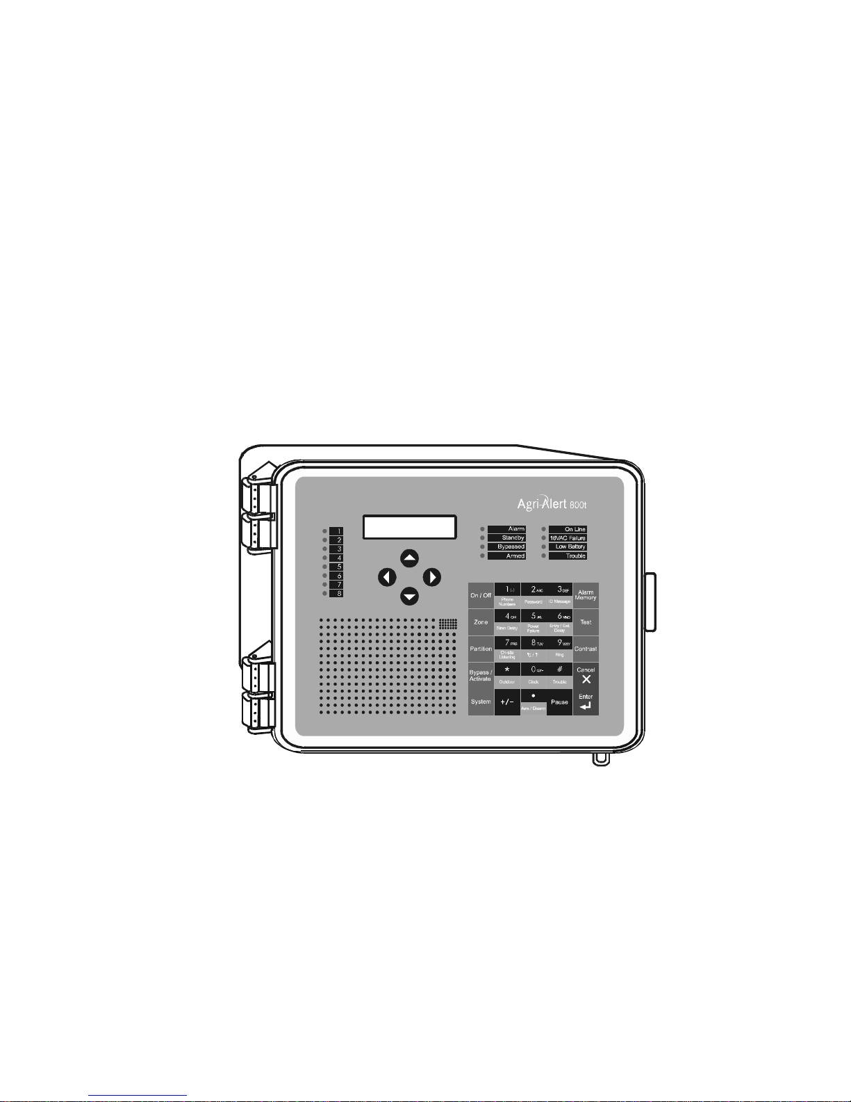
The system displays and prompts for information by using the alphanumeric screen.
The keypad is used for data entry and for enabling and disabling the various system
functions. The speaker on the front panel delivers voice messages. A built-in piezoelectric warns of illegal entries (3 short beeps) and beeps once when a valid key is
pressed. The integrated microphone on the front panel is used to record the user ID
message and provide on-site listening. The status of some subsystems is displayed
using LEDs on the front panel.
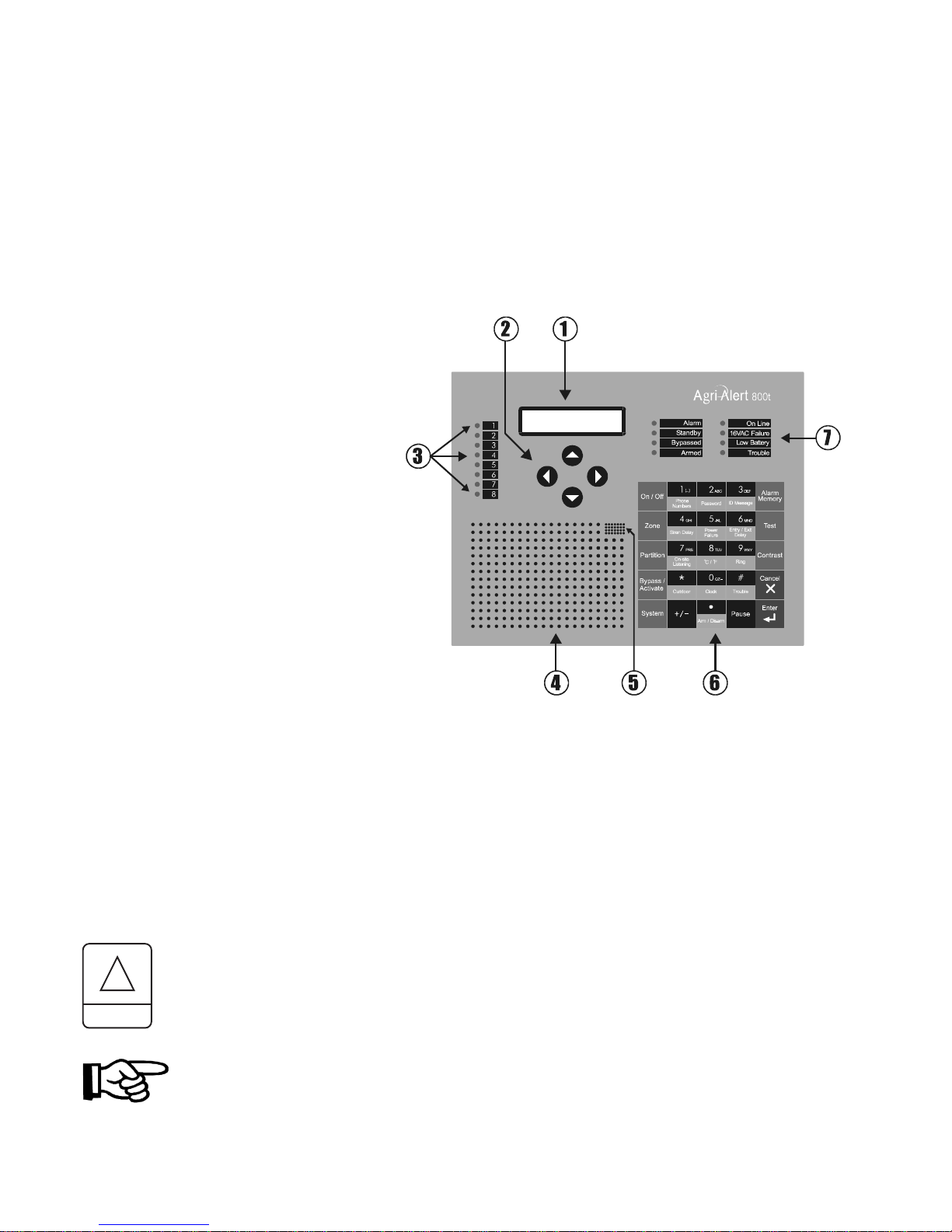
1.1 FRONT PANEL
1 - Display Screen — An alphanu-
meric display used to provide information and prompt for inputs.
2 - Cursor Keys — Used to step
through menu items during data entry and for deleting the last character entered.
3 - Zone Status LEDs — Off: DISABLED; On: ACTIVATED; Slow Blinking: BYPASSED; Fast Blinking:
ALARM.
4 - Speaker — Vocal system identifi-
cation and alarm messages.
5 - Integrated Microphone — Records the ID message and provides on-site listening
input.
6 - Keypad — User inputs and information requests.
7 - System LEDs — Status of various subsystems (see table on following page).
KEYS TO SYMBOLS IN THE MANUAL
!
WARNING
Caution. Carefully read the following text for it contains important information which, if ignored, may cause the controller to operate improperly.
Pay attention. The following text contains very useful information.
6
AA-800 / AA-800T rev.03
Page 7

1.2 MEANING OF STATUS LEDS
DELGNINAEM
MRALA
YBDNATS
.demuser
DESSAPYB
DEMRA .demraerasenozralgrubehtnehwdetavitcasiDELsihT
ENILNO .enilenohpehtsesumetsysehtnehwdetavitcasiDELsihT
erasnoitidnocmralaeromroenonehwdetavitcasiDELsihT
lenapehtfoedistfelehtnosDELenozlaudividniehT.detceted
.deepshgihtagniknilbtratsmralanisenozehtotgnidnopserroc
ehtsagnolsadegdelwonkcasimralaehtnehwffodenrutsiDELehT
ondnadespalesahemittesereht,stsixeregnolonnoitidnocmrala
.evitcaerasmralarehto
.edomybdnatsnisimetsystrelA-irgAehtnehwdetavitcasiDELsihT
mralarofstupnirosnesehtgnirotinomspotsmetsyseht,edomsihtnI
signirotinomlamronnehwffodenrutsiDELehT.snoitidnoc
ehT.dessapyberasenozeromroenonehwdetavitcasiDELsihT
otgnidnopserroclenapehtfoedistfelehtnoSDELenozlaudividni
ffodenrutsiDELehT.deepswoltagniknilbtratssenozdessapybeht
.dessapybyltnerrucerasenozonnehw
CAV61
ERULIAF
YRETTABWOL .wolsiegatlovyrettabpu-kcabehtnehwdetavitcasiDELsihT
:nehwdetavitcasiDELsihT
ELBUORT
rosnes
.tupniRLOEhtiwtcatnoc
.)remrofsnarttnuomllaw(tiucricylppus
.detcetedsimelborperawtfosa-
CAV61ehtnodetcetedsieruliafrewopanehwdetavitcasiDELsihT
ehtmorfdeviecerlangisehthtiwstcilfnocnoitarugifnocenoza-
yrdroerutarepmetanodetcetedsitiucricneporotrohseriwa-
1.3 DISPLAYING A PARAMETER
When you select a parameter to input or modify, the system begins by displaying the
current value or status of the parameter. If the message to display is longer than the
size of the window, it will be scrolled to the left. The display pauses at the end of
each screen to allow time to read the message. You can exit prematurely from a
display sequence at any time by pressing the Cancel key. This will place you in
program mode and allow you to modify the parameter values (see next section). To
exit from this function as well, press the Cancel key once again.
AA-800 / AA-800T rev.03
7
Page 8

If a parameter is not completely defined when you try to display it, the message
INCOMPLETE DATA appears on the screen. This may be an indication that the system will not behave as expected. If, for example, a zone input is not completely
configured, the system will not monitor the zone for alarm conditions. Before enabling
the system for normal operation, make sure all parameters are properly defined. In
the case of phone numbers and zones, the system will display a message every 3
seconds telling the user which zones and phone numbers are incomplete. To exit
from the warning display, press the Cancel key.
1.4 MODIFYING A PARAMETER
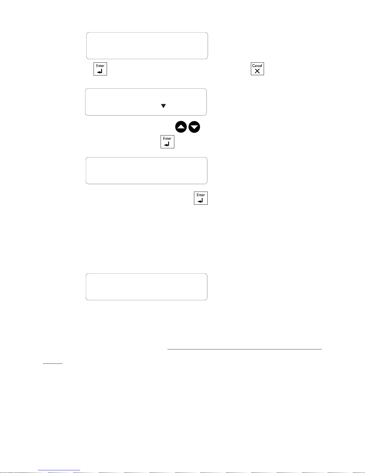
If you have selected a parameter and the display sequence is now finished, you can
begin modifying the parameter values. The following screen appears on the display:
TO MODIFY. . . . . (
↵↵
↵)
↵↵
TO QUIT. . . . . . . (X)
This screen is also displayed if the display sequence described above was cancelled
prematurely. If you want to modify the parameter values at this point, press the Enter
key to modify the parameter. The system will prompt for the information required to define the parameter. When the parameter is defined by a numerical value,
a range of possible values is displayed. For example, if you select the Exit Delay
parameter followed by MODIFY, the system responds:
RANGE FROM
(0 .. 5 MIN, 0 .. 59 SEC)
ENTER NEW DELAY
_ MIN: _ _ SEC
The number of spaces provided for input corresponds to the maximum number of
digits allowed. In this example, one space is provided for the minutes and 2 spaces
are provided for the seconds. The cursor positions itself on the first space and blinks
8
AA-800 / AA-800T rev.03
Page 9

until a digit is entered. If no response is given within 2 minutes, the system will cancel the input session and return to the Date/Time display. If more than one value is
required in the same screen (in this example: hours and minutes), press Enter after
entering the first value to step to the following one. To enter a zero value, you cannot
simply press Enter; you must type 0 Enter.
If you make a typing mistake, you can backstep using the back arrow key
underneath the display window before pressing Enter. The cursor will position itself accordingly. You can enter a negative value if this is allowed (for example, a negative temperature value) by pressing the +/- key
either before or after the digits.
After entering a value using the numerical keypad, press Enter to register the value. If
the value entered falls outside the permissible range for that parameter, the system
will beep three times and wait for you to modify the input using the back arrow key.
1.5 HOW TO USE THE MENUS
Menus are used to select a parameter or to assign a predetermined value to a parameter. If the menu is comprised of only two items, they are displayed on the screen at
QZ-
once. For example, when you press the Clock key
, followed by Enter to modify,
Clock
the following menu appears:
DATE . . . . . . . . . (1)
TIME . . . . . . . . . (2)
You simply type the number of the item to select that item (no need to press the Enter
key). When more than two menu items are involved, the system will display one item
at a time and allow the user to scroll through the menu using the up and down-arrow
keys . Each menu item is followed by an arrow symbol to locate the current
position in the menu. Once a menu item is selected, other sub-menus may appear to
further define the input. For example, if you press the Password key . After
having entered the master’s password, the following sub-menu appears:
PASSWORD
STATUS
AA-800 / AA-800T rev.03
9
Page 10

The first menu item is STATUS. The arrow following the item means you are at the
top of the menu. If you press the down-arrow , the second item appears:
The arrows indicate that menu items are to be found above and below the current
item. When you reach the end of the menu, the last item will have an up-arrow . To
select a menu item, press Enter.
PASSWORD
MASTER
1.6 SYSTEM MESSAGES
When the display is not being used by the user, the system periodically scrolls various
status messages. If temperature zones are defined, the temperatures for those zones
are displayed, as well as the low set point (L), the high set point (H) (the critical temperature (C) is also displayed if the outdoor compensation feature is enabled). When
alarms are detected, they are displayed as well, including system alarms such as a
battery failure or an unusual system temperature. When a zone or phone number is
improperly configured, it is identified along with the message “INCOMPLETE DATA”.
When burglar zones are armed, the message “BURGLAR ZONES ARMED” is displayed.
If the system clock has never been adjusted, the message “ADJUST CLOCK” is displayed. Pressing any key will stop the display sequence.
ZONE #3 75.0oF
L50 , H90 , C104
10
AA-800 / AA-800T rev.03
Page 11

1.7 BURGLAR ZONES
These zones are armed or disarmed as a group using a password. Two types of configurations are possible depending on when alarms are to be declared. In an instant
burglar zone, alarms are declared as soon as they are detected. In a delay burglar
zone, alarms are declared only after an Entry Delay has elapsed. In this way, the
authorized user has time to disarm the burglar zones before an alarm is declared. This
delay is common to all delay burglar zones. Similarly, all zones are armed after the
Exit Delay has elapsed. The key sequence for arming or disarming is as follows:
followed by the password sequence
.
When the system is armed, the system starts beeping and the screen immediately
displays a countdown of the exit delay (in minutes and seconds). The keypad is
locked at this point: the only key sequence allowed is the disarming sequence. After
the exit delay has elapsed, the system is armed and alarms are immediately declared
as they are detected for all burglar zones. The system displays the message “BURGLAR ZONES ARMED” periodically on the screen.
When an alarm occurs in a burglar zone with an entry delay, the screen displays a
countdown of the entry delay. During this time, the piezoelectric loudspeaker beeps
(the loudspeaker stops when the key sequence is entered). If no one has disarmed
the system after the entry delay has elapsed, an alarm is declared. Disarming will
affect all currently active burglar zones. The system displays the message “BURGLAR ZONES DISARMED” on the screen.
AA-800 / AA-800T rev.03
11
Page 12

1.8 ACKNOWLEDGING AN ALARM
In order to notify the Agri-Alert system that an alarm message has been received, the
alarm must be acknowledged. There are several ways of doing this. If you are onsite when an alarm is detected, enter your password (if the password feature is enabled) or simply press <1> key on the front panel to acknowledge. You can also
acknowledge an alarm over the phone when the Agri-Alert system reports the alarm
(see below) or by calling the Agri-Alert system yourself between phone dialouts (if the
intercall time is greater than zero).
Acknowledging from the keyboard:
When an alarm is detected, the following message is displayed:
ACK ALARMS
PRESS . . . . . .<1>
1. Press 1 to acknowledge. If the alarm is not acknowledged from the keyboard
within 15 seconds and the dialout sequence is enabled for the zone in alarm, the
dialout sequence will be launched. If the password feature is enabled, the system
prompts for a password before acknowledging.
ENTER PASSWORD
_ _ _ _
2. When a user acknowledges an alarm, the siren stops ringing. If the dialout sequence is completed and no acknowledgment has been received, the alarms are
automatically acknowledged but the siren continues to ring; it must be acknowledged
separately from the keypad. In this case, the following message is displayed:
ACK SIREN
PRESS . . . . . .<1>
3. Press 1 to acknowledge or 2 to exit without acknowledging. If the password
feature is enabled, the system prompts for a password before acknowledging.
ENTER PASSWORD
_ _ _ _
If passwords are enabled and an incorrect password is entered, the keypad will lock
after 4 such tries. The keypad will unlock only after the alarm is acknowledged by
phone or at the end of the dialout sequence.
12
AA-800 / AA-800T rev.03
Page 13

1.9 TELEPHONE INTERFACE
The Agri-Alert system reports alarms over the phone. It can also be accessed over
the phone to obtain status reports. When calling the Agri-Alert, make sure the Ring
Until Answer and Answering Machine parameters are set properly (see Section 3.6).
Alarms: When an alarm occurs, the Agri-Alert system reports the alarm over the
phone to all the numbers programmed in its dialout sequence (see Chapter 3). The
following section outlines the dialogue session when a number is reached. A touchtone phone must be used to respond to the system prompts. When an alarm is acknowledged, the Agri-Alert system stops dialing out. The system will hang up when
the session is over.
“Hello, this is Agri-Alert”
[User ID Message is played over the phone]
[Description of the alarm condition; for example: “Alarm Zone 1”]
“On-site Listening”
[Microphone input is sent over the phone for on-site listening if enabled]
“Enter your password to acknowledge alarm messages”
User enters four-digit password on the phone keypad. If an incorrect password is
entered, the system responds with “Wrong password”. The user has four tries in all
to enter the correct password. When the correct password is entered, the system
responds with “OK”.
“ To hang up — press 0
For on-site listening — press 2
For a new selection — press 8”
AA-800 / AA-800T rev.03
13
Page 14

User enters selection on the phone keypad
Status Reports: You can dial into the Agri-Alert system and obtain status reports over
the phone. A touch-tone phone is needed to respond to the system prompts. The
following section outlines the dialogue session when the Agri-Alert system answers
the call. The system automatically hangs up when the status report is finished.
“Hello, this is Agri-Alert”
[User ID Message is played over the phone]
“Enter your password”
User enters four-digit password on the phone keypad. If an incorrect password is
entered, the system responds with “Wrong password”. The user has four tries in all
to enter the correct password. When the correct password is entered, the system
responds with “OK”.
“ For a complete status report — press 1
For a status report on a particular zone — press 2
For on-site listening — press 4
For a new selection — press 8
To hang-up — press 0
[If a complete status report is selected, a status report is given for each zone with the
following information:
BYPASSED
DISABLED
INCOMPLETE DATA
ALARM — if zone is in alarm
ACTIVATED
TEMPERATURE READING — if zone is a temperature zone / in oC or oF depending
on current settings; ]
14
AA-800 / AA-800T rev.03
Page 15

[The status of the system is given with the following possibilities:
LOW BATTERY / BATTERY OK
SYSTEM POWER OK / SYSTEM POWER DOWN
SYSTEM TROUBLE
[System returns to the main menu]
[If a status report on a particular zone is selected, the system prompts for the zone
number]
“Enter zone number and press ‘star’ (*) ”
[A status report is given for the selected zone with the following information:
BYPASSED
DISABLED
INCOMPLETE DATA
ALARM — if zone is in alarm
ACTIVATED
TEMPERATURE READING — if zone is a temperature zone / in oC or oF depending on
current settings; ]
[System returns to the main menu]
AA-800 / AA-800T rev.03
15
Page 16

CHAPTER TWO: SYSTEM INITIALIZATION
2.1 POWER UP
When the system is powered up for the first time, the system displays the current
revision number of the software program, and the speaker plays the message: “Hello,
this is Agri-Alert!”. The default date and time are displayed. If the date and time
have never been adjusted, the system will display the message: ADJUST CLOCK
periodically to remind the user that the date and time are not correct.
2.2 SYSTEM CLOCK
Definition: The system has an internal clock that must be set when you first turn the
unit on. The time can be displayed in AM/PM format or 24-hour time. As a default,
the system clock is set to 12:00 PM JANUARY 1, 2001 in AM/PM format. The battery backup used by the Agri-Alert will keep the time and date in case of a power
failure. The system displays the message ADJUST CLOCK periodically if the date and
time have not been set.
Setting:
QZ-
1. Press the Clock key
. The current date and time are displayed.
Clock
TO MODIFY. . . . . (
↵↵
↵)
↵↵
TO QUIT. . . . . . . (X)
2. Type Enter to modify the current settings.
DATE . . . . . . . . . (1 )
TIME . . . . . . . . . (2)
3. Type 1 to change the date:
ENTER NEW DATE
_ _ / _ _ / _ _ _ _ M / D / Y
or 2 to change the time:
12 HR (AM & PM) . . . . . (1)
24 HOUR. . . . . . . . . . . . (2)
4. Type 1 for AM/PM time or 2 for 24-hour time.
16
AA-800 / AA-800T rev.03
Page 17

ENTER NEW TIME
_ _ : _ _ (HR:MIN)
Note that you must press Enter after typing each value to step to the next one. For
example, to enter the time 9:14, the sequence is: 9 Enter 14 Enter. If you selected
AM/PM time, an additional screen appears:
AM . . . . . . (1)
PM . . . . . . (2)
5. Type 1 or 2. The system updates the Date/Time display.
AA-800 / AA-800T rev.03
17
Page 18

2.3 USER ID MESSAGE
Definition: When giving status reports and alarm messages, the system identifies
itself with a voice recording provided by the user.
Setting:
1. Press the ID message key
DEF
. The current ID message is played over the
ID message
speaker on the front panel. If no ID message has yet been recorded, the system
displays NONE.
ID MESSAGE
PLAY
TO MODIFY. . . . . (
↵↵
↵)
↵↵
TO QUIT. . . . . . . (X)
2. To modify the current message, press Enter . Otherwise, press Cancel .
To Modify ID Message:
3. Type 2 to record a new ID message.
STATUS . . . . . . . (1)
MESSAGE . . . . . . (2)
4. Press the ID message key
DEF
and hold while you speak the message into the
ID message
microphone on the front panel.
FOR RECORDING
PRESS 3 AND HOLD
5. The screen will count down from a maximum of 7 seconds until the ID message
key is released.
RECORDING
07 SEC REMAINING
18
AA-800 / AA-800T rev.03
Page 19

ID MESSAGE
PLAY
5. The new message is played over the speaker and the system returns to the Date/
Time display.
To Activate / Deactivate ID Message:
STATUS . . . . . . . (1)
MESSAGE . . . . . . (2)
3. Type 1 to activate or deactivate ID message.
ENABLE . . . . . . . (1)
DISABLE. . . . . . . (2)
4. Type 1 to activate or 2 to deactivate ID message. The new status is displayed
and the system returns to the Date/Time display.
AA-800 / AA-800T rev.03
19
Page 20

2.4 PASSWORD PROTECTION
Definition: The Agri-Alert uses passwords to restrict access to the system. If the
system is locked and any key is pressed, the system prompts for a password. When
a correct password is entered, the system is temporarily unlocked. The system locks
itself automatically after one minute if, during this time, no keys are pressed. Passwords are defined as four digit numbers and are divided into two types:
(1) The Master Password is used to enable or disable the password feature. Only the
master password has this capability. In addition, the master password is required in
order to define or modify the user passwords.
(2) Up to ten User Passwords can be defined to allow different people access to the
system. A user password can temporarily unlock the system. However, a user password cannot add or change passwords, or enable or disable the password feature.
When a password is used to acknowledge an alarm, the system keeps track of the
password in the alarm memory. This information is displayed in the Alarm Memory
function when the current password is the master password (see Section 4.4). When
you first turn the unit on, the password feature is disabled and the master password is
set to 0800.
2.4.1 Modifying the Master Password
1. Press the Password key . The system displays the status of the password
feature.
STATUS: DISABLE
PASSWORD: ****
ENTER MASTER
PASSWORD: _ _ _ _
2. Enter the four digit number corresponding to the master password and press Enter
. If you do not enter the correct password at this point, you cannot continue.
The system sends the message: WRONG PASSWORD and returns to the Date/Time
display. By default, the master password is set to 0800 at the factory.
20
AA-800 / AA-800T rev.03
Page 21
TO MODIFY. . . . . (
↵↵
↵)
↵↵
TO QUIT. . . . . . . (X)
3. Type Enter to modify the master password or Cancel to exit this function.
PASSWORD
STATUS
4. Using the up and down-arrow keys , scroll the menu until the item displayed is MASTER and press Enter .
ENTER NEW
PASSWORD: _ _ _ _
5. Enter a four digit number and press Enter . If the new password you enter is
the same as the old value, the system returns to the Date/Time display. If the new
password is the same as one of the user passwords, the message USER PASSWORD
is displayed and the user is prompted for another password. Otherwise, the system
asks to confirm the new definition:
ENTER AGAIN
_ _ _ _
6. Type the four digit number and press Enter. If the number does not correspond to
the value entered previously, the system displays the message: WRONG PASSWORD
and returns to the Date/Time display without changing the current password definition. Otherwise, the system displays the message PASSWORD UPDATED and the
master password is updated to the new value.
AA-800 / AA-800T rev.03
21
Page 22

2.4.2 Enabling / Disabling the Password Feature
1. Press the Password key
. The system displays the status of the password
feature.
STATUS: DISABLE
PASSWORD: * * * *
ENTER MASTER
PASSWORD: _ _ _ _
2. Enter the four digit number corresponding to the master password and press Enter
. If you do not enter the correct password at this point, the message WRONG
PASSWORD is displayed and the system returns to the Date/Time display. By default,
the master password is set to 0800 at the factory.
TO MODIFY. . . . . (
↵↵
↵)
↵↵
TO QUIT. . . . . . . (X)
3. Type Enter to modify the status of the password feature or Cancel to
exit this function.
PASSWORD
STATUS?
4. Press Enter to select STATUS option.
ENABLE . . . . . . . (1)
DISABLE. . . . . . . (2)
5. Type 1 to enable, or 2 to disable the password feature.
STATUS: DISABLE
6. The system returns to the Date/Time display.
22
AA-800 / AA-800T rev.03
Page 23

2.4.3 Modifying the User Passwords
1. Press the Password key
. The system displays the status of the password
feature.
STATUS: DISABLE
PASSWORD: ****
ENTER MASTER
PASSWORD: _ _ _ _
2. Enter the four digit number corresponding to the master password and press Enter
. If you do not enter the correct password at this point, the message WRONG
PASSWORD is displayed and the system returns to the Date/Time display. When you
first turn the unit on, the master password is 0800.
TO MODIFY. . . . . (
↵↵
↵)
↵↵
TO QUIT. . . . . . . (X)
3. Type Enter to modify user passwords or Cancel to exit this function.
PASSWORD
STATUS
4. Press Enter to select USER option.
TO MODIFY . . . . (1)
ERASE ALL . . . . (2)
5. Type 1 to modify the user passwords.
PASSWORD
01)5698
6. The first user password is displayed in a menu. Using the up and down-arrow keys
, scroll the menu to the desired password and press Enter .
AA-800 / AA-800T rev.03
23
Page 24

PASSWORD
03)_ _ _ _
7. Type the new four-digit code. If the new password already exists, the message
PASSWORD ALREADY EXISTS is displayed. Otherwise, the message PASSWORD
UPDATED is displayed and the new password is displayed in the same menu.
PASSWORD
03)1234
8. Repeat the above sequence for each user password to modify or add. When you
are finished, press the Cancel key.
2.4.4 Erasing All User Passwords
1. Press the Password key . The system displays the status of the password
feature.
STATUS: DISABLE
PASSWORD: ****
ENTER MASTER
PASSWORD: _ _ _ _
2. Enter the four digit number corresponding to the master password and press Enter
. If you do not enter the correct password at this point, the message WRONG
PASSWORD is displayed and the system returns to the Date/Time display. By default,
the master password is set to 0800 at the factory.
TO MODIFY. . . . . (
↵↵
↵)
↵↵
TO QUIT. . . . . . . (X)
3. Type Enter to modify user passwords or Cancel to exit this function.
24
AA-800 / AA-800T rev.03
Page 25

PASSWORD
STATUS
4. Using the up and down-arrow keys , scroll the menu until the item displayed is USER and press Enter .
TO MODIFY . . . . (1)
ERASE ALL . . . . (2)
5. Type 2 to erase all user passwords.
TO ERASE . . . . . . (1)
TO QUIT . . . . . . . (2)
6. Type 1 to erase or 2 to exit without erasing. The message PASSWORDS DELETED
is displayed and the system returns to the Date/Time display.
2.5 TEMPERATURE UNITS
Definition: Temperatures can be displayed either in Fahrenheit or Celsius units. All
temperatures will be displayed according to this definition. The default is Fahrenheit.
Setting:
TUV
1. Press the oC/oF key
o
F
TO MODIFY. . . . . (
. The current value is displayed.
↵↵
↵)
↵↵
TO QUIT. . . . . . . (X)
2. Press Enter . The system changes for the alternate units.
CELSIUS. . . . . . . . (1)
FAHRENHEIT . . . . (2)
3. Type 1 to use Celsius units, or 2 to use Fahrenheit units. The new units are dis-
played and the system returns to the Date/Time display.
AA-800 / AA-800T rev.03
25
Page 26

2.6 16 VAC POWER FAILURE ALARM
Definition: This parameter defines the time the system waits before setting off an
alarm in the case of a power failure on the system 16.5VAC input (wall mount transformer). It can be enabled or disabled and the delay ranges from 0 seconds to 59
minutes 59 seconds. The default setting is ENABLED with a value of 30 minutes.
Setting:
1. Press the Power Failure
JKL
key. The system displays the current status of the
Power Failure feature along with the current delay.
TO MODIFY. . . . . (
↵↵
↵)
↵↵
TO QUIT. . . . . . . (X)
2. Type Enter
to modify the current settings or Cancel to exit this function.
STATUS . . . . . . . (1)
DELAY . . . . . . . . (2 )
To Activate / Deactivate Alarm:
3. Type 1 to modify the status.
ENABLE . . . . . . . (1)
DISABLE. . . . . . . (2)
4. Type 1 to activate, or 2 to deactivate the alarm. The new status is displayed and
the system returns to the Date/Time display.
To Adjust the Delay:
STATUS . . . . . . . (1)
DELAY . . . . . . . . (2 )
3. Type 2 to adjust the delay.
RANGE FROM
(0 .. 59 MIN, 0 .. 59 SEC)
26
AA-800 / AA-800T rev.03
Page 27

ENTER NEW DELAY
_ _ MIN: _ _ SEC
4. Enter the new delay in minutes. Press Enter. Enter the new delay in seconds.
Press Enter. The system displays the new delay values and returns to the Date/Time
display.
2.7 TEST PROCEDURE
The Agri-Alert system has the capability of testing certain functions from the keyboard. To start the test procedure, press the Test
key.
Outline of Test Procedure:
1 — TEST LEDS: The front panel LEDs are turned on and turned off, one by one, in
sequence from top to bottom and from left to right.
2 — TEST LCD: The LCD display is tested. The LCD backlight is turned off and the
display contrast is tested in steps from maximum to minimum contrast. Each character matrix is turned on, two by two, in sequence from left to right. Make sure all the
pixels in each square light up.
3 — TEST BUZZER: The internal buzzer is tested (4 buzzes).
4 — TEST SIREN: Two short beeps are sent to the siren (if a siren is hooked up).
5 — ID SYSTEM: The Agri-Alert ID message is played over the speaker. Make sure
the message is audible.
6 — ID MESSAGE: The user ID message is played over the speaker. Make sure the
message is audible. If no message has been recorded, the system displays: NONE.
7 — DIALOUT SEQUENCE: The dialout sequence is launched.
AA-800 / AA-800T rev.03
27
Page 28

2.8 TROUBLE INFORMATION
When the Trouble LED lights up on the front panel, the user can query the system for
more information.
1. Press the Trouble key. Information concerning the system trouble is dis-
played. If no system trouble has been detected, the message “NO TROUBLE” is
displayed.
ZONE #3
SHORT PROBE
TO ERASE . . . . . . (1)
TO QUIT . . . . . . . (2)
2. Type 1 to reset the trouble flag. Note that if the problem has not been corrected,
the trouble LED will remain on. Type 2 to exit this function. The system returns to
the Date/Time display.
28
AA-800 / AA-800T rev.03
Page 29

2.9 STANDBY MODE
Definition: When the system is in standby mode, no monitoring of alarm inputs is
done. The Standby LED on the display panel and the message SYSTEM ON STANDBY
are used to indicate that the system is in Standby mode. The system can automati-
cally switch to standby mode when a long power failure has drained the backup battery to a critical level. A pager message (code 8009) and a vocal message (“Low
battery; system deactivated”) are sent warning that the system is about to go into
standby mode. When normal voltage is restored to the battery, the system automatically returns to its normal mode of operations. If the system is already in standby
mode when the problem is detected, no messages are sent.
Setting:
1. Press the On/Off key
. The system prompts for a password.
ENTER PASSWORD
_ _ _ _
2. Type a four-digit password and press Enter . If an incorrect password is entered, the system responds with the message “WRONG PASSWORD” and returns to
the Date/Time display. Otherwise, the system displays the current system status:
ON — the system is running normally; OFF — the system is in standby mode.
OK
STATUS: ON
TO MODIFY. . . . . (
TO QUIT. . . . . . . (X)
3. Press Enter to modify or Cancel to quit.
ON . . . . . . . . . (1)
OFF. . . . . . . . . (2)
4. Type 1 to turn the system on, or 2 to put the system in standby mode. The new
status is displayed and the system returns to the Date/Time display.
↵↵
↵)
↵↵
AA-800 / AA-800T rev.03
29
Page 30

CHAPTER THREE: COMMUNICATION PARAMETERS
3.1 INTRODUCTION
This chapter explains the setup required for communicating alarm messages and
status reports over the telephone lines. For example, the user can dial into the AgriAlert system and obtain status reports over the phone in the form of voice messages.
The system can also be programmed to dial a series of phone numbers and deliver a
voice message when an alarm situation occurs. In order for these features to work
properly with your phone system, care must be taken to assign the proper values to
the communications parameters.
Dialout Sequence: This is a sequence of telephone numbers that are called in a specified order when an alarm has been validated by the system. When a phone number is
called, the Agri-Alert can perform different functions: deliver a voice message, send
a pager message, etc. The dialout sequence can be stopped at any time by acknowledging the alarm (see Section 1.8). Otherwise, it will continue until all the phone
numbers have been called and until the entire sequence has been called a set number
of times (equal to #of call repetitions parameter). When a busy signal is returned on a
line, the phone number is placed at the end of the sequence. If the Busy Line Tries
parameter is not zero, the system redials the busy numbers once all of the other
numbers have been called. This is repeated according to the value of Busy Line Tries.
Once the sequence is finished, the entire process is repeated until it has been completed a number of times equal to the #of call repetitions parameter. If new alarms
are detected during a dialout sequence, the entire dialout sequence is restarted.
Example: Number of telephone numbers = 5
#of call repetitions = 2
Busy Line Tries = 2
START OF DIALOUT SEQUENCE # 1
Phone number #1
Phone number #2
Phone number #3
Phone number #4
Phone number #5
connect
connect
busy
busy
connect
Phone numbers #3 and #4 are busy. They are placed at the end of the list and
redialed since Busy Line Tries = 2.
30
AA-800 / AA-800T rev.03
Page 31

Phone number #3
Phone number #4
connect
busy
Phone number #4 is still busy. Since Busy Line Tries = 2 and only one try has been
made, another call will be made.
Phone number #4
busy
Phone number #4 is still busy. It is not redialed since two tries have been made and
Busy Line Tries = 2. Since #of call repetitions= 2, the entire process is repeated
from the start.
START OF DIALOUT SEQUENCE # 2
Phone number #1
Phone number #2
Phone number #3
Phone number #4
Phone number #5
busy
connect
busy
connect
connect
Phone numbers #1 and #3 are busy. They are placed at the end of the list and
redialed since Busy Line Tries = 2.
Phone number #1
Phone number #3
END OF DIALOUT SEQUENCE
Phone numbers #1 and #3 have been reached. The dialout sequence ends since #of
call repetitions= 2 and two passes have been made to reach all the phone numbers
programmed in the system. If the alarms that set off the dialout sequence have not
been acknowledged at the end of the dialout sequence, they will automatically be
acknowledged.
connect
connect
AA-800 / AA-800T rev.03
31
Page 32

3.2 DIALING INFORMATION
Definition: These parameters are used to establish communications over the tele-
phone network when the dialout sequence is used.
3.2.1 Busy Line Tries
Definition: The number of times a phone number is called when the line is busy. This
parameter applies equally to all the phone numbers in the dialout sequence. The value
ranges from 0 to 3 tries. The default is 1 try. When a line is busy and Busy Line Tries
is greater than zero, the busy number is placed at the end of the dialout sequence.
Once all the other numbers have been dialed, the system returns to the busy numbers
and tries again, etc. If the number is reached before all the tries defined in Busy Line
Tries have been done, it is not redialed.
Note: If you have not configured the phone hookup to provide line seizure capability
and someone is using the phone when the dialout sequence is launched, the system
counts this as a try, as if all the phone numbers in the dialout sequence were busy. If
the Busy Line Tries parameter is set to zero, no other tries will be made in this case
and the alarms that set off the dialout sequence will automatically be acknowledged.
3.2.2 Message Repetitions
Definition: The number of times a voice message is delivered by the system when an
alarm condition is reported. This applies to the messages given over the phone and on
the unit speaker. The value ranges from 2 to 15 times. The default is 3.
3.2.3 Call Start Delay
Definition: The time between the validation of an alarm and the beginning of the
dialout sequence. A zero value means the dialout sequence begins immediately after
an alarm validation. When an alarm is validated, a message is delivered on-site
through the speaker on the front panel and the siren is sounded if it is enabled for the
zone in alarm. Call Start Delay allows someone on-site to acknowledge an alarm
before the dialout sequence is launched. Note that if MUTE is enabled, no message is
delivered on-site before dialout. The value ranges from 0 to 59 minutes. The default
is 1 minute.
3.2.4 Time Between Calls
Definition: The delay after a phone number has been called, before proceeding with
the next number in the dialout sequence. If someone who has received a voice message is unable to acknowledge the alarm at the time of the call, this delay will allow
time to stop the dialout sequence between calls. If the system is continuously dialing
32
AA-800 / AA-800T rev.03
Page 33

out, no calls can be made to the system to acknowledge an alarm. An intercall time
that is greater than zero makes this possible. The value ranges from 0 to 59 minutes.
The default is 1 minute.
3.2.5 Restore Calls
Definition: This feature launches the dialout sequence when a zone in alarm returns
to its normal state to advise of the change. It can be enabled or disabled and the
default setting is DISABLED.
3.2.6 # of Call Repetitions
Definition: When an alarm is validated, the system starts calling the phone numbers
stored in memory to deliver the alarm message. The # of Call Repetitions determines
the number of times this procedure is accomplished within one alarm dialout sequence. The value ranges from 1 to 7 times. The default is 7.
3.2.7 Alarm Recall Time
Definition: This parameter is used to relaunch the dialout sequence when an alarm
has been acknowledged but has not been reset. Àlarm Recall Time is the length of
time between the time the alarm is acknowledged and the time the dialout sequence
is relaunched (as long as the zone has not returned to its normal state for the duration
of reset time). If the alarm is reset before the recall time has elapsed, the planned
dialout sequence is cancelled. This parameter ranges from 0 to 12 hours, 0 to 59
minutes. The default value is 30 minutes.
3.2.8 Pause Delay
Definition: This parameter is associated with the Pause key
. This key is used to
introduce a pause in a telephone number when dialing. The Pause Delay is the length
of the pause. For example, if you need to exit a local phone network before reaching
an outside line, you can use the Pause key after entering the access code (usually ‘9’
—see Section 3.3). The range is from 1 to 255 seconds. The default is 4 seconds.
AA-800 / AA-800T rev.03
33
Page 34

3.3 PHONE NUMBERS
Definition: Phone numbers are used to report alarm conditions. Various methods are
available: voice messages, paging, beeper calls and reporting to a central monitoring
facility. Each number can contain up to 20 digits. A maximum of 8 phone numbers
can be stored by the system. The order of the numbers stored in memory defines the
dialout sequence used when an alarm is validated, i.e. the first number stored is the
first number called in an alarm.
Setting:
1. Press the Phone numbers key
. The numbers currently stored in memory are
Phone
numbers
displayed along with their parameter definitions. To stop the display and enter programming mode, press the Cancel key .
TO MODIFY. . . . . (
↵↵
↵)
↵↵
TO QUIT. . . . . . . (X)
2. Press Enter to modify.
SELECT PHONE
NUMBER (1 .. 8): _
3. Type the number of the phone number to modify and press Enter. The current
value for this phone number is displayed.
ENTER PHONE #n
4. Type the phone number. Up to 20 digits can be entered. If you press the Enter
key without entering any digits, the current phone number is erased from memory and
the message PHONE NUMBER DELETED is displayed. Special characters are available
for use with tone dialing: use the Asterisk (*)
these characters in a phone number. Each one of these characters counts as one
digit in the number. Press the Pause key to enter a pause in the dialing. This is
useful when an access code is needed to reach an outside telephone line. For example, if you dial “9” to access the telephone lines and wait 4 seconds before dialing
34
AA-800 / AA-800T rev.03
or Pound (#)
keys to enter
Trouble
Page 35

the number, you can use the Pause key feature. Set the Pause Delay parameter to
the smallest value needed for dialing pauses, for example 1 second. In the phone
number definition, press the pause key as many times as needed for the length
of the pause. For example, 9 - Pause - Pause - Pause - 1234567 will wait three seconds before dialing the seven-digit number (note that the Pause key is displayed as P
on the screen).
5. Once all the digits have been entered, press Enter. The new phone number is
displayed. The system then prompts for the type of system associated with the
number.
PHONE NUMBER OF
HOME?
The possible types are presented in a scrolling menu. Use the arrow keys to
select the type and press Enter.
Home: When this type of number is called, the system delivers a voice message
describing the alarm condition to a home telephone. Press Enter to select this option.
The system prompts for another phone number. If you are finished, press Cancel.
Cellular: When this type of number is called, the system delivers a voice message
describing the alarm condition to a cellular telephone. Press Enter to select this option. The system prompts for another phone number. If you are finished, press Can-
cel.
Beeper: This type of number is used with beeper systems. When the number is
dialed, the beeper unit simply beeps. Press Enter to select this option. The system
prompts for another phone number. If you are finished, press Cancel.
Pager: This type of number is used to access a numeric pager system. When a pager
device is paged, a code number is displayed on the pager screen. The Agri-Alert uses
this number to transmit information to the user. The code is in the form of a telephone number and contains the following information:
1SS - AAAA
AAAA: is the four-digit code describing the type of alarm.
SS: is the two-digit code of the site where the alarm occurred.
1: is a place-holder
AA-800 / AA-800T rev.03
35
Page 36

SS is the site where the Agri-Alert is installed. AAAA is an alarm code generated by
the Agri-Alert. The site number is defined by the user. For example, if two AgriAlerts are installed on separate sites, the user can identify each site with a unique
code number. In the example below, alarm code 3000 is used as a test code.
Number displayed on the pager device
Site 01
Site 02
Table 1 below defines the codes used. RESTORE ZONE means the zone returns to its
normal state.
Table 1: Pager Codes Used by the Agri-Alert System
101 - 3000
102 - 3000
EDOCREGAPGNINAEM
8001,...,2001,10018,...,2,1ENOZMRALA
8002,...,2002,10028,...,2,1ENOZEROTSER
0003TSET
36
AA-800 / AA-800T rev.03
1008YRETTABWOL
2008ERULIAFCAV61
MELBORP
DERETNUOCNE
5008TCEFEDNERIS
8008ELBUORTMETSYS
9008YBDNATSOTUAMETSYS
1009.K.OYRETTAB
DEROTSERMELBORP
2009.K.OCAV61
5009.K.ONERIS
Page 37

Figure 1 below shows the sequence of events. The Agri-Alert first dials the number
of the pager device. When the pager system responds, the Agri-Alert waits for the
voice message from the pager system to finish. In the diagram, this is called the
message delay. The diagram shows an additional delay used to ensure that the pager
system is ready to receive the code number from the Agri-Alert system. This is up to
the system (usually 3 seconds). Following this, the Agri-Alert dials the seven digit
code number or numbers to be displayed on the pager device. When configuring a
number as a pager number, the user enters the value: Message Delay when the
system prompts for the Delay for Pager.
Figure 1: Calling a Pager Number
DIALING
PAGER
NUMBER
MESSAGE
DELAY
PAGER SYSTEM ANSWERS
ADDITIONAL
DELAY
DIALING
CODE
NUMBER
Time
AGRI-ALERT TRANSMITSAGRI-ALERT DIALS
6. To configure a phone number as a pager number, use the arrow keys to scroll to
the Pager item in the menu:
PHONE NUMBER OF
PAGER?
7. Press Enter to select this option.
ENTER CODE TO
PAGE (0 .. 99): _ _
8. Enter the two digit code used to identify the site and press Enter.
DELAY FOR PAGER
(0 .. 59 SEC): _ _
9. Enter the total delay (Message Delay) used to wait for the end of the pager message and press Enter. The system prompts for another phone number. If you are
finished, press Cancel.
AA-800 / AA-800T rev.03
37
Page 38

3.4 PULSE / TONE
The system allows the user to toggle between pulse dialing and tone dialing. The
default setting is TONE.
3.5 ON SITE LISTENING
Definition: This feature allows the user to listen to on-site sounds during a status
report or an alarm report. The integrated microphone on the control panel is used for
this purpose. An external microphone can also be hooked up for on-site listening.
Only one microphone can be used at a time. The user can enable or disable on-site
listening and adjust the listening time. The default setting is DISABLED with a listening time of 30 seconds.
Setting:
1. Press the On-site Listening key
PRS
. The status (Enabled/Disabled) is displayed,
On-site
Listening
followed by the current listening time.
STATUS: ENABLE
DELAY: 10 SEC.
TO MODIFY. . . . . (
↵↵
↵)
↵↵
TO QUIT. . . . . . . (X)
2. Press Enter to modify or Cancel to quit.
STATUS . . . . . . . .(1)
DELAY . . . . . . . . (2)
To Activate / Deactivate On-site Listening:
3. Type 1 to modify the status of on-site listening.
ENABLE . . . . . . . (1)
DISABLE. . . . . . . (2)
4. Type 1 to enable, or 2 to disable on-site listening. The new status is displayed,
and the system returns to the Date/Time display.
38
AA-800 / AA-800T rev.03
Page 39

To Adjust Listening Time:
STATUS . . . . . . . .(1)
DELAY . . . . . . . . (2)
3. Type 2 to adjust the listening time.
RANGE FROM
(0 .. 59 SEC)
ENTER NEW DELAY
_ _ SEC
4. Enter the new delay and press Enter. The system displays the new delay setting
and returns to the Date/Time display.
AA-800 / AA-800T rev.03
39
Page 40

3.6 RINGS / ANSWERING MACHINE
Definition: The user can define the number of rings before an incoming call is an-
swered, for example for a status report. The values range from 1 to 20 rings. The
system can also be configured to connect a telephone answering device on the same
phone line. When this feature is enabled, the Agri-Alert system answers incoming
calls only if a special ring sequence is followed. Otherwise, the telephone answering
device takes the call after a preset number of rings. The special ring sequence used
to connect to the Agri-Alert system is as follows:
— dial the Agri-Alert phone number and hang-up after one ring
— redial the number after 30 seconds have elapsed
— after the first ring, the Agri-Alert system will answer the call
If the answering machine is set to answer after one ring, it must be set to more than
one ring for this sequence to work. If an answering machine is not used, any calls
made to the Agri-Alert system are answered after the number of rings defined. By
default, the number of rings is set to 8 and the answering machine feature is disabled.
Setting:
1. Press the Ring key
. The current parameter setting is displayed.
Ring
8 RINGS
TO MODIFY. . . . . (
↵↵
↵)
↵↵
TO QUIT. . . . . . . (X)
2. Press Enter to modify the value or Cancel to quit.
DO YOU HAVE ANSWERING MACHINE?
YES . . . . . . . . . . (1)
NO . . . . . . . . . . (2)
To Enable / Disable Answering Machine:
3. Type 1 to use an answering machine with the Agri-Alert system. The system
returns to the Date/Time display.
40
AA-800 / AA-800T rev.03
Page 41

To Set Number of Rings:
3. Type 2 to disable the answering machine feature and set the number of rings
before the Agri-Alert system answers a call.
RANGE FROM
(1 .. 20)
ENTER NEW NUMBER
OF RINGS: _ _
4. Type the new number of rings and press Enter. The system displays the new
value and returns to the Date/Time display.
AA-800 / AA-800T rev.03
41
Page 42

CHAPTER FOUR: ALARM PARAMETERS
4.1 ALARM VALIDATION: SUMMARY OF EVENTS
NOITCAESNOPSERSRETEMARAP
SIMRALANA.1
.DETCETED
nehW
SIMRALANA.2
.DETADILAV
nehW
emiTnoitingoceR
.dehcaersi
emiTnoitingoceR
litnunoitadilavecnis
.detavitcasiti,tuptuoneris
yaleDtratSllaC
ybdetarapessillachcae;dellac
.yaledsllacneewteb
fo
TUOLAID.3
.SNIGEB
otgnidrocca
.snoititepeRegasseM
seirTysuB
foeulavehtotgnidrocca
despaleemitehtserusaemmetsysehT
litnumralaehtfonoitcetedehtecnis
A,despalesah
otetis-nodereviledsiegassemeciov
.)delbanesiETUMsselnu(mralaehttroper
despaleemitehtserusaemmetsysehT
yaleDtratSllaC
si
ehtotdetcennocsinerisafI.dehcaer
hcae,despalesah
siecneuqestuolaidehtnirebmunenohp
etuM
emiTnoitingoceR
yaleDtratSllaC
emiT
yranidronasisihtfI
egassemeciova,rebmunralullecroenohp
ehtsemitforebmunehT.dereviledsi
eulavehtnosdnepeddereviledsiegassem
etumehtfI
oslasiegassemsiht,delbasidsinoitcnuf
na,rebmunregaparoF.etis-nodereviled
.metsysregapehtottnessiedocmrala
sitinurepeebeht,rebmunrepeebaroF
ehttadecalperasrebmunysuB.dellac
delaiderdnaecneuqestuolaidehtfodne
seunitnoctuolaiD.
ro,degdelwonkcasimralaehtrehtielitnu
detucexeneebsahecneuqestuolaideht
seirTysuB
deepSlaiD
sllaCneewteBemiT
snoititepeRegasseM
snoititepeRllaCfo#
noitceteDenoTlaiD
yeKyaleDesuaP
llaCfo#
.snoititepeR
sinerisafI.deppotssiecneuqestuolaiD
siti,tuptuonerisehtotdetcennoc
SIMRALA.4
.DEGDELWONKCA
fidnaenohpehtrevo
.gninetsiletis-no
degdelwonkcasawmralaehtfI.deppots
gninetsiLetiSnO
si
etis-nootnetsilnacresueht,delbane
rofdenifedyaledehtotgnidroccasdnuos
gninetsiLetiSnO
42
AA-800 / AA-800T rev.03
Page 43

4.2 SYSTEM ALARMS
Definition: The Agri-Alert system detects certain internal alarm conditions that be-
have in the same way as a zone alarm, i.e. the siren is activated, the dialout sequence
is launched, etc. These alarms have a fixed recognition time of 2 minutes; the reset
time is set to 45 minutes if no one is present or 2 minutes if someone is present (i.e.
the display backlight is turned on – the reset time for low battery and system trouble
alarms is always 45 minutes). The table below describes these alarms:
Table 2: System Alarms
EPYTMRALAGNINAEM
YRETTABWOL
NAHTSSELSIEGATLOVYRETTAB
.NIM2NAHTEROMROFV5.01
/NWOLB8FESUFNERIS
TCEFEDNERIS
NERIS/ELBUORTERIWNERIS
NOITCNUFLAM
ENOZNOELBUORTGNIRIW
ELBUORTMETSYS
METSYSROSTUPNI
NOITCNUFLAM
AA-800 / AA-800T rev.03
43
Page 44

4.3 OUTDOOR TEMPERATURE COMPENSATION ON TEMPERATURE ALARMS
The outdoor temperature compensation feature is only available on
AA-800T models.
Definition: In situations where the outdoor temperature is high, the room temperature
will rise as warm air enters the building through ventilation inlets. If the high set point
defined above is not adjusted to take this into account, a high temperature alarm may
be needlessly set off. To avoid this situation, the system can compensate for high
outdoor temperatures when monitoring temperature alarms. When this feature is
activated and the outdoor temperature is close to the high set point, the room temperature is monitored with respect to the outdoor temperature. An alarm is set off
only if the room temperature rises above the outdoor temperature by a certain value
called the offset. In addition to this, the system also uses a critical high temperature
as an absolute limit on room temperature. When room temperature reaches the critical high temperature, an alarm is set off. To use this feature, an outdoor temperature
probe must be connected to a temperature zone. The probe must have a pale-colored
(white or grey) PVC casing and should be installed near an air intake.
Critical Temperature: The absolute temperature limit for room temperatures. When
the room temperature reaches this point, an alarm is set off, no matter what the
outdoor temperature is. The default setting is 95°F (35°C).
Offset: In general, the room temperature is greater than the outdoor temperature by a
certain number of degrees, called the offset. The offset determines when an alarm is
set off. It is the number of degrees the room temperature can rise above the outdoor
temperature without setting off an alarm. The default setting is 5°F (2.8°C).
The diagram below shows when the outdoor temperature compensation feature takes
effect (if it has been enabled by the user). When the outdoor temperature is greater
or equal to the high set point less the offset, the system uses the outdoor temperature
as the reference point for monitoring high temperature alarms.
Figure 2: Outdoor Temperature Compensation
Temperature
High Set Point
Outdoor T°
Normal Alarm
Monitoring
Outdoor T°
Compensation
OFFSET
44
AA-800 / AA-800T rev.03
Time
Page 45

When outdoor temperature compensation is in effect, the system monitors (i) the
room temperature with respect to the critical temperature (this check has the highest
priority); (ii) the room temperature with respect to the outdoor temperature. The
figure below illustrates the first case:
Figure 3: Critical Temperature Monitoring
Temperature
Critical T°
Room T°
Alarm 1
Alarm 2
Alarm 3
ALARM
NO ALARM
Time
In the second case, the system monitors the difference between the room and outdoor temperatures. When this difference is greater than the offset, an alarm is set
off.
Figure 4: Monitoring the Indoor-Outdoor Temperature Difference
Temperature
Room T°
Outside T°
Alarm 1
Alarm 2
OFFSET
Time
AA-800 / AA-800T rev.03
45
Page 46

To Activate / Deactivate the Outdoor Temperature Compensation (AA-800T Model
Only):
1. Press the Outdoor
key. The system displays the current status, outdoor
probe assignment and temperature offset value.
OUTDOOR
PARAMETERS
STATUS
DISABLE
OUTDOOR PROBE
#1
OFFSET TEMP.
5.0°F
TO MODIFY. . . . . (
↵↵
↵)
↵↵
TO QUIT. . . . . . . (X)
2. Press Enter
to modify the outdoor temperature compensation settings or
Cancel to quit. The system displays a menu.
STATUS. . . . . . . (1)
OFFSET TEMP . . . (2)
3. Type 1 to change the status of the outdoor compensation feature.
ENABLE. . . . . . . . (1)
DISABLE . . . . . . . (2)
4. Type 1 to enable, or 2 to disable outdoor compensation feature. The new setting
is displayed and the system returns to the Date/Time display.
46
AA-800 / AA-800T rev.03
Page 47

To Set the Offset Temperature (AA-800T Model Only):
1. Press the Outdoor
key. The system displays the current status, outdoor
probe assignment and temperature offset value.
OUTDOOR
PARAMETERS
STATUS
DISABLE
OUTDOOR PROBE
#1
OFFSET TEMP.
5.0°F
TO MODIFY. . . . . (
↵↵
↵)
↵↵
TO QUIT. . . . . . . (X)
2. Press Enter
to modify the outdoor temperature compensation settings or
Cancel to quit.
STATUS. . . . . . . . (1)
OFFSET TEMP . . . (2)
3. Type 2 to change the offset temperature. By default, the offset is 5°F (2.8°C).
RANGE FROM
(0°F..36°F)
OFFSET TEMP.
_ _ _ _ °F
4. Enter the offset temperature and press Enter. The system displays the new setting and returns to the Date/Time display.
AA-800 / AA-800T rev.03
47
Page 48

4.4 ALARM MEMORY
Definition: Each alarm condition detected by the Agri-Alert system is recorded in
memory for future reference. The parameters stored in memory are the zone number,
the alarm type, the time, the date, the user who acknowledged the alarm (if a user is
defined) and the time and date of acknowledgement. The system stores only the last
ten alarms in memory. It should be noted that if the zones are reconfigured at any
time, the alarm memory recorded up to that time is erased.
If the password feature is enabled, the system requires a password before acknowledging an alarm from the keypad (acknowledging over the phone always requires a
password). This password will appear in the alarm memory listing only if the master
password is currently logged onto the system. If a user is logged on, the system will
not identify the password that acknowledged the alarm. If, at the time the alarm was
acknowledged, the password feature was not enabled, the alarm memory listing will
not contain the password that acknowledged the alarm.
To access alarm memory, press the Alarm Memory
key. If no alarm events are
presently stored in memory, the system returns the message: NONE. To step to the
next alarm entry while the current entry is still scrolling on the display, press the
Cancel key .
Examples: In the first example, the password of the user that acknowledged the
alarm is not identified. This means either no password was entered when the alarm
was acknowledged or the current password is not the master password.
SIREN OUTPUT
DEFECTED AT 12:47 PM ON AUG 14 2000
ACK AT 01:16 PM ON AUG14 2000
In the second example, the password is identified. This means that a password was
entered when the alarm was acknowledged and the current password is the master
password.
ZONE #1
HI TEMPERATURE AT 12:47 PM ON AUG 14 2000
ACK BY 1234 AT 01:16 PM ON AUG14 2000
48
AA-800 / AA-800T rev.03
Page 49

4.5 ZONE STATUS DISPLAY
Definition: You can display zone status information at any time by using the Zone
key. This key also allows you to modify certain zone parameters such as set points
without having to reconfigure the zone. The current zone definition and data readings
are displayed along with the zone status. The information displayed depends on the
type of zone:
1. Dry contact zones: OPEN / CLOSE, recognition time
2. Temperature zones: temperature reading, set points, critical temperature
and recognition time.
3. Pulse count zones: pulse count, set points and observation length
When using the outdoor temperature compensation feature, the zone assigned to the
outdoor probe is identified by the message OUTDOOR PROBE (See Section 4.3). The
different zone states are summarized below:
1. DISABLED: When a zone is first configured, it is in disabled state, until the
user activates it using the Activate key. When a zone is disabled, no alarms
are detected on the zone input. The zone LED on the front panel is turned off.
2. ACTIVATED: Alarm detection is enabled on the zone input. The zone LED
on the front panel is turned on. To change the state to BYPASSED, use the
Bypass/Activate key.
3. BYPASSED: No alarm detection is performed on the zone input. The LED on
the front panel blinks slowly. To change the state to ACTIVATED, use the
Bypass/Activate key.
4.5.1 Viewing and Modifying Dry Contact Zones
The recognition time of a dry contact zone can be modified using the Zone key as
follows. Refer to section 3.2 of the installation manual for further information about
dry contact zones and recognition time.
1. Press the Zone key
Zone
.
SELECT ZONE
(1 .. 8): _
2. Enter the number of the zone. The state of the zone is displayed, followed by the
status.
ZONE # 1
75.0 oF
AA-800 / AA-800T rev.03
49
Page 50

ZONE # 5
STATUS : ACTIVATED
TO MODIFY. . . . . (
↵↵
↵
↵↵
)
TO QUIT. . . . . . . (X)
3. Press Enter to modify the recognition time of the dry contact zone.
RANGE FROM
(0 .. 59 HR, 0.. 59 MIN, 0 .. 59 SEC)
RECOGNITION TIME
_ _ : _ _ : _ _
4. Enter the recognition time and press Enter. The system displays the new setting
and returns to the Date/Time display.
4.5.2 Viewing and Modifying Temperature Zones
The Zone key allows to modify the set points of temperature zones and their recognition time. Refer to section 3.2 of the installation manual for further information about
temperature zones and recognition time.
1. Press the Zone key
Zone
.
SELECT ZONE
(1 .. 8): _
2. Enter the number of a temperature zone. The state of the zone is displayed, followed by the status.
ZONE # 6
75.0°F
ZONE # 6
STATUS : ACTIVATED
SET POINTS
LO: 55.0 oF, HI: 85.0 oF
50
AA-800 / AA-800T rev.03
Page 51

CRITICAL TEMP.
95.0 oF
TO MODIFY. . . . . (
↵↵
↵)
↵↵
TO QUIT. . . . . . . (X)
3. The critical temperature is displayed only if the outdoor temperature compensation
feature is activated (see Section 4.3) (on AA-800T models only). Press Enter to
modify the current set points and/or recognition time or press Cancel to quit.
RECOGNITION . . . (1)
SET POINTS . . . . . (2)
Modifying Recognition Time
4. Press 1 to modify the recognition time.
RANGE FROM
(0 .. 59 HR, 0.. 59 MIN, 0 .. 59 SEC)
RECOGNITION TIME
_ _ : _ _ : _ _
5. Enter the recognition time and press Enter. The system displays the new setting
and returns to the Date/Time display.
Modifying Temperature Set Points
4. Press 2 to modify the temperature set points.
TEMPERATURE
SET POINTS
LO SET POINT
RANGE FROM
(-40.0oF .. 149.0 oF)
AA-800 / AA-800T rev.03
51
Page 52

LO SET POINT
o
_ _ _ _ _
F
5. This is the lower value of the normal temperature range. It ranges from -40 oF to
149 oF (-40 oC to 65 oC) with an accuracy of 0.1 oF (0.1 oC). Enter the low set point
and press Enter. To enter a negative value, use the key, either before or after
the digits.
HI SET POINT
RANGE FROM
o
(X°F .. 149.0
F)
HI SET POINT
_ _ _ _ _ oF
6. This is the upper value of the normal temperature range. It ranges from the low
set point to 149 oF (65 oC) with an accuracy of 0.1 oF (0.1 oC). Enter the high set
point and press Enter. To enter a negative value, use the key, either before or
after the digits. The high set point must be greater than the low set point.
CRITICAL TEMP.
RANGE FROM
(XoF .. 149.0 oF)
CRITICAL TEMP.
_ _ _ _ _ oF
7. The critical temperature is displayed only if the outdoor temperature compensation
feature is activated (see Section 4.3) (on AA-800T model only). It is the absolute
temperature limit for room temperatures. It is used in conjunction with the outdoor
temperature compensation feature. When the room temperature reaches this point
and the outdoor temperature compensation feature is enabled, an alarm is set off, no
52
AA-800 / AA-800T rev.03
Page 53

matter what the outdoor temperature is. It ranges from the high set point to 149 oF
(65 oC) with an accuracy of 0.1 oF (0.1 oC). Enter the critical temperature and press
Enter. To enter a negative value, use the key, either before or after the digits.
The system displays the current zone temperature and returns to the Date/Time display.
4.5.3 Viewing and Modifying Pulse Count Zones
The Zone key allows to modify the lo and hi set points of pulse count zones. It is also
possible to change the observation length. Refer to section 3.2 of the installer manual
for further information about pulse count zones.
1. Press the Zone key
Zone
.
SELECT ZONE
(1 .. 8): _
2. Enter the number of a pulse count zone. The state of the zone is displayed, followed by the status.
ZONE # 7
10 PULSES
ZONE # 7
STATUS : ACTIVATED
SET POINTS
LO:3 PULSES, HI:15 PULSES
OBSERVATION LENGTH
00 : 05 : 30
TO MODIFY. . . . . (
TO QUIT. . . . . . . (X)
3. Press Enter to modify the pulse count zone set point and observation length.
PULSE COUNT
PULSE SET POINT
↵↵
↵)
↵↵
AA-800 / AA-800T rev.03
53
Page 54

RANGE FROM
(0 .. 254)
LO SET POINT
_ _ _ PULSES
4. This is the lower number of pulses allowable during the observation length. It
ranges from 0 to 254. Enter the low set point and press Enter.
HI SET POINT
_ _ _ PULSES
5. This is the highest number of pulses allowable during the observation length. It
ranges from 0 to 254. Enter the high set point and press Enter.
OBSERVAT. LENGTH
RANGE FROM
(0 .. 59HR, 0 .. 59MIN, 0 ..59 SEC)
OBSERVAT. LENGTH
_ _ : _ _ : _ _
6. Enter the observation length and press Enter. The system displays the new setting
and returns to the Date/Time display.
54
AA-800 / AA-800T rev.03
Page 55

4.6 PARTITIONS
Definition: Zones can be grouped into partitions, relating alarm systems located in the
same area. This makes it easy to activate or bypass several zones at once, if they
are physically located in the same area or if they are logically connected together.
Figure 5 below gives an example of this. If, for example, the animals in Building 2 are
evacuated, the alarm systems for the entire building can be turned off at once. Up to
8 different partitions can be programmed into the system. If changes are made to a
partition, all zones associated with the partition are deactivated. Note that burglar
zones cannot be included in a partition. If a zone belonging to a partition is redefined
as a burglar zone, it will be removed from the partition.
Figure 5: Example of Partitioning
Temperature Sensors
BUILDING 1
Partition 1
ZONE 1
ZONE 2
ROOM 1 ROOM 2
ZONE 5
ROOM 3
BUILDING 2
Agri-Alert
800t / 800
ZONE 3
ROOM 4
ZONE 4
Partition 2
Setting:
1. Press the Partitions key . The partitions currently stored in memory are displayed. To stop the display, press the Cancel key .
TO MODIFY. . . . . (
↵↵
↵)
↵↵
TO QUIT. . . . . . . (X)
2. Press Enter to modify.
ENTER PARTITION
(1 .. 8): _
3. Type the number of the partition to modify and press Enter.
AA-800 / AA-800T rev.03
55
Page 56

To Add a Zone:
PARTITION #1
ADD ZONE
3. The different options are presented in a scrolling menu. Use the up and down
arrow keys to select ADD ZONE and press Enter.
#1) 1, 2, 3
ADD ZONE: _ _
4. The zones currently included in the partition are displayed on the first line. Enter
the number of the zone to add to the partition and press Enter. If you choose a zone
that is already assigned to another partition, the system responds with the message:
ZONE IS ALREADY SELECTED. The system displays the new partition definition.
PARTITION #1
ZONE #1, 2, 3, 4
To Delete a Zone:
PARTITION #1
DEL ZONE?
3. The different options are presented in a scrolling menu. Use the up and down
arrow keys to select DEL ZONE and press Enter.
#1) 1, 2, 3, 4
DEL ZONE: _
4. Enter the number of the zone to delete from the partition and press Enter. The
system displays the new partition definition.
PARTITION #1
ZONE #1, 2, 3
56
AA-800 / AA-800T rev.03
Page 57

To Delete a Partition:
PARTITION #1
DEL PARTITION ?
3. The different options are presented in a scrolling menu. Use the up and down
arrow keys to select DEL PARTITION and press Enter. The system displays
the message PARTITION DELETED.
After Making a Change:
The system prompts to make more changes or to end the session:
TO CONTINUE . . . . . . .(1)
TO END . . . . . . . . . . . . (2)
Type 1 to make more changes. Type 2 to exit this function; the system returns to
the Date/Time display.
4.7 BYPASS / ACTIVATE FUNCTION
Definition: The Agri-Alert system can activate or bypass individual zones and parti-
tions. When a zone is bypassed, no alarm detection is performed on the zone input.
When a zone becomes active, the corresponding LED on the left hand side of the front
panel turns on and the system monitors the alarm input connected to the zone. When
an alarm occurs, the LED for the zone where an alarm was detected starts blinking
rapidly. The relevant data are recorded in alarm memory and the dialout sequence is
launched. Note that burglar zones cannot be activated in this way although they can
be bypassed one at a time. Burglar zones are activated with the dot key and a password.
AA-800 / AA-800T rev.03
57
Page 58

To change the status of a zone:
1. Press the Bypass / Activate key.
ZONE . . . . . . . . . (1)
PARTITION . . . . . (2)
2. Type 1 to change the status of a zone;
ENTER ZONE
(1 .. 8): _
3. Type the number of the zone and press Enter. If the zone is not properly configured, the system responds with the message: INCOMPLETE DATA.
ACTIVATE. . . . . . ( 1)
BYPASS . . . . . . . (2)
4. Type 1 to activate, or 2 to bypass the zone. The new state of the zone is displayed. If you have just activated a zone, the LED associated with the zone will turn
on.
To change the status of a partition:
1. Press the Bypass / Activate key.
ZONE . . . . . . . . . (1)
PARTITION . . . . . (2)
2. Type 2 to change the status of a partition.
ENTER PARTITION
(1 .. 8): _
3. Type the number of the partition and press Enter. If the partition does not exist,
the system responds with the message: PARTITION NONE.
ENABLE. . . . . . . . (1)
DISABLE . . . . . . . (2)
58
AA-800 / AA-800T rev.03
Page 59

4. Type 1 to enable, or 2 to disable the partition. The new state of the zone is displayed and the system returns to the Date/Time display. If you have activated a
partition, all the LEDs associated with the zones in the partition turn on.
4.8 ENTRY DELAY
Definition: The time needed to disarm the burglar zones when entering the site before
an alarm is set off. This applies to all delay burglar zones and ranges from 0 to 5
minutes, 59 seconds. The default is 30 seconds. The entry delay countdown begins
when an alarm is detected in a burglar zone with an entry delay.
Setting:
1. Press the Entry/Exit Delay key
Entry/Exit
Delay
.
ENTRY DELAY . . . . . . .(1)
EXIT DELAY . . . . . . . . . (2)
2. Type 1 to adjust the Entry Delay.
ENTRY DELAY
0 MIN, 30 SEC
TO MODIFY. . . . . (
↵↵
↵)
↵↵
TO QUIT. . . . . . . (X)
3. Press Enter to modify the current settings, or Cancel to quit.
RANGE FROM
(0 .. 5 MIN, 0 .. 59 SEC)
ENTER NEW DELAY
_ MIN : _ _ SEC
4. Enter the new delay and press Enter. The new entry delay is displayed and the
system returns to the Date/Time display.
AA-800 / AA-800T rev.03
59
Page 60

4.9 EXIT DELAY
Definition: The time needed to exit the site before the system starts monitoring the
alarm inputs. This applies only to burglar zone and is common to all zones. It ranges
from 0 to 5 minutes, 59 seconds. The default is 30 seconds.
Setting:
1. Press the Entry/Exit Delay key
Entry/Exit
Delay
.
ENTRY DELAY . . . . . . .(1)
EXIT DELAY . . . . . . . . . (2)
2. Type 2 to adjust the Exit Delay.
EXIT DELAY
0 MIN, 30 SEC
TO MODIFY. . . . . (
↵↵
↵)
↵↵
TO QUIT. . . . . . . (X)
3. Press Enter to modify the current settings, or Cancel to quit.
RANGE FROM
(0 .. 5 MIN, 0 .. 59 SEC)
ENTER NEW DELAY
_ MIN : _ _ SEC
4. Enter the new delay and press Enter. The new exit delay is displayed and the
system returns to the Date/Time display.
60
AA-800 / AA-800T rev.03
Page 61

4.10 SIREN DELAY
Definition: When an alarm condition is detected, and if the siren is enabled for the
zone in alarm, the system activates the siren. This parameter defines the time the
siren will sound. The value ranges from 1 to 20 minutes. The default is 5 minutes.
Setting:
1. Press the Siren Delay key
. The current siren delay is displayed.
Siren delay
5 MIN
TO MODIFY. . . . . (
↵↵
↵)
↵↵
TO QUIT. . . . . . . (X)
2. Press Enter .
RANGE FROM
(1 .. 20 MIN)
ENTER NEW DELAY
_ _ MIN
3. Enter the new delay and press Enter. The system returns to the Date/Time display.
AA-800 / AA-800T rev.03
61
Page 62

TROUBLESHOOTING GUIDE
MELBORPSNOITULOS
.nosnrutsyawlaDELMRALAehT .nwolbsiesufhcihwenimretedotyromeMmralAkcehC-1
tnemecalperrofAxidneppAnielbatehtotrefeR
ehtwollof,esufnerisehthtiwsimelborpehtfI.snoitacificeps
:wolebspets
enimretedotyrt,nwolbsiesuffI.)8F(esufnerisehtkcehC-2
siht-yticapacesufesaercnitonoD.gnicalpererofebyhw
54siemitteserehttahtrebmemeR.drazaherifaebdluoc
sienoemosfisetunim2dnatneserpsienoonfisetunim
.tneserp
rotsisera,slanimretnerisehtotdetcennocsinerisonfI-3
ΩΩ
Ω
ΩΩ
.)1.3.3.1noitces(launamnoitallatni
.evitcefedebyamnerisroeriwnerisehT-5
ΩΩ
Ω
ΩΩ
ehteeS.)W½,k5.1(ecalpstinidetcennocebtsum
W½,k5.1adda,hgihotsiecnadnepminerisehtfI-4
.elbissopsanerisehtotesolcsa,tiurcicnerisehtotrotsiser
.nosnrutDELELBUORTehT ehtxiF.noitamrofnieromrofyekELBUORTehtsserP-1
.KOsirewoplacirtceledna
.relaedruoytcatnoc,stsisrepmelborpehtfI-6
teserotunemehtniESAREesoohcdnaelbissopfimelborp
.galfelbuorteht
.relaedruoytcatnoc,stsisrepmelborpehtfI-2
nosnrutDELERULIAFCAV61ehT
.drazaherifaebdluoc
.gniriwdnaremrofsnartllawehtkcehC-2
.)muminimCAV61(slanimret
.relaedruoytcatnoc,stsisrepmelborpehtfI-4
enimretedotyrt,nwolbsiesuffI.7Fdna6FsesufkcehC-1
siht-yticapacesufesaercnitonoD.gnicalpererofebyhw
tupniCAV61ehttaegatlovkcehcotretemtlovaesU-3
62
AA-800 / AA-800T rev.03
Page 63

MELBORPSNOITULOS
nosnrutDELYRETTABWOLehT
.KOsirewoplacirtceledna
.ffosnrutthgilkcabyalpsidehtecnoylnodetrats
siretnuoceht;setunim54siemitteserehttahtrebmemeR-1
gnitcelesdnayekmetsySehtgnisserpybegatlovyrettabkcehC-2
egatlovlamroN.unems'xuAmargorPehtmorfYRETTABPUKCAB
.V41otV21morfdaerdluohs
erofebyhwenimretedotyrt,nwolbsiesuffI.82FesufkcehC-3
erifaebdluocsiht-yticapacesufesaercnitonoD.gnicalper
.drazah
.gniriwdnaremrofsnartllawehtkcehC-4
slanimrettupniCAV61ehttaegatlovkcehcotretemtlovaesU-5
.)muminimCAV61(
.yrettabehtotgniriwehtkcehC-5
.relaedruoytcatnoc,stsisrepmelborpehtfI-6
ybedomybdnatSotniseogmetsyS
.flesti
kcehC.)yekffO/nOehtgnisu(edomybdnatselbasiDyrettab
PUKCABgnitcelesdnayekmetsySehtgnisserpybegatlov
dluohsegatlovlamroN.unems'xuAmargorPehtmorfYRETTAB
evobasnoitcurtsniwollof,wolsiegatlovehtfI.V41otV21morfdaer
.deleruliafCAV61rof
siENILDEBRUTSIDegassemehT
.tuoslaidmetsysehtnehwdeyalpsid
ehtgnilbaneyrt,eruziesenilrofderiwneebtonsahmetsysruoyfI
ENILgnitcelesdnayekmetsySehtgnisserpybnoitcnuferuziesenil
.)launamnoitallatsniehtfo2.1.4noitces(unemehtmorfERUZIES
.tsetrotinomkooh-ffoehtetavitcaedlliwsihT
saevahebtonseodenilenohP
.detcepxe
.relaedruoytcatnoc
dnakcajllawehtmorfgulpenohpmetsystrelA-irgAehtgulpnU
AA-800 / AA-800T rev.03
63
Page 64

APPENDIX A: FUSE TYPES
ESUF
REBMUN
7F,6F
8FMM02x5WOLBWOLSA2tuptuOneriS19601-01
82FMM02x5WOLBWOLSA5yrettaBpu-kcaB09601-01
EPYTESUFNOITCNUF
MM02x5WOLBTSAFA3
)remrofsnartAV04rof(
rewoPCA
noitcennoC
APPENDIX B: MAXIMUM WIRE LENGTHS
ERIW
EPYT
GWA61#)'028(m052)'0656(m0002)'461(m05
ERUTAREPMET
EBORP
SEBORPREHTONERIS
TRAP
REBMUN
52701-01
GWA81#)'014(m521)'5624(m0031)'89(m03
GWA02#)'502(m26)'4262(m008.A.N
GWA22#)'201(m13)'0461(m005.A.N
APPENDIX C: BACKUP BATTERY LIFE SPAN
TNERRUC)Am(
o
0
egrahcmuminimAm053
DESUTONTUPTUONERIS
egrahcmumixamAm0053
Am0051-NERIS
23/C
o
F02
sruoh71sruoh02
ruoh2/1ruoh1
o
ERUTAREPMET
o
86/C
F
64
AA-800 / AA-800T rev.03
Page 65

GLOSSARY OF TERMS
ACKNOWLEDGEMENT: The indication to the system that an alarm message has been
received. The alarm acknowledgement stops the dialout sequence and the siren and
can be executed over the phone or from the keypad.
ALARM MEMORY: A record of the ten last alarms stored by the system (see Section
4.4).
ALARM RECALL TIME: Alarm recall time is the length of time between the time the
alarm is acknowledged and the time the dialout sequence is relaunched (as long as
the zone has not returned to its normal state for the duration of reset time). (see
Section 3.2.7).
BURGLAR ZONE: A zone used for detecting break-ins. Delays are provided to allow
authorized entries and exits. All burglar zones are armed or disarmed as a group using
a special key sequence (see Section 1.7).
BUSY TRIES: In the dialout sequence, the number of times the system will retry a
number when the line is busy. (see Section 3.2.1).
CALL START DELAY: The time between the validation of an alarm and the beginning
of the dialout sequence (see Section 3.2.3).
CALL REPETITIONS: In the dialout sequence, the number of times the phone numbers
in memory are called for a given alarm (See Section 3.2.6).
DEFAULT: A value permanently stored in memory and used to define a parameter in
the absence of a user-defined value.
DIALOUT SEQUENCE: Upon validation of an alarm, the calling of the phone numbers
in memory according to a specified order until each number is reached a specified
number of times (see Section 3.1).
ENTRY DELAY: The time delay for entering the site without setting off an alarm (see
Section 4.8). This applies to delay burglar zones only.
EXIT DELAY: The time delay for exiting the site without setting off an alarm (see
Section 4.9). This applies to burglar zones only.
LED: Light Emitting Diode — An electronic device used to indicate the status of
various functions on the front panel.
MAIN BOARD: The electronic card located at the bottom of the Agri-Alert enclosure
(marked V-101).
AA-800 / AA-800T rev.03
65
Page 66

MESSAGE REPETITIONS: The number of times a voice message is delivered when an
alarm condition is reported (See Section 3.2.2).
NORMALLY CLOSED DEVICE: A device that triggers an alarm by opening a closed
circuit path.
NORMALLY OPEN DEVICE: A device that triggers an alarm by closing an open circuit
path.
PARTITION: A group of zones used for activating or bypassing several zones at once
(see Section 4.6).
SENSOR: A device connected to the Agri-Alert used to detect alarm conditions.
SIREN DELAY: The duration of the siren when an alarm condition is reported (see
Section 4.10).
ZONE: An input configured to respond to the sensor connected to it.
66
AA-800 / AA-800T rev.03
Page 67

WIRING DIAGRAMS
+
&
$
9
AA-800 / AA-800T rev.03
67
Page 68

TECHNICAL SPECIFICATIONS
TYPE: AA-800 / AA-800t
SUPPLY INPUT
FUSE: F6 = 3A fast blow
F7 = 3A fast blow
F28= 5A slow blow
16VAC: 16.5Vac, 40VA, 60Hz
BATTERY: Rechargeable, sealed, lead-acid, 12V-7AH
OUTPUTS
SIREN: 12Vdc, 1A max.
FUSE: F8 = 2A slow blow
OPERATING TEMPERATURE: 32 TO 104°F (0 TO 40°C) Indoor use only
POLLUTION DEGREE : 2
INSTALLATION CATEGORY: 2
ALTITUDE: 7900 Ft.Max (2000 Meters Max)
HUMIDITY: 95% max.
CLEANING: Gentle soap and water.
68
AA-800 / AA-800T rev.03
Page 69

REGISTRATION CARD
AGRI-ALERT 800T / AGRI-ALERT 800
Please fill out the following form to receive information on future updates.
Name_________________________________________________________________________
Address_______________________________________________________________________
City___________________________________________________________________________
Phone number_____________________________
Fax_______________________________________
Purchased from____________________________
Date Purchased____________________________
Serial Number_____________________________
Software Version Number__________________ (Press the System key)
Fax this page to: FAX: (450) 926-2780
AA-800 / AA-800T rev.03
69
 Loading...