

Page 1
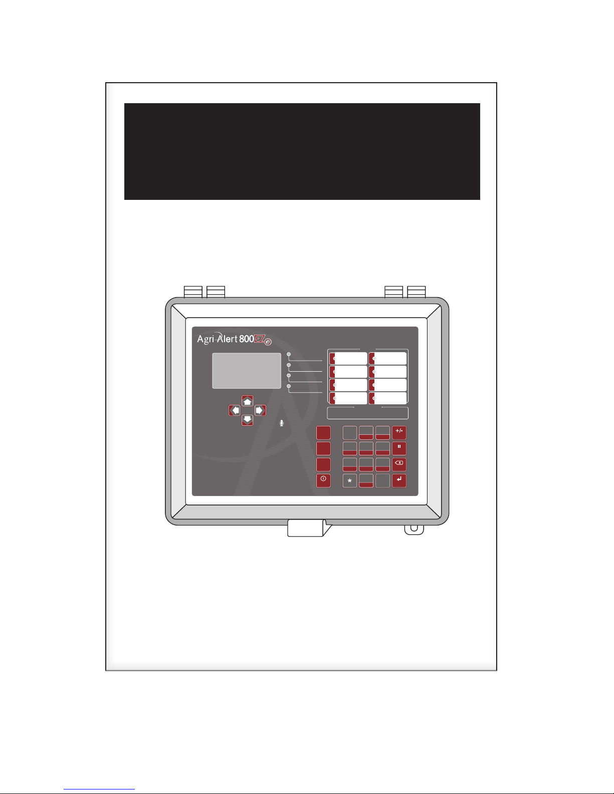
Agri-Alert 800EZe
Alarm
System in Standby
Burglary Armed
Online (phone)
ZONES
1
2
3
5
6
7
8
Main
Menu
Alarm
Memory
Arm /
Disarm
Standby
4
GHI
7
PRS
1
2
ABC
5
JKL
8
TUV
0
QZ
3
DEF
6
MNO
#
9
WXY
Back
Enter
Pause
AM / PM
ZONE LIGHTS LEGEND
4
Green = zone activated
Amber
=
zone bypassed
Red
=
zone in alarm
Off
=
zone deactivated
Alarm System
User’s Manual
Read this guide carefully before using the alarm system.
Page 2

AA800EZe
Manufacturer:
Viatron Electronics
5200, Armand-Frappier
Saint- Hubert (Qc)
Canada
J3Z 1G5
WARNINGS
The warranty can be void if this product is used in a manner
not specified by the manufacturer.
Every effort has been made to ensure that this manual is
complete, accurate and up-to-date. The information contained in it is however subject to change without notice
due to further developments.
2
AA800EZe rev.03
Page 3

AA800EZe
TABLE OF CONTENTS
1. INSTALLATION ....................................................4
1.1. Precautions .....................................................4
1.1.1. Precautions, Care & Maintenance ................. 4
1.1.2. Symbols of the Manual ...............................4
1.2. Installation Procedure .......................................4
1.3. Mounting the Equipment ...................................4
1.4. Connecting the Equipment .................................5
1.4.1. Sensors ...................................................5
1.4.2. AC Power Connection ................................ 5
1.4.3. Backup Battery Connection ......................... 5
1.4.4. Siren Output ............................................. 5
1.4.5. 12VDC Output ........................................... 5
1.4.6. Outdoor Temperature Sensor ....................... 6
1.4.7. Relays ......................................................6
1.4.8. Phone Hookup ........................................... 6
1.4.9. Connecting the Earth Ground ....................... 6
2. USER INTERFACE .................................................7
2.1. Front Panel ......................................................7
2.2. Modifying a Parameter ......................................7
2.3. Navigation .......................................................7
2.4. Acknowledging an Alarm ..................................8
2.5. Telephone Interface ..........................................8
2.5.1. Alarm Report Call ....................................... 8
2.5.2. Status Report over the Phone ..................... 8
3. SYSTEM INITIALIZATION ....................................10
3.1. Installation Wizard ..........................................10
3.2. Password ..................................................... 10
3.2.1. Setting the Passwords .............................. 10
3.2.2. Changing the User Level ........................... 11
3.3. Time & Date ..................................................11
3.4. Units of Measurement .....................................11
3.5. Siren ............................................................11
3.6. Speakers .......................................................12
3.7. Configuring the Zones .....................................12
3.7.1. Introduction ............................................. 12
3.7.2. Number of Zones & Outside T° Sensor ....... 12
3.7.3. Dry Contact Inputs & Burglar Zone Settings . 13
3.7.4. Temperature Zone Settings........................ 14
3.7.5. Assigning a Relay to a Zone ...................... 14
3.7.6. Disable the Siren ...................................... 15
3.7.7. Zones’ Vocal Identification ........................ 15
3.7.8. Initial Activation of the Zones .................... 15
3.8. System Setup ................................................16
3.8.1. Standby Mode ......................................... 16
3.8.2. System’s Vocal Identification ..................... 16
3.8.3. High Noise Alarms .................................... 16
3.8.4. Relay Status ............................................ 17
3.8.5. System Self Test...................................... 17
3.8.6. System Alarm Monitoring .......................... 17
3.8.7. Software Version ..................................... 17
4. COMMUNICATION PARAMETERS ........................18
4.1. Introduction ................................................... 18
4.2. Dialout Sequence ...........................................18
4.3. Dialing Information .........................................19
4.4. Phone Numbers ..............................................20
4.5. Pager Setup ...................................................20
4.6. On-Site Listening ............................................21
4.7. Phone Call-in .................................................21
4.8. Disable the Dialer ...........................................22
4.9. Test Report ................................................... 22
5. ALARM PARAMETERS ........................................23
5.1. Summary of Events ........................................23
5.2. Internal System Alarms ...................................23
5.3. Outdoor Temperature Compensation .................23
5.4. Burglar Zones ................................................24
5.4.1. Entry/Exit Delays ...................................... 24
5.4.2. Arming/Disarming the System .................... 24
5.5. Zone Status ...................................................25
5.5.1. Bypass / Activate ..................................... 25
5.5.2. View/ Modify Zone Settings ...................... 25
6. MONITORING FUNCTIONS ..................................26
6.1. Alarm Memory ...............................................26
6.2. Current Conditions .........................................26
6.3. Event Buffer ..................................................26
7. INSTALLATION CHECK LIST ................................26
8. UPDATE / BACKUP .............................................27
9. TECHNICAL SPECIFICATIONS ..............................28
10. TROUBLESHOOTING GUIDE .................................28
10.1. System Troubles ............................................28
10.2. Memory Card Troubles .................................... 29
10.3. Phone Communication Troubles .......................29
11. APPENDIX .........................................................29
11.1. Wire Length ...................................................29
11.2. Backup Battery Life Span ................................ 29
12. INDEX ...............................................................30
AA800EZe rev.03
3
Page 4
AA800EZe
INSTALLATION1.
Precautions1.1.
Precautions, Care & Mainte-1.1.1.
nance
WARNING: Read and save
these instructions!
Safety may be jeopardized if the equipment is
used in a manner not specified by the manufacturer. Carefully read and keep the following
instructions for future reference.
The room temperature where the alarm system is located must always remain between
32°F and 104°F (0°C to 40°C). For Indoor
use only !
To avoid exposing the alarm system to harmful gases or excessive humidity, it is preferable to install it in a corridor.
Do not spray water on the alarm system ! In
order to clean it, wipe it with a damp cloth.
Th e encl o s u r e shou l d be open e d an d insp e c ted once a year for moisture. Proper care will
extend the life of the system.
For Customer Use: Enter b elow the serial
numbe r loc ated on the side of the alarm
system and keep this information for future
reference.
Symbols of the Manual1.1.2.
Warning. Read the following text carefully; it contains important information
which, if ignored, may cause the
controller to operate improperly.
High Voltage. Hazard of electrical
shock. Read the message and follow
the instructions carefully.
Pay attention. The following text
contains very useful information.
Double insulation.
Both direct and alternating current
(AC/DC).
Direct current (DC).
Alternating current (AC).
Earth Ground Terminal
Primarily used for functional earth
terminals which are generally associated with test and measurement
circuits. These terminals are not for
safety earthing purposes but provide
an earth reference point.
1.2. Installation Procedure
To avoid electrical shocks and equipment
damage, unplug the unit before making
connections.
Determine where you want to install the 1.
system. You need an unswitched AC power
outlet and a telephone plug nearby to operate the system.
Make a list of all the sensor inputs you will 2.
be using with the Agri-Alert system.
Mount the Agri-Alert system on the wall 3.
(see section 1.3).
Connect a ground wire to the ground ter-4.
minal of the system (see section 1.4.9).
Install and connect all zone sensors and 5.
the siren. If the alarm system uses the phone,
connect the phone line to the Phone Plug-in
Card and then insert the card in the PHONE
CARD port of the Agri-Alert. If the system
uses an outside temperature sensor, connect
the sensor to the Outdoor Plug-in Card and
then insert the card in the OUTDOOR port
of the Agri-Alert. These 2 plug-in cards are
optional (see section 1.4).
Install the battery and then power up the 6.
Agri-Alert with the 16VAC wall transformer
(note that the system will not boot when
connecting the battery).
Mounting the Equipment1.3.
Model: AA800EZe
Serial number:
Date installed:
4
AA800EZe rev.03
The Agri-Alert system should be mounted
on a wall. Use 3/16” diameter screws to
mount the enclosure on the wall. Fasten the
black caps onto the mounting holes once the
screws are tightened. Make sure the cover
can be opened easily (to open the enclosure,
pull the latch and lift the cover).
If outdoor connections are used, mount
the enclosure as close as possible to the
entry point of the outdoor wiring.
Page 5
AA800EZe
1.4. Connecting the Equipment
Electrical knockouts are located on the bottom of the enclosure for running the cables.
Use a screwdriver and a hammer to punch
out the holes. Additional holes made in the
enclosure will void the warranty.
Strip the wires as little as possible (about
1/4”) to avoid electrical shor ts. Once they
are connected, run them through water tight
nyl on cable glan ds at the bottom of t he
enclosure.
All wiring must be done by an authorized electrician and must comply with
applicable codes, laws and regulations.
Be sure power is off before doing any
wiring to avoid electrical shocks and
equipment damage.
Do not install rigid conduit into electrical
knockouts. Only nylon cable glands are
permitted for cable or wire fastening.
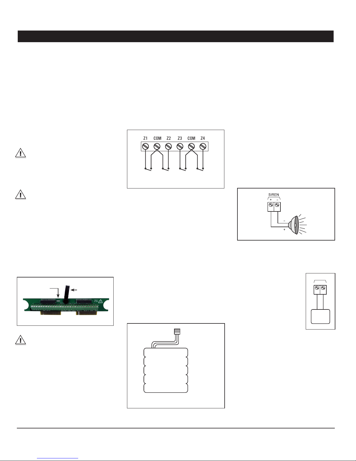
Removable Circuit Card : The terminal blocks
of the Agri -Alert are mounted on a removable
card. Removing the card from the bottom
board makes the system easier to connect.
In order to take it out from bottom board,
gently pull upward on the plastic loop; to
put the card back in place, align the metallic
guide of the bottom board with the hole in
the terminal card and then push the circuit
card all the way down.
Hole to align the
metallic guide
Before making the connections, pass the
wires through an hermetic cable holders
at the bottom of the enclosure.
Plastic loop
1.4.1. Sensors
The terminals used for senso r inputs are
numbered Z1, Z2, Z3, etc. on the removable
card. Connect each sensor to a Z terminal and
to the ground terminal (COM). Note that each
“COM” terminal is used by two zones; for
example, Z1 and Z2 share the same “COM”
terminal. Make sure each sensor is connected
to the proper “COM” terminal. False alarms
can result if the ground wires are not properly
connected.
Zone 1
Sensor
Zone 2
Sensor
Zone 3
Sensor
Zone 4
Sensor
1.4.2. AC Power Connection
The terminals marked 16VAC on the main
board are used for connecting the transformer. The transformer provided with the system
is a 16.5VAC/40VA transformer. It must be
plugged into a 120VAC 50/60Hz outlet. Make
sure the power source is unswi tched (i.e.
there is no switch on the power outlet).
1.4.3. Backup Battery Connection
The Agri-Alert system uses a rechargeable
8.4V battery Ni- MH 2300 mAh (part number
112-0 0007). No other type of battery can be
used. Plug the battery pack’s male connector to the female socket located on the main
board inside the enclosure. See Appendix B
for normal battery life spans.
Battery Connector
Battery Pack
1.4.4. Siren Output
Connect the siren to the SIREN terminals on
the removable circuit card. The voltage sup plied is 12VDC with a maximum current of
1A. Note that the battery must be hooked up
if a siren is used.
Make sure the positive wire is connected to
the positive terminal of the siren. The siren
circuit is monitored by the Agri-Alert system
for defects and wire troubles. This may not
work properly if the impedance of the siren
is too high. If this is the case, you can add a
1.5KOhm resistor (1/2W) to the siren circuit
as close to the siren as possible.
If no siren is used, connect a 1.5KOhm 1/2W
re sis to r b e tween th e po si tiv e a nd neg ati ve te rmi n als o f t h e si ren o r di s abl e the sire n mo n i to ring function as explained in section 3.5.
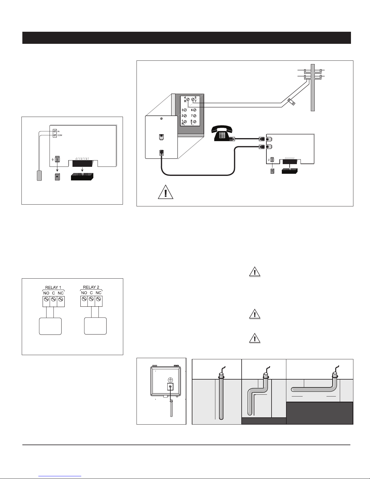
1.4.5. 12VDC Output
The terminals marked 12VDC
provide 12VDC with a maxi mum current of 500mA. This
output can be used to power
othe r accessori es such as
temperature controllers or the
Agr i- Al er t wireles s module
(WM-3000). In case of power
failure, the battery back-up
provides 12VDC to this line.
12VDC
+
+
12 VDC
Device
-
-
AA800EZe rev.03
5
Page 6
AA800EZe
1.4.6. Outdoor Temperature Sensor
In order to use an outside temperature sensor a plug-in card must be inserted in the
“Outdoor” port of the Agri-Alert (be sure
to line up the ground connector of the card
with the quick connect pin of the bottom
board). The outdoor temperature plug-in card
is optional.
Outdoor Card
Ground
Connector
temperature
sensor
Quick
connect
Pin
“OUTDOOR” portOutside
1.4.7. Relays
The Agri-Alert has 2 built-in relays which can
be used to control various on/off devices.
Relay outputs provide 24VDC or AC with a
maximum current of 2A. They can either be
activated manually or when an alarm occurs
in a zone.
N.O.
On/Off
Device
Normally
Open (N.O.)
Connection
N.C.
On/Off
Device
Normally
Close(N.C.)
Connection
Phone Hookup
*The TIP wire is the one with the
most positive voltage reading on a
voltmeter.
Tip*
Ring
CAUTION – To reduce the risk of fire, use only No. 26 AWG or
larger telecommunication line cord.
If dialing functions are used, the system has
priority over other users when dialing out.
This means the system disconnects all other
phones on the line when dialing out in case
of emergency.
1.4.9. Connecting the Earth Ground
The earth ground terminal of the Agri-Alert must
be connected to the earth ground as follows.
Use a rod at least 5/8 inches (16 millimeters)
in dia meter at least 10 feet (3 meter) long.
The rod must have a clean metal surface
free of paint, enamel or other nonconducting
substances. Drive the rod at least 10 feet
(3 meters) into the ground. If the bedrock is
more than 47 inches (1.2 meters) deep, drive
the rod into the ground to bedrock level and
bury any remainder horizontally at least 2 feet
(600 millimeters) below ground level. If the
bedrock is less than 47 inches (1.2 meters)
deep, bury the rod horizontally at least 2 feet
Phone Card
Phone line OUT
Phone line IN
Ground
connector
Quick
connect pin
Phone card connector
(600 millimeters) below groun d level (ref.
Article 10-702, 3d of the Canadian Electricity
Code C22.10 -99).
The rod must be connected to the wire described above. It is recommended to let the rod
going out of the ground to connect it. The wire
length must not exceed 50 feet (15 meters).
IMPORTANT: The earth ground terminal
must be connected to a proper ground
to protect the electronic components
from damage due to lightning surges and
electrostatic discharges. Do not use the
electrical ground for this purpose
If outdoor connections are used, mount
the enclosure as close as possible to the
entry point of the outdoor wiring
A faulty earth ground connection immediately voids the system warranty
without further notice.
1.4.8. Phone Hookup
A plug-in card must be inserted in the “Phone
Card” port of the Agri-Aler t to use dialing
functions (be sure to line up the ground connector of the card with the quick connect
pin of the bottom board). The phone plug-in
card is optional.
6
AA800EZe rev.03
10ft (3m)
metal rod
EARTH
2 ft
(600mm)
10ft
10ft (3 m)
(3 m)
<47 in( 1.2 m)
2 ft
(600mm)
10ft (3 m)
Bedrock
<47 in( 1.2 m)
Page 7
AA800EZe
USER INTERFACE2.
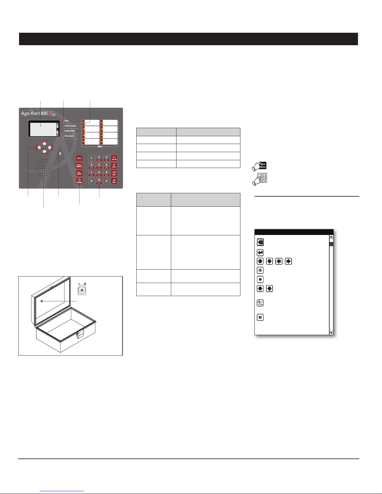
2.1. Front Panel
LCD Screen
Arrow keys Microphone
Speaker
Graphic LCD Screen: A graphic LCD screen is
used to provide and collect information. The
contrast of this screen can be adjusted with
the potentiometer located behind the display.
Turn the potentiometer with a screwdriver to
adjust the contrast of the screen.
Status LEDs Zone Status LEDs
Keypad
Short-cut
keys
Potentiometer of the
LCD screen
Keypad: The keypad is used to enter data
and to enable/disable the various functions
of the system.
Hot Keys: The hot keys bring you to specific
pre- defined menus. These menus are not accessible from the main menu.
Zone Status LE Ds:
Zone LED Meaning
Red Zone is in alarm
Green Zone is activated
Amber Zone is bypassed
Off Zone is disabled
System LEDs:
System Status
LED
Alarm This LED is On when one or
System in
Standby
Burglary
Armed
Phone This LED is ON when the sys-
Meaning
more alarm conditions are detected (the individual zone LED
on the right side of the panel
tells which zone is in alarm).
This LED is ON when the
Agri-Alert system is in standby
mode (the system does not
monitor alarm conditions). It
turns OFF when normal monitoring is resumed.
This LED is ON when the
burglar zone is armed.
tem uses the phone line.
Modifying a Parameter2.2.
Use the numeric keypad and/or the up and
down arrow keys to modify the value of a
parameter and then press Enter to validate
the new value.
2.3. Navigation
Menus items can be accessed with the arrow keys or by pressing the proper number
on the numeric keypad. A highlight bar indicates which item is selected on screen. You
can move this bar up and down using the
arrow keys and then press “Enter” to select
the menu item. Press “Back” to exit from a
menu.
To get further information about the naviga tion process, select the help menu:
Select:1.
• Main Menu
• Help Menus
• Programming Notes
The system gives the meaning of all possible
navigation icons:
Program ming Notes
Previous Screen/
Cancel Editing
Enter/Select/Apply
N a v i g at e
Exit Wizard
Next wizard Step
Increase /
Decrease Value
Negative Sig n/Switch
time to PM
Insert Pause in Phone
Number
Arrow Keys: These keys are used to step
through menu items.
Speaker: The speaker delivers the system
identification and alarm messages.
Integrated Microphone: The microphone is
used to record ID messages and gives an
on-site listening input.
A password may be required to change the
value of a parameter. Refer to section 3.2.2
to enter/change your password or to disable
the protected access.
AA800EZe rev.03
7
Page 8
AA800EZe
2.4. Acknowledging an
Alarm
The Agri-Alert knows an alarm message has
been received when a user acknowledges the
alarm. There are several ways of doing this. If
you are on -site when an alarm is detected, enter your password (if the password feature is
enabled) or simply press <1> key on the front
panel to acknowledge the alarm. You can also
acknowledge an alarm over the phone when
the Agri-Alert system reports the alarm or
you can call the Agri-Alert system yourself
between phone dialouts if the intercall time
is greater than zero (see section 2.5).
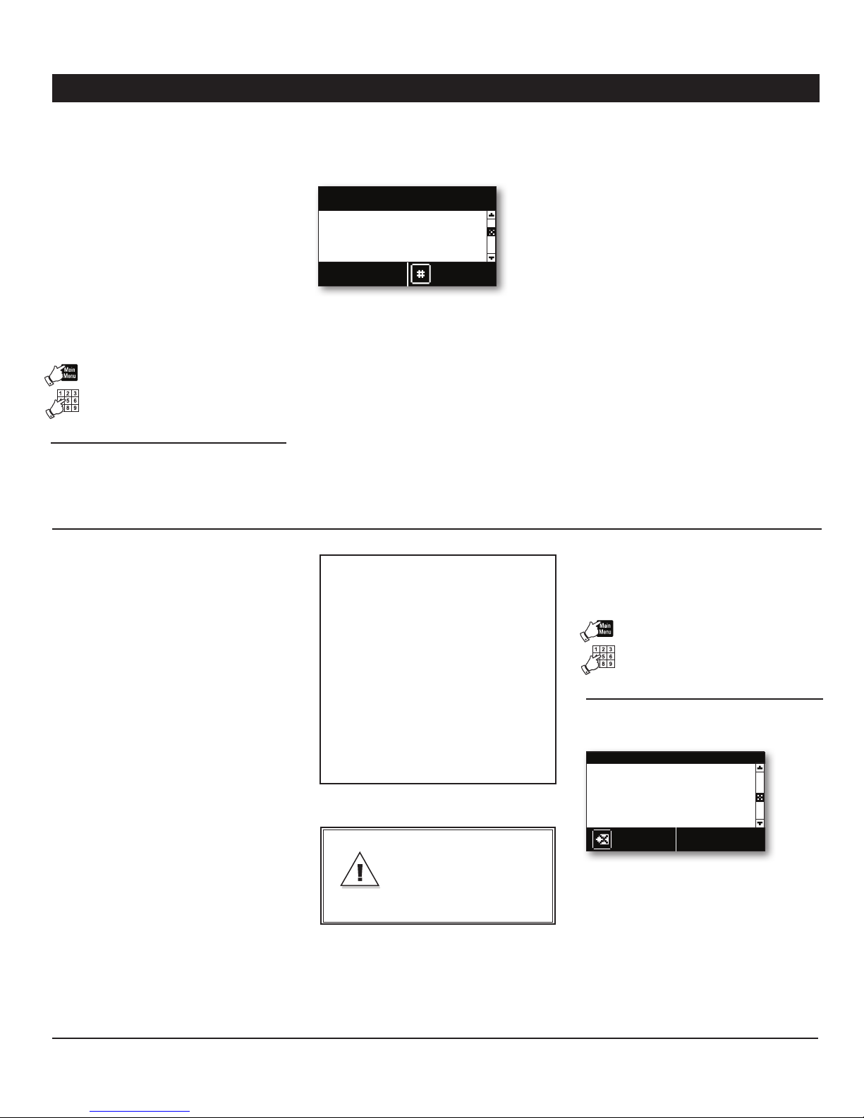
Follow this seq uence to ack nowledge an
alarm from the keyboard:
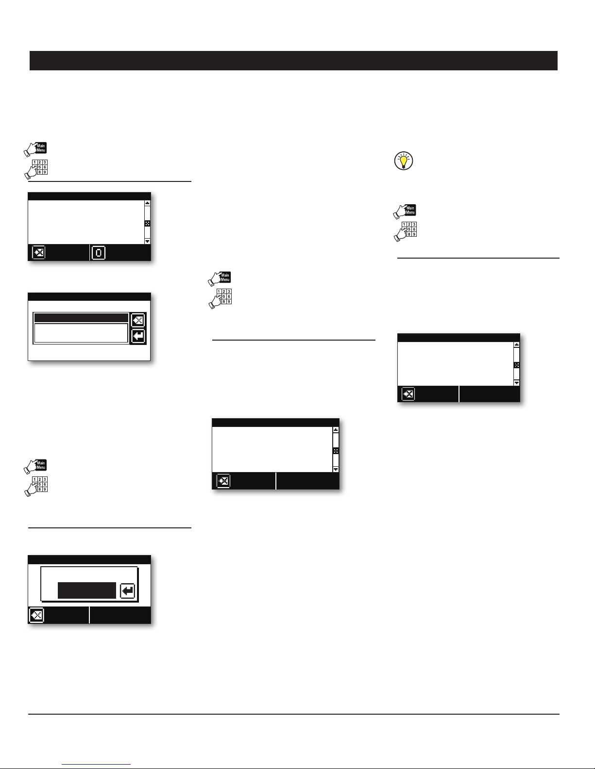
If this screen is not already displayed, 1.
press the Alarm Memory but ton.
System is in alarm
Curtain doesn't move
Press 1 to continue
to acknowledge alarm
Continue
Press 1 to continue. 2.
If you have not been identified by the 3.
system yet, the Agri-Alert may prompt for a
password. Type in your password and then
press Enter.
Active Alarm Status
Alarm Mem ory
System is in Alarm
Press 1 to Acknowledge
Continue
Press 4. “#” to get details about the active
alarm situation or type 1 to acknowledge it
right away. Note that the dialout sequence
automatically star ts when an alarm is set
off (if the zone in alarm uses the dialout
function).
View
Memory
Telephone Interface2.5.
The Agri-Alert system sends alarm reports
over the phone. You can also call the system
to get some status reports. When calling the
Agri-Alert, make sure the “Phone Call-in” parameters are set properly (see section 4.7).
2.5.1. Alarm Report Call
When an alarm occurs, the Agri-Alert system
tries to reach you by phone and dials all numbers of the dialout sequence (see chapter 4).
It puts an end to the dialout sequence when
the alarm is acknowledged.
The following section outlines the dialog session when a number is reached. Note that a
touch-tone phone is required to respond to
the system prompts and that the sys tem
automatically hangs up whe n the session
is over.
2.5.2. Status Report over the
Phone
You can dial into the Agri-Alert system and
obtain status reports over the pho ne. A
touch -tone phone is needed to respond to
the system prompts.
The following section outlines the dialogue
session when the Agri-Alert system answers
the call. The system automatically hangs up
when the status repor t is finished.
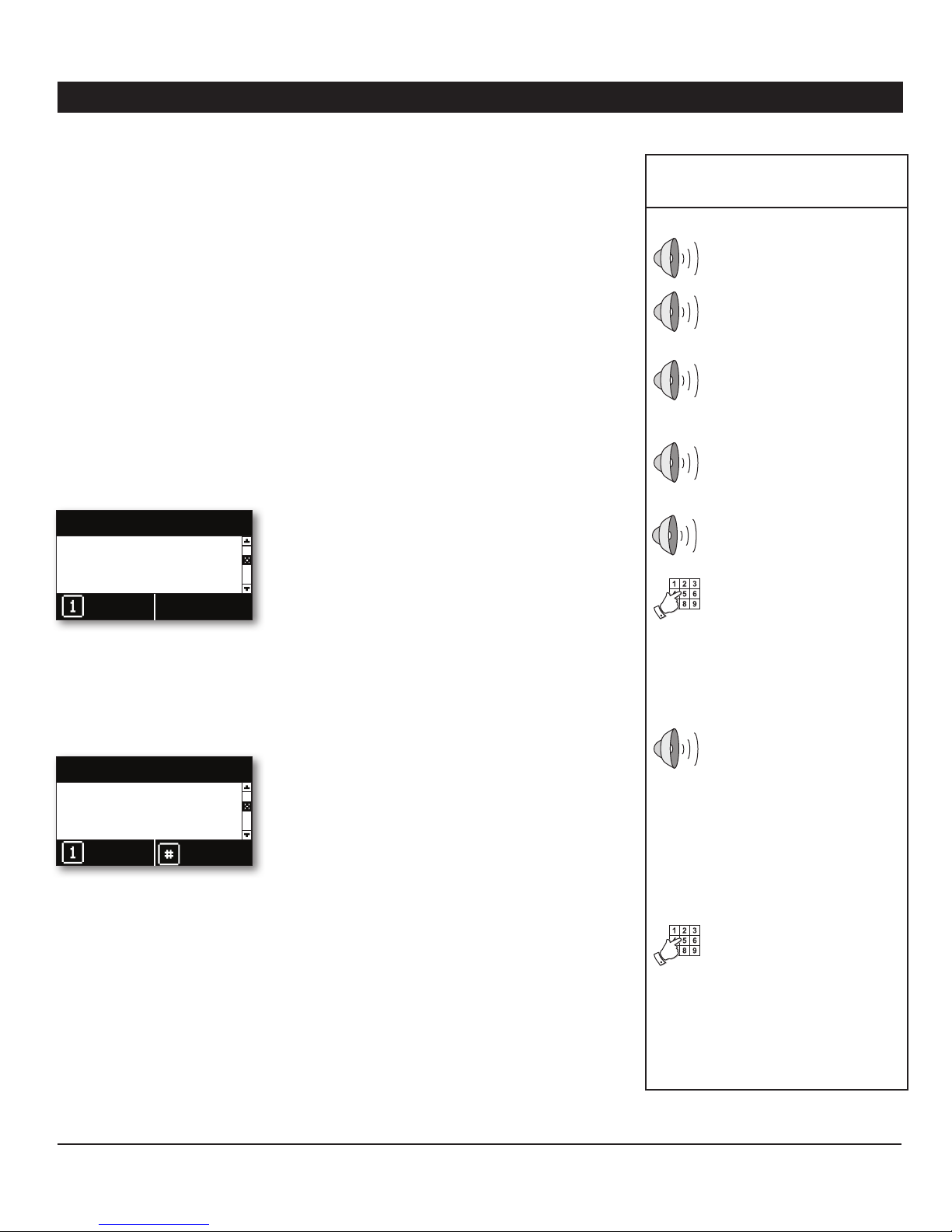
Telephone Session –
Alarm Call
Hello, this is Agri-Alert
ID message of the Agri- Al er t
system (if applicable)
Description of the alarm condition
(e.g.: “Alarm Zone 1”).
On-site Listening
[Microphone input is sent over
the phone for on-site listening
if enabled].
To acknowledge the alarm message, enter your password and
press Star (*)
Th e user enters a fou r- di gi t p a s s word on the phone keypad and
presses start (*). If an incorrect
password is entered, the system
replies “Wrong password”; if it
is corre ct, the system replie s
“OK”. The system automatically
acknowledges the alarm when a
correct password is entered.
Main Menu:
- For a complete status report,
press 1;
- For a status report on a particular zone, press 2;
- To select relay, press 3;
- For on-site listening, press 4;
- To ac t ivate / by p ass a zon e,
press 5;
- For a new selection, press 8;
- To hang-up, press 0.
Th e use r selec ts th e desired
menu on the keyboard.
The siren stops ringing when the alarm is
acknowledged. If the alarm is not acknowledged at the end of the dialout sequence, the
Agri-Alert automatically acknowledges it and
stops the siren.
8
AA800EZe rev.03
Page 9
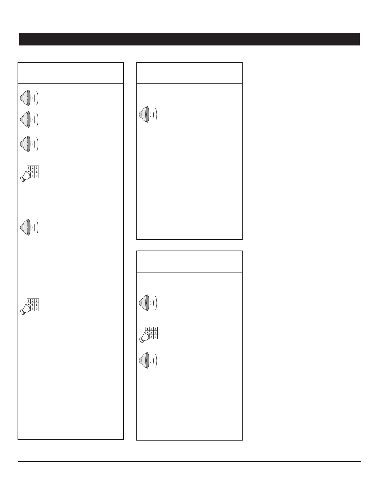
AA800EZe
Telephone Session
Status Report
Hello, this is Agri-Alert
ID message of the Agri- Al er t
system (if applicable)
Enter your password and press
star (*)
Th e user enters a fou r- di gi t p a s s word on the phone keypad and
presses start (*). If an incorrect
password is entered, the system
replies “Wrong password”; if it
is corre ct, the system replie s
“OK”.
Main Menu:
- For a complete status report,
press 1;
- For a status report on a particular zone, press 2;
- To select relay, press 3;
- For on-site listening, press 4;
- To ac t ivate / by p ass a zon e,
press 5;
- For a new selection, press 8;
- To hang-up, press 0.
Complete Status Report
[...]
Status of each zone:
- Activated;
- Bypassed;
- Deactivated;
- Not installed;
- Alarm (if the zone is in alarm);
- Tempera tu re (if this is a T°
zone).
Status of the system:
- Low battery / Bat tery OK;
- System power down / System
power OK;
- System trouble;
- Relay 1-2 ac tivated / deactivated.
[System retur ns to the main
menu]
Zone Status Report
[...]
Th e use r selec ts th e desired
menu on the keyboard.
Enter zone number and press
star (*).
Th e user ty p e s in the z on e n u m -
ber on the keypad and presses
star (*).
Status of the chosen zone:
- Activated;
- Bypassed;
- Deactivated;
- Not installed;
- Alarm (if the zone is in alarm);
- Tempera tu re (if this is a T°
zone).
[System retur ns to the main
menu]
AA800EZe rev.03
9
Page 10
AA800EZe
SYSTEM INITIALIZATION3.
3.1. Installation Wizard
The Installation Wizard guides you through
the pro ce s s o f in i t i a l i zin g yo ur A g r i - A l e r t s ys tem. When it is launched, the Wizard displays
all setup menus in turn. You can choose to
perform or to skip each programming step
and can exit from the Wizard at any time.
To run the Installation Wizard:
Select:1.
• Main Menu
• Install Programming*
• Use Program Wizard
* Accessible with the Installer or Master password
only (see section 3.2).
3.2. Password
The Agri-Alert can use a password protection
to l im i t a c c e s s to cer t a i n me n u s an d can iden tify 4 different levels of users (the password
protection is optional):
LEVEL 1– System:
This user level is automatically selected after
5 minutes of inactivity. It gives a read- only
access to the current condition menu and to
the system version menu.
LEVEL 2 – User:
This user level gives access to all functions of
the controller except for the “Install Program-
ming” menu. Up to 8 different password can
be assigned to the users.
LEVEL 3 – Installer:
This user level gives a read/write access to
all functions of the system, except for the
event buffer .
LEVEL 4 – Master:
This user level gives a read/write access to all
functions of the system, including the event
buffer menu.
Welcome to Wizard
Insta llation
1 Set Time & Date
2 System Options
3 Install Zone
4 Install Phone
Start
All programming steps are displayed. 2.
Press the pound key “#” to launch the 3.
Installation Wizard or press Back to cancel.
Follow the prompt s to confi gu re your 4.
Agri-Alert system.
Programming steps — Here is a list of all
programming steps of the Installation Wizard.
Refer to the proper section of this manual to
get information about each of them.
Default Passwords:
Master 0800
Installer 0801
User 1 1111
User 2 2222
User 3 3333
User 4 444 4
User 5 5555
User 6 6666
User 7 7777
User 8 8888
IMPORTANT
Choose easy-to-remember
passwords and write them
down in a safe place!
• Time and date (section 3.3)
• System options
Units of measurement (section 3.4)
Speaker volume (section 3.6)
Passwords (section 3.2)
• Setup Zones (section 3.7)
• Outdoor Temp. compensation (sec. 5.3)*
* Accessible if a zone uses the outside temperature
sensor (sec. 3.7).
• Phone numbers (sections 4.3 & 4.4)
• Burglar arming options (section 5.4)
• Siren options (section 3.5)
Setting the Passwords3.2.1.
Select:1.
• Main Menu
• System Auxiliaries
• Password Management*
* Accessible with the Installer or Master password
only (see section 3.2).
Password Managem ent
Current User Installer
Enable password Yes
Installer 0801
User 1 1111
User 2 2222
Back
Set the following parameters:2.
Enable password — Select “Ye s” to use the
password protection or select “ No” to disable it.
10
AA800EZe rev.03
Users — Use the numeric keypad to specify
the password of each users.
Page 11
AA800EZe
3.2.2. Changing the User Level
Select:1.
• Main Menu
• System Auxiliaries
System Auxiliaries
1 Update/Backup
2 Password Managem ent
...
Back
Press ”0” to change the user level in use.2.
System Auxiliaries
Enter your Password
Enter the password of the desired user.3.
Change
User
Set the following parameters:3.
Use the arrow key and/or the numeric keypad to
change the value of the pa rameter displayed on
screen. When it is set, press Enter to validate the new
value and to step to the next parameter.
Month, Day & Year;
Ti m e of d ay — Use t he n u m e r i c keypad t o e n -
ter the time of day. If required, press the AM/
PM but ton to change the AM/PM status.
3.4. Units of Measurement
Select:1.
• Main Menu
• System Auxiliaries
• User Preferences
• Units
Use the arrow keys to select the desired parameter on screen and then, use the arrow
keys and/or the numeric keypad to change its
value. When the parameter is set, press Enter
to validate the new value.
3.5. Siren
The system activates the siren output when
an alarm is set off. The procedure below allows the Agri-Alert to use the siren output.
It is possible to disable the siren output
in specific zones (see sec. 3.7.6).
Select:1.
• Main Menu
• View/Modify
• Siren Settings
Use the a rrow keys to sele ct the desired
parameter on screen and then use the arrow
keys and/or the numeric keypad to change
its value. When the parameter is set, press
Enter to validate the new value.
Sire n
Monitoring
Yes
Start Delay 0:00(m:s)
Time On 0:00(m:s)
Back
3.3. Time & Date
Select:1.
• Main Menu
• System Auxiliaries
• User Preferences
• Time and Date
Time and Date
Wed Oct 14 2008
11:59:00 A M
Back
Press Enter to start editing the time and 2.
date.
Temp. Format °F
Unit Preferences
Time Format AM/PM
Date Form at D/M/Y
Back
Set the following parameters:2.
Temperature Units — Celsius (°C) or Fahrenheit (°F).
Time Format — AM/PM or 24-hour.
Date Format — Select the proper date format
(Year/ Month/ Day).
Set the following parameters:2.
Monitoring — Select “N o” if no siren is con-
nected to the siren output. This way, the
Agri-Alert will never send a “defective alarm”
error. By default, the siren’s monitoring feature is enabled.
Start Delay — This para meter is used to
postpone the moment at which the Agri-Alert
activates the siren when an alarm is detected.
It ranges from 0 to 15 minutes. The default
is 0 minute.
Time ON — When an alarm is declared, the
siren sounds during this length of time. It
ranges from 1 to 15 minutes and is set to
5 minutes by default.
AA800EZe rev.03
11
Page 12

AA800EZe
3.6. Speakers
Whe n an ala rm condition is validated, an
al ar m mes sage is im me diate ly de li ve red
through the unit speaker. You can adjust the
volume of the system’s voice and can turn the
speaker on or off. By default, the mute function is disabled and the speaker enabled.
Select:1.
• Main Menu
• System Auxiliaries
• User Preferences
• Voice Volume
Voice Volum e
Speaker Volume 50
Mute Voice No
Back
Set the following parameters:2.
Speaker Volume — Set the speaker volume
to the desired intensity.
3.7. Configuring the Zones
Introduction3.7.1.
The Agri-Alert system is a device used to detect alarm conditions. It can monitor several
types of sensors and can launch a dialout
sequence each time an alarm is detected on
one of its inputs.
When an alarm is detected, the system re ports the alarm on-site and starts the dialout
sequence. It maintains the alarm active up
until a user acknowledges it, either on- site
or on the phone. In addition, the Agri-Alert
stores all relev an t info rm at io n regarding
the incident: the zone number, the type of
alarm, the moment at which it occurred/was
acknowledged and the identity of the user
who has acknowledged it.
Zone Definition:
A zone is an input configured to respond to
the type of sensor connected to it. In all, the
Agri-Alert can monitor 8 different zones on
which dry contact, dry contact burglar, or
temperature sensors can be connected.
Note that when you reconfigure a zone,
the system automatically deactivates
this zone input. Refer to section 3.7.8
to reactivate it.
3.7.2. Number of Zones & Outside
T° Sensor
The Agri-Alert can monitor up to 8 different
zone inputs and 1 outside temperature sensor. This section explains how to activate
these inputs.
Select:1.
• Main Menu
• Install Programming*
• Program Zones
* Accessible with the Installer or Master password
only (see section 3.2).
Zone Installation
How many zones ? 8
Use Outdoor T° No
Back
Set the following parameters:2.
How m an y zones ? — Select how many zones
are required (from 1 to 8 zones).
Mute Voice — Select “Yes” to mute the sys-
tem’s voice or select “No” to allow spoken
message to be delivered through the speaker.
If an alarm situation occurs while the voice is
mute, the system sends out an alarm sound
instead of a vocal message.
Use Outdoor Temperature Sensor ? — Select
“Ye s” i f an outside te mp e r a t u re sensor is c on nected to the Agri-Alert.
12
AA800EZe rev.03
Page 13

AA800EZe
3.7.3. Dry Contact Inputs & Burglar Zone Settings
Dry contacts can be either normally open
(NO) or normally closed (NC) circuits. In addition, they can be configured for an end of
line resistor (EOLR). Adding an end of line
resistor will help the system detect wiring
problems. This is illustrated in the figure below. In the center diagram, an open wire has
occurred. The system detects this by reading
the resistance on the circuit and sets off an
alarm when this happens. The figures below
shows three possible states for a normally
open circuit with EOLR.
Normally Open Circuits
with EOLR
Normal Alarm Alarm
opened circuit
The following figures show different zone
connection examples. Note that if you add
an EOLR to a circuit, the resistor must be
connected to the sensor that is furthest from
the Agri -Alert system.
Dry Contact Burglar Input
Dr y conta ct inputs can be confi gu red as
burglar zones. The se zones are armed or
disarmed as a group using a password and
they are connected just as regular dry contact
inputs. Burglar zones can be configured in
2 different ways:
Examples of Zone Connections
without EOLR
Normally open circuit Normally closed circuit
Examples of Zone Connections
with EOLR
Normally open circuit Normally closed circuit
Instant burglar zone: in this type of zone, 1.
alarms are decla re d as soon as they are
detected.
Delayed burglar zone: in this type of zone, 2.
alarms are declared only after an entry delay
has elapsed. This way, the authorized user
has time to disarm burglar zones before an
alarm is declared (the delay is common to all
delayed burglar zones). Similarly, all zones are
armed after the exit delay has elapsed.
When the system is arming, the speaker starts
beeping and the Agri-Aler t displays a countdown of the exit delay. After the exit delay
has elapsed, the “Burglary Armed” pilot light
turns red, the system arms all burglar zones
and sets off an alarm as soon as an alarm
situation occurs in any burglar zone.
If an alarm occurs in a burglar zone with an
entry delay, the Agri-Alert displays a countdown of the entry delay. The speaker beeps
during this delay and stops beeping when
the key sequence is entered. If no one has
disarmed the system after the entry delay
has elapsed, an alarm is declared; if someone
has correctly disarmed the system, all burglar
zones are disarmed at once and the “Burglary
Armed” pilot light turns off.
Assigning Dry Contact & Burglar
Zones
Select:1.
• Main Menu
• Install Programming*
• Program Zones
* Accessible with the Installer or Master password
only (see section 3.2).
Press Next 2. to display a table showing
all zones in use.
Use the numer ic keypad to select the 3.
desired zone number.
Zone 1 Installation
Type Dry Contact
Normal State Closed
EOL Resistor No
Rec.Tim e (h:m :s) 0:00:30
Back
Set the following parameters:4.
Ty p e of Zone — Select “Dry Contact” to assign
a regular dry contact input ; select “Delayed
Burglar” to assign a dry contact burglar zone
which uses a delay or select “Instant Burglar”
to assign a dry contact burglar zone which
uses no delay.
Normal State (NO / NC) — Select the normal
state of the zone contact: Normally open or
normally closed contact.
Zone 2
EOL Resistor — Specify if the input has an
end of line resistor or not.
Recognition Time — Determine during how
much time t he a l a r m c o n d i t i o n m u s t b e main taine d before i t c o n s t i t u t e s a valid alarm s it u ation. *For regular dry contact inputs only.
Refer to section 5.4 to set the entry and
exit delays of burglar zones.
AA800EZe rev.03
13
Page 14

AA800EZe
3.7.4. Temperature Zone Settings
A tempera ture zone resp onds to change s
in temperature readings from a sensor. The
system sets off an alarm if the temperature of
a zone exceeds the user-defined temperature
range (the acceptable temperature range is
bounded between a low and a high temperature set point).
Assigning Temperature Zones
Select:1.
• Main Menu
• Install Programming*
• Program Zones
Room T°
Hi
Alarm
limit
Lo
Alarm
limit
alarm
sets off
Temperature Alarms
Type of Zone — Select “Tem p” to assign a
temperature zone.
Low / High Set Points — Set the lower and
upper values of the normal temperature range.
The low set point ranges from -60°F to 150°F
(-50°C to 65°C); the high set point ranges
from the low set point to 150°F (65°C).
Detecting
Legend
Room temperature
Alarm limits
Temperature alarm
No alarm
Time
3.7.5. Assigning a Relay to a Zone
The Agri-Alert has 2 relay outputs to activate
different devices when an alarm occurs in a
zone. This section shows how to assign a
relay to a zone.
Select:1.
* Accessible with the Installer or Master password
only (see section 3.2).
Press Next 2. to display a table showing
all zones in use.
Select Zone Numb er
Zone 1 Zone 2 Zone 3 Zone 4
Zone 5 Zone 6 Zone 7 Zone 8
Back
Enter
Use the numer ic keypad to select the 3.
desired zone number.
Zone 1 Installation
Typ e Temp
Low T° Set. 50.0°F
High T° Set. 90.0°F
Critical T° Set. 100.0°F
Rec.Time (h:m:s) 0:00:30
Back
Zone 2
Set the following parameters:4.
Critical Temperature — This is the absolute
temp erature limit for room temperatures.
It is used in conjunction with the outdoor
temperature compensation feature. When the
room temperature reaches this point and the
outdoor temperature compensation feature
is enab led, an alarm is set off, no matter
what the outdoor temperature is. The critical
temperature ranges from the high set point
to 150°F (65°C) with an accuracy of 0.1°F
(0.1°C). Enter the critical temperature and
press Enter. To enter a negative value, use the
“+/-” key. * Accessible if the outside temperature
sensor is enabled in section 3.7.2.
Recognition Time — Determine during how
mu ch time the al ar m con di tion mu st be
maintained before it constitutes a valid alarm
situation.
• Main Menu
• Install Programming*
• Program Auxiliaries
• Relay Assigned Zone
* Accessible with the Installer or Master password
only (see section 3.2).
Press the zone number on the keypad to 2.
change the relay assignment of that zone.
Relay Assigned Zone
1 2 3 4
Rel.1 --- --- ---
5 6 7 8
--- --- --- ---
Back
Mod ify
Select 3. “R el. 1” or “Rel.2” t o a s s i g n t h e 1st or
2nd relay to the selected zone; select “Non e”
if no relay is assigned to that zone.
14
AA800EZe rev.03
Page 15

AA800EZe
3.7.6. Disable the Siren
This function allows disabling the siren in
specific zones. By default, the siren is enabled
on all zones.
Select:1.
• Main Menu
• Install Programming*
• Program Auxiliaries
• Siren Enabled Zone
* Accessible with the Installer or Master password
only (see section 3.2).
Siren Enabled Zone
1 2 3 4
No Ye s Yes Yes
5 6 7 8
Yes Yes Yes Yes
Back
To change the siren status on a zone, 2.
simply press the zone number on the keypad.
Select “ Yes” to use the siren on the zone or
“N o” to disable it.
Mod ify
3.7.7. Zones’ Vocal Identification
When giving status repor ts and alarm messages, the system identifies the zones with
a voice recording provided by the user. This
section shows how to record these messages.
Select:1.
• Main Menu
• System Auxiliaries
• User Preferences
• Voice ID
• Zone Messages
Use the arrow keys to select the desired 2.
zone.
Zone 1 Message
Pla y
Record
Recording a New ID Message — To record
a new message, press star (*) and record
the ID message (8 seconds maximum). The
Agri-Alert then plays the new message over
the speaker.
Stop
Erase
3.7.8. Initial Activation of the Zones
This section explains how to activate the
zones when running the system for the
first time. If you want the Agri-Alert to
stop monitoring alarms in a zone afterwards, use the “Bypass Zone” function
instead of deactivating the zone (see
sec. 5.5.1).
After having been initialized, all zones are disabled. To start using them, you must activate
each zone as shown below (except for burglar
zones: this type of zone is automatically activated). The pilot light of a disabled zone is
off on faceplate of the controller.
Select:1.
• Main Menu
• Activate / Bypass
• Activate Zones
The zones that have been initialized are displayed on screen. Refer to section 3.7.1 to
create new zones.
Select Zone to Activate
1 2 3 4
No Ye s Yes Yes
5 6 7 8
Yes Yes Yes Yes
Back
Mod ify
Original ID Message — Press the pound key
“#” to retrieve the original ID message.
Press the zone number on the keypad 2.
to change the zone status. Select “Ye s” to
activate it.
AA800EZe rev.03
15
Page 16

AA800EZe
System Setup3.8.
3.8.1. Standby Mode
When it is in standby mode, the Agri-Alert
stops moni toring all a larm inpu ts and the
“System in Standby” LED turns on the front
panel. It also removes access to most of
its menus.
Select:1.
• Main Menu
• Press the Standby key
* Accessible with the Installer or Master password
only (see section 3.2).
Press Enter to select the desired system 2.
status.
Change system operating
mode
System is normal
Back
Use the arrow keys to select the normal 3.
mode or standby mode. Press Enter again
to validate.
3.8.2. System’s Vocal Identification
When giving status reports and alarm messages, the system identifies itself with a voice
recording provided by the user. This section
shows how to record this message.
Select:1.
• Main Menu
• System Auxiliaries
• User Preferences
• Voice ID
• System Message
System Message
Pla y
Record
Recording a New ID Message — To record
a new message, press star (*) and record
the ID message (8 seconds maximum). The
Agri-Alert then plays the new message over
the speaker.
Original I D Message — Press the pound key
“#” to retrieve the original ID message.
Stop
Erase
3.8.3. High Noise Alarms
The Agri-Aler t can trigger an alarm if the
level of noise around surrounding it gets too
high. High noise alarms can be used warn
you if a generator’s motor starts running for
instance.
In order to use high noise alarms, you must
calibrate the regular level of sound surrounding the A g ri - A l e r t a n d th e n sp e c i f y t h e recog nition time for this type of alarm.
Select:1.
• Main Menu
• View/Modify
• High Noise Alarm
High Noise Alarm
State Enabled
Rec.Tim e (h:m :s) 0:00:30
Start Calibration No
Back
Set the following parameters:2.
State — Select “Enable d” to use high noise
alarms or select “Disabled” to disable this
function.
Recognition Time — Determine during how
much time the alarm co ndition must be
maintained before it constitutes a valid alarm
situation.
16
AA800EZe rev.03
Start Calibration — Select “Yes” for the Agri-
Alert to record a sample of the regular sound
level surrounding it (this process takes about
10 seconds). Once the calibration is over, the
Agri-Alert star ts monitoring the level of sound
and triggers an alarm if it gets higher than the
sample sound for a period of time exceeding
the recognition time.
Page 17

AA800EZe
3.8.4. Relay Status
The Agri-Alert has 2 built-in relays which can
be used to control various on/off devices.
Relay can either be activated manually (i.e.,
the user activates or deactivates it manually)
or they can be activated only when an alarm
occurs in a zone. Note that it is not possible
to change the status of a relay that is associated with a zone.
Refer to section 3.7.5 to assign a relay
to a zone.
The following steps allow seeing the current status of the relays. Their status can be
change if they are not assigned to a zone.
Select:1.
• Main Menu
• View/Modify
• Output Relays
Relays
Relay 1 Activated
Relay 2 Deactivated
Back
The status of both relays is displayed. If a relay is not assigned to a zone, you can change
its status by pressing Enter and using the up
or down-arrow key.
3.8.5. System Self Test
The Agri-Alert system has the capability of
testing some of its functions. To start the
test, select the following menus:
Select:1.
• Main Menu
• System Self Test
Press 2. to launch the test.
System Self Test
No Self Test Running
Cancel
Outline of the test :
1. Test LEDs — The system makes each zone
LED go from red to green. It then turns on
each status pilot light in red.
2. Test LCD — The system tests the LCD
display. The LCD backlight is turned of f and
the display displays a rectangular pattern.
3. Test Siren — Two short beeps are sent to
the siren (if a siren is hooked up).
4. Test Relays — The Agri-Alert opens and
closes relays 1 and 2.
5. Test 12 VDC Output — The Agri-Alert
activates and then deactivates the 12VDC
output.
Start
System Alarm Monitoring3.8.6.
The Agri-Aler t generally launches the alarm
and the call sequence when it detects an
internal system failure. It is possible to disable the alarm monitoring for some of these
failures.
Select:1.
• Main Menu
• System Auxiliaries
• Monitoring
Monitoring
Bat ter y Yes
12Vd c Yes
16Vd c Yes
Line cut Yes
Sir en Yes
Back
Set the following parameters:2.
Battery / 12Vdc Output / 16Vac Supply / Line
cut / Siren — Select “No” if you do not want
the alarm to sound when one of these system
failure occurs.
3.8.7. Software Version
The following menu gives the actual version
of your Agri-Alert software.
Select:1.
• Main Menu
• System Auxiliaries
• Software Version
6. Audio (Record / Play) — The Agri-Alert
records surrounding sounds while the message “Record” is displayed. It then plays the
recorded sound through the speaker.
7. Dialout Sequence — The system launches
the dialout sequence.
800 EZe VX.X.XXXX
Jan 1 20XX
Base Mx Vx
AA800EZe rev.03
17
Page 18

AA800EZe
COMMUNICATION PA-4.
RAMETERS
Introduction4.1.
This chapter shows how to configure your
Agri-Alert system so that it can transmi t
alarm or status reports over the phone line.
For example, the user can call the Agri-Alert
system in order to obtain a status report in
the form of voice messages. The system can
also be programmed to dial a series of phone
numbers and deliver a voice message when an
alarm situation occurs. Make sure to set your
communication parameters properly for these
features to work with your phone system.
Phone communication is only possible if
a plug-in card is inserted in the “PHONE
CARD” port of the Agri-Alert (sec. 1.4.8).
This card is optional.
4.2. Dialout Sequence
When an alarm is set o ff, t he Agri -Alert
launches the dialout sequence (sequence of
phone numbers that are called in case of an
alarm). After a call is answered, the Agri-Alert
either delivers the alarm message as a voice
message or as a pager code.
The system puts an end to the dialout sequence when the alarm is acknowledged by
a user (see section 2.4). Otherwise, it keeps
dialing and repeats the dialout sequence fol lowing the number of repetitions defined by
the user.
If a phone number is busy, the Agri-Aler t puts
it at the bottom of the list and calls all busy
numbers at the end of the sequence (the
number of time busy numbers are called is
defined by the user).
Dialout Sequence Example
Settings:
# of phone numbers = 5;
Call repetitions = 2;
Busy tries = 2
Start of Dialout Sequence 1
Phone number 1 connect
Phone number 2 connect
Phone number 3 busy
Phone number 4 busy
Phone number 5 connect
The Agri-Aler t calls all phone numbers
and places busy numbers at the bottom
of the list. It calls back all busy numbers
at the end of the sequence (Busy Tries
parameter=2).
Phone number 3 connect
Phone number 4 busy
Since phone number #4 is still busy and
the Busy Tries parameter is set to 2, the
Agri-Alert calls phone number #4 once
again.
Phone number 4 busy
Phone number #4 is still busy. It is not
redialed since the number of busy line
tries has been reached.
Since the number of call repetitions is
set to 2, the Agri-Alert repeats the whole
dialout sequence from the start:
Start of Dialout Sequence 2
Phone number 1 busy
Phone number 2 connect
Phone number 3 busy
Phone number 4 connect
Phone number 5 connect
The Agri-Aler t calls all phone numbers
and places busy numbers at the bottom
of the list. It calls back all busy numbers
at the end of the sequence (Busy Tries
parameter=2).
Phone number 1 connect
Phone number 3 connect
End of Dialout Sequence
The Agri-Alert puts an end to the dialout
seq u e n c e wh e n the numbe r of c al l re p e t i tion is reached or if someone acknowledges the alarm (the alarm can either
be ack nowled ged on the phone or on
site). If no acknowledgment is received
for the alarm at the end of the dialout
sequence, the Agri-Alert automatically
acknowledges it.
18
AA800EZe rev.03
Page 19

AA800EZe
4.3. Dialing Information
The following dialing parameters are used
to establish communications over the telephone network when the dialout sequence
is used.
Phone communication is only possible if
a plug-in card is inserted in the “PHONE
CARD” port of the Agri-Alert (sec. 1.4.8).
This card is optional.
Select:1.
• Main Menu
• Install Programming*
• Program Dialer
* Accessible with the Installer or Master password
only (see sec. 3.2).
Dialing Settings
Use Dialout? Yes
How Many Phone No’s 8
Time Between Calls 1min
Start Call Delay 1min
Message Repetitions 3
Alarm Recall 0:30(h:m)
Call Repetitions 7
Busy Tries 1
Pause Delay Key 4Sec
Tone Delay 4Sec
Back
Set the following parameters:2.
Refer to the previous section to get further information about the dialing sequence.
The dialing parameters below are accessible
if the dialout option is enabled above.
How Many Phone Num bers? — Wh en a n
ala rm o ccurs, the Agri-Ale rt calls up the
phone num be rs in me mory to report the
alarm situation. It can either communicate the
alarm condition with a voice message or with
a pager code. The Agri-Alert can memorize
8 phone numbers and the order in which they
are stored defines the order of the dialout sequence (i.e. the first number stored is the first
number called when an alarm occurs).
Time Between Calls — After having dialed a
phone number, the Agri-Alert waits until the
end of this delay before calling the next number in the dialout sequence. This delay allows
a user to reach the system by phone when
the system is between 2 calls (if the system
was continuously dialing out, it would not be
possible to reach it by phone to acknowledge
an alarm). This parameter ranges from 0 to 59
minutes. By default, it is set to 1 minute.
Sta r t C a l l D e l a y — This parameter represents
the time lef t before the Agri-Alert launches
the dialout sequence when an alarm situation occurs. It allows someone on -site to
ack nowledge an alarm before the dialou t
se qu enc e sta rts . This paramet er rang es
from 0 to 59 minutes. By default, it is set
to 1 minute.
Message Repetitions — This is the number
of times a voice message is delivered by the
system when an alarm condition is reported.
It applies to the messages given over the
phone and on the unit speaker. The number
of repetitions ranges from 2 to 15 times and
is set to 3 by default.
Call Repetitions — When an alarm is validated,
the system starts calling the phone numbers
stored in memory to deliver the alarm message. The # of Call Repetitions determines
the number of times the system repeats the
dialout sequence. The value ranges from 1 to
7 times. The default is 7.
Busy Tries — This parameter represents the
number of times a phone number is called
when the line is busy. It applies to all phone
numbers in the dialout sequence and ranges
from 0 to 3 tries. The default is 1 try. When
a phone number is busy, the system places it
at the bottom of the list and tries reaching it
again at the end of the dialout sequence.
Pause Delay Key — This parameter is associated with the Pause key. The Pause key
is used to introduce a pause in a telephone
number when dialing. The Pause Delay is the
length of the pause. For example, if you need
to exit a local phone network before reaching
an outside line, you can use the Pause key
after entering the access code (usually ‘9’
— see section 4.4). The range is from 1 to
255 seconds. The default is 4 seconds.
Tone Delay — This is the time the system
waits after hooking up to a line before dialing a number. This ensures that the line is
ready before dialing. The system can be set
to wait from 1 to 15 seconds after hookup.
The default is 4 seconds.
Use Dialout ? — Select “Ye s” to use the dia-
lout sequence. The dialout sequence allows
the Agri-Alert to call all stored phone numbers
when there is an alarm.
Alarm Recall Time — The alarm recall time
is the time left before the Agri-Alert restarts
the dialout sequence when an alarm condition
that has been acknowledged is still valid. The
recall time is set to 30 minutes by default.
AA800EZe rev.03
19
Page 20

AA800EZe
Phone Numbers4.4.
The Agri-Alert uses the phone numbers to
repor t alarm conditions. It can either send
the alarm conditi on by m eans of a voice
message or on a pager. The order in which
phone numbers are stored defines the order
of the dialout sequence, i.e. the first number
stored is the first number called when an
alarm occurs.
Select:1.
• Main Menu
• View / Modify
• Phone Numbers
Use the numeric keypad to select the 2.
desired phone number.
Select Phone Numbe r
Phone Phone Phone Phone
1 2 3 4
Phone Phone Phone Phone
5 6 7 8
Back
Enter
Set the following parameters:3.
Phone Num ber 1
Type Home
Te l.#
Back
Phone 2
Type — Press Enter to select the type of sys tem associated with the selected number:
• Home — When this type of number is
called, the system delivers a voice message describing the alarm condition.
• Cellular — When this type of number is
called, the system delivers a voice message describing the alarm condition.
• Pager — When this type of number is
reached, the system sends a pager code
on the pager screen. The code is associated with the type of alarm. *Refer to the
following section to ge t further informat ion
about the pager.
Telephone Number — Ty p e i n the phone n um ber. Special characters such as the Asterisk
(*) or Pound (#) can also be included in a
phone number. It is also possible to add one or
many pa u s e s i n the dialing ( th e p a u s e is identi fied by letter “P” in the phone number):
Inserting pauses in a phone number —
Inserting a pause is useful if you need to
enter an access code to reach an external
phone line (e.g., if you have to dial “9” to
access the external phone line and then
have to wait 4 seconds before dialing the
number). Refer to section 4.3 to set the
delay associated with the Pause key.
4.5. Pager Setup
When a pager is paged, a code number is
displayed on the pager screen. The Agri-Alert
uses this number to transmit information to
the user. The code is displayed in the form
of a telephone number and contains the following information:
“SSS” is the identification number of the site
where the Agri- Alert is installed. The site
number is defined by the user and can contain
up to 32 digits. For example, if 2 Agri-Alert
controls are installed on separate sites, the
user can identify each site with a unique
code number.
“AA AA” is an alarm code
generated by the Agri-Alert.
If more than 1 alarm is active, alarm codes are displayed one after the other.
In the example below, alarm
code 3000 identifies a test
call.
SSS Three- digit code of
the site where the alarm
occurred.
AA AA: Four-digit code
des cribing t he type of
alarm.
Pager Code Components
PAGER CODE MEANING
1001, 1002, ... ,
1008
3001 Test call
Problem
encountered
8001 Low battery
8002 16VAC failure
8005 Siren defect
8006 12VDC output defect
8010 High Noise alarm
8011 Outdoor probe failure
Alarm Zone 1, 2,
... , 8
20
AA800EZe rev.03
Page 21

AA800EZe
Pager Settings
Select:1.
• Main Menu
• View / Modify
• Phone Numbers
Use the numeric keypad to select a phone 2.
number that uses a pager.
Phone Num ber 2
Typ e Pager
Te l.#
Pager Code 0
Delay Pager 10 sec
Back
Set the following parameters:3.
Pager Code — Assign an identification number to the site where this Agri-Alert device is
located. The ID number of the site can contain
up to 32 digits.
Delay Pager — When the pager system responds, the Agri-Aler t waits for the end of
this delay before sending the event code.
This delay represents the duration of th e
voice message of the pager. Set it to the
desired value.
Press the right-arrow key to step to next 4.
phone number.
Phone 3
4.6. On-Site Listening
This feature allows the user to listen to onsite sounds during a status or alarm report.
The integrated microph one on the control
panel is used for this purpose. The user can
enable or disable on-site listening and adjust
the listening time.
Select:1.
• Main Menu
• View / Modify
• On-Site Listening
On-Site Listening
State No
Time len gth 0:30(m:s)
Back
Set the following parameters:2.
State: — Select “ Yes” to enable the On-site
listening function or select “No” to disable
it. By default, the on-site listening function
is disabled.
Time Length — Set the listening time to the
desired value. By default this parameter is
set to 30 seconds.
4.7. Phone Call-in
It is possib le to set t he n umber of rings
before the Agri-Alert answers an incoming
call. The number of rings ranges between 1
and 20 rings.
In addition, the Agri-Alert system can share
the phone line with another phone device
(such as an answering machine or fax). When
the line is shared, the Agri-Alert s ystem
answers incoming calls only if a special ring
sequence is respected. Otherwise, the other
phone device takes the call. Here is how the
special ring sequence works:
• Dial the Agri-Aler t phone number and
hang-up after one ring;
• Redial the number after 15 seconds.
The Agri -Alert will answer the call on
firs ring.
The number of rings before the fax or
answering machine answers the call
must be set to more than 1 ring for this
sequence to work.
Select:1.
• Main Menu
• View / Modify
• Phone Call-in
Phone Call-in
Shared Phone Line No
Rings to Answer 8
Back
Set the following parameters:2.
Shared Phone Line — Select ”Ye s” if the Agri-
Alert shares the phone line with another phone
device (fax, answering machine or else); select
“N o” if no other device is used on the phone
line. By default this function is disabled.
Rings to Answer — If the Agri-Aler t does
not share the phone line, set the number of
rings at which it answers a call. By default,
the number of rings is set to 8.
AA800EZe rev.03
21
Page 22

AA800EZe
4.8. Disable the Dialer
This function allows disabling the dialing
sequence in specific zones. The dialout sequence will not be launched when an alarm
occurs in a zone that has a disabled dialer.
Select:1.
• Main Menu
• Install Programming*
• Program Auxiliaries
• Phone Enabled Zone
* Accessible with the Installer or Master password
only (see sec. 3.2).
Phone Enabled Zone
1 2 3 4
Yes Yes Yes Yes
5 6 7 8
Yes Yes Yes N o
Back
Press the zone number on the keypad to 2.
change its dialer status. By default, the dialer
is enabled on all zones.
4.9. Test Report
The Agri -Alert can send a test report by
phone on a regular basis. The phone number
that is chosen to receive the report can be the
phone number of a central alarm monitoring
facility for instance. The report confirms that
every thing is functioning normally and that
no alarms are pending.
Select:1.
• Main Menu
• View / Modify
• Auto-Test Schedule
Auto-Test Schedule
Use Test Call No
Repetition Daily
Phone Numb er Phone 1
Time of Day 12:00 am
Day of Week Mon
Back
Set the following parameters:2.
Use Test Call? — Select “Yes” to receive test
calls or select “N o” to disable this option.
Repetition — Select the frequency at which
test calls are made: daily/weekly/monthly/
every # days.
Phone number — Select the phone number
where the test call must be sent.
Time of Day — Set the time of day at which
the test call is made.
Day of Week — If test calls are made on a
weekly basis, select on what day of the week
they must be sent.
22
AA800EZe rev.03
Page 23

AA800EZe
5. ALARM PARAMETERS
5.1. Summary of Events
An alarm is detected:1.
The system waits for the end of the Recognition Time before validating the alarm.
An alarm is validated:2.
When the Recognition Time has elapsed, the
Agri-Alert activates the siren output (if applicable) and de li vers a mes sa ge on-s ite
to report the alarm (unless the voice mute
function is enabled). It then waits for the
end of the Start Call Delay before launching
the dialout sequence.
5.2. Internal System Alarms
The Agri -A lert system can detect certai n
internal alarm conditions. When an internal
problem occurs, the Agri-Alert acts as if it
was a zone alarms: it activates the siren,
launches the dialout sequence, etc.
The table below gives a list of possible internal alarms:
Alarm type Recognition
Low battery 30 seconds
Siren defect 30 seconds
12VDC output defect (The
device connected to the 12VDC
output exceeds 500mA)
16 VAC input defect 60 seconds
Phone card disconnected 30 seconds
Phone line cut 30 seconds
Outdoor card disconnected /
defect
No dial tone 3 trials
Time
60 seconds
30 seconds
Dialout Begins:3.
When the Start Call Delay has elapsed, the
system calls each phone number in the dialout sequence (each call is separated by the
Time Between Calls delay). If a phone number
is busy, the Agri-Alert places it at the end
of the dialout sequence and redials it later if
required (Busy Tries parameter).
If the Agri -Alert reaches a home phone or cell
phone, it communicates the alarm message
orally (the Message Repetitions parameter tells
the number of time the message is repeated)
In addition, if the speaker is enabled, the
Agri-Alert also delivers the alarm message
on-site.
5.3. Outdoor Temperature
Compensation
The outside temperature probe can be used to
prevent false temperature alarms that are due
to warm weather conditions. When the outside temperature is already warmer than the
high alarm limit, the controller automatically
changes the high temperature alarm limit. The
high limit becomes the outside temperature
+ offset. In other words, when the outside
temperature is too high, the high temperature
Outdoor T° Compensation on Temp. Alarms
Room temperature
Critical T°
High T°
alarm
limit
If the s ys te m reaches a p ag er, it se n d s a n alarm
code which tells the nature of the alarm.
The Agri-Alert goes on with the dialout sequence as long as the number of calls of the
dialout sequence is not reached or as long
the alarm is not acknowledged (the alarm
can either be acknowledged on site or over
the phone).
The alarm is acknowledged:4.
When the alarm is acknowledged, the system
stops the dialout sequence and the siren. If
the alarm was acknowledged by phone, the
user can listen to on-site sounds during the
delay defined for the on-site listening.
alarm is only set off if the zone temperature
exceeds the outside temperature by more
than X degrees (X being the offset value). The
graph below illustrates this situation.
Critical Temperature:
Th e critical temp er at ure is the ab so lute
maximum temperature allowe d in a zone.
No matter what the outside temperature is,
the zone temperature must never exceed the
critical temperature. Refer to section 5.5.2 to
set this absolute temperature limit.
Legend
Critical
alarm
limit
Alarm limits
Outside temperature
Temperature alarm
High T°
alarm
limit
No alarm
Outside temperature
offset (no alarm)
Low T°
alarm
limit
Offset
Outside
temperature
Low T°
alarm
limit
Time
AA800EZe rev.03
23
Page 24

AA800EZe
Outdoor Comp. Settings
Select:1.
• Main Menu
• View/Modify
• Outdoor Probe
Outdo or
Outdoor T° 0.0°F
Calibration 0.0°F
T° C o m p.O f fse t 5.0°F
T°Com p.Status Disable d
Back
Set the following parameters:2.
Outdoor T° — This is the current outdoor
temperature reading (read only value).
Calibration — This parameter allows adjusting
the reading of the outside temperature probe:
the calibration value is added or removed from
all readings made by the probe. If required,
set the calibration parameter to the desired
value (use the +/- button once to enter a
negative value). By default, this parameter is
set to 0.0°F (0.0°C).
Burglar Zones5.4.
5.4.1. Entry/Exit Delays
In a delayed burglar zone, alarms are declared
only after an Entry Delay has elapsed. Similarly, they are armed after the Exit Delay has
elapsed. Entry and exit delays are common
to all delayed burglar zones and are both set
to 30 seconds by default.
Select:1.
• Main Menu
• View/Modify
• Burglar Zone Delays
Burglar Zone Delays
Entry Delay 0:30(m:s)
Exit Delay 0:30(m:s)
Back
Set the following parameters:2.
Entry & Exit Delays — Set the entry and exit
delays to the desired value.
5.4.2. Arming/Disarming the System
When arming or disarming the system, all
burglar zones are armed or disarmed simultaneously.
Select:1.
ARMii
• Arm / Disarm*
DISARM
* Accessible with the Installer or Master password
only (see sec. 3.2).
Arming / Disarming
System is Disarmed
Enter the Installer or Master Password to access this menu.
press “Back” to exit from this menu.
Burglary Zones
Back
The Agri-Alert prompts for a password. 2.
Press 3. “0” to arm or disarm the system or
Arm/disarm
T° Comp. Offset — The offset is the number
of degrees the zone temperature can rise
above the outdoor temperature without setting off an alarm.
T° Comp. Status — Select “Ye s” to enable
the outdoor compensation function or select
“N o” to disable it.
Make sure the “Outdoor” card is plugged
in the controller before enabling the
compensation function. This card is sold
separately.
24
AA800EZe rev.03
Page 25

AA800EZe
Zone Status5.5.
5.5.1. Bypass / Activate
The Agri-Alert only monitors alarms in active zones (the pilot light of an active zone
is steady green when there is no alarm or is
red if there is an alarm).
The system can also stop the alarm monitoring temporarily in chosen zones. To disable
the alarm detection in a zone, set the zone
status to “bypassed” (the pilot light of a
bypassed zone is amber). Only active zones
can be bypassed.
If the pilot light of a zone is off, it either
means the zone has not been activated after
having bee n initialized or it has not been
initialized at all. Refer to section 3.7.8 to
activate a zone for the first time or to section
3.7 to create a new zone.
Select:1.
• Main Menu
• Activate / Bypass
• Bypass Zones
Select Zone to Bypass
1 2 3 4
Yes Yes Yes Yes
5 6 7 8
Yes Yes Yes N o
Back
Press the zone number on the keypad to 2.
change its status. Select “ Yes” to bypass a
zone or select “ No” to reactivate it.
Mod ify
5.5.2. View/ Modify Zone Settings
You can display zone status information at
any time and/or modify certain zone parameters such as set points and recognition time
without having to reconfigure the zone.
Select:1.
• Main Menu
• View/Modify
• Zone Settings
Select Zone Numb er
Zone 1 Zone 2 Zone 3 Zone 4
Zone 5 Zone 6 Zone 7 Zone 8
Back
Use the numeric keypad to select the 2.
desired zone. The following parameters and
status informations are displayed:
Type Temp
State Activated
R e a d i n g 75.7 ° F
Low T° Set. 50.0°F
High T° Set. 90.0°F
Critical T°Set. 100.0°F
Calibration 0.0°F
Rec.Tim e 0:00:30(h:m:s)
Back
Temperature zone
Type Dry Contact
State Bypassed
Reading Open
Rec.Tim e 0:00:30(h:m:s)
Back
Dry contact zone
Type — This is the type of input used by the
zone: dry contact, temperature, instant burglar or delayed burglar input. *Refer to section
3.7 to modify the type of input of a zone.
Status — This is the current status of the
selected zone. Here is a list of all possible
status:
Enter
Zone 1
Zone 2
Zone 2
Zone 3
Activated — The zone is activated and there
is no alarm. *Refer to section 5.5.1 to activate a
zone.
Alarmed — The zone is activated and there is
an alarm situation in it. *Refer to section 5.4 to
get information about the alarm situation.
Bypassed — T h e z o n e i s ac ti vated but te mp o rarily bypassed. The system does not monitor
this zone input. *Refer to section 5.5.1 to bypass
or to reactivate a zone.
Disabled — The zone has been initialized but
has never been activated. The system does
not monitor this zone input. *Refer to section
3.7.8 to activate a zone for the rst time.
Reading — This is the current reading of the
zone input. If you have selected a temperature zone, the Agri-Alert show the current
temperature reading of the sensor; if it is a
dry contact zone (burglar zone or not), the
system gives the current open/close state of
the contact.
Low / High (temperature zones only) — The
Agri- A l e r t d i s p l a y s th e high and l ow tempera ture set points. To modify these limits, press
Enter and then use the numerical keyboard
to set them. *Refer to section 3.7.4 for further
information about temperature set points.
Critical (temperature zones only) — If an
outs id e temp erature senso r is used, the
Agri-Aler t displays the critical temperature
(absolute high temperature limit). To modify
it, press Enter and then use the numerical
keyboard to enter the desired value. *Refer
to section 3.7.4 for further information about the
critical temperature limit.
Calibration (temperature zones only) — The
calibration parameter a llows adjusting the
reading of a tempe rature probe input: the
calibration value is added or removed from
all temperatures readings made in the selected zone. If the zone’s probe needs to
be calibrated, press enter and then use the
num erical keyboard to set the calibration
value (use the +/- button once to enter a
negative value). B y default, the calibration
value is set to 0.
Recognition Time — Determine during how
much time the alarm co ndition must be
maintained before it constitutes a valid alarm
situation.
AA800EZe rev.03
25
Page 26

AA800EZe
MONITORING FUNCTIONS6.
6.1. Alarm Memory
The Agri-Alert has an alarm log menu in which
details about the previous 50 alarm situations
are kept in memory. Below is a list of alarm
information saved in the alarm log:
• Zone number;
• Type of alarm;
• Moment at which the alarm was declared
(time & date);
• Identity of the user who acknowledged the
alarm (if applicable);
• Moment at which the alarm has been acknowledged (time & date).
Select:1.
Alarm
• Alarm Memory
Memory
Sire n
Failure Not Connected
1 Jan 200X 12:00:00 am
Installer
1 Jan 200X 12:00:15 am
1/8
from an alarm entry to another.
Alarm Mem ory
Use the right and lef t arrow keys to step 2.
6.2. Current Conditions
The Current Condition menu gives the current status of the inputs and outputs of the
Agri-Alert system:
1 2 3 4
75.2 74.7 76.6 Open
5 6 7 8
O pen Close
Outdoor T° 81.3
Zones 1-8:
The Agri-Alert show the current status of
each zone input (open/close status of a dr y
contact or temperature reading).
Outdoor Temperature Reading:
If an outside temperature sensor is used,
the system dis play s the curr ent outside
temperature; this reading is rep la ce d by
3 question marks if the sensor is not connected correctly.
Status Icons:
16VAC power
is OK
16VAC power
is down
16VAC power
is unstable
12VDC output
is OK
12VDC output
problem
12VDC output
unstable
Phone is on
hook
Phone line is
disrupted
Phone card is
not connected
Phone is off
hook (The system uses the
phone line)
Battery fully
charged
Battery in
discharge
(the system
runs on the
battery)
Low battery
(the system
runs on the
battery)
Battery is
recharging
Recharge suspended
Battery is disconnected (or
not detected)
Relay 1 is off
(deactivated)
Relay 1 is on
(activated)
Relay 2 is off
(deactivated)
Relay 2 is on
(activated)
6.3. Event Buffer
The Agri-Aler t keeps a record of all system
events such as alarms, arming/disarmings,
acknowledgments, dialouts, calls made to
the system, parameter adjustments, etc. The
event buffer can contain up to 500 events.
When the buffer is full, the oldest events are
replaced by most recent events.
Select:1.
• Main Menu
• System Auxiliaries
• Event Buffer*
* Accessible with the Master password only (sec. 3.2).
Event Buffer
Start Call Delay
Mod if. 1mi n
Start Call Delay
Mod if. 1mi n
23/200
7. INSTALLATION CHECK
LIST
The help menu is there to remind you of all
installation steps.
Select:1.
• Main Menu
• Help Menus
• Install Check List
A list of all installation steps is displayed:
System Ground Connected•
Zone Inputs Wired•
Phone / Siren / Relays connected•
System Programmed•
26
AA800EZe rev.03
System Function Tested•
End User Instructed•
Page 27

AA800EZe
8. UPDATE / BACKUP
The AA800EZe can read and write on standard memory cards (SD/ MMC cards). These
cards allow saving your system configuration
or upl oading a new configuration in your
Agri-Alert for instance. Once your system’s
configuration is saved on a memory card, it
can then be transferred on a home computer
or palm pilot
No memory card is provided with the system. You can purchase one in any good
electronic store. Refer to the table below
to see the list of compatible models.
Connecting the Memory Card:
Position the memory card as shown above
Insert it in the connector located behind top
cover of the Agri-Aler t. A click will sound
when the card is properly inserted. To remove the card from the connector, simply
press on it.
Memory Card Files:
Each time you save your system configuration
on a memory card, the Agri-Alert creates a
new AA800~X.PKG file. If this file name already e x is t s , the file w il l b e save d u n d e r a different name (“AA800~1.PKG” for instance).
This way, the Agri-Alert will never erases an
existing file. In order to erase or rename a file,
you must access your memory card files via
a computer (or palm pilot).
The Agri-Alert can only read the files
located at the root of the memory card;
it cannot access any sub-directory.
Select:1.
• Main Menu
• System Auxiliaries
• Update/Backup*
* Accessible with the Installer or Master password
only (see sec. 3.2).
Make sure the memory card is inserted 2.
in the Agri-Alert and then select the desired
option:
Insert SD Card and Select
1 Program only
2 Program & Settings
3 Settings only
Up l o a d P r o g r a m O n l y — Press 1 to load a new
software in your Agri-Alert system and then
select the desired program file on the memory
card (*.PKG file). This transfer will not affect
your parameter settings.
Update Option
Back
Backup all
List of Compatible Memory Cards (2 GB Max):
Picture Family Organiza-
Secure
Digital
Secure
Digital
Secure
Digital
tion
Panasonic,
SanDisk,
Toshiba
Panasonic,
SanDisk,
Toshiba
Panasonic,
SanDisk,
Toshiba
Type Main Features
SD /
SDHC
miniSD Compact size (21.5 mm x 20 mm x 1.4 mm).
micro SDSub compact size (11 mm x 15 mm x 1 mm).
Small (32 mm × 24 mm × 2.1 mm).
***Important: an adaptor to SD card standard
mechanical format is needed for this card.
***Important: an adaptor to SD card standard
mechanical format is needed for this card.
Up l o a d P r o g r a m & S e t t i n g s — Press 2 to load
a new program and parameter settings in your
Agri-Alert system and then select the desired
program file on the memory card (*.PKG le).
Settings Only — Press 3 to load new parameter settings in your Agri-Alert system and
then select the desired program file on the
memor y card (*.PKG file). This transfer will
not affect your Agri-Alert software.
Backup All — Press 4 to save your Agri-Alert
soft ware a nd p a r a m e t e r s e t t i n g s o n t h e mem ory card. This will create a new AA800~X.
PKG file (where “X” represents the number
of the file when there is more than one 1 on
the card).
Do not unplug the memory card until
the end of the transfer !!!
AA800EZe rev.03
27
Page 28

AA800EZe
9. TECHNICAL SPECIFICATIONS
TYPE: ................................... AA800EZe
Operating Temperature: .......... 32 to 104°F (0 to 40°C)
Indoor use only
Pollution Degree: .................. 2
Installation Category: ............ 2
Altitude: ............................... 7900 Ft. Max (2000 Meters Max)
Humidity: .............................. 95% max
Cleaning: .............................. Gentle soap and water
SUPPLY:
Transformer: ......................... 16.5 VAC, 40 VA, 50/60Hz
Battery: ................................ Rechargeable, 8.4V Ni-MH 2300 mAh
OUTPUTS:
Siren : .................................. 12VDC, 1A max
12VDC Output : ....................500mA DC max
Relays 1-2: ............................ 24VDC or AC, 2A max
10. TROUBLESHOOTING GUIDE
System Troubles10.1.
Problem Solution
The "16V
disconnected"
or "16V
unstable" icon
is displayed
and electrical
power is OK.
The "12V failure" or "12V
unstable" icon
is displayed.
The "Low
battery" icon is
displayed and
electrical
power is OK.
The "Recharge
suspended"
icon is displayed.
The "No battery” icon is
displayed.
Make sure the 12VDC output and siren do not
exceed the circuit capacity.
Check the wall transformer and wiring.
Use a voltmeter to check voltage at the 16VAC
input terminals (16VAC minimum).
If the problem persists, contact your dealer.
Make sure the load connected to the 12VDC
does not exceed the circuit capacity.
Check the wiring of the 12VDC output.
If the problem persists, contact your dealer.
Check the transformer and wiring.
Use a voltmeter to check voltage at the 16VAC
input
terminals (16VAC minimum).
Check the battery wiring.
Use a voltmeter to check voltage at the battery
(between 6 and 9 V).
Make sure the battery respects the electrical
specifications.
If the problem persists, contact your dealer.
That is not a problem. The system automatically
stops charging the battery when the battery's
temperature gets too high.
Make sure a battery is connected to the controller.
Problem Solution
The "Disconnected
line" icon is
displayed.
The “Phone
Card Disconnected" icon is
displayed.
The outside temperature
reading is replaced by
3 question marks.
The SIREN does not
work.
I plugged the battery
into the controller and it
doesn't start.
The system does not
detect
any probe.
The system shuts down
as soon as I unplug the
wall transformer.
The system refuses to
arm.
Make sure the entry line is plugged in the right
phone jack of the phone plug-in card.
Make sure the plug-in card is properly inserted in
the "PHONE CARD" connector.
If the problem persists, unplug the telephone
jack from the phone plug-in card and contact
you dealer.
Make sure the plug-in card is properly inserted in
the "PHONE CARD" connector.
Check the phone line wiring.
If the problem persists, unplug the phone card
and contact your dealer.
Make sure the outdoor card is properly inserted
in the "OUTDOOR" connector.
Check the wiring of the outdoor probe.
If the problem persists, contact you dealer.
Make sure the siren load does not exceed the
circuit capacity.
If no siren is connected to the siren terminals, a
resistor must be connected in its place (1.5kΩ,½
W) or you can disable the siren output as shown
in section 3.7.6 of this manual).
If the siren impedance is too high, add a 1,5K Ω,
½W resistor to the siren circuit, as close to the
siren as possible.
The siren wire or the siren may be defective.
If the problem persists, contact your dealer.
On first startup, the controller needs to be powered with the 16VAC wall transformer.
Make sure the flat cable between the top and
the bottom board inside the enclosure is properly
connected.
Make sure the removable terminal plate is properly inserted on the bottom board.
Check the wiring of the zone inputs.
If the problem persists, contact your dealer.
Make sure the battery is correctly connected.
Let the system recharge the battery for about
3 hours and a half.
Make sure the load connected to the siren and
12VDC output do not exceed the circuit capacity.
If the problem persists, contact your dealer.
Make sure a burglar zone is programmed.
Make sure there is no active alarm in any burglar
zone.
Login with the installer or master password.
If the problem persists, contact your dealer.
28
AA800EZe rev.03
Page 29

AA800EZe
Memory Card Troubles10.2. Phone Communication Troubles10.3.
Problem Cause Solution
Memory
card error
messages
There is no AA800.
pkg file on the memory
card.
The system froze during
a backup (fatal error).
No SD
card (-1)
Invalid
CRC (-2)
Incompatible data
version
(-3)
Cannot
open file
(-4)
Invalid file
(-5)
Cannot
read file
(-6)
SD card
is write
protected
(-7)"
File already
exists (-8)
Cannot
write to
file (-9)
There is no memory
card in the connector.
The memory card is
not compatible.
The memory card is
defective.
The file on the
memory card is
invalid or contains
an error.
The file you are
trying to upload is
not compatible with
your controller's
software.
The card has bad
sectors.
The file is incompatible or corrupted.
The card has bad
sectors.
The protection
switch of the memory card is in the
"Locked" position.
The memory card
contains more than
64 AA800.pkg files.
The card has bad
sectors.
There is no memory
card in the connector.
The memory card is
not compatible.
The file is not
located in the root
folder.
The memory card
was removed before
the end of the
transfer.
Insert a memory card in the
Agri-Alert connector.
Make sure the card is compatible (see chapter 8).
Change the memory card.
Try saving the file on the
card once again. If the file
comes from a PC, wait a
couple of seconds at the end
of the transfer before removing the card.
A complete update is required. Select the "Update
Program and Settings" option
in the transfer menu.
Change the memory card.
Save the file on the card
once again.
Change the memory card.
Save the file on the card
once again.
Change the memory card.
Set the protection switch in
the "Unlocked" position.
Erase all unused AA800.pkg
files.
Change the memory card.
Insert a memory card in the
Agri-Alert connector.
Make sure the card is compatible (see chapter 8).
Put back the AA800.pkg file
in the root folder.
1. Make sure the memory
card is properly inserted in
the connector.
2. Unplug the wall transformer and the battery and then
replug them. The Agri-Alert
will reboot.
3. Try uploading the file once
again.
If the problem persists, contact your dealer.
Problem Cause Solution
I cannot change the
relay status on the
phone.
I cannot stop the
on-site listening on
the phone.
The system cannot
recognize
my password or
selection over the
phone.
The relay is
assigned to a
zone
This is normal The On-Site listening automatically
Phone
compatibility
When a relay is assigned to a zone, it
is not possible to change its status on
the phone (the relay status is related
to the zone status).
ends after a user-defined delay (OnSite Listening delay); it cannot end
sooner.
If the Agri-Alert does not recognize
your selection, try typing your choice
slower (leave about 1/2 seconds
between each key).
APPENDIX11.
Wire Length11.1.
Wire
Type
#16 AWG 250 m
#18 AWG 125 m
#20 AWG 62 m
#22 AWG 31 m
Temperature Probe
(820')
(410')
(205')
(102')
Other Probe Siren /
12VDC Output
2000 m (6560') 50 m (164')
1300 m (4265') 30 m (98')
800 m (2624') N.A.
500 m (1640') N.A
11.2. Backup Battery Life Span
Current (mA) 25°C / 77°F
Siren and 12VCD
output not used
Siren - 1000mA
12VDC - 500mA
#22 AWG 31 m (102')
6 hours
1/2 hour
AA800EZe rev.03
29
Page 30

AA800EZe
INDEX12.
A
Activate a zone
Activate a bypassed zone 25
Initial activation 15
Alarm report
see Reports
Alarms
Acknowledge an alarm 8
Alarm inputs
see T° or Dry Contact zones
Alarm log 26
Alarm report call 8
see also “Dialing sequence”
High noise alarms 16
Internal system alarms 23
Summary of events 23
Temperature alarms
see Temperature zone
Answering machine 21
Arrow keys 7
Auto-test schedule 22
B
Backup (system) 27
Battery
Electrical specications 28
Life span 29
Wiring 5
Buffer (event) 26
Burglar zones
Activate/bypass 25
Arm/Disarm 24
Assign a relay to the zone 14
Create a new burglar zone 13
Disable the dialer 22
Disable the siren 15
Disable the zone 25
Entry/Exit delays 24
EOL Resistor 13
Instant / Delayed 13
Normal State (NO/NC)
Initialize 13
View current state 25
Principle of operation 13
Recognition time
Initialize 13
View/Modify 25
Sensor wiring 5
Status LED 7
Vocal identication 15
C
Calibration
Inside T° sensor 25
Outside T° sensor 24
Call
see Phone
Cellular 20
Connections 5
12VDC Output 5
Battery 5
Electrical specications 28
Phone line 6
Plug-in cards 6
Power supply (AC) 5
Removable circuit card 5
Sensors
Dry contact sensors 5
Inside T° sensors 5
Outdoor T° sensor 6
Siren 5
System connections 5
Contrast (LCD screen) 7
Controller
see System
Critical temperature
see Temperature zones
Current conditions 26
D
Date & time
Format 11
Settings 11
Deactivating a zone 25
Dialout sequence
Activate/deactivate
Activate/deactivate dialout 19
Disable dialer on a zone 22
Principle of operation 18
Settings
Alarm recall time 19
Busy tries 19
Call start delay 19
Message repetitions 19
# of call repetitions 19
# of phone numbers 19
Pause delay key 19
Setting the phone numbers 20
Time between calls 19
Tone delay 19
Summary of events 23
Testing the sequence 17
Display screen
see LCD screen
Dry contact zones
Activate/deactivate
Activate/bypass the zone 25
Create a new dry contact zone 13
Initial activation of the zone 15
Assign a relay to the zone 14
Disable the dialer 22
Disable the siren 15
Disable the zone 25
EOL Resistor 13
Normal State (NO/NC)
Current status 25
Setting the normal state 13
Principle of operation 13
Recognition time
Initialize 13
View/Modify 25
Sensor wiring 5
Status LED 7
Vocal identication 15
E
Earth ground 6
End of line resistor (EOL)
see Zones
Entry/Exit delays
see Burglar zones
Event Buffer 26
F
Fax machine 21
G
Ground connection 6
H
Hot keys 7
I
Installation wizard 10
Installer password
see Password
K
Keypad
Location 7
Keys
Pause key 19
L
LCD screen
Contrast 7
Location 7
Testing the LCD screen 17
LEDs
LED meaning 7
Testing the LEDs 17
30
AA800EZe rev.03
Page 31

AA800EZe
M
Memory card 27
Messages
Spoken messages
see Speakers
Microphone
Location 7
Recording Vocal Messages
ID message for zones 15
System’s ID message 16
Testing the microphone 17
MMC Card 27
Mute 12
N
Noise alarm 16
O
On-site listening
Operation & settings 21
Principle of operation 8
Outdoor temperature
see Temperature zones
Outputs
12 VDC output
Denition 5
Electrical specications 28
Testing the output 17
Output relays
see Relays
P
Pager
Activation 20
Pager codes 20
Principle of operation 20
Settings 21
Password
Changing the user level 11
Enter/change the password 10
Pause key
Pauses in a phone number 20
Setting the delay 19
Phone
Answering machine 21
Calling the Agri-Alert system
Call-in settings 21
Principle of operation 8, 21
Cellphone 20
Dialout sequence
see Dialout sequence
Fax machine 21
Getting reports over the phone
Alarm reports 8
Automatic test call 22
Call-in settings 21
Message repetition 19
Pager
Activation 20
Pager codes 20
Principle of operation 20
Settings 21
Phone card 6
Phone hookup 6
Phone numbers
Activate phone numbers 19
Settings 20
Phone sequence
see Dialout sequence
Phone settings
Alarm recall time 19
Busy tries 19
Call start delay 19
Message repetitions 19
Number of rings 21
# of call repetitions 19
Time between calls 19
Tone delay 19
Type (home, cellphone, pager) 20
Pilot lights
see LEDs
Plug-in cards
Outdoor T° card 6
Phone card 6
Power connection (AC) 5
Probes
see T° or Dry Contact zones
Problem (troubleshooting) 28
R
Recognition time
Rec. time for high noise alarms 16
Rec. time in dry contact zones
Initialize 13
View/Modify 25
Rec. time in temperature zones
Initialize 14
View/Modify 25
Relays
Electrical specications 28
Relay assignment 14
Relay status 17
Testing the relays 17
Wiring 6
Report calls
Alarm report call 8
Call-in settings
see “Dialing sequence”
Message repetitions 19
Status report call 8
Test call 22
S
Screen
see LCD screen
SD Card 27
Sensors
see T° or Dry Contact zones
Set points
see Temperature zones
Siren
Activate/deactivate
Siren output 11
Stop siren ring 8
Zones with/without siren 15
Electrical specications 28
Principle of operation 11
Settings 11
Siren test 17
Wiring 5
Site
ID number (for the pager) 21
On-site listening
Principle of operation 8
Settings 21
Site’s pager code 21
Speaker
Location 7
Testing the speaker 17
Voice
Message repetition 19
Recording ID messages 15, 16
Voice mute 12
Voice volume 12
Standby mode 16
Status LEDs 7
System
AC Power connection 5
Arming/Disarming 24
Backup / Update 27
Calling the system 8, 21
Earth ground 6
Electrical specications 28
Event buffer 26
Front panel 7
ID number (for the pager) 21
Installation procedure 4, 26
Installation wizard 10
Internal system alarms 23
Navigation 7
Reports
Automatic test call 22
System status 8
Standby mode 16
System test 17
Troubleshooting guide 28
Version 17
Vocal identication 16
Wiring 5
AA800EZe rev.03
31
Page 32

AA800EZe
T
Telephone
see Phone
Temperature zones
Activate/deactivate
Bypass/Activate the zone 25
Create a new zone 14
Initial activation of the zone 15
Assign a relay to the zone 14
Critical temperature
Initialize 14
View/modify 25
Disable the dialer 22
Disable the siren 15
Disable the zone 25
Outdoor temperature
Current T° reading 24
Outdoor plug-in card 6
Outdoor T° compensation 23
Probe calibration 24
Probe wiring 6
Principle of operation 14
Recognition time
Initialize 14
View/Modify 25
Status LED 7
Temperature probe
Current reading 25
Indoor probe calibration 25
Outdoor probe calibration 24
Wiring 5
Temperature set points
Initialize 14
View/Modify 25
Units of measurement 11
Vocal identication 15
Test
System test 17
Test call 22
Time
Time format (AM/PM - 24h) 11
Transformer 28
Troubleshooting guide 28
V
Version 17
Voice (system’s)
see Speaker
W
Window
see Display screen
Wireless module WM-3000
see 12 VDC Output
Wiring
see Connections
Wizard (installation) 10
WM-3000
see Outputs (12VDC output)
Z
Zones
Activate/Bypass 25
Assign a relay 14
Burglar zones
see Burglar zones
Create a new zone 12
Disable a zone 25
Dry contact zones
see Dry contact zones
First activation 15
Number of zones 12
Temperature zone
see Temperature zone
View / Modify 25
Vocal identication 15
z. See
U
Units of measurement 11
Upgrade 27
User password
see Password
32
AA800EZe rev.03
Page 33

AA800EZe
NOTES
AA800EZe rev.03
33
Page 34

NOTES
AA800EZe
34
AA800EZe rev.03
Page 35

AA800EZe
NOTES
AA800EZe rev.03
35
Page 36

M 890-00502 rev.03 Rev.03
 Loading...