

Page 1

I/A Series ® Intelligent
Differential Pressure Transmitters
IDP10-A with 4 to 20 mA Output Signal
IDP10-V with 1 to 5 VDC Output Signal
Installation, Calibration, Configuration, and
3829 Forest Parkway, Suite 500
Wheatfield, NY 14120
Int’l: 1-716-629-3800
Toll Free: 1-800-688-0030
Fax: 1-716-693-9162
www.viatran.com
Maintenance
[1]
98MANALIDP10AV Rev. A 8/16/11
Page 2

Table of Contents
Figures ........................................................................................................................................................... 4
Tables ............................................................................................................................................................ 5
1. Introduction ..................................................................................................................................... 6
General Description ......................................................................................................................... 6
Reference Documents...................................................................................................................... 6
Transmitter Identification ................................................................................................................ 6
Standard Specification ..................................................................................................................... 7
Product Safety Specifications......................................................................................................... 10
2. Installation ..................................................................................................................................... 12
Transmitter Mounting.................................................................................................................... 12
Process Mounted Transmitter .......................................................................................... 13
Pipe or Surface Mounted Transmitter .............................................................................. 13
Installation of Flow Measurement Piping ...................................................................................... 15
Filling System with Seal Liquid ....................................................................................................... 17
Positioning Housing ....................................................................................................................... 17
Positioning Display ......................................................................................................................... 17
Cover Locks .................................................................................................................................... 18
Transmitter Wiring for IDP10-A ..................................................................................................... 18
Accessing Transmitter Field Terminals ............................................................................. 19
Wiring the Transmitter to a Control Loop ........................................................................ 20
Putting Transmitter into Operation ............................................................................................... 22
Taking the Transmitter Out of Operation ...................................................................................... 22
Transmitter Wiring for IDP10-V ..................................................................................................... 23
3-Wire Connection ............................................................................................................ 23
4-Wire Connection ............................................................................................................ 23
Wiring to a Control Loop ................................................................................................... 25
Putting Transmitter into Operation ............................................................................................... 27
Taking the Transmitter Out of Operation ...................................................................................... 27
[2]
98MANALIDP10AV Rev. A 8/16/11
Page 3

3. Calibration and Configuration ...................................................................................................... 28
Calibration Setup ........................................................................................................................... 28
Field Calibration Setup ................................................................................................................... 28
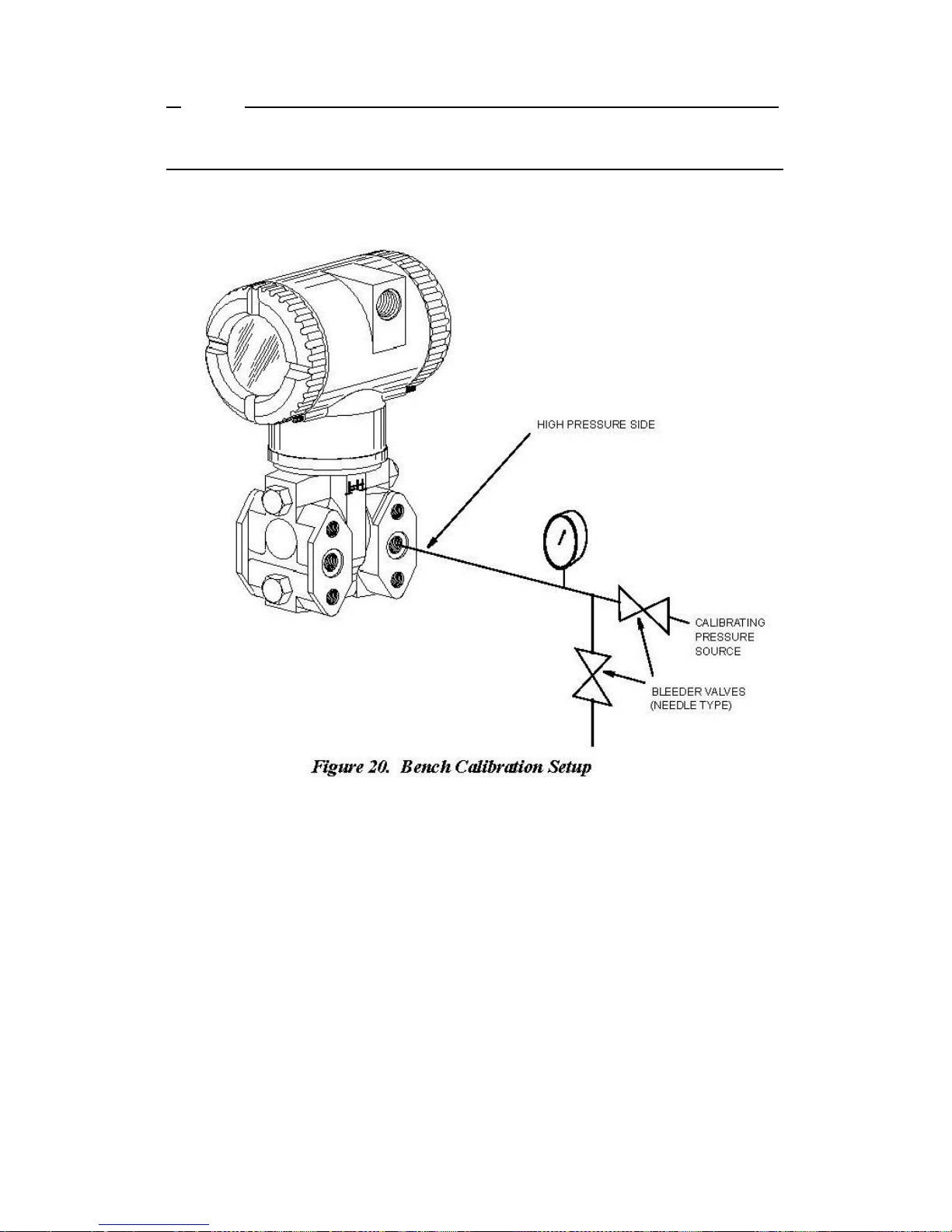
Bench Calibration Setup................................................................................................................. 30
General Calibration Setup .............................................................................................................. 31
Notes for Electronic Version –A and -V.......................................................................................... 32
Calibration and Configuration Using the Local Display .................................................................. 34
Calibration ......................................................................................................................... 36
IDP10-A and IDP10-V Calibration .................................................................................. 37
Zero Adjustment Using External Zero Button ................................................................... 38
Configuration .................................................................................................................... 38
IDP10-A and IDP10-V Configuration .............................................................................. 40
Re-ranging and IDP10-A or IDP10-V Transmitter .......................................................... 42
IDP10-A and IDP10-V Character Lists ............................................................................ 43
Testing the Display ......................................................................................................................... 44
Error Messages .............................................................................................................................. 45
4. Maintenance.................................................................................................................................. 47
Parts Replacement ......................................................................................................................... 47
Replacing the Electronics Module .................................................................................... 47
Removing and Reinstalling the Housing Assembly ........................................................... 48
Replacing the Sensor Assembly ........................................................................................ 48
Replacing the Terminal Block Assembly ........................................................................... 50
Rotating Process Covers for Venting ............................................................................................. 50
Index ........................................................................................................................................................... 52
[3]
98MANALIDP10AV Rev. A 8/16/11
Page 4

Figures
1 Transmitter Identification ...................................................................................................................... 6
2 Minimum Allowable Absolute Pressure vs. Process Temperature w/Fluorinert Fill Fluid ................... 9
3 Process Mounted Transmitter ............................................................................................................ 13
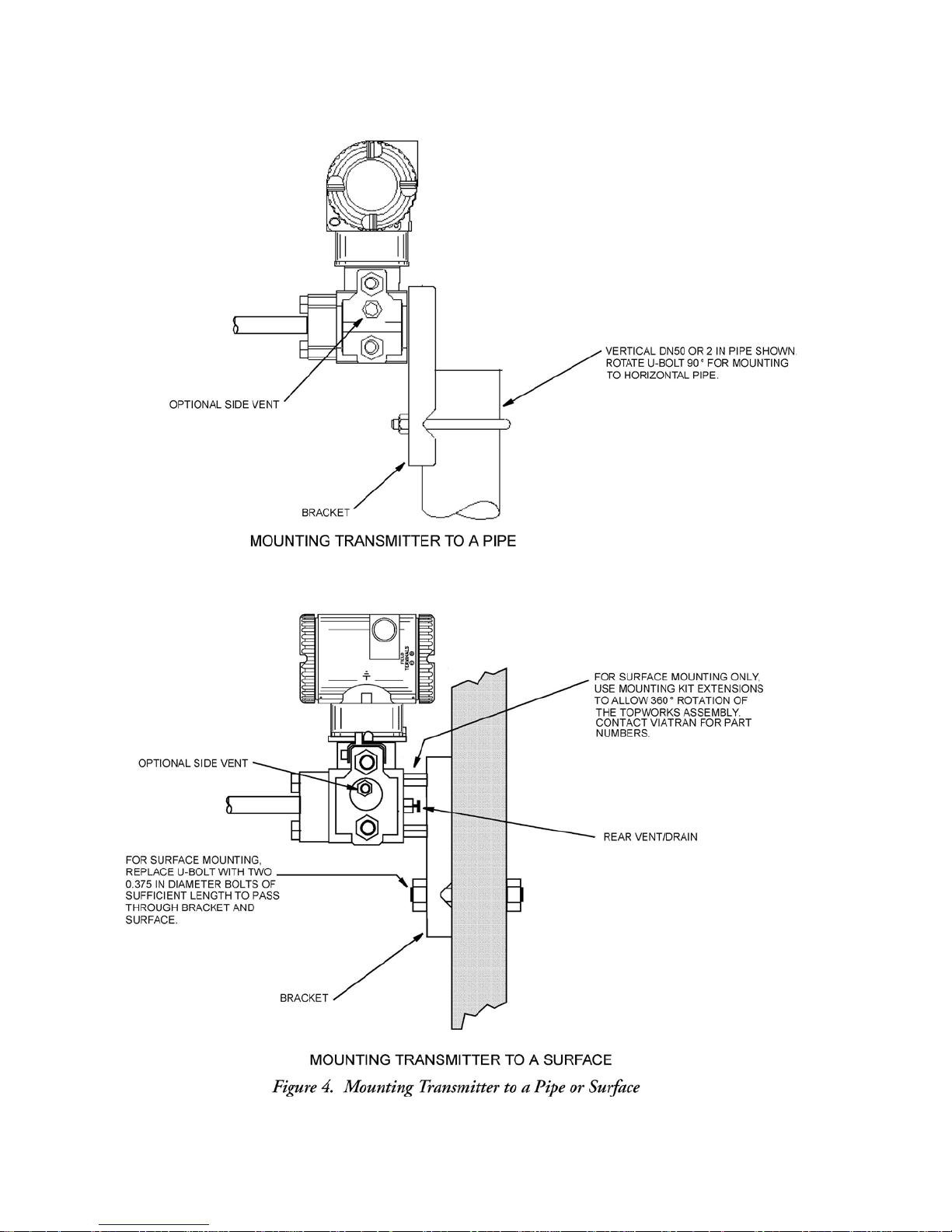
4 Mounting Transmitter to a Pipe or Surface ........................................................................................ 14
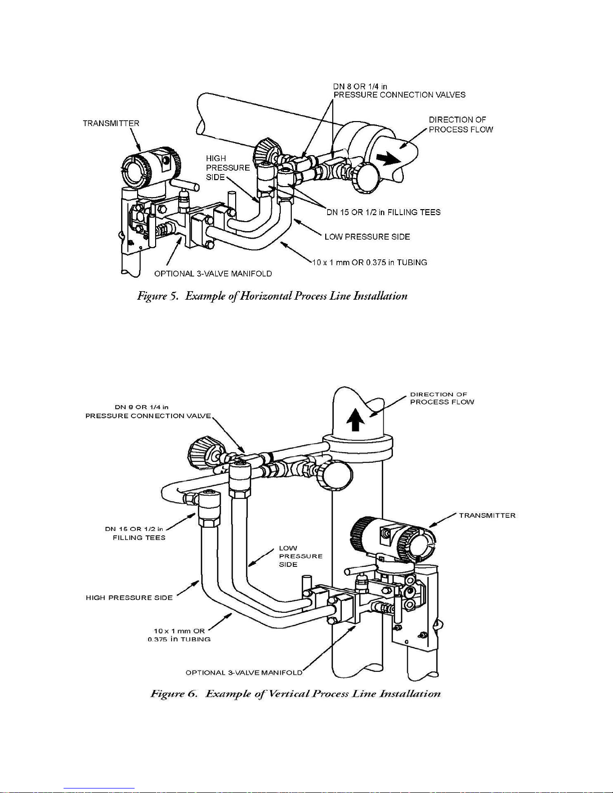
5 Example of Horizontal Process Line Installation ................................................................................. 16
6 Example of Vertical Process Line Installation ..................................................................................... 16
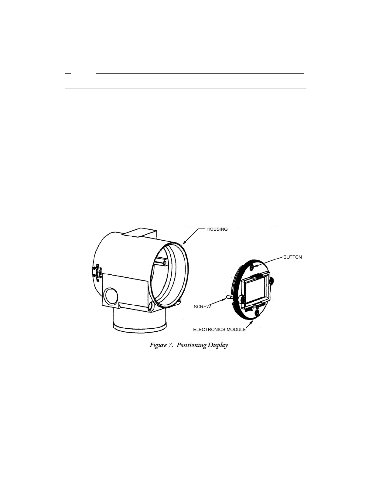
7 Positioning Display .............................................................................................................................. 18
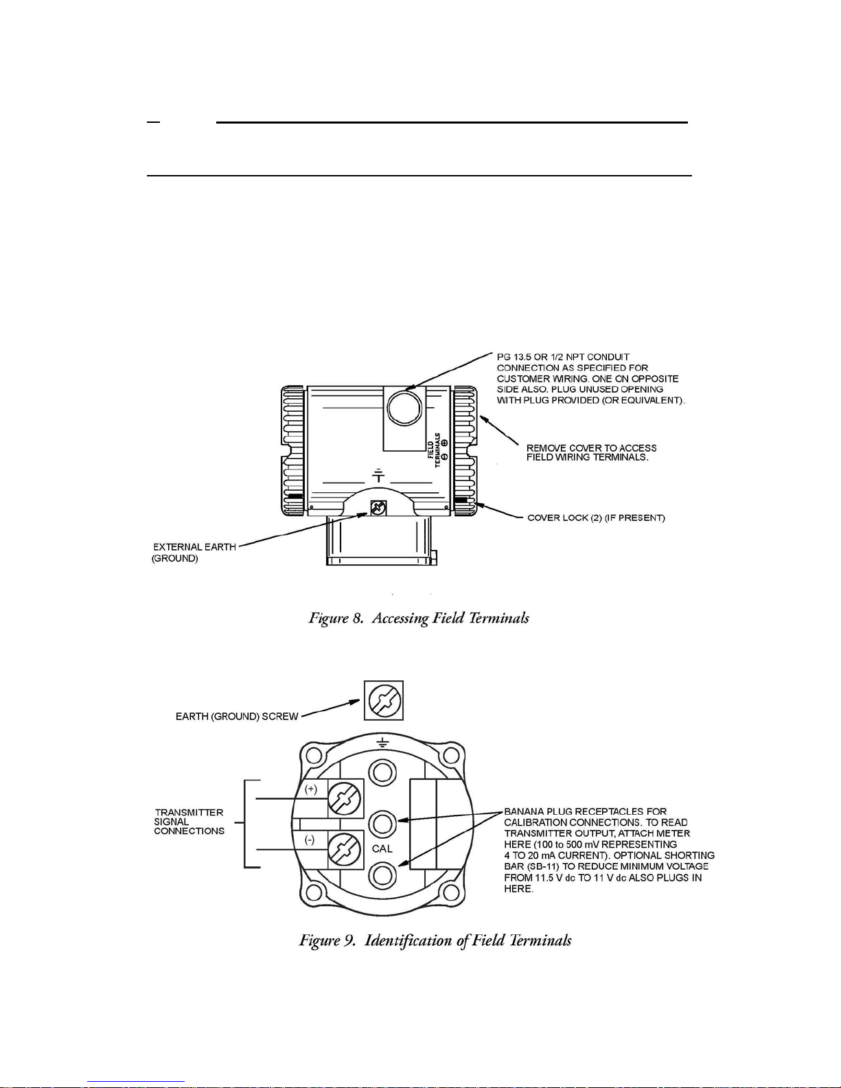
8 Accessing Field Terminals ................................................................................................................... 19
9 Identification of Field Terminals ......................................................................................................... 19
10 Supply Voltage and Loop Load ............................................................................................................ 20
11 Loop Wiring ......................................................................................................................................... 21
12 Wiring Several Transmitters to a Common Power Supply .................................................................. 22
13 Identification of Field Terminals .......................................................................................................... 23
14 Three-Wire Connection ....................................................................................................................... 24
15 Four-Wire Connection ......................................................................................................................... 24
16 Loop Wiring ......................................................................................................................................... 25
17 Wiring Several Transmitters to a Common Power Supply (Four-Wire) .............................................. 26
18 Field Calibration Setup ........................................................................................................................ 30
19 Calibration Setup of Electronic Equipment ......................................................................................... 30
20 Bench Calibration Setup ...................................................................................................................... 31
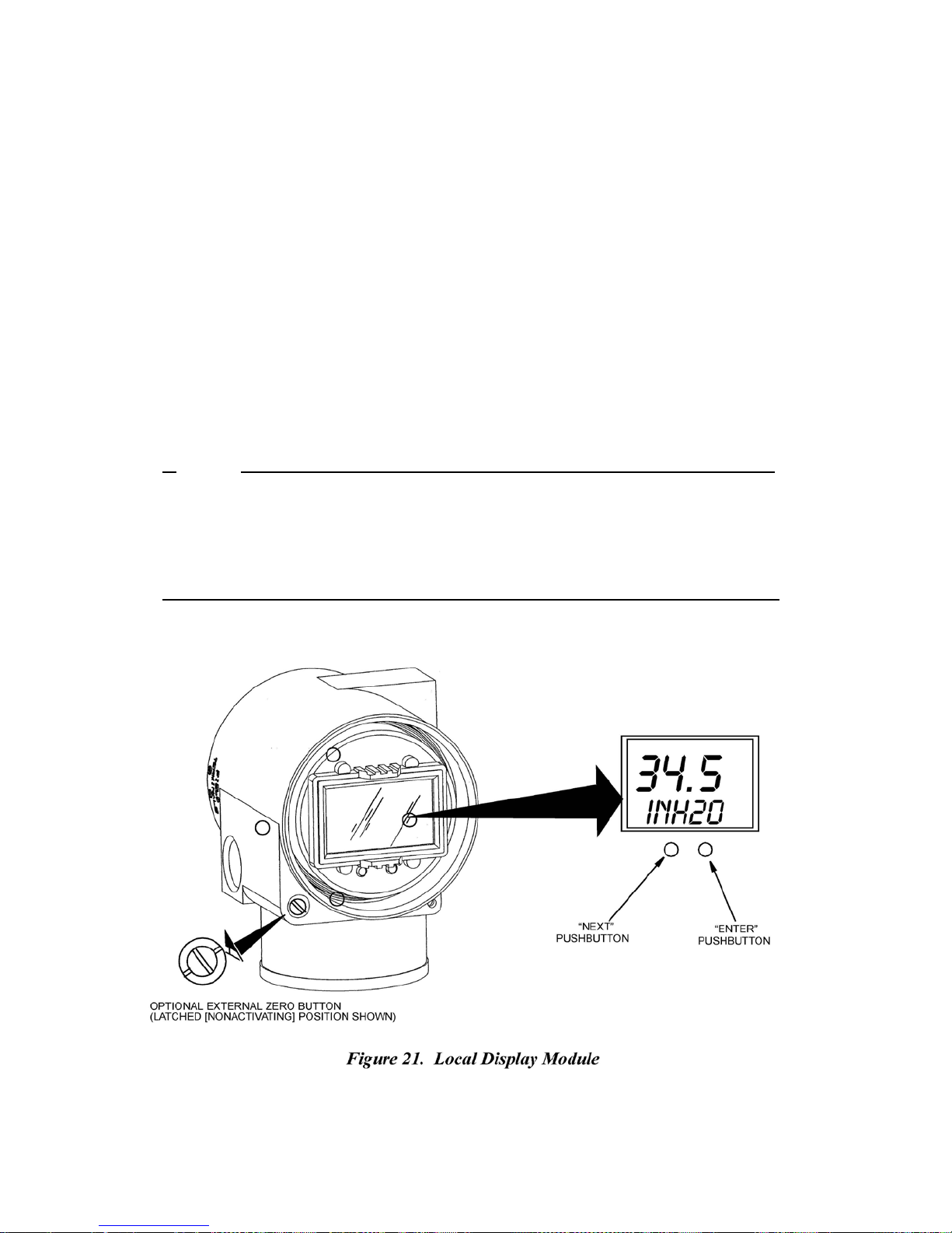
21 Local display Module ........................................................................................................................... 34
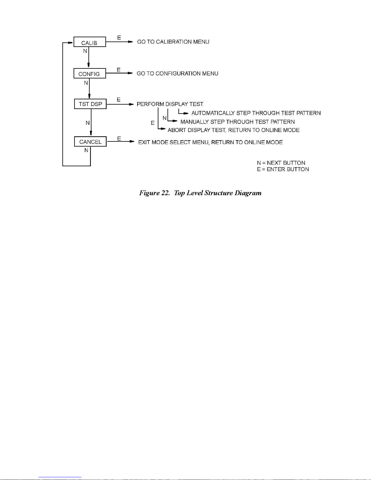
22 Top Level Structure Diagram ............................................................................................................... 35
23 Calibration Structure Diagram ............................................................................................................. 37
24 Configuration Structure System .......................................................................................................... 40
25 Display Test Segment Patterns ............................................................................................................ 44
26 Replacing the Sensor Assembly ........................................................................................................... 49
27 Replacing the Sensor Assembly (Code 78/79 pvdf Inserts) ................................................................. 49
28 Sensor Cavity Venting and Draining .................................................................................................... 51
[4]
98MANALIDP10AV Rev. A 8/16/11
Page 5

Tables
1 Electrical Safety Specifications .............................................................................................................. 11
2 Calibration Menu ................................................................................................................................... 36
3 IDP10-A and IDP10-V Configuration Menu ........................................................................................... 38
4 Alphanumeric Character List ................................................................................................................. 43
5 Numeric Character List .......................................................................................................................... 43
6 Error Messages ...................................................................................................................................... 45
[5]
98MANALIDP10AV Rev. A 8/16/11
Page 6
1. Introduction
General
The IDP10-A and IDP10-V Differential Pressure Transmitters measure the difference between two
pressures applied to opposite sides of a silicon strain gauge microsensor within
This microsensor converts differential pressure to a change in
converted to a 4 to 20 mA or 1to 5 VDC signal
of differential pressure. The
the same two wires
The transmitters are often used for measuring fluid flow across a primary device such as an orifice
Description
that
supply power to the transmitter
measurement
the
sensor assembly.
resistance.
proportional
signal for the IDP10-A is transmitted to remote receivers over
to differential pressure or to the square root
electronics.
The resistance change is then
plate, but can also be used for other types of differential pressure measurements such as liquid level,
interface level, or density measurements.
Reference
This document contains descriptions and instructions for transmitter installation, configuration,
calibration, and
Documents
maintenance.
Transmitter
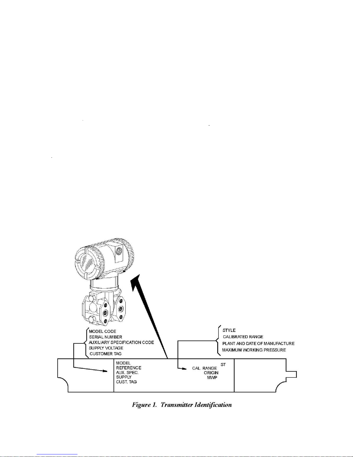
See Figure 1 for transmitter data plate contents. When the transmitter is powered, the firmware
revision is shown on the top line of the display.
Identifica
tion
[6]
98MANALIDP10AV Rev. A 8/16/11
Page 7
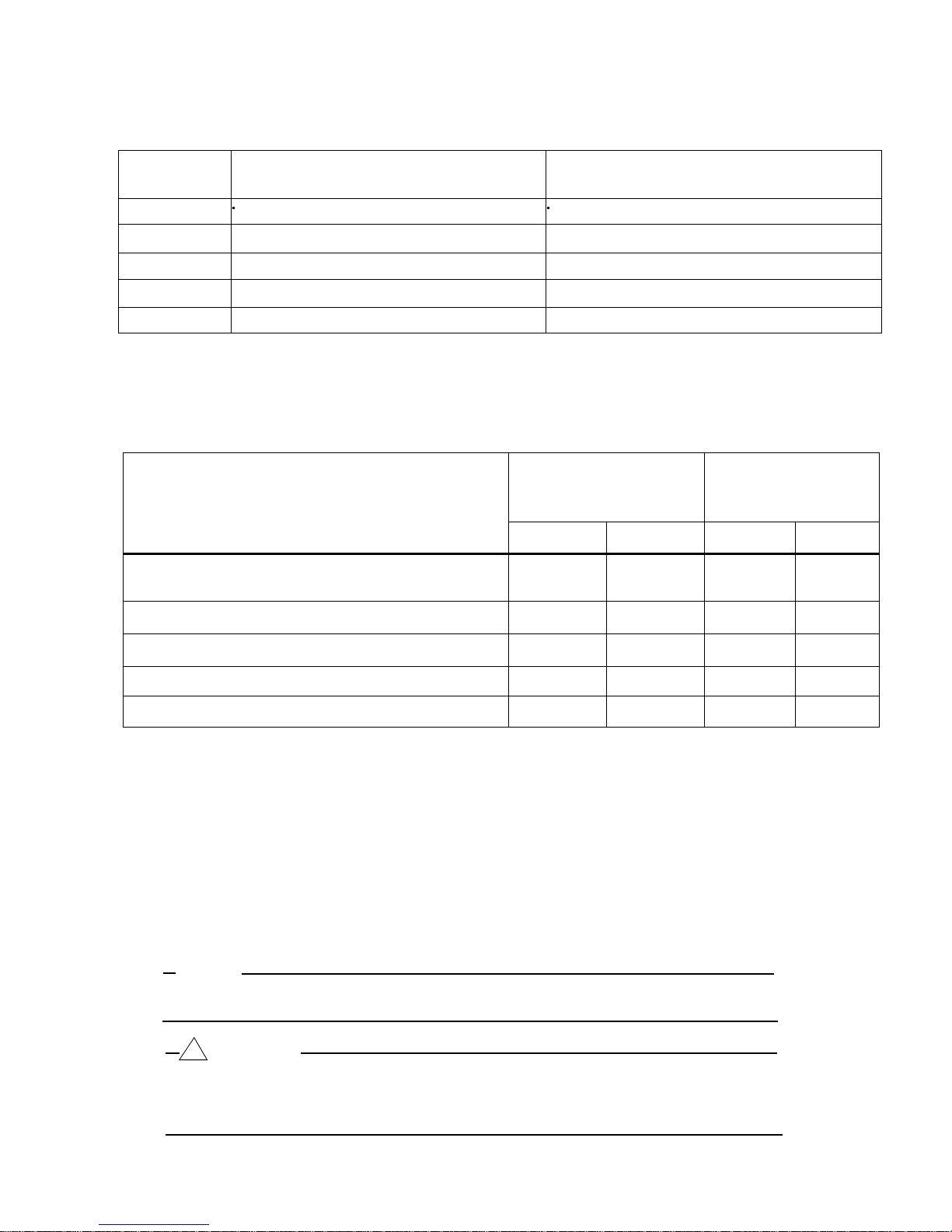
Span Limits
A
Standard
Span and Range Limits
Span Limit
Elevated Zero and
Standard (B7 steel), Option "-B2" (17-4 PS ss), Option
“-D3” or “-D7”(c)
Specifications
Code
0.12 and 7.5 kPa (0.5 and 30 inH2O) -7.5 and +7.5 kPa (-30 and +30 inH2O)
B
C
D
E
Negative values
Positive values indicate
For
applications requiring
range limits
of the
Transmitter Configuration
0.87 and 50 kPa (3.5 and 200 inH2O) -50 and +50 kPa (-200 and +200 inH2O)
7.0 and 210 kPa (28 and 840 inH2O) -210 and +210 kPa (-840 and +840 H2O)
0.07 and 2.1 MPa (10 and 300 psi) -0.21 and +2.1 MPa (-30 and +300 psi)
0.7 and 21 MPa (100 and 3000 psi) -0.21 and +21 MPa (-30 and +3000 psi)
of
differential pressure indicate
high side of
Suppressed Zero
an
transmitter
∆
P
low side of
sensor
at the
elevated
or
suppressed zero,
can not be exceeded.
Bolting
Material
higher
sensor
at the
higher
pressure.
the
maximum span
Maximum Static
Over-range Pressure
Rating(a,e)
MPa
25
Range Limits
∆
P
pressure.
and the upper and
and
Psi
3625
lower
Proof
MPa
100
Pressure
Rating(b)
14500
Psi
Option “B1” (316 ss) or Opti on "-D5"(c) 15 2175 60 8700
Option AS-B7M (B7M) 25 3625 100 14500
Option “-D1”(c) 16 2320 64 9280
Option “-D2”, “-D4”, "-D6", or "-D8"(c,d) 10 1500 40 6000
(a) Either side can be at the higher pressure during over-range.
(b)
Meets ANSI/ISA
(c)-D1 = DIN
-D2 = DIN Double ended
-D3 = DIN
-D4 = DIN Double ended
-D5 = DIN
-D6 = DIN Double ended
-D7 = DIN
-D8 = DIN Double ended
(d)Limited
(e)When
maximum over-range is 2.1 MPa (300 psi) and temperature limits are -7 and +82°C (20 and 180°F).
to
Structure Codes
Standard S82.03-1988.
Single
ended
Single
ended
Single
ended
Single
ended
operating temperatures ranging
NOTE
Static pressure zero shift
zero
output at nominal
!
CAUTION
1.
Exceeding
degrading its
2. The
the
maximum over-range pressure
performance.
transmitter
process cover
process cover
process cover
process cover
process cover
process cover
process cover
process cover
78/79 are
for
all calibrated spans
with M10 bolting.
with M10 bolting
with 7/16 in bolting.
with 7/16 in bolting.
with 7/16 in 316
with 7/16 in 316
with 7/16 in 17-4
with 7/16 in 17-4
from 0 to 60 °C (32 to 140°F)
used (pvdf inserts
operating static pressure.
could be nonfunctional
[7]
ss
bolting.
ss
bolting.
ss
bolting.
ss
bolting.
in the Hi and Lo
can be
eliminated
can
cause damage
after application
side process covers),
by
readjusting
to the transmit
of the proof pressure
the
the
ter
.
98MANALIDP10AV Rev. A 8/16/11
Page 8

Influence
Operative Limits
Sensor Body Temperature
pvdf Inserts
-7 and +82°C (20 and 180°F)
Electronics
Temperature
With LCD
Display
-40 and +85°C (-40 and +185°F)(a)
Relative Humidity
0 and 100%
Supply Voltage
IDP10-A 11.5 and 42 VDC(b)
Output Load
IDP10-A 0 and 1450 Ohms
Mounting Position
No Limit
Output Signal
4 to 20 mA dc linear, 4 to 20 mA dc square root, or 1 to 5 VDC, software selectable,
locally configurable using pushbuttons on the transmitter.
Zero and Span
Adjustable
moisture sealed pushbutton
housing
Adjust
at the
cover.
ments
transmitter using
assembly allows local resetting
the
local display.
An optional
of
zero
external se
lf-contained
without removing
Field Wiring Reversal
Accidental reversal
limited to 1 A or
1
A will
not
block assembly
less
damage
and
of
field wiring will
by
active
current limiting or loop
the
electronics
module or
external instruments
not
damage
in the loop.
the
sensor
transmitter, provided
the current is
resistance. Sustained currents
but could
damage
the terminal
of
Mounting
The
piping. It can
using
any
“Positioning Housing”
of four
NOTE
Position effect zero
output after installa
Adjustable
The transmitter
setting
an 80% input step
Operative
Pos
ition
transmitter
can be mounted in any orientation. It can be
also
be mounted
an optional mounting
desired
position for
access
on
different positions
shift for all
tion.
Damping
response
of 0.00 (none), 2, 4, or 8,
as defined
Limits
directly
bracket.
to
adjustments, display,
page
13. The
at 90°
increments. See “Positioning Display”
calibrated spans
time is
normally
seconds, whichever is greater,
in
ANSI/ISA
to a
The
vertical
housing
display
1.0
second
S51.1.
supported
or
horizontal
pipe or
can be rotated up to one
can
also
can be
or the
or conduit
be rotated in the
eliminated
connections.
by re
electronically
for a 90%
by the
process
surface mounte
full
turn to
See
housing
on
page
adjusting
adjustab
recovery
to any
13.
zero
le
from
d
Silicone Fill Fluid
Fluorinert Fill Fluid
(a)
Display updates are slowed
(b) 11 V dc with optional
-46 and +121°C (-50 and +250°F)
-29 and +121°C (-20 and +250°F)
IDP10-V 9 to 15.5 VDC
IDP10-V 10 MegOhms
and
readability decreased below temperatures
shorting block (AS code
[8]
of -20 °C (-4°F).
SB-11
98MANALIDP10AV Rev. A 8/16/11
Page 9
Sensor
Fill Fluid
Silicone
Oil (DC 200), or Fluorinert (FC-43).
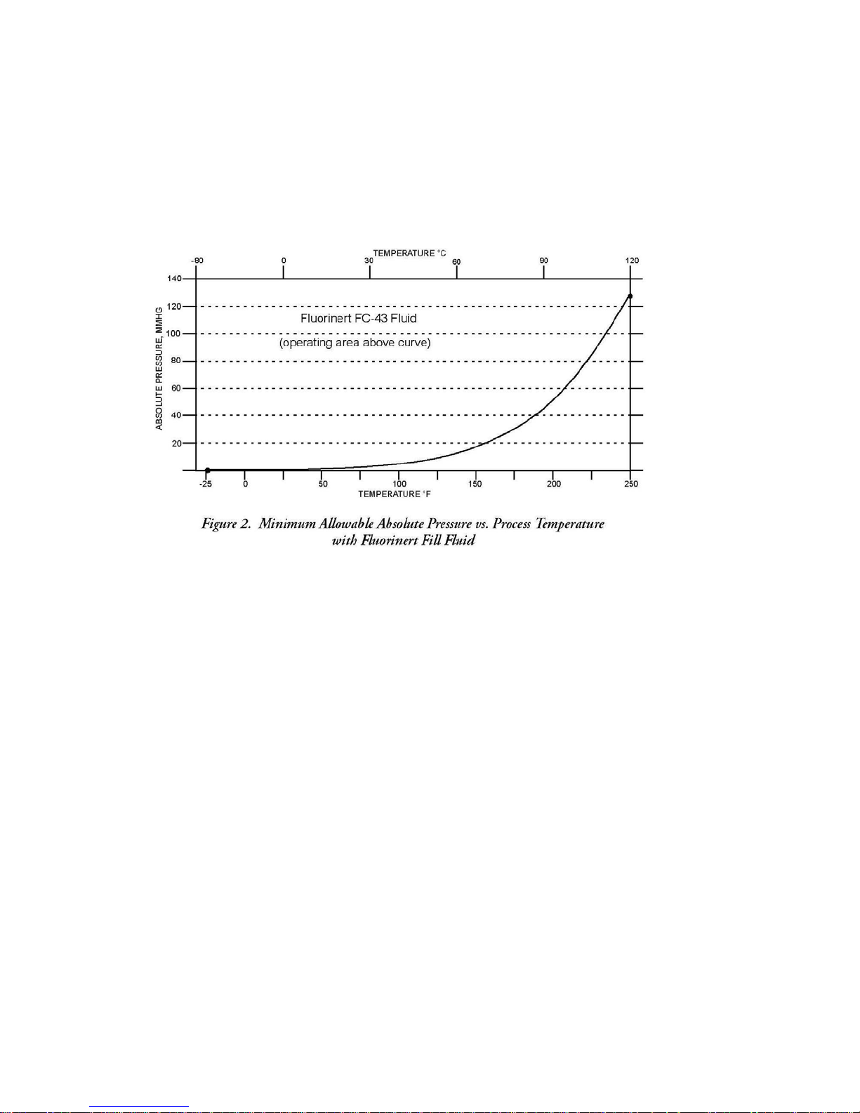
Minimum Allowable Absolute Pressure vs. Process Temperature
With
Silicone Fill
With Fluorinert
Fluid
Fill
Fluid
At
full vacuum:
Refer
to
Figure
Up to 121°C (250°F)
2.
Power-Up
Less
electronic
Elec
trical
Field wires
electronics housing. Leads
terminal
environmental,
plugged
Process Connections
IDP10
number of optional
Supply
Time
than 2.0
seconds
damping rate to the
Connections
enter through PG 13.5 or 1/2 NPT threaded
block
with metal plug
transmitters
Current
for output to
final measured variable
terminate under
in the
field
terminal compartment. To maintain RFI/EMI,
and
explosion proof ratings,
(provided), inserted
are
connected
process connectors
reach approximately
screw terminals
unused conduit connection
to
five
to the
process via
.
3.5
mA,
and then at the
value.
full
entrances
turns.
and
on either
washers
side
on the
must
of the
be
a 1/4 NPT thread or any one of a
Power supply must be capable of providing 22 mA current for the IDP10-A and 3 mA
current for the IDP10-V. Ripple of up to 2 V pp (50/60/100/120 Hz) is tolerable, but
instantaneous voltage must remain within specified range.
[9]
98MANALIDP10AV Rev. A 8/16/11
Page 10

Electrical Ground
The transmitter
compartment and an
To
minimize galvanic corrosion, place
washer
and
(ground) the
trans
Test Po
mitter
ints
The banana plug receptacles (designated CAL) can be used to check transmitter output of
the IDP10-A. Measurements should be 100 to 500 mV dc for 0 to 100% transmitter
output. Refer to Figure 9.
Conne
is equipped
loose washer
shield
at the
.
cti
ons
with an internal ground connection within the
external
ground
on the
external
field enclosure
connection
the
wire lead
ground
at the
or terminal
screw.
base
If
shielded cable
only. Do not ground the
of the
between
field
electronics
the captive
is
used,
shield
at the
wiring
housing.
earth
HHT Terminals
As
the top terminal
PC20, HART Communicator, or IFDC.
Approximate
Without
With
Process
With Optional 316
Process Wetted
Diaphragm:
Covers
and
is blocked, this transmitter does
Mass
Process Connectors
3.5 kg (7.8 lb)
Connectors 4.2 kg (9.2 lb)
ss
Housing Add 1.1 kg (2.4 lb)
Materials
316L
Process Connections:
ss,
Co-Ni-Cr,
Hastelloy
316
ss,
not
communicate
C, gold plated 316L
carbon
steel, Hastelloy
with the HHT, PC10,
ss,
Monel, or tantalum
C, Monel, or
pvdf inserts
Product Safety
To
prevent possible explosions
protection, observe applicable wiring practices. Plug unused
provided
!
To maintain IEC IP66 and NEMA Type 4X protection, the unused conduit opening
must be
T
urn
as
possible
!
DANGER
metal pipe plug,
WARNING
plugged.
covers
until O-ring
(at
Specifications
and to maintain
which engages
In addition, the threaded
contacts housing;
least
1/4 turn).
explosion proof,
dust-ignition proof
conduit
a minimum of
housing covers
five
full threads.
must be
installed.
then continue to hand tighten
[10]
98MANALIDP10AV Rev. A 8/16/11
opening
as
with the
much
Page 11

C
NOTE
1.
These transmitters have
listed
in Table 1. For
approvals and
2.
Wiring
are
restrictions
provided
certifications,
in the
Testing
Types of
and
CSA intrinsically safe for Class I,
Division 1, Groups A, B, C, and D; Class
II, Division 1, Groups E, F, and G; Class
III, Division 1.
CSA explosion proof for Class I, Division
1, Groups B, C, and D; Dust ignition
proof for Class II, Division 1, Groups E,
F, and G; Class III, Division 1.
CSA for Class I, Division 2, Groups A, B,
C, and D; Class II, Division 2, Groups F
and G; Class III, Division 2.
Area
Laborator
y,
Protection,
Classification
been
detailed
designed
information or status of testing
to meet the
electrical safety description
contact Viatran.
required to maintain
“Transmitter
Wiring”
electrical certification
section
of
this
document on
Table 1. Electrical Safety Specifications
Application Condition
Connect per CD 0629. Temperature
Class T4A at 40°C (104°F) and T3C at
85°C (185°F) maximum ambient.
IDP10-V only.
Temperature Class T6 at 80°C (176°F),
and T5 at 85°C (185°F) maximum
ambient.
Connect to source not exceeding 42.4
V. Temperature Class T6 at 40°C
(104°F) and T4A at 85°C (185°F)
maximum ambient. IDP10-V only.
laboratory
of the transmitter
page
Electrical
s
Design Code
15.
Safety
FM intrinsically safe for C l a s s I, Division
1, Groups A, B, C, and D; Class II,
Division 1, Groups E, F, and G; Class III,
Division 1.
FM explosion proof for Class I, Division
1, Groups B, C, and D; Dust ignition
proof for Class II, Division 1, Groups E,
Connect per CD 0629. Temperature
Class T4A at 40°C (104°F) and T4 at
85°C (185°F) maximum ambient.
IDP10-V only.
Temperature Class T6 at 80°C (176°F),
and T5 at 85°C (185°F) maximum
ambient.
F, and G; Class III, Division 1.
FM nonincendive for Class I, Division 2,
Groups A, B, C, and D; Class II, Division
2, Groups F and G; Class III, Division 2.
Connect to source not exceeding 42.4
V. Temperature Class T6 at 40°C
(104°F) and T4A at 85°C (185°F)
maximum ambient. IDP10-V only.
F
[11]
98MANALIDP10AV Rev. A 8/16/11
Page 12

2. Installation
The following material provides information and procedures for installing the IDP10-A and
IDP10-V Differential Pressure Cell Transmitter.
!
CAUTION
To
avoid damage
impact
Use a suitable
wrench
NOTE
to the
or
stamping device,
thread
sealant
transmitter sensor,
on the
on all connections.
do not
trans
mit
use
any impact
ter
.
devices, such as
an
Transmitter
The
transmitter
vertical
or
horizontal
NOTE
1. If the transmitter is not
Figure
2. The
transmitter should
draining into the
threaded
connections.
Mounting
can be
supported
pipe or
4,
readjust zero
conduit
by the
surface using
installed
output to
be mounted
field wiring
process
compartment can
piping
the optional mounting
in the
eliminate
so
as shown
vertical
the
that any
position
position zero
moisture condensing
exit
in
Figure
bracket shown
as shown
through one of the two
3, or mounted to a
in
Figure
in
Figure
effect.
or
4.
3 or
[12]
98MANALIDP10AV Rev. A 8/16/11
Page 13
Pr
ocess-
Mo
unted Transmitter
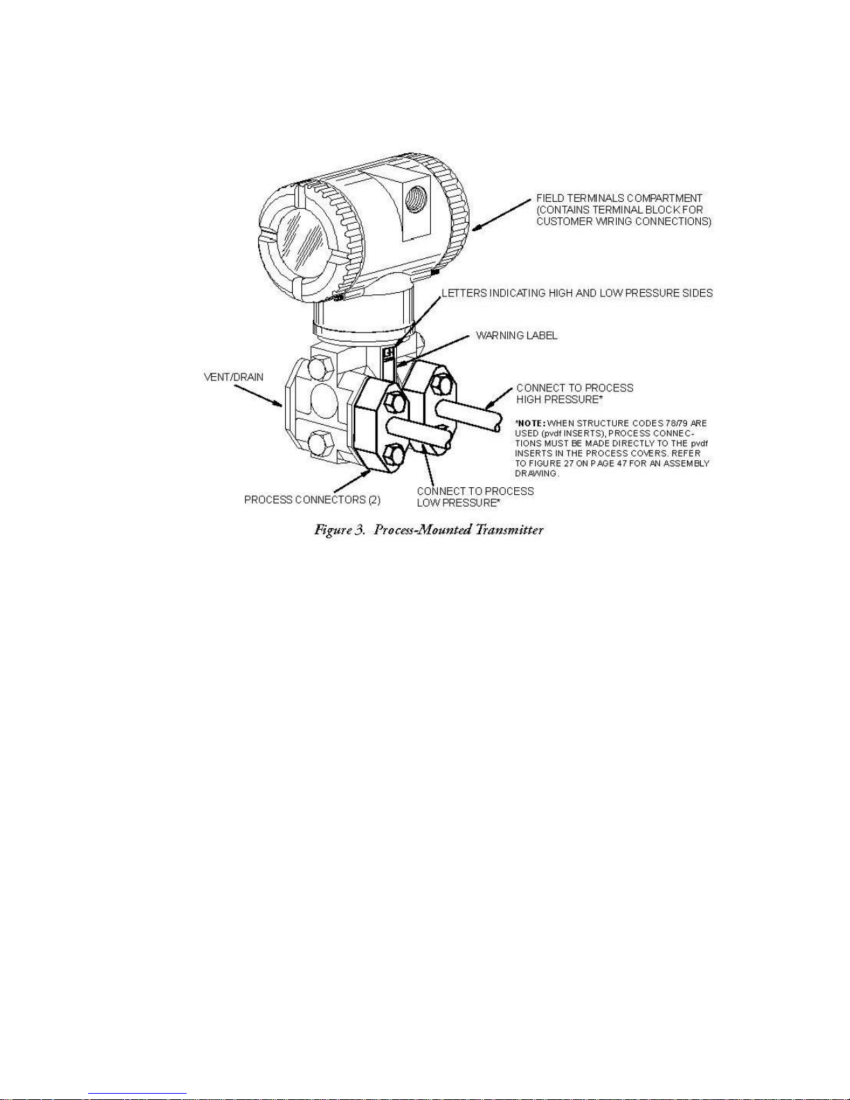
Figure 3 shows
the
transmitter
mounted to and supported by the
process
piping.
Pipe
To mount the
Option -M).
Referring
proor 2-in pipe. To mount to a
Figure
to a
360° rotation of the to
when the
or
Surface Mounted
transmitter
to
Figure
vided.
wall using
Mount the transmitter with mounting
4. The mounting
the U-bolt mounting
transmitter is
to a pipe or
4,
secure
bracket
p-
works assembly.
mounted to a
Transmitter
surface, use
the mounting
horizontal
pipe, turn U-bolt 90 from the position
can
also
holes.
surface as shown
the Optional Mounting Set (Model Code
bracket
be
Mounting kit
This
used
provides
to the
bracket
for
transmitter using
to a
vertical
wall
mounting by
extensions
better
access
in
Figure
4.
the two
or
horizontal,
securing
are
available
to the rear vent/drain
screws
shown
the
bracket
to
allow
DN 50
in
[13]
98MANALIDP10AV Rev. A 8/16/11
Page 14
[14]
98MANALIDP10AV Rev. A 8/16/11
Page 15

Installation of Flow
Figure
The
ment,
(for a
If the
lines
transmitter
flow,
(or
ter, the
mounted
tees.
Tighten drain
nector bolts to a torque of 61 N m (45 lb ft).
Note that the high and
the
With
5 and
Figure 6 show typical installations
transmitters
except
seal
liquid).
process fluid being measured
must be
the
lines are filled
water) is
tees
vertically (as shown).
side
of the
medium-viscosity seal liquids
NOTE
1. With a horizontal line,
the line.
of line.
2. With a
3. For liquid or steam
the
4. For gas
the
transmi
5. Viatran recommends the use of snubbers in installations prone to high levels of
flow
are
for
gas flow
filled
must be mounted
added to the
must be at the
plugs
sensor above
vertical
pressure connections
flow
pressure connections
tter should be mounted below the
pulsations.
Measurement
shown below
without a
with a
However,
suitable seal
below
with
water
lines
through the
same elevation (as shown
If a
and optional vent
low pressure sides
the
warning label as shown
with
line,
flow
flow,
without a
seal
with
the
level
of the
seal liquid),
must not
liquid
the
level
to protect the
filling tees.
seal
liquid
screws
of the transmitter
and/or
pressure connections
gas flow
should be upwards.
the
at the pipe.
liquid, the
at the pipe; for gas
long transmitter
without a
transmitter should
pressure connections
and with
come
in
(see procedure
of the
pressure connections
transmitter
in
is
not
to 20 N m (15 lb ft). Tighten the four
transmitter should
pressure
Piping
horizontal
filling tees
contact
To
prevent
Figure
required, elbows
in
Figure
at the pipe
seal
liquid,
be mounted lower than
flow
with a
and
vertical process
in the
with the
in next
from the hot
5) and the
are identified
lines, larger valve sizes should
connections.
transmitter,
section).
unequal
can be
3.
should
connections
be mounted
seal
liquid, the
pipes.
at the pipe
lines
at the pipe. With stea
steam.
heads
transmitter
by an L-H
be at the side of
(usual
to the
In such a
used
should be at
above
trans
the
transmitte
case,
The
seal
on the transmit
must be
in
place
process
marking
arrange-
be used.
mitter
the
m
liquid
of the
con-
on
top
r
-
[15]
98MANALIDP10AV Rev. A 8/16/11
Page 16
[16]
98MANALIDP10AV Rev. A 8/16/11
Page 17

Filling
If the
lines
System
process fluid being measured
must be
1. If the
2.
3. Open
4.
5.
6.
filled
transmitter is
of Operation” on
Close
both
all
Partially
transmitter body and
Refill
tee
Follow procedure
with
with a
process shutoff valves
three
open vent
connections. Replace plugs
suitable seal
in
page
valves
on
screws
for “Putting
Seal
service, follow
18.
lines. Close
Liquid
must not
liquid. The
.
3-Valve
Manifold.
on transmitter until
vent screws.
Transmitter
come
in
contact
procedure
the
procedure
all
and
close bypass valve.
into Operation” on
with the
to do this is
for
“Taking
air
has
transmitter,
as
the
Transmitter Ou
been
forced
Check for leaks.
page
the
follows:
out of
18.
transmitte
t
r
!
CAUTION
To
prevent loss
process shutoff valves
of
seal
liquid and contamination of
and
manifold shutoff valves
process
if
bypass valve is
fluid,
never
open.
open both
Positioning Housing
The
transmitter housing (topworks)
direction
nections.
when
viewed
!
CAUTION
1. Do not rotate the
there
is
doubt about the
then back off
Positioning
The
display
this,
refer
1. Turn
2.
can be rotated within the
to
Figure
off power source
Screw
in
rotating it counterclockwise.
from
housing
no more than one
Display
7 and
perform
cover lock
(if
can be rotated up to one full turn in the
above
for optimum
more than one turn from the
housing
rotational position, turn
full
turn.
access
housing
the following:
to transmitter.
present)
and
to any of four
remove
to
the
electronics
adjustments, display,
as received
fully clockwise
positions
compartment
position. If
at 90 °
increments.
counterclockwise
or conduit con-
and
To do
cover
by
3.
Remove electronics
and pulling out module.
4. If turning
display 180
module by
°, turn and return module to
unscrewing
[17]
two
screws closest
housing
to
sides
of
trans
mitter
by
reversing
98MANALIDP10AV Rev. A 8/16/11
Step 3.
Page 18
5. If turning
a.
NOTE
Plastic
buttons were
display 90
Remove
backside
° in either direction:
the two (2)
of the module.
not
plastic
provided
buttons
on
(plugs)
some early versions
by pushing them out from the
of the
electronics
module.
b.
Unscrew
the module at 90 ° from their
the two (2)
screws
from the module and then
original
position.
rethread
them
back
into
c. Insert the two (2)
(To order plastic buttons for earlier versions of the electronics modules or for
replacement, consult with the Factory.)
d. Return the module to the
6.
Reinstall
the
cover locks
until it
7.
Restore power
the
housing;
extends
cover
then continue to hand tighten
are
present, align
to transmit
plastic
onto the
into the
buttons into the two open
housing
housing
the
cover serration
ter
.
by
by rotating it
serration
to
reversing
as
in the
prevent
Step 3.
clockwise
much as
cover
unwanted
screw holes
until the O-ring contacts
possible
with the
cover
in the module.
(at
least
1/4 turn). If
lock
and
unscrew
rotation.
it
Cover
Electronic housing cover locks, shown
certifications
Transmi
The
Locks
and
tter Wiring
installation
and
as
part of the Custody
wiring
for
of your
in
Figure
Transfer Lock
8, are
IDP10-A
transmitter
must
[18]
provided as standard
and
Seal
option.
with
certain
agency
(4-20 mA Output Signal)
conform
to
local code requirements.
98MANALIDP10AV Rev. A 8/16/11
Page 19
NOTE
Viatran recommends the use of transient/surge protection in installations prone to
high levels of electrical transients and surges.
Accessing Transmitter
For
access
threaded cover
Note that the
Identification of
to the
field terminals,
and
remove
embossed letters
terminals is shown
the
Field Terminals
thread the
cover
FIELD TERMINALS
in
cover lock
from the
Figure
field terminals
9.
(if
present)
identify
into the
compartment
housing
as shown
to
the proper compartment.
clear
in
Figure
the
8.
[19]
98MANALIDP10AV Rev. A 8/16/11
Page 20
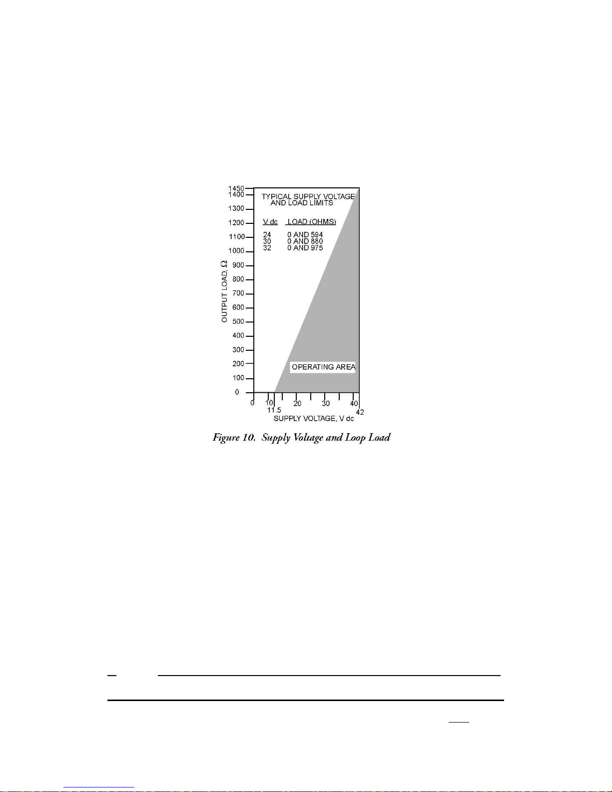
Wiring the
When
The
supply voltage
resistance
excluding
wiring
supply voltage vs.
(transmitter output load), add the
the transmitter. The
Transmitter
your
transmitter,
the output load
and
loop load resistance
to a Control Loop
the
supply voltage
relationship
in the
power supply must
and loop load must be within
is
shaded area
series resistance
be
shown
can be
capable
in
Figure
used.
of
each
of
supplying
10.
Any
To
determine
specified
combination of
limits.
the loop load
component in the loop,
22
mA
of loop current.
Ex
amples:
1. For a loop load
42 V dc.
2. For a
supply voltage
565
To
wire
one or more
1.
Screw
in
cover lock
resistance
of 24 V dc, the loop
transmitters
(if
present)
of 860 the
supply voltage
load resistance
to a
power supply, proceed
and
remove
the
field terminals
can be any
can be
with the
value
from 30 to
any value
from
following steps.
compartment
cover
zero to
by
rotating it counterclockwise.
2. Run
signal wires
conduit
4 to 20mA output from electrical noise. Screened (shielded) cable may be required
in some locations.
NOTE
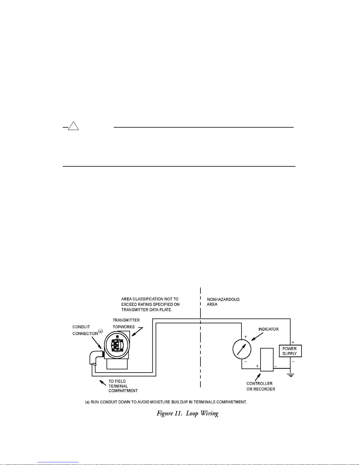
connections as shown
(0.50 mm2 or 20 AWG,
Do not run transmitter
3. If
shielded cable
is
wires
in
used,
earth (ground) the
in
Figure
same
typical)
11.
conduit
[20]
through one of the transmitter
Use twisted single
as
main (ac
shield
at the
power supply
pair to protect the
power)
wires.
98MANALIDP10AV Rev. A 8/16/11
only. Do
not
Page 21
ground the
the metal housing.
4. Plug unused conduit
(or
equivalent).
protection, plug must
recommended.
5. Connect an earth (ground)
practice.
!
CAUTION
If the
signal circuit must
terminal of the dc
possibility
one earth in a loop.
6. Connect the
connections shown
7. Connect
supply
8.
Reinstall
the
housing.
If
cover locks
until it
shield
at the transmitter. Cut and/or tape the
connection
To maintain
engage
be
earthed (grounded),
power supply.
of
short-circuiting groups
power supply
in
Figure
receivers (such
and
transmitter as shown
the
cover
Then continue to hand tighten
are
present, align
extends
into the
as
onto the
cover serration
shield
so it cannot contact
with the PG 13.5 or 1/2 NPT metal plug provided
specified explosion proof
a minimum of
wire
to the earth terminal in
To
avoid errors resulting
of
instruments
and
receiver
9.
controllers, recorders, indicators)
in
Figure
housing
by rotating it
the
serration
loop
11.
to
prevent
five
it
is preferable
in a loop, there should be only
wires
as
much
in the
and dust-ignition proof
full
threads.
from earth
to the
clockwise
as possible
cover
unwanted
Thread
accordance
to do
so
at the negative
loops
“+”
and “–” terminal
in
series
until the O-ring cont
(at
with the
cover
lock
rotation.
sealant
with local
with power
least
and
is
or the
1/4 turn).
unscrew
act
s
it
9. If
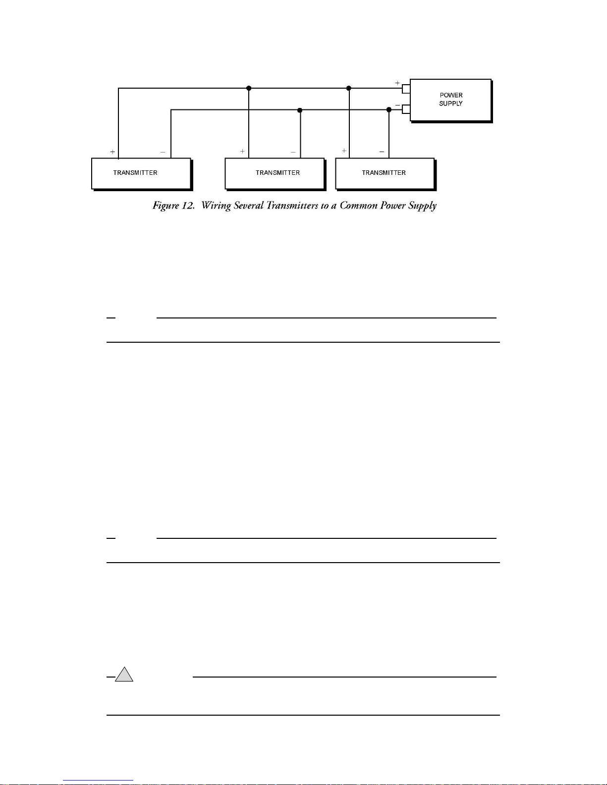
wiring additional transmitters
for
each additional
single power supply
transmitter. The
is
shown
in
Figure
to the
same power supply, repeat Steps
setup
with multiple
12.
1 through 8
transmitters connected
to a
[21]
98MANALIDP10AV Rev. A 8/16/11
Page 22
Putting Transmitter
The
following procedure explains
optional
not lost.
Taki
The
optional
not lost.
bypass manifold
Refer
to
NOTE
Procedure assumes
1. Make
2. Make
3.
4.
5.
ng
following procedure explains
NOTE
Procedure assumes
1.
2.
3. Open
4.
!
When
prevent possible
sure
sure
Slowly
Close bypass
Slowly
open
open
the
bypass manifold
Refer
to
Close downstream manifold
Close upstream manifold
bypass
Carefully
lines.
WARNING
venting pressure
into Operation
how to
to
ensure
Figure
5 or
Figure
that
Process shutoff valves
that both
that
upstream manifold
valve.
downstream manifold
upstream
bypass valve
Transmitter
how to
to
ensure
Figure
open the vent
5 or
Figure
that
Process shutoff valves
valve.
from the transmitter,
injury from
valve.
screw
process material, temperature,
sequence
that your
6.
and
downstream manifold
is open.
valve.
valve.
Out of
sequence
that your
6.
valve.
to
release
the
valves
in your
transmitter
are open.
is not
Operation
the
valves
in your
transmitter
are open.
any
wear suitable protective
[22]
is not
residual pressure before
flow measurement
over-ranged
valves are
and that
closed.
piping or
seal
liquid is
flow measurement
over-ranged
or pressure.
98MANALIDP10AV Rev. A 8/16/11
and that
disconnecting
equipment to
piping or
seal
liquid is
Page 23
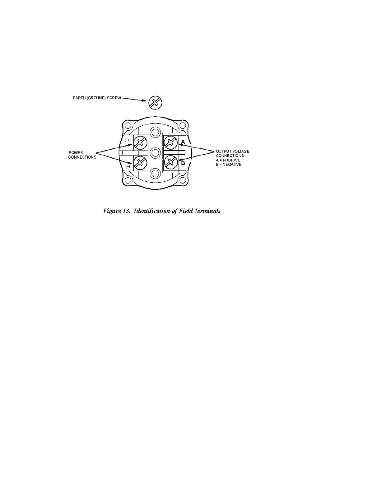
Transmitter Wiring for
The
field terminals
The transmitter
compartment and an
minimize galvanic corrosion, place
washer
field enclosure
on the
Power Supply Voltage
on a
transmitter
is
equipped with an internal ground connection within the
external
external
only. Do not ground the
ground
and Current
IDP10-V
with a 1 to 5 V dc output
ground
screw.
connection
the
wire lead
If
shielded cable is used,
shield
or
at the transmitter.
(1-5 VDC
signal are shown
at the
base
of the
terminal between
earth (ground) the
Output
electronics housing. To
the
captive washer
Signal)
in
field
wiring
shield
Figure
and
13.
at the
loose
The
power supply voltage across
15.5 V dc and the
conditions. Verify
least 9 V dc
power supply
that the
across
the transmitter input
the transmitter input
must be
power supply
capable
loop load
terminals
terminals
of
supplying
resistance
with a current draw of 3 mA.
can be any
3 mA of current under all
and
source impedance allow
value between
9 and
at
Output Load
The
receiver
input
impedance
can be any
value between
1 and 10 M.
Three
The transmitter
B) electrically connected internally. This means
wires
For
Figure
carrying
or
Four
for
wiring economy
relatively
14 can be
short
the
power supply
Wire
is supplied
wiring runs having low resistance, three-wire connections as shown
used
Connections
with a
or four
to
minimize wiring costs. However, a voltage
current
four-wire terminal block
wires
causes
that the
for
maximum
an error in the 1 to 5 V dc signal.
[23]
transmitter can
accuracy.
with the two
negative terminals
be
wired
drop in the common lead
98MANALIDP10AV Rev. A 8/16/11
with
(- and
either
in
three
Page 24
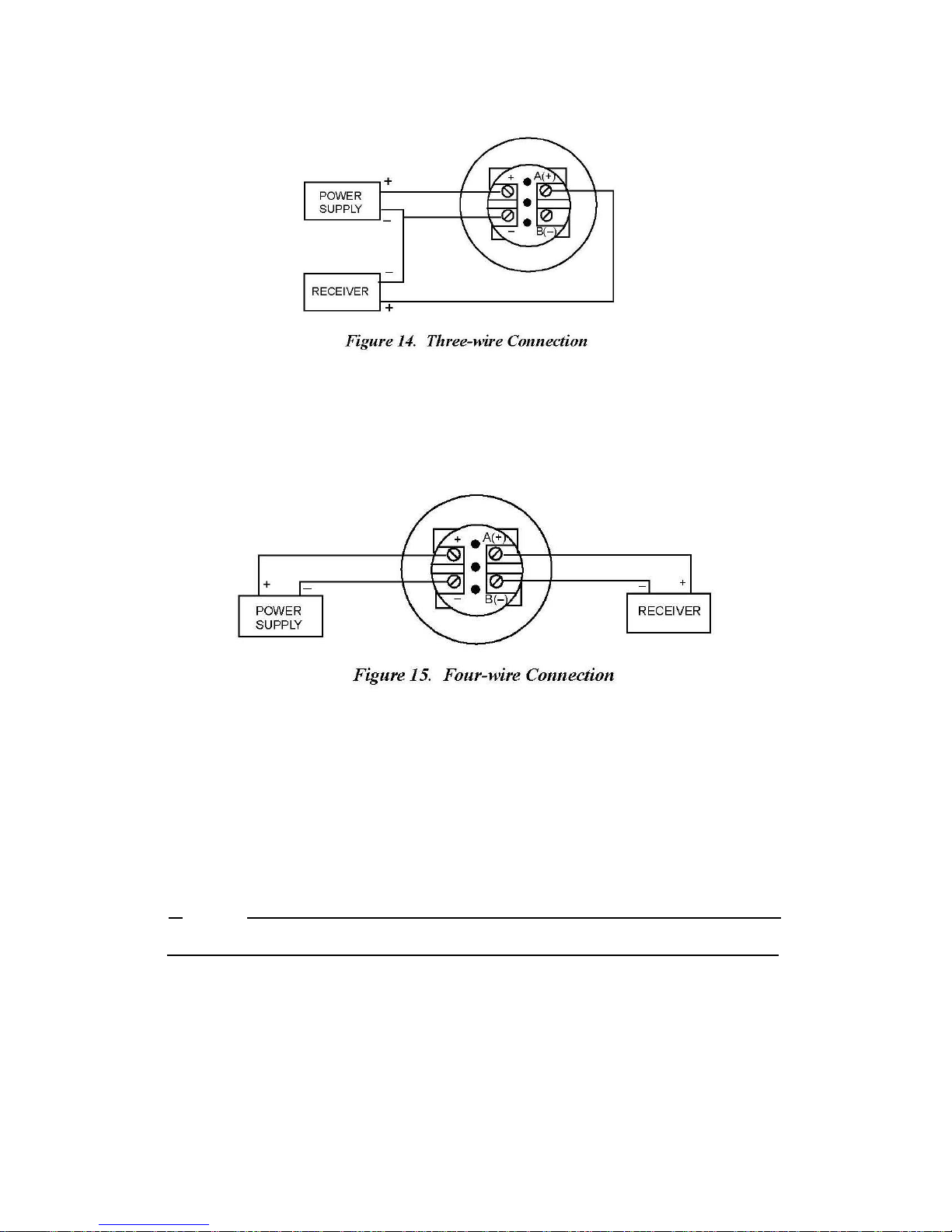
For
wiring
accuracy, a four-wire connection as
isolation.
affect
runs with high
With
four-wire configuration, voltage
measurement
resistance
accuracy.
due to long
shown in
lengths
Figure
drop in the
or other
15 can be
power supply
reasons,
used
or for maximum
to
provide input-outpu
loop
does
t
not
To
wire a transmitter, proceed
1.
Screw
in
cover lock
with the
(if
present)
following steps
and
remove
the
.
field terminals
compartment
cover
by
rotating it counterclockwise.
2. Run the
one of the
connection
5 V dc output from
NOTE
Do not run transmitter
supply voltage
transmitter
and output
conduit
is used, use twisted single
electrical noise.
wires
in
same
wires
connections as shown
conduit as
3. If
shielded cable is used,
the
housing
4. Plug
(or
shield
equivalent).
at the transmitter. Cut and/or tape the
.
unused
conduit connection with the PG 13.5 or 1/2 NPT metal plug provided
To maintain
protection, plug must
recommended.
earth (ground) the
specified explosion proof
engage
a minimum of
[24]
(0.50 mm2 or 20 AWG,
in
Figure
pair on the output
mains
shield
at the
shield
side
(ac
power)
receiver
so it cannot contact the metal
and dust
five
full
threads.
typical)
through
8. If four-wire
to protect the 1 to
wires.
only. Do not ground
-ignition proof
Thread
98MANALIDP10AV Rev. A 8/16/11
sealant is
Page 25
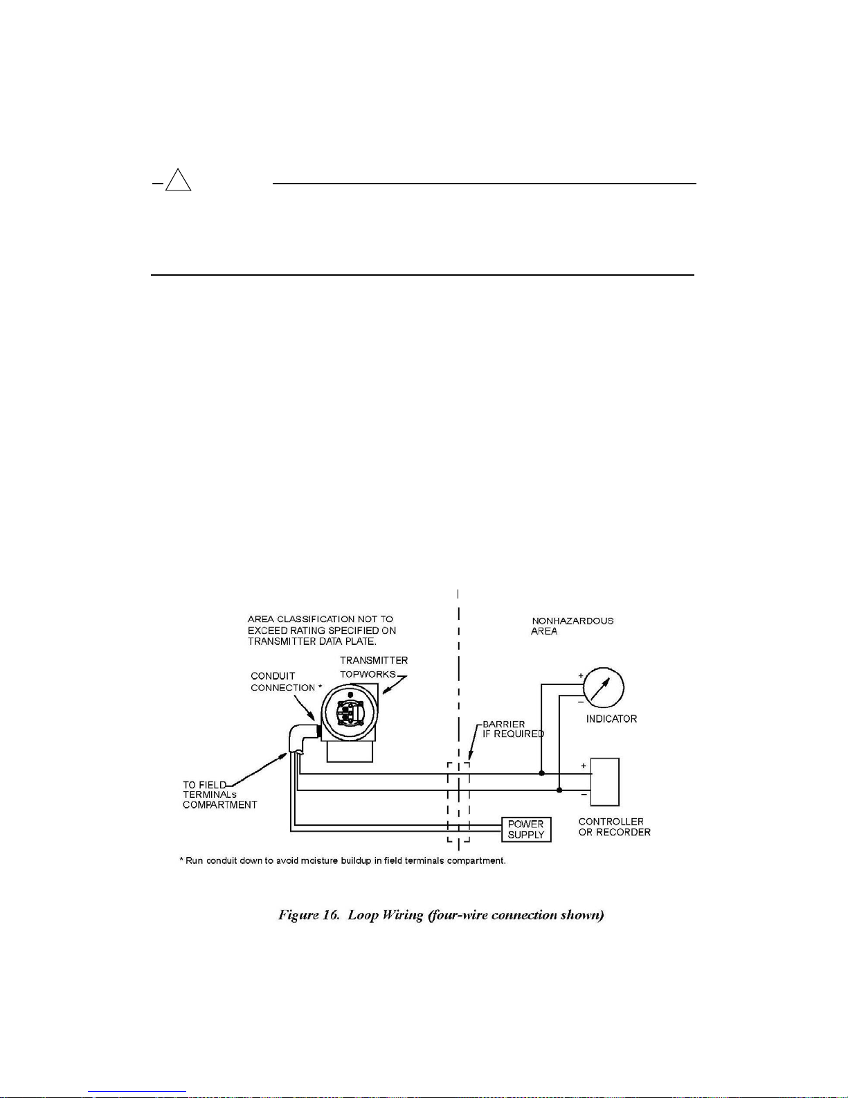
5. Connect an earth (ground)
wire
to the earth
terminal
in
accordance
with local
practice.
!
CAUTION
If the output circuit must be earthed
negative
possibility
terminal of the
of
receiver.
To
short-circuiting groups
(grounded),
avoid errors resulting
it
is preferable
to do so at the
from earth
loops
or the
of instruments in a loop, there should be only
one earth in a loop.
6. Connect the
shown
7.
Reinstall
the
housing.
If
cover locks are present, align
until it
8. If
wiring additional transmitters
for
each additional
single power supply is shown
power supply
in
Figure
the
cover
14 or
onto the
and
Figure
housing
15.
Then continue to hand tighten
extends
into the
cover serration
transmitter. The
in
receivers (such
Typical
loop
by rotating it
the
serration
to
prevent
to the
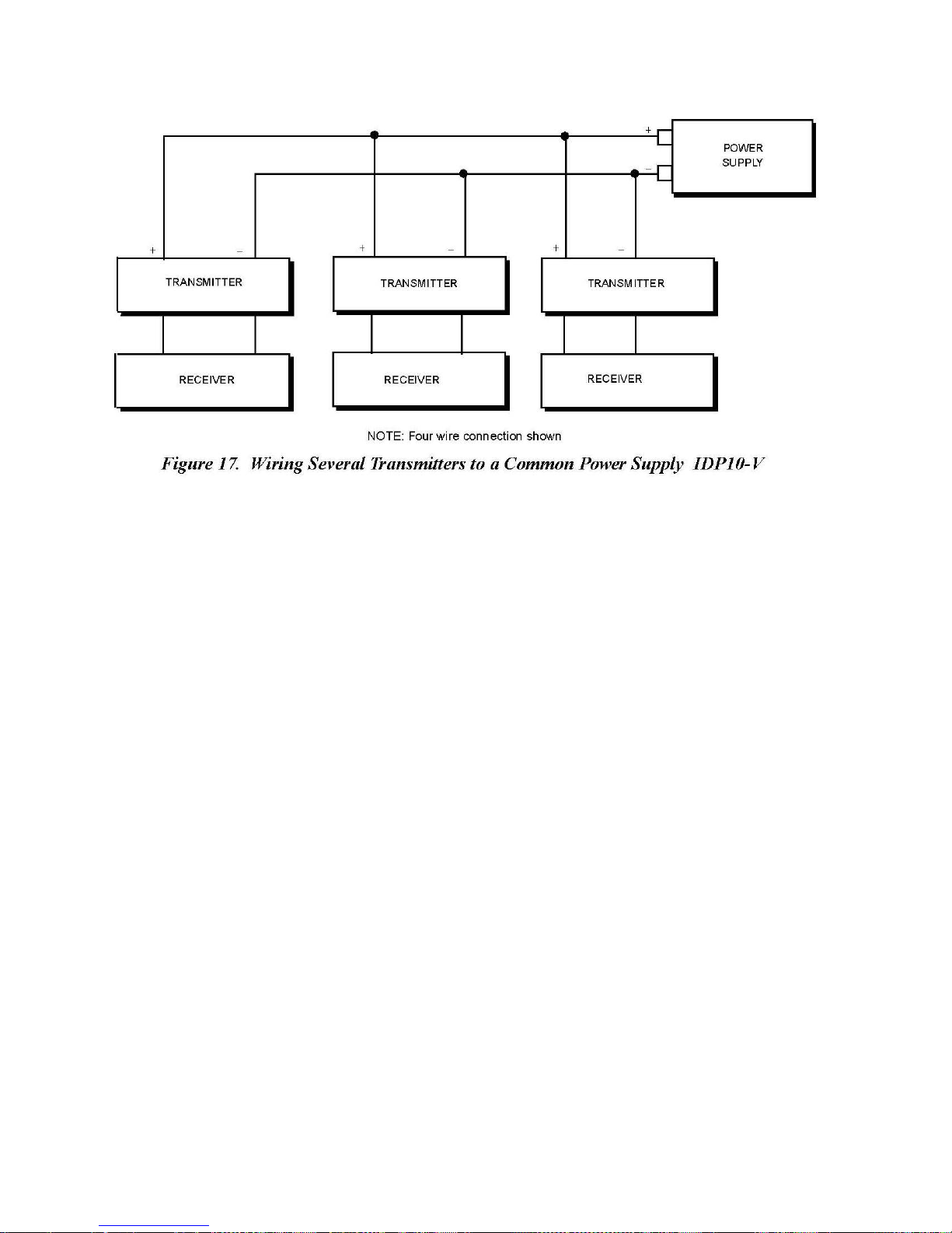
same power supply, repeat Steps
setup
with multiple
Figure
17.
as
controllers, recorders, indicators)
wiring is shown
clockwise
as
much
as possible
in the
cover
unwanted
with the
in
Figure
until the O-ring contacts
(at
least
lock
and
cover
rotation.
1 through 7
transmitters connected
as
16.
1/4 turn).
unscrew
to a
it
9. For
installations
one pair
output
shield
with the
with long
connected
terminals.
shield connected
to the
The two
runs,
Viatran
recommends using
power supply terminals
twisted
pair can be in
to the
receiver.
two
and one pair
connected
individual shields
The
shield
must not be
twisted
pair wit
to the
or a common
connected to
h
the transmitter.
[25]
98MANALIDP10AV Rev. A 8/16/11
Page 26
[26]
98MANALIDP10AV Rev. A 8/16/11
Page 27

Putting
Transmitter
The
following procedure explains
optional
not lost.
Taking
The
optional
not lost.
bypass manifold
Refer
to
Figure
NOTE
Procedure assumes
1. Make
2. Make
3.
4.
5.
following procedure explains
Procedure assumes
1.
2.
3. Open
sure
that both
sure
that
Slowly
Close bypass
Slowly
NOTE
Close downstream manifold
Close upstream manifold
open
upstream manifold
valve.
open
downstream manifold
the
bypass manifold
Refer
Transmitter
to
Figure
bypass
valve.
into Operation
how to
to
ensure
5 or
Figure
that
Process shutoff valves
upstream
bypass valve is
sequence
that your
6.
and
open.
valve.
Out of
how to
to
ensure
5 or
Figure
that
Process shutoff valves
valve.
sequence
that your
6.
valve.
the
valves
in your
transmitter is
are open.
downstream manifold
valve.
Operat
the
transmitter is
are open.
valves
not
not
ion
in your
over-ranged
flow measurement
over-ranged
valves are
closed.
flow measurement
and that
and that
piping or
seal
liquid is
piping or
seal
liquid is
4.
Carefully
lines
!
WARNING
When
prevent possible
venting pressure
open the vent
.
from the transmitter,
injury from
screw
to
release
process material, temperature,
any
residual pressure before
wear suitable protective
[27]
disconnecting
equipment to
or pressure.
98MANALIDP10AV Rev. A 8/16/11
Page 28

3.
Calibration and
!
CAUTION
Anytime Calibration
transmitter
the
transmitter comes back
before selecting
NOTE
1. For best
transmitter
2. Zero
be
3. When
root mode, return the output to the
apparent
the
4.
After calibrating transmitters
the
beyond 4 and 20 mA respectively.
output is
results
shifts resulting
eliminated
checking
instability
square
underrange
(CALIB) or
automatically set
online. Make
CALIB or CONFIG.
in
applications where
output once it
by
re-zeroing
the
in the output
root mode after the
and
overrange
has stabilized
from position
the transmitter outp
zero reading
Configuration
to 1 volt until Cancel or Save is
effects
of a transmitter operating in the
signal.
zero check
operating with a 4 to 20 mA output
output
Configuration
(CONFIG) mode is entered, the
sure
that the control loop is in manual
high
accuracy
at the final
and/or
linear
mode. This
Return the transmitter output to
is complete.
values
to
is required,
operating
static pressure effects
ut.
will eliminate
ensure
that they extend
temperature.
selected
re-zero
square
signal,
and
the
can
an
check
Calibration Se
The
following sections show setups
least
three
times as accurate as
simulating
ferential pressure,
The IDP10-A and IDP10-V transmitters can be re-ranged to a new calibrated range
without application of pressure. See EGU LRV and EGU URV in Figure 24.
the
NOTE
tup
process differential pressure.
to one
side
Field Calibration Setup
Field calibration is performed
must have bypass
following:
Access
or, the optional vent
If the transmitter is to be
tion
to the
Setup”
and
shutoff valves between
process connections
screw
procedure.
the
of the
without
in the
removed
for
field
or bench
desired accuracy
This is done by
transmitter
disconnecting
on the
side
from the
and then
the
non-process side
of the
process
process
calibration. Use
of the
transmitter. Calibration is performed
venting
the
process
process
and the transmitter and one of the
covers.
for
calibration, refer
test equipment that
applying a pressure, equal
the other
piping. In order to do
of the transmitter,
side
to the
of the transmit
“Bench
is
at
by
to the dif-
ter
this,
you
Calibra-
.
[28]
98MANALIDP10AV Rev. A 8/16/11
Page 29

For
field calibration,
example,
The
can be
Polyflo
a dead
pressure source can be connected
connected
fitting and can be
an
adjustable
weight tester
to the
vent screw assembly using a calibration screw.
used
air
supply
or an
adjustable clean
to the
for
pressures
and a
pressure measuring device are required.
air
supply
and
pressure gauge
transmitter process connection
The
up to 700 kPa (100
psi).
It is
For
can be used.
with
pipe fittings
or it
calibration screw has
available
from Viatran.
a
NOTE
For high
B0142NA
differential calibrations above
can be
used along
with high
700 kPa (100
psi), calibration
screw
pressure Swagelok fittings having
a rating of
21 MPa (3000 psi), or more.
To
set
up the equipment,
1. If the transmitter is in operation,
Out of Operation” on
refer
to
Figure
page
23.
18 and
follow
use
the
the
procedure
following
on
procedure.
“Taking
the Transmitter
!
CAUTION
With liquid
service,
drain both
sides
of transmitter to
avoid calibration
errors.
2. If a
calibration screw
calibration screw.
is
being used, remove
Connect the
the vent
pressure source
screw
to the
and
replace
calibration screw
it with the
using
6 x 1 mm or 0.250 inch tubing.
If a
calibration screw is
plug (as applicable) from
calibration tubing
3.
Close
the
bypass valve
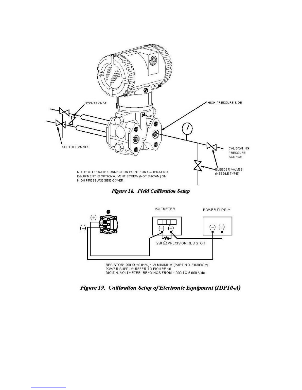
4. Complete the
setup shown
not
being used, remove
the high
using a suitable
opened in Step 1.
in
Figure
pressure side
thread sealant.
12.
the entire vent
of the
transmitter.
screw assembly
Connect
or drain
NOTE
For
vacuum applications, connect
side
of the
transmi
tter.
the
calibrating pressure source
to the
low pressure
5. If
calibrating
Figure
the 4 to 20 mA output
19.
signal, also
connect equipment
as shown
in
[29]
98MANALIDP10AV Rev. A 8/16/11
Page 30
Bench
The bench
out
The input
transmitter as shown.
Calibration Setup
calibration setup requires disconnecting
disconnecting
setup
the
is
shown
process
Vent the
piping,
in
Figure
20. Connect the input piping to the high
low pressure side
refer
to the
[30]
the
“Field
of the
process
transmi
piping. For
Calibration
tter.
calibration
Setup”
procedure.
pressure side
98MANALIDP10AV Rev. A 8/16/11
setup with-
of the
Page 31
NOTE
For
vacuum applications, connect
side
of the
Also
connect
transmi
electronic
tter.
equipment
the
calibrating pressure source
as shown
in
Figure
19.
to the
low pressure
G
eneral
Calibration
1.
Each transmitter
One
benefit
differential pressure
applied differential pressure
This digital value
calibrated
over
the
2. The internal
and converted to a 4 to 20 mA or 1 to 5 VDC analog output signal.
of
this process is
or not.
calibrated
digital value
Setup
is
factory characterized over
within
of
differential pressure
Calibration assures
range.
its range limits regardless
of
that
every transmitter
is
measured
that the
differential pressure
[31]
its full rated
can
and
converted
is
always available whether
transmitter
can be
differential pressure
measure
of the
calibrated range.
into an internal
rated
displayed
range.
any applied
The
digital
the
transmitter
accuracy
on the
98MANALIDP10AV Rev. A 8/16/11
value.
is
is achieved
local display,
Page 32

3.
Each
transmitter
This
calibration optimizes
over
that
range.
limit (URL).
is factory calibrated
the
accuracy
If no
range is specified,
to
either a specified
of the internal
the
default range is zero
or a
default calibrated
digital value
to the sensor upper
range.
of differential
pressure
range
4. There
Notes for Electronic Version
The
transmitter
Range Value
and
re-ranging
1. Defining the
is
an independent trim on the
allows for slight adjustment of the 4 and 20 mA or 1 and 5 VDC outputs. This
compensates for any slight difference that exists between the transmitter output and
an
external
The trim
does
measured pressu
The trim can be done with or without
(URV).
When either CAL LRV or CAL URV is initiated from the
transmitter expects
pressed
This function
a
calibration based
values entered
This function also sets the 4 and 20 mA (1 and 5 VDC for IDP10-V) output points;
that is, the 4 and 20 mA (1 and 5 VDC for IDP10-V) points correspond to the values
of LRV and URV in the database.
reference device
does
not
affect
not
affect
the internal
re.
data
base has configurable values
These stored values
without pressure.
Calibrated
that the
is
equal
to the
trims
on the
for
LRV
which is
the
Range
LRV
the internal
application
and URV in the transmitter database.
digital-to-analog conversion stage.
measuring
calibration
digital value
are
used
differential pressure applied
or URV
value
digital value
of
the output.
or the
of
pressure applied
for both
for two
re-ranging
pressure
-A
respectively.
accurate differential pressures
or the
and
of
-V
Lower Range value (LRV)
functions; defining
differential pressure;
This trim
of the
transmitter
transmission
to the transmitter.
or
display
and
and Upper
the
calibrated
pushbuttons,
at the time the button is
the
that is, it
equal to the
performs
of
range
If the transmitter is configured for reverse range, the 20 and 4 mA (5 and 1 VDC for
2.
IDP10-V) points correspond to the LRV and URV respectively.
Re-ranging
Since
differential pressure
the 4 and 20 mA (1 and 5 VDC for IDP10-V) output points can be assigned to any
range values (within the span and range limits) without application of pressure.
The
URV.
Re-ranging does
of the internal
If the
may
Without the
the
transmitter continually determines
re-ranging
re-ranged LRV
not be
as accurate as
Application
from the
function
not
digital value
is accomplished
affect
and URV
when they
of
Pressure
lower range
the
calibration
of
differential pressure over a specific calibrated
are
not within the
are
[32]
an internal
limit
(LRL)
by
entering
of the
transmitter;
within the
digital value
to the upper
new
database values
that
calibrated range,
calibrated
range.
98MANALIDP10AV Rev. A 8/16/11
range
is,
of the measured
limit (URL),
for
LRV
and
the optimization
range.
the measured
values
Page 33

3. LCD Indicator
The
display
the
calibrated range
transmitter and
If the
measured differential pressure
URV
values
blinks
to
indicate
at
either
the
can
show any measured differential pressure
display).
in the
low
or high
and the
database,
that the
values
The
of
display
is
the
display shows
measurement is
over-range
limit
LRV
and URV (within the
can
also
outside
the
out of
respectively
in
selected units regardless
limits
be 0 to 100 percent.
range established
the
measurement
range.
The current
but the
but
display continually show
of the
by the
also
continually
signal is
LRV
and
saturated
of
s
the pressure.
Custom
transmitter is
4. Zeroing the Transmitter
Zeroing
When the
transmitter may have
differential pressure applied
produces
have
For
100
to
differential pressure
the other hand, if the
process
can be
flow units
does
transmitter
the
for
display, including
in
square
not
root mode.
affect
is
either
the span
zeroed
.
to
LRV differential pressure applied
(CAL AT0). If
same result. However,
0 to 100 percent, are
compensate
using a zero-based range,
if the
range is
for
installed
not
used
position
(CAL LRV) or zero
zero-based,
it
both methods available.
example, consider a differential pressure transmitter having a range
psig.
If it is not
bypass
the high and
line yet (or the high and
zeroed while
feasible
to vent the transmitter to
low sides
of 50 psi is
applied
transmitter has
open to
atmosphere
for
zeroing),
by
been
low sides
it
using
installed
can be
(or
bypassed)
atmosphere
may
be
zeroed while
the CAL LRV function. On
but there is no
connected
by
by a
bypass valve), i
using
the CAL AT0
when the
effect,
the
either method
is advantageous
for
of 50 to
zeroing
(or
the LRV
pressure
in the
t
to
function.
a. Zeroing with
Before using
equal
When
LRV Pressure Applied
this
zeroing
to the
value
zeroing
of
LRV stored
the
transmitter,
(CAL LRV)
function,
in the
the internal
apply a differential pressure
transmitter database
digital value
.
of
differential pressure
to the
transmi
tte
r
is
trimmed to be equal to the value of LRV stored in the database and the mA
(VDC for IDP10-V) output set to 4 mA (1 VDC for IDP10-V).
If
zeroing is
value
in the
the difference in the values but the output is still set at 4 mA (1 VDC for IDP10V).
The CAL LRV (and CAL URV) function
transmitter
the
LRV
b.
Zeroing
Make
and URV.
with Zero
sure
transmitter
done when the
database,
for a
the internal
specific range
Pressure Applied
that the
applied differential pressure is
to atmosphere.
applied differential pressure is different
digital value
with known input
of
differential pressure is biased
should
be
used
when
differential pressures applied
(CAL AT0)
at
zero.
This
means venting
[33]
98MANALIDP10AV Rev. A 8/16/11
from the LRV
by
calibrating
a
for
the
Page 34
When
zeroing
trimmed to be equal to zero and the mA output (VDC for IDP10-V) set to an
appropriate value such that the mA output (VDC for IDP10-V) is a nominal 4 mA
(1 VDC for IDP10-V) when the LRV pressure is applied later.
the
transmitter,
the
internal digital value
of the
differential pressure is
Calibration and
The
local display, as shown
numeric display (4-digit
play.
The
display provides local
ing
calibration
You
can
access these operations
menu
restore your
by
is
made (from normal
prior
going
to Cancel and
NOTE
During
For
calibration
example, changing
(EGU) to Percent by
entire data
configuration
Configuration Using the Local Display
in
when a
and
configuration,
calibration
pressing
or
configuration, a single change
from
default.
base
or use the Cancel
and begin again.
Figure
21,
has
minus sign is used);
indication of
and
testing
by
means
operating
or
configuration,
of a
mode) by
the Enter button.
linear
to
square
For this
feature
two
lines
of
information.
the
lower line is
measurement information
the
display via
multi-level
pressing
a 2-button (Next and
menu
system.
the Next button.
The upper line
an 7-digit
and a
alphanumeric
means
Enter) keypa
Entry to the Mode
You
can
is
a 5-digit
dis-
for perform-
Select
exit this
menu,
and return to the normal operating mode at any time
may
root mode
reason,
to
restore
affect several
also changes
if an entry is Entered in error,
the transmitter to its
parameters.
the
engineering
starting
units
re-examine
d.
the
[34]
98MANALIDP10AV Rev. A 8/16/11
Page 35
[35]
98MANALIDP10AV Rev. A 8/16/11
Page 36

ADJ 4MA causes the following four submenus
∆∆
A
4mA
∇∇
A
4mA
∆
A
4mA
∇
ADJ 20MA causes the following four submenus
A
20mA
∆∆
∇∇
∆
A
20mA
∇
Calibration
To
access
the
Calibration
play reads
CALIB, the
ing the Enter button. The
calibrate
the
items shown
(For IDP10-V, substitute 1 volt for 4 mA and 5 volts for 20 mA.)
Item
mode (from normal
first
item on the menu.
display will show
operating
Acknowledge
the
first
item in the
mode),
in Table 2.
Table 2. Calibration Menu
Desc
press
your
choice
Calibration
ription
the Next button. The dis-
of
this selection
menu.
You
by pre
can then
ss-
CAL AT0
CAL LRV
CAL URV
ADJ 4MA
ADJ20MA
A
4mA
Calibrate with zero pressure.
Calibrate with pressure at 0% of transmitter range (LRV)
Calibrate with pressure at 100% of transmitter range (URV)
Adjust nominal 4 mA output
Adjust nominal 20 mA output
Increase 4 mA output by large step
Decrease 4 mA output by large step
Increase 4 mA output by small step
Decrease 4 mA output by small step
Increase 20 mA output by large step
A
A
20mA
20mA
Decrease 20 mA output by large step
Increase 20 mA output by small step
Decrease 20 mA output by small step
For IDP10-V, substitute 1 volt for 4 mA and 5 volts for 20 mA.
NOTE
is
not
1. It
is
match
and “span”
between
a plant
readings
necessary
requirement
operations
the
to
use
to make the 4 and 20 mA output
on certain plant
done result in a
transmitter
the ADJ4MA or ADJ20MA menu
values exactly
calibration
mA output and the
equipment and the
small
but
unacceptable difference
test
equipment mA readout
selections unless
“zero”
there
values.
2. The IDP10-A
pressure.
transmitter
See
EGU LRV and EGU URV in
can be
re-ranged
without the
Figure
24.
application
of
Proceed
to specify your selection per Figure 23. At any point in the calibration you may
restore your prior
calibration.
to
calibrate
your
transmitter
calibration
by
using
the Next
key
to
select
your item and the Enter key
and return to the online mode or Save your new
Cancel
,
[36]
98MANALIDP10AV Rev. A 8/16/11
Page 37
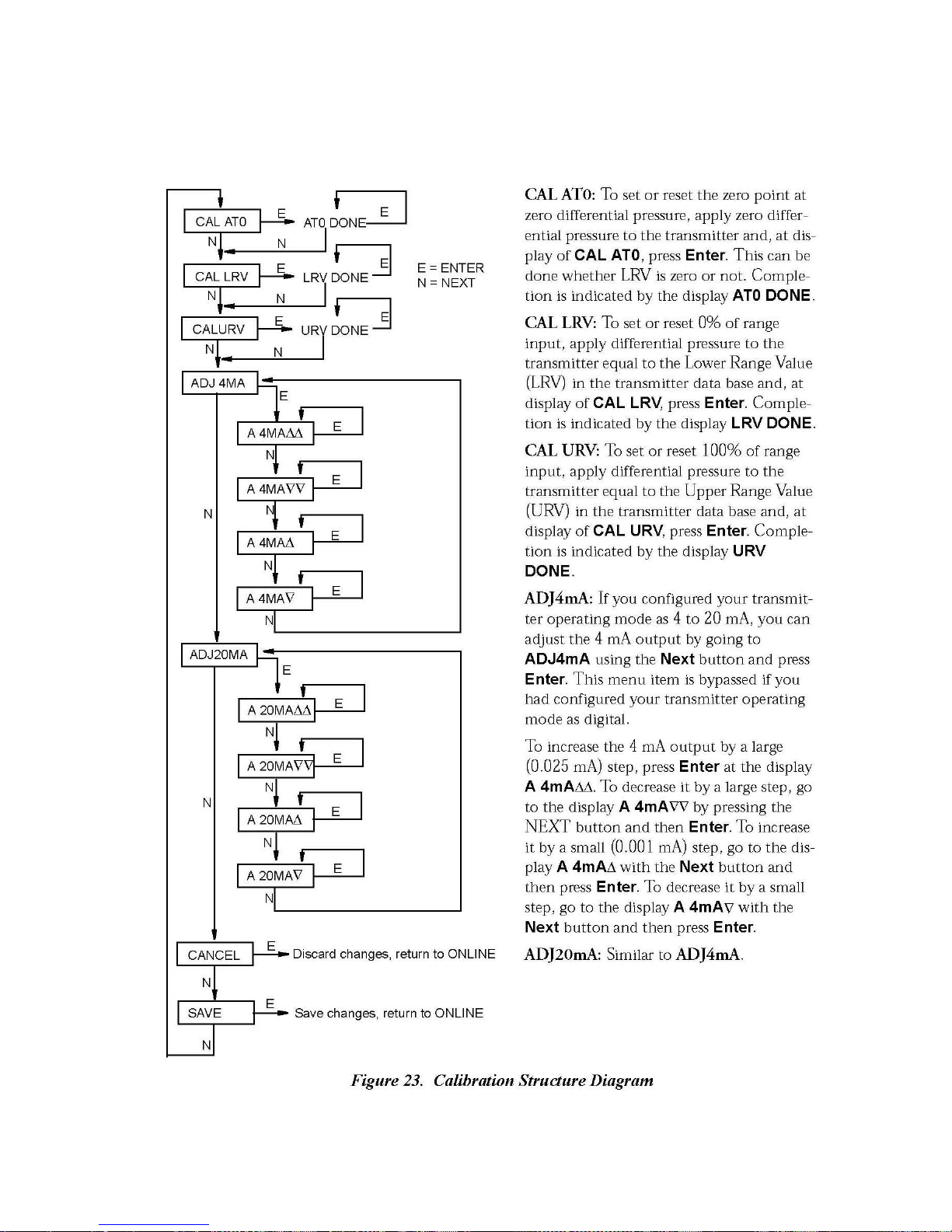
IDP10-A and IDP10-V Calibration
[37]
98MANALIDP10AV Rev. A 8/16/11
Page 38

Item
Description
Initial
Factory
Config
uration(a)
EX ZERO
External zero; enable or disable
Disable
Zero
An
local “re-zeroing”
cover.
from
On the IDP10-A or IDP10-V transmitter, the external zero button does a CAL AT0
calibration (at zero differential pressure). To use this feature:
Adjustment
optional
entering
1. Unlatch the
2. On the IDP10-A or IDP10-V transmitter, press the button with zero differential
3. The
4. If
5.
external zero adjustment mechanism
of the
The
mechanism is magnetically activated
the
enclosure.
external zero
that the
Do not push the button in with the
pressure applied to the transmitter or the bypass valve open and the transmitter at
a
non-zero
not
additional re-zeroing
Re-latch
accidental pressing
while
screwdriver slot lines
static pressure.
display indicates
online, the
the
doing this.
display reads
external zero
Using
transmitter
Zeroing
button by turning it 90 ° in a
ZEROED. If EX ZERO
is
required,
button by turning it 90 ° in a
of the button. Do not
External
output without
is accomplished
up with the two
screwdriver while
BAD KEY.
wait 20
Zero Button
in the
electronics housing (see Figure
having
through the
seconds
push
to
when the
holes
is disabled,
and
the button in with the screwdriver
remove
housing wall
in the
doing this.
clockwise direction
the
electronics
to
prevent moistur
external zero
counterclockwise direction
face
or the
repeat
Step 2.
button
of the
adjacent
transmitter is
to prevent
21) allow
compartment
is depresse
part.
s
e
d.
so
Configuration
You
can
access
enter Calibration mode. Entry to the Mode
by pressing
Next button
of this
Configuration menu. You can then configure items shown in Table 3 for the IDP10-A or
IDP10-V transmitter. The initial
selection
OUT DIR Output direction; forward or reverse Forward
OUTMODE Output; linear or type of square root Linear
OUTFAIL Fail mode output; low or high High
DAMPING Damping; none, 2-, 4-, or 8-seconds None
the
Configuration
the Next button. The
again
to get to the
by
pressing
Table 3. IDP10-A or IDP10-V Configuration Menu
second
the Enter button. The
mode by the
display reads
item on the menu, CONFIG.
factory configuration
same multi-level
Select
menu is made (from normal
CALIB, the
display will show
is
menu
first
item on the menu.
also given
system
the
in
that
Acknowledge
first
item in the
these
tables
was used
operating
Press
your
.
to
mode)
the
choice
[38]
98MANALIDP10AV Rev. A 8/16/11
Page 39

(b)
Item
Table 3. IDP10-A or IDP10-V Configuration Menu (Continued)
Desc
ription
Initial Factory
Configuration
(a)
EGU SEL
EGU LRV
EGU URV
DSP URV
(c)
Engineering
Select
from list if
enter custom units if
(b)
Set
Lower Range Value
Set Upper
User defined
units for
calibrated range
linear
square
Range Value
Upper
Range Value
and
displa
y:
Per
mode.
Choose Percent
root mode.
or
for Linear;
Percent
(LRV) Per
(URV) Per
for display
Per
Sales Orde
for Sq Rt
Sales Or
Sales Or
der
der
Sales Order
r
(a) Default settings.
configuration is custom
(b) This parameter
(c) This parameter is
If optional
per order.
is only
only
shown
shown
feature
“–C2” is
specified,
the initial
when OUTMODE is LINEAR.
when OUTMODE
is
one of the
factory
square
root selections.
Proceed
to
configure your transmitter by using
the Next
key
to
select your
item and the Enter
key to specify your selection per Figure 24 (IDP10-A or IDP10-V). At any point in
the
configuration
changes
.
you
may
Cancel your
changes
and return to the online mode or Save your
[39]
98MANALIDP10AV Rev. A 8/16/11
Page 40
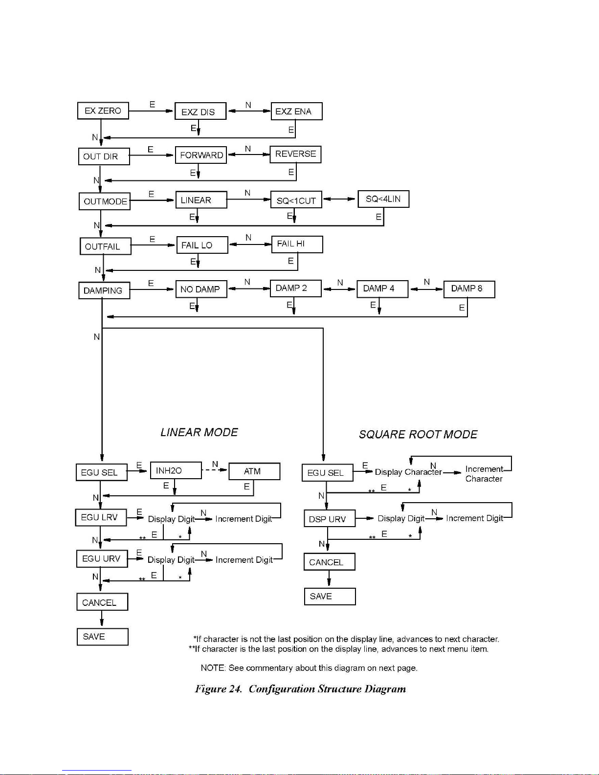
IDP10-A and IDP10-V Configuration
[40]
98MANALIDP10AV Rev. A 8/16/11
Page 41

Commentary on
In
general, use
EX
ZERO: The
for
additional security.
press
Enter.
Figure 24
the Next button to
External
Use
the Next button to
Zero
To
configure this feature,
select
an item and Enter button to
feature allows
select
specify
the optional
external zero
pushbutton to be disabled
go to EX ZERO with the Next button and
EXZ DIS or EXZ ENA and
a selection.
press
Enter.
OUT DIR: To
configure
the Output Direction, go to OUT DIR with the Next button and pre
ss
Enter.. Use the Next button to select FORWARD (4-20 mA for IDP10-A or 1-5 VDC for
IDP10-V) or REVERSE (20-4 mA for IDP10-A or 5-1 VDC for IDP10-V) and press Enter..
OUTMODE: To
and
press
Enter.
below 1% of
4% of
calibrated pressure range)
configure
Use
the mode of the output, go to OUTMODE with the Next button
the Next button to
calibrated pressure range),
and
press
select
LINEAR, SQ<1CUT
or SQ<4LIN
Enter.
(square
(square
root with dual
root with
cutoff
slope linear below
NOTE
If you
configure
to establish
as one of the
wish
the output and
OUTMODE
the
pressure LRV
square
display
as
LINEAR and
and URV. Then go back and
root mode
to be in
selections
square
follow
and
follow
root, it is
the
Linear
the
necessary
Mode path in
configure
Square
Root Mode path
to first
Figure
24
OUTMODE
.
OUTFAIL: The Outfail
figure
the
fail
mode output, go to OUTFAIL with the Next button and
Next button to
DAMPING: To
Enter.
EGU
Use
SEL:
select
configure additional damping,
the Next button to
To
configure engineering units
with the Next button and
remainder
If OUTMODE
of the
configuration takes
was configured as
feature provides
high or
FAIL LO or FAIL HI and
go to DAMPING with the Next button and press
select
NO DAMP, DAMP 2, DAMP 4, or DAMP 8 and
for your
press
Enter. Depending on how OUTMODE is
one of two paths
LINEAR,
use
low
output with
press
Enter.
certain malfunctions.
calibrated range
.
the Next button to
and
select
To con-
press
Enter.
display,
configured,
Use
go to EGU SEL
the
one of the following
the
press
Enter.
units: INH2O, INHG, FTH2O, MMH2O, MMHG, PSI, BAR, MBAR, G/CM2, KG/CM2,
PA, KPA, MPA, TORR, or ATM and
If OUTMODE
unit up to
Use
the Next button to step through the
first character,
Repeat this
seven characters, use blanks
space,
the
EGU
LRV:
to toggle between a space
the
library
is entered and the
digit. Then
was configured as
seven characters
then
press
Enter.
procedure
until you
display advances
To
configure
the
or a
of
numerical characters
second
use
the Next button to
digit
SQ<1CUT or SQ<4LIN, you can
in length. The
Your selection is entered
have created
for the
to DSP URV.
LRV, press
minus
flashes. Repeat
Enter.
EGU
URV: Similar
to EGU
LRV immediately
press
Enter. The
display shows
library
of
characters (see
display advances
Percent with the
and the
your new unit name. If the unit name
remaining spaces.
When you
Enter at the prompt EGU LRV.
and
press
to
move
select
Enter. Then
the
desired first
this
the
decimal
procedure
use
digit, and
until you
point to
above.
[41]
to EGU LRV.
specify
any custom display
first character flashing
Table 4) to
select
the desired
second character flashes.
has less
have configured
the Next button to
press
have
its desired location
98MANALIDP10AV Rev. A 8/16/11
the
Use
the Next button
step
Enter.
Your selection
entered your
and
than
seventh
through
last
press
.
Page 42

DSP URV: To
DSP URV.
use the Next button to
digit, and
procedure until
point to its
configure
Use
the Next button to
press
Enter.
you
have
desired location
the
display
step
through the
Your selection is entered
entered your
and
URV in the units
toggle between a space
library
last
digit. Then
press
Enter.
specified, press
or a minus and
of
numerical characters
and the
second
use
digit
the next button to
Enter at the prompt
press
Enter. Then
to
select
the
desired first
flashes. Repeat
move
this
the
decimal
Re-ranging an
The IDP10-A and IDP10-V Transmitter can be re-ranged without application of pressure. To
do this in linear mode, just reconfigure EGU LRV and EGU URV. To re-range the transmitter
being used in Square Root mode, perform the following procedure:
1. In
2. Then
3.
4. Set OUTMODE
5. Change EGU SEL and DSP URV if required.
6.
When OUTMODE
entering EGU LRV and EGU URV in
Configuration,
configure
if necessary.
Save
this configuration.
Save
this configuration.
NOTE
IDP10-A
set OUTMODE to LINEAR. This is a
EGU LRV and EGU URV,
back
to your
is set
in
square
and IDP10-V Transmitter
first changing
choice
of
square
root mode, the last
linear
root mode.
mode
is always
temporary
the units in EGU SEL
saved pressure range set
maintained.
state.
by
[42]
98MANALIDP10AV Rev. A 8/16/11
Page 43

IDP10-A and IDP10-V Character Lists
Table 4. Alphanumeric Character List
Ch
aracters
space (shown as )
*
+
–
/
0 through 9
<
>
A
through Z (upper
[
\
]
- (underscore)
Table 5. Numeric Character List
Ch
–
aracters
0 through 9
case
)
[43]
98MANALIDP10AV Rev. A 8/16/11
Page 44
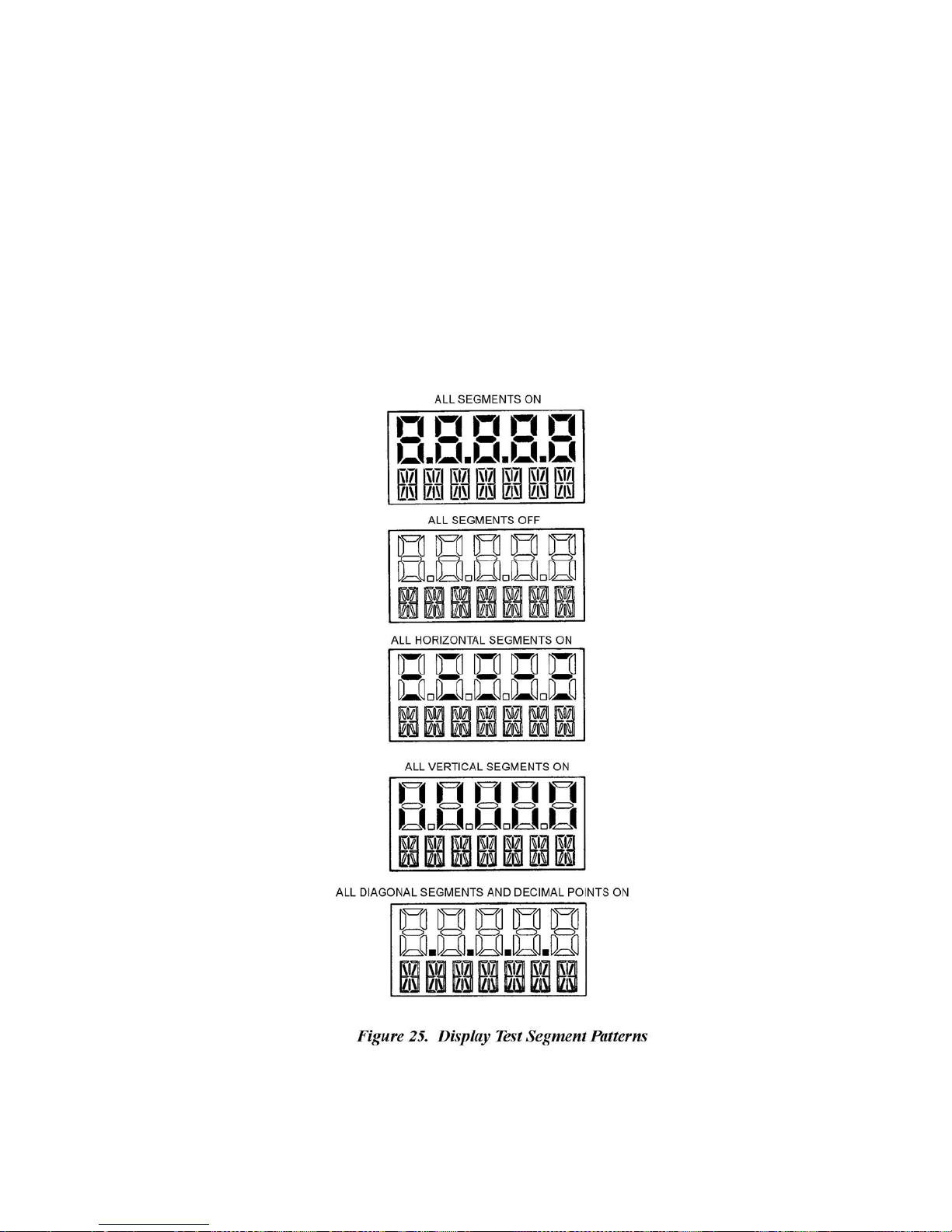
Testing
You
can
Calibration
operating
menu.
Acknowledge
first
test
ton.
pressed, the
a
bout
shown
the Display
access
the Test
and
Configuration
mode) by
Press
the Next button three
your
segment
You
can abort the test at any time by
display automatically steps
five seconds
in
Figure
25.
Display
pressing
choice
pattern.
at
each
mode by the
mode. Entry to the Mode
the Next button. The
of
this selection
You
can
pattern and then return to the Online mode. The
same multi-level
display reads
times
to get to the fourth item on the menu, TST DSP.
by
step
through the
through the
pressing
pressing
the Enter button. The
five patterns
the Enter button. If neither button
five patterns
menu
Select
systems was used
menu is made (from normal
CALIB, the
by
repeated use
in the order
to enter
first
item on the
display shows
of the Next but-
is
shown, pausing
five
patterns are
the
for
[44]
98MANALIDP10AV Rev. A 8/16/11
Page 45

Error Messages
Table 6. Error Messages
Message
I
nterpret
ation
OVR RNG
UND
RNG
Normalized calculation result greater
a.
Overrange
b.
Bad
span
c.
Bad sensor connection; check electronics
d.
Defective
Normalized calculation result greater
a.
Underrange
b.
Bad zero calibration; recalibrate
c.
Bad sensor connection; check electronics
d.
Defective
FDB ERR CRC error
a.
Incorrect user database; replace
b.
Bad sensor connection; check electronics
c.
Defective
UDB ERR CRC error
a.
Incorrect user database; reconfigure/recalibrate
b.
Bad sensor connection; check electronics
c.
Defective
BAD
IN1
Normalized raw pressure
a.
Extreme overrange
b.
Bad calibration; recalibrate
c.
Bad sensor connection; check electronics
d.
Defective
input;
correct
input condition.
calibration; recalibrate span
or
damaged sensor; replace
input;
or
detected
or
detected
or
correct
input condition.
damaged sensor; Replace sensor
in
Factory Database
damaged sensor; replace se
in
User Database
damaged sensor; replace se
input
outside
or
underrange
transmitter.
or
damaged sensor; replace
than 2%
above calibrated span.
.
module to
sensor
connection.
sensor.
than 2%
below calibrated
zero.
zero.
module to
sensor
connection.
.
on startup.
sensor.
module to sensor.
nsor.
on star
tup
.
transmitter.
module to sensor.
nsor.
of limits.
input; Correct input condition.
module to sensor.
sensor.
BAD IN
BAD KEY
3
Normalized raw temperature
a.
Bad sensor connection; check electronics
b.
Defective
Invalid keypress
a.
Pressing External
or
damaged sensor; replace
detected
Zero button with EX ZERO
input
outside
Online.
b.
Pressing
c.
Pressing
has
LOL
IMIT Calibration adjustment has reached lower limit.
a. Improper
b.
Bad
HIL
IMIT Calibration adjustment has reached upper limit.
a. Improper
b.
Bad
Enter when transmitter is
Next or Enter
while
cleared.
calibration setup; correct
D/A
converter; replace electronics
calibration
D/A
converter; Replace electronics
setup; Correct setup.
WAIT
[45]
of limits.
module to sensor.
sensor.
Online.
is displayed;
setup.
module.
module.
disabled
try
or
transmitter
again after
98MANALIDP10AV Rev. A 8/16/11
WAIT
not
messag
e
Page 46

CAL AT0, CAL LRV
EX ZERO
CAL URV
EGU LRV
Table 6. Error Messages (Continued)
Message Interpretation
BADZERO Recalculation of offset during
of
range
value.
a.
Applied pressure
b. Improper
calibration setup.
too high during operation.
BADSPAN Recalculation of slope during
operation resulted in out of range value.
, or
resulted in out
a. Applied pressure too low during CAL URV operation.
b. Improper calibration setup.
BAD LRV Entered value for
is outside sensor limits.
BAD URV Entered value for EGU URV is outside sensor limits.
BAD RNG Recalculation of turndown during EGU LRV or EGU URV resulted in out
of range value. Entered values for EGU LRV and/or EGU URV were either
too close together or too far apart
.
RNG>EGU Recalculation of display value for EGU LRV or EGU URV resulted in out of range
value. Selection
of
(linear)
EGU units
caused display
to overflow.
LRVNOT0 Attempting mode change from LINEAR to SQ<1CUT or SQ<4LIN when
EGU LRV is not 0.0.
[46]
98MANALIDP10AV Rev. A 8/16/11
Page 47

4. Maintenance
!
DANGER
For
nonintrinsically safe installations,
hazardous area, deenergize transmitters before
Failure
or death.
to
comply
with
this warning could result
to
prevent
a potential
you
remove
in an
explosion
threaded
in a
housing
Division
covers.
explosion causing severe
1
injury
Parts Re
Parts replacement
assembly,
and its options, contact Viatran.
placement
is
generally
terminal
block assembly,
Replacing
To
replace
1. Turn
2.
3.
The
Screw
cover
Remove
that
housing.
!
electronics
the
the
electronics
off
transmitter
in
cover lock
by rotating it counterclockwise.
the
electronics
secure
CAUTION
it to the
Then pull the module out of the housing.
module is “one
mechanically connected
power cable,
NOT
exceed
and in
the
4. Unplug
location
all cable connectors
of
each cable,
limited to the
and
Electronics
module
some cases, a cable
slack available
assembly, proceed as follows:
power
(if
source.
present)
module from the
housing. These screws are located towards
assembly”
to
topworks
in
from the rear of the
and
place
electronics
cover O-rings.
Module
and
remove
housing
at
this
with a
these cables
the module on a
flexible
for an optional
when
module
For part
assembly, housing assembly, sensor
numbers relating
the
threaded electronics
by
loosening
point and is
ribbon
electrically
signal cable,
external zero
removing
the
electronics
clean
surface.
to the
compartment
the two
the
captive screws
sides
of the
and
a 2-wire
pushbutton. Do
assembled
module.
module, noting the
trans
mitter
5.
Predetermine
replacement
that
To rotate
secure
NOTE
display, see “Positioning Display”
connector orientation, then, insert the
module.
it to the housing.
6.
Reinstall
the
cover locks
until it
the
housing;
extends
cover
then continue to hand tighten
are
present, align
into the
Replace
onto the
cover serration
the module in the
on
housing
the
by rotating it
serration
to
[47]
page
as
much as
in the
prevent
cable connectors
housing
and tighten the two screws
13.
clockwise
possible
cover
with the
unwanted
into the
until the O-ring contacts
(at
least
1/4 turn). If
lock
and
unscrew
cover
rotation.
98MANALIDP10AV Rev. A 3/23/11
it
Page 48

7. Turn on
The module
NOTE
The
transmitter configuration
configuration settings
Recalibration, however, is
transmitter power source.
replacement procedure
are
retained
recommended.
is now complete.
is
stored
when
in the
replacing
sensor assembly. Therefore,
the
electronics
module.
the
Removing
To
remove
1.
Remove
2.
Remove
using
3.
Reinstall
4.
Reinstall
and
and
reinstall
the
the
caution to
the
the
Reinstalling
the
housing assembly, proceed as follows:
electronics
housing
avoid damaging
housing
electronics
module per
by rotating it
by
reversing
module per
the Housing Assembly
Steps
1 through 4 in the
counterclockwise
the ribbon
cables.
Step 2.
Steps
5 through 7 in the
(when
previous
viewed
previous
procedure.
from the top)
procedure.
Replacing
NOTE
The
transmitter configuration
configuration settings must
Recalibration is
the
Sensor
recommended.
Assembly
is
stored
be
re-entered
in the
after
sensor assembly. Therefore,
replacing
this assembly.
the
To
replace
1.
2.
3.
4.
5.
the
sensor assembly, refer
Remove
Remove
Remove
Replace gaskets
the
electronics
the
housing as described
the
process covers
in
process covers using
Install process covers
increments
to 100 N m (75 lb ft) [66 N m (50 lb ft) for bolt options B1 and D5].
module
and
to
Figure
as described
from
housing
above.
sensor
on new
26 and
above.
by
removing
new
gaskets
sensor.
proceed as
two
.
Torque
follows:
hex
head
cover bolts
bolts.
in
several
even
6.
Reinstall electronics
7.
Pressure
test the
of 150% of the
sides
of the
connections.
sensor
maximum static
process cover/sensor assembly simultaneously
Hold
fluid through the
replace
!
Perform hydrostatic
the gaskets
CAUTION
test with a liquid and
module.
and
pressure
gaskets.
.
process cover assembly
and
overrange pressure
by
applying a hydrostatic
rating
through the proce
for one minute. There should be no
If
leakage occurs,
follow
[48]
retighten the
proper
hydrostatic test pr
cover bolts
pressure
(see page
2) to both
ss
leakage
of the test
per Step 5 or
ocedures.
98MANALIDP10AV Rev. A 3/23/11
Page 49
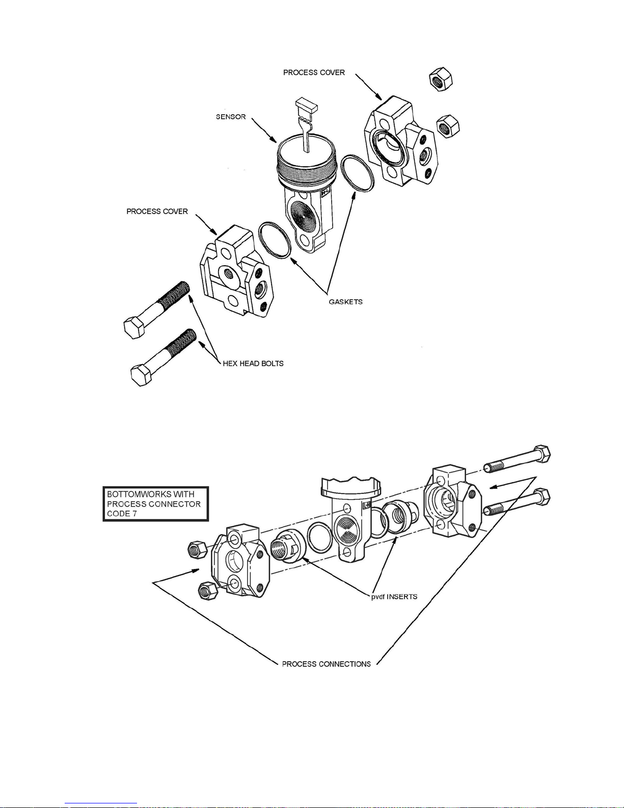
Figure 26. Replacing the Sensor Assembly
Figure 27. Replacing the Sensor Assembly (Code 78/79 pvdf Inserts)
[49]
98MANALIDP10AV Rev. A 3/23/11
Page 50

Replacing
1. Turn
2.
Screw
rotating it counterclockwise.
3.
Remove
4.
Disconnect
5.
Remove
6.
Install
7.
Reconnect
8.
Install
several even
9.
Reinstall
the
cover locks
until it
10. Turn on
the Terminal Block Assembly
off transmitter power
in
cover lock (if present)
the four
socket
the loop
the terminal
new gasket.
the loop
wiring connector
the new terminal
increments.
the
cover
onto the
housing;
then continue to hand tighten
are
present, align
extends
into the
transmitter power source.
source.
and
remove
head
screws securing
wiring connector
block
and the
block
housing
the
and
resinstall
serration
gasket
by rotating it
cover serration
the
from the terminal block.
under it.
to the new terminal block.
the four
as
in the
to
prevent
Field Terminals
compartment
the terminal block.
clockwise
much
cover
unwanted
screws
as possible
to 0.56 N m (5 lb in) in
until the O-ring cont
with the
lock
cover
(at
least
and
rotation.
cover
by
act
1/4 turn). If
unscrew
it
s
Rotating Process Covers
As received,
drain
Sensor cavity venting is provided
However,
with
vertical
Not
the IDP10 Transmitter
connections, regardless
if you did not
mounting by rotating the
NOTE
applicable
when pvdf
of
specify
for Venting
provides sensor cavity
whether
by mounting
this option, you can
inserts
the
transmitter
horizontally
process covers. See Figure
are sp
ecifie
draining without the need for side
is mounted
vertically
or with the optional vent
still achieve venting (instead
28.
d.
or horizontally.
screw
(-V).
of draining)
[50]
98MANALIDP10AV Rev. A 3/23/11
Page 51
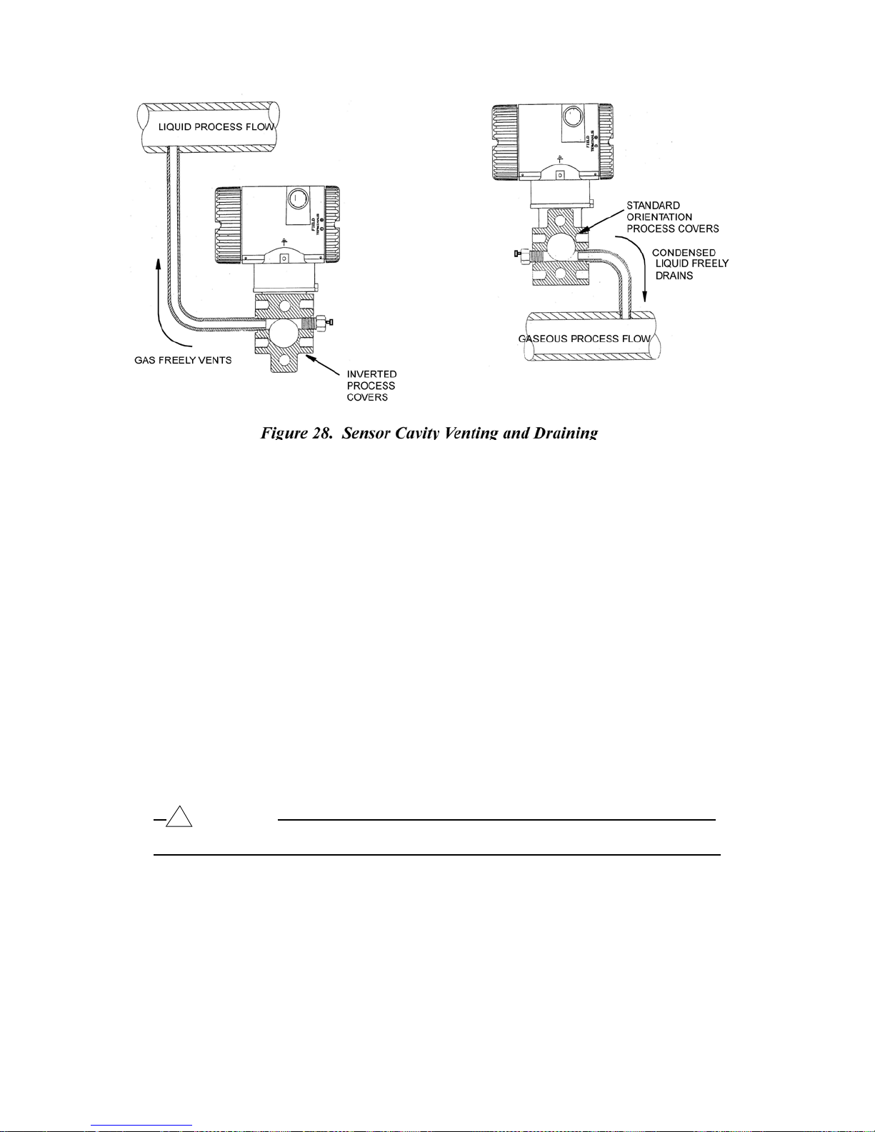
To rotate the
1.
2.
3. Rotate the
4.
process covers, refer
Remove
Replace gaskets
the
process covers
in
process covers.
process covers so
Reinstall process covers
even increments.
spe
cifie
d.
Torque
to
Figure
from
that the
7 and
sensor
longer
by
and bolts. Torque
values
are 66 N m (50 lb ft) when optional 316
proceed as
removing
tab
cover
follows:
two
hex
head bolts.
is
at the bottom.
bolts to 100 N m (75 lb ft) in several
ss
bolts are
5.
Pressure test
of 150% of the
the
process cover/sensor
Hold
pressure
the
gaskets.
the
sensor
maximum static
and
process cover assembly
and
overrange pressure (see page
assembly simultaneously
for one minute. There should be no
If
leakage occurs, retighten
the
cover bolts
by
applying a hydrostatic
2) to both
through the
leakage
per
process conn
of the
Step
4 or
test
pressure
sides
ections.
fluid through
replace
the gasket
of
s
and retest.
!
CAUTION
Perform hydrostatic test
with a liquid and
follow
[51]
proper
hydrostatic
test procedures.
98MANALIDP10AV Rev. A 3/23/11
Page 52

Index
B
Bench Calibration Setup 30
C
Calibration 36
Calibration and Configuration 34
Calibration Notes 32
Calibration Setup 28
Configuration 38
Cover Locks 18
E
Electronics Module, Replacing 47
Error Messages 45
F
Field Calibration Setup 28
Field Terminals 19
Filling System with Seal Liquid 17
G
General Description 6
H
Housing Assembly, Removing and Reinstalling 48
I
Identification 6
Installation 12
M
Maintenance 47
Mounting 12
P
Parts Replacement 47
Piping 15
Positioning Display 17
Positioning Housing 17
Product Safety 10
Product Safety Specifications 10
Putting Transmitter into Operation 22
[52]
98MANALIDP10AV Rev. A 8/16/11
Page 53

R
Reference Documents 6
S
Sensor Assembly, Replacing 48
Specifications 7
T
Taking Transmitter Out of Operation 22
Terminal Block Assembly, Replacing 50
Testing the Display 44
V
Venting, Rotating Process Covers for 50
W
Wiring 18
Z
Zero Adjustment Using External Zero Button 38
Viatran Corporation
3829 Forest Parkway, Suite 500
Wheatfield, NY 14120
Int’l: 1-716-629-3800
Toll Free: 1-800-688-0030
Fax: 1-716-693-9162
www.viatran.com
d/p
Cell,
and I/A
Fluorinert is a trademark
Hastelloy
Monel is a
Polyflo is a trademark
Swagelok
Series are registered trademarks
is a
trademark
trademark
is a
of Inco
of
trademark
of
Minnesota
of
Haynes
Alloys International,
Imperial Eastman Division
of
Crawford Fitting Co.
Mining and
International.
of the Invensys Company.
Manufacturing
Inc.
of
Imperial Clevite
Company.
Incorporated.
[53]
98MANALIDP10AV Rev. A 8/16/11
 Loading...