

Viatran IDP10-A, IDP10-V Installation, Calibration And Operations Manual

I/A Series ® Intelligent
Differential Pressure Transmitters
IDP10-A with 4 to 20 mA Output Signal
IDP10-V with 1 to 5 VDC Output Signal
Installation, Calibration, Configuration, and
3829 Forest Parkway, Suite 500
Wheatfield, NY 14120
Int’l: 1-716-629-3800
Toll Free: 1-800-688-0030
Fax: 1-716-693-9162
www.viatran.com
solutions@viatran.com
Maintenance
[1]
98MANALIDP10AV Rev. A 8/16/11

Table of Contents
Figures ........................................................................................................................................................... 4
Tables ............................................................................................................................................................ 5
1. Introduction ..................................................................................................................................... 6
General Description ......................................................................................................................... 6
Reference Documents...................................................................................................................... 6
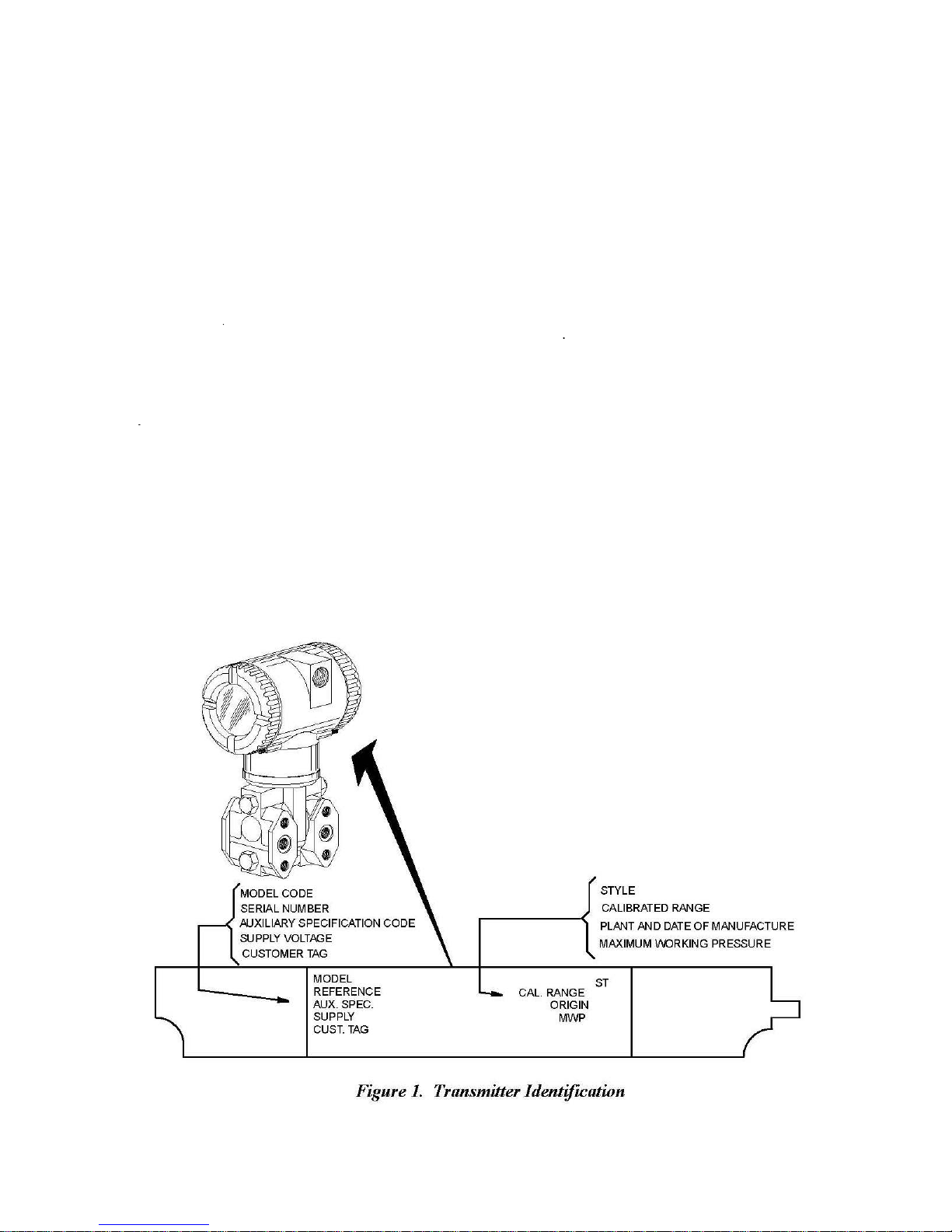
Transmitter Identification ................................................................................................................ 6
Standard Specification ..................................................................................................................... 7
Product Safety Specifications......................................................................................................... 10
2. Installation ..................................................................................................................................... 12
Transmitter Mounting.................................................................................................................... 12
Process Mounted Transmitter .......................................................................................... 13
Pipe or Surface Mounted Transmitter .............................................................................. 13
Installation of Flow Measurement Piping ...................................................................................... 15
Filling System with Seal Liquid ....................................................................................................... 17
Positioning Housing ....................................................................................................................... 17
Positioning Display ......................................................................................................................... 17
Cover Locks .................................................................................................................................... 18
Transmitter Wiring for IDP10-A ..................................................................................................... 18
Accessing Transmitter Field Terminals ............................................................................. 19
Wiring the Transmitter to a Control Loop ........................................................................ 20
Putting Transmitter into Operation ............................................................................................... 22
Taking the Transmitter Out of Operation ...................................................................................... 22
Transmitter Wiring for IDP10-V ..................................................................................................... 23
3-Wire Connection ............................................................................................................ 23
4-Wire Connection ............................................................................................................ 23
Wiring to a Control Loop ................................................................................................... 25
Putting Transmitter into Operation ............................................................................................... 27
Taking the Transmitter Out of Operation ...................................................................................... 27
[2]
98MANALIDP10AV Rev. A 8/16/11

3. Calibration and Configuration ...................................................................................................... 28
Calibration Setup ........................................................................................................................... 28
Field Calibration Setup ................................................................................................................... 28
Bench Calibration Setup................................................................................................................. 30
General Calibration Setup .............................................................................................................. 31
Notes for Electronic Version –A and -V.......................................................................................... 32
Calibration and Configuration Using the Local Display .................................................................. 34
Calibration ......................................................................................................................... 36
IDP10-A and IDP10-V Calibration .................................................................................. 37
Zero Adjustment Using External Zero Button ................................................................... 38
Configuration .................................................................................................................... 38
IDP10-A and IDP10-V Configuration .............................................................................. 40
Re-ranging and IDP10-A or IDP10-V Transmitter .......................................................... 42
IDP10-A and IDP10-V Character Lists ............................................................................ 43
Testing the Display ......................................................................................................................... 44
Error Messages .............................................................................................................................. 45
4. Maintenance.................................................................................................................................. 47
Parts Replacement ......................................................................................................................... 47
Replacing the Electronics Module .................................................................................... 47
Removing and Reinstalling the Housing Assembly ........................................................... 48
Replacing the Sensor Assembly ........................................................................................ 48
Replacing the Terminal Block Assembly ........................................................................... 50
Rotating Process Covers for Venting ............................................................................................. 50
Index ........................................................................................................................................................... 52
[3]
98MANALIDP10AV Rev. A 8/16/11

Figures
1 Transmitter Identification ...................................................................................................................... 6
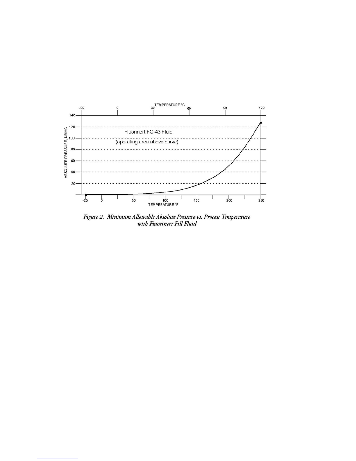
2 Minimum Allowable Absolute Pressure vs. Process Temperature w/Fluorinert Fill Fluid ................... 9
3 Process Mounted Transmitter ............................................................................................................ 13
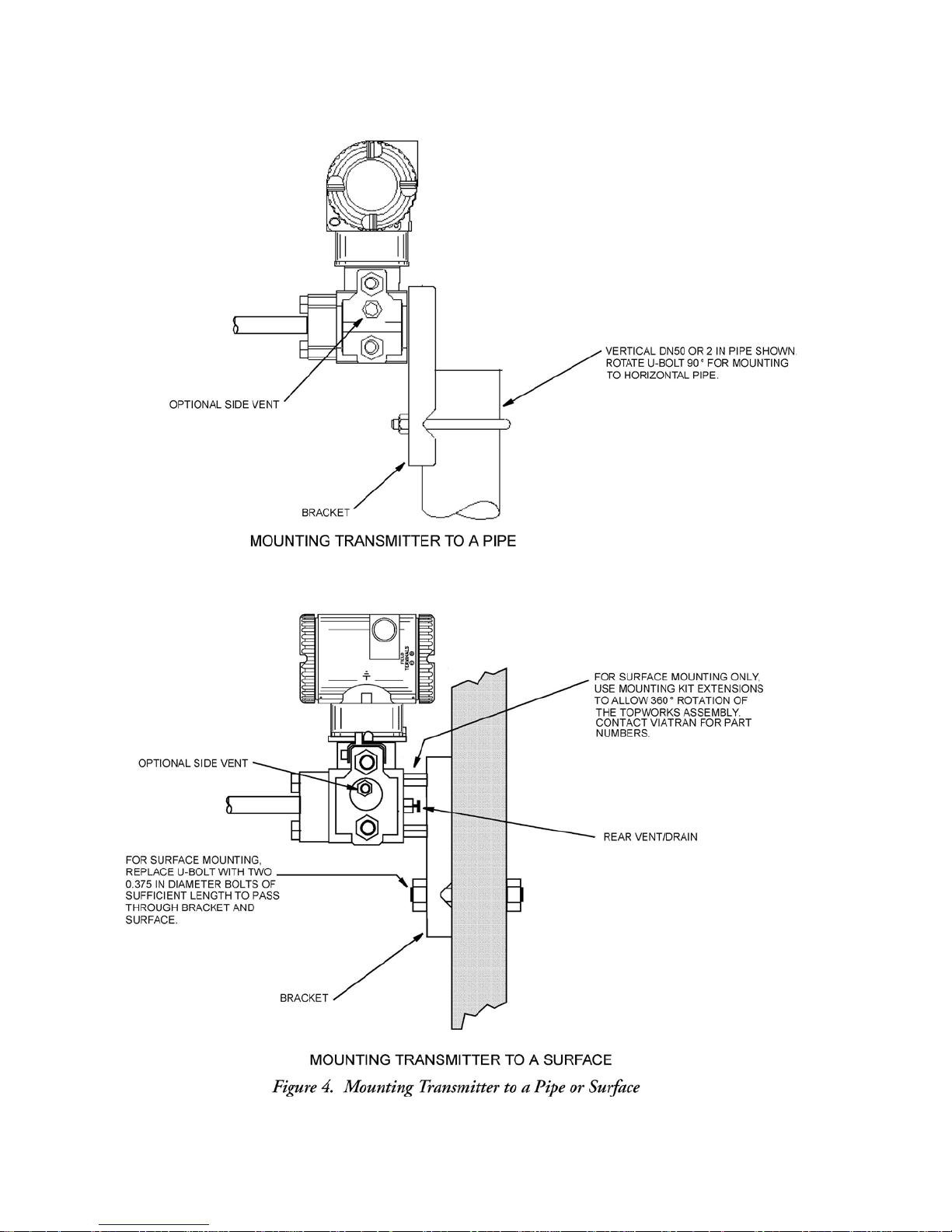
4 Mounting Transmitter to a Pipe or Surface ........................................................................................ 14
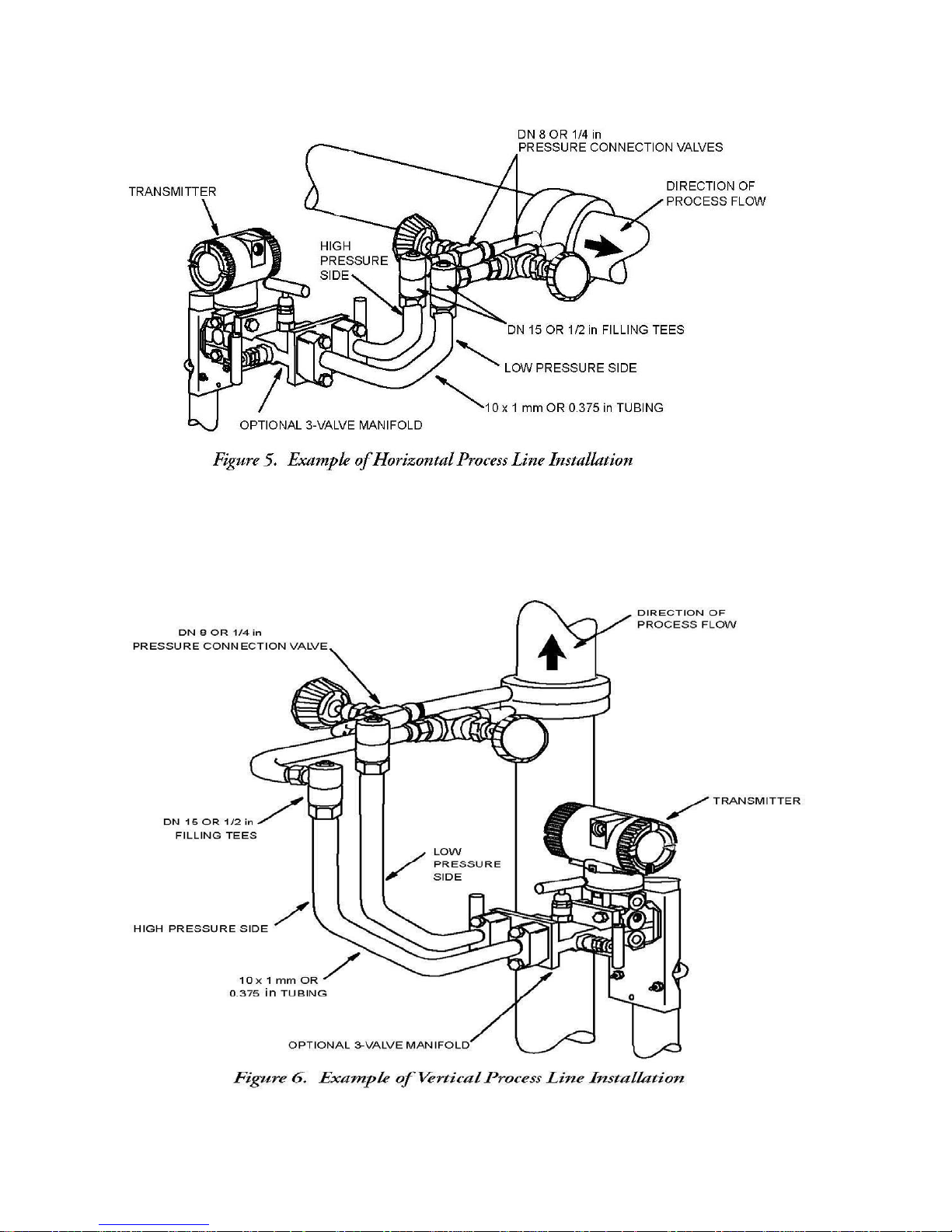
5 Example of Horizontal Process Line Installation ................................................................................. 16
6 Example of Vertical Process Line Installation ..................................................................................... 16
7 Positioning Display .............................................................................................................................. 18
8 Accessing Field Terminals ................................................................................................................... 19
9 Identification of Field Terminals ......................................................................................................... 19
10 Supply Voltage and Loop Load ............................................................................................................ 20
11 Loop Wiring ......................................................................................................................................... 21
12 Wiring Several Transmitters to a Common Power Supply .................................................................. 22
13 Identification of Field Terminals .......................................................................................................... 23
14 Three-Wire Connection ....................................................................................................................... 24
15 Four-Wire Connection ......................................................................................................................... 24
16 Loop Wiring ......................................................................................................................................... 25
17 Wiring Several Transmitters to a Common Power Supply (Four-Wire) .............................................. 26
18 Field Calibration Setup ........................................................................................................................ 30
19 Calibration Setup of Electronic Equipment ......................................................................................... 30
20 Bench Calibration Setup ...................................................................................................................... 31
21 Local display Module ........................................................................................................................... 34
22 Top Level Structure Diagram ............................................................................................................... 35
23 Calibration Structure Diagram ............................................................................................................. 37
24 Configuration Structure System .......................................................................................................... 40
25 Display Test Segment Patterns ............................................................................................................ 44
26 Replacing the Sensor Assembly ........................................................................................................... 49
27 Replacing the Sensor Assembly (Code 78/79 pvdf Inserts) ................................................................. 49
28 Sensor Cavity Venting and Draining .................................................................................................... 51
[4]
98MANALIDP10AV Rev. A 8/16/11

Tables
1 Electrical Safety Specifications .............................................................................................................. 11
2 Calibration Menu ................................................................................................................................... 36
3 IDP10-A and IDP10-V Configuration Menu ........................................................................................... 38
4 Alphanumeric Character List ................................................................................................................. 43
5 Numeric Character List .......................................................................................................................... 43
6 Error Messages ...................................................................................................................................... 45
[5]
98MANALIDP10AV Rev. A 8/16/11
1. Introduction
General
The IDP10-A and IDP10-V Differential Pressure Transmitters measure the difference between two
pressures applied to opposite sides of a silicon strain gauge microsensor within
This microsensor converts differential pressure to a change in
converted to a 4 to 20 mA or 1to 5 VDC signal
of differential pressure. The
the same two wires
The transmitters are often used for measuring fluid flow across a primary device such as an orifice
Description
that
supply power to the transmitter
measurement
the
sensor assembly.
resistance.
proportional
signal for the IDP10-A is transmitted to remote receivers over
to differential pressure or to the square root
electronics.
The resistance change is then
plate, but can also be used for other types of differential pressure measurements such as liquid level,
interface level, or density measurements.
Reference
This document contains descriptions and instructions for transmitter installation, configuration,
calibration, and
Documents
maintenance.
Transmitter
See Figure 1 for transmitter data plate contents. When the transmitter is powered, the firmware
revision is shown on the top line of the display.
Identifica
tion
[6]
98MANALIDP10AV Rev. A 8/16/11

Span Limits
A
Standard
Span and Range Limits
Span Limit
Elevated Zero and
Standard (B7 steel), Option "-B2" (17-4 PS ss), Option
“-D3” or “-D7”(c)
Specifications
Code
0.12 and 7.5 kPa (0.5 and 30 inH2O) -7.5 and +7.5 kPa (-30 and +30 inH2O)
B
C
D
E
Negative values
Positive values indicate
For
applications requiring
range limits
of the
Transmitter Configuration
0.87 and 50 kPa (3.5 and 200 inH2O) -50 and +50 kPa (-200 and +200 inH2O)
7.0 and 210 kPa (28 and 840 inH2O) -210 and +210 kPa (-840 and +840 H2O)
0.07 and 2.1 MPa (10 and 300 psi) -0.21 and +2.1 MPa (-30 and +300 psi)
0.7 and 21 MPa (100 and 3000 psi) -0.21 and +21 MPa (-30 and +3000 psi)
of
differential pressure indicate
high side of
Suppressed Zero
an
transmitter
∆
P
low side of
sensor
at the
elevated
or
suppressed zero,
can not be exceeded.
Bolting
Material
higher
sensor
at the
higher
pressure.
the
maximum span
Maximum Static
Over-range Pressure
Rating(a,e)
MPa
25
Range Limits
∆
P
pressure.
and the upper and
and
Psi
3625
lower
Proof
MPa
100
Pressure
Rating(b)
14500
Psi
Option “B1” (316 ss) or Opti on "-D5"(c) 15 2175 60 8700
Option AS-B7M (B7M) 25 3625 100 14500
Option “-D1”(c) 16 2320 64 9280
Option “-D2”, “-D4”, "-D6", or "-D8"(c,d) 10 1500 40 6000
(a) Either side can be at the higher pressure during over-range.
(b)
Meets ANSI/ISA
(c)-D1 = DIN
-D2 = DIN Double ended
-D3 = DIN
-D4 = DIN Double ended
-D5 = DIN
-D6 = DIN Double ended
-D7 = DIN
-D8 = DIN Double ended
(d)Limited
(e)When
maximum over-range is 2.1 MPa (300 psi) and temperature limits are -7 and +82°C (20 and 180°F).
to
Structure Codes
Standard S82.03-1988.
Single
ended
Single
ended
Single
ended
Single
ended
operating temperatures ranging
NOTE
Static pressure zero shift
zero
output at nominal
!
CAUTION
1.
Exceeding
degrading its
2. The
the
maximum over-range pressure
performance.
transmitter
process cover
process cover
process cover
process cover
process cover
process cover
process cover
process cover
78/79 are
for
all calibrated spans
with M10 bolting.
with M10 bolting
with 7/16 in bolting.
with 7/16 in bolting.
with 7/16 in 316
with 7/16 in 316
with 7/16 in 17-4
with 7/16 in 17-4
from 0 to 60 °C (32 to 140°F)
used (pvdf inserts
operating static pressure.
could be nonfunctional
[7]
ss
bolting.
ss
bolting.
ss
bolting.
ss
bolting.
in the Hi and Lo
can be
eliminated
can
cause damage
after application
side process covers),
by
readjusting
to the transmit
of the proof pressure
the
the
ter
.
98MANALIDP10AV Rev. A 8/16/11

Influence
Operative Limits
Sensor Body Temperature
pvdf Inserts
-7 and +82°C (20 and 180°F)
Electronics
Temperature
With LCD
Display
-40 and +85°C (-40 and +185°F)(a)
Relative Humidity
0 and 100%
Supply Voltage
IDP10-A 11.5 and 42 VDC(b)
Output Load
IDP10-A 0 and 1450 Ohms
Mounting Position
No Limit
Output Signal
4 to 20 mA dc linear, 4 to 20 mA dc square root, or 1 to 5 VDC, software selectable,
locally configurable using pushbuttons on the transmitter.
Zero and Span
Adjustable
moisture sealed pushbutton
housing
Adjust
at the
cover.
ments
transmitter using
assembly allows local resetting
the
local display.
An optional
of
zero
external se
lf-contained
without removing
Field Wiring Reversal
Accidental reversal
limited to 1 A or
1
A will
not
block assembly
less
damage
and
of
field wiring will
by
active
current limiting or loop
the
electronics
module or
external instruments
not
damage
in the loop.
the
sensor
transmitter, provided
the current is
resistance. Sustained currents
but could
damage
the terminal
of
Mounting
The
piping. It can
using
any
“Positioning Housing”
of four
NOTE
Position effect zero
output after installa
Adjustable
The transmitter
setting
an 80% input step
Operative
Pos
ition
transmitter
can be mounted in any orientation. It can be
also
be mounted
an optional mounting
desired
position for
access
on
different positions
shift for all
tion.
Damping
response
of 0.00 (none), 2, 4, or 8,
as defined
Limits
directly
bracket.
to
adjustments, display,
page
13. The
at 90°
increments. See “Positioning Display”
calibrated spans
time is
normally
seconds, whichever is greater,
in
ANSI/ISA
to a
The
vertical
housing
display
1.0
second
S51.1.
supported
or
horizontal
pipe or
can be rotated up to one
can
also
can be
or the
or conduit
be rotated in the
eliminated
connections.
by re
electronically
for a 90%
by the
process
surface mounte
full
turn to
See
housing
on
page
adjusting
adjustab
recovery
to any
13.
zero
le
from
d
Silicone Fill Fluid
Fluorinert Fill Fluid
(a)
Display updates are slowed
(b) 11 V dc with optional
-46 and +121°C (-50 and +250°F)
-29 and +121°C (-20 and +250°F)
IDP10-V 9 to 15.5 VDC
IDP10-V 10 MegOhms
and
readability decreased below temperatures
shorting block (AS code
[8]
of -20 °C (-4°F).
SB-11
98MANALIDP10AV Rev. A 8/16/11
Sensor
Fill Fluid
Silicone
Oil (DC 200), or Fluorinert (FC-43).
Minimum Allowable Absolute Pressure vs. Process Temperature
With
Silicone Fill
With Fluorinert
Fluid
Fill
Fluid
At
full vacuum:
Refer
to
Figure
Up to 121°C (250°F)
2.
Power-Up
Less
electronic
Elec
trical
Field wires
electronics housing. Leads
terminal
environmental,
plugged
Process Connections
IDP10
number of optional
Supply
Time
than 2.0
seconds
damping rate to the
Connections
enter through PG 13.5 or 1/2 NPT threaded
block
with metal plug
transmitters
Current
for output to
final measured variable
terminate under
in the
field
terminal compartment. To maintain RFI/EMI,
and
explosion proof ratings,
(provided), inserted
are
connected
process connectors
reach approximately
screw terminals
unused conduit connection
to
five
to the
process via
.
3.5
mA,
and then at the
value.
full
entrances
turns.
and
on either
washers
side
on the
must
of the
be
a 1/4 NPT thread or any one of a
Power supply must be capable of providing 22 mA current for the IDP10-A and 3 mA
current for the IDP10-V. Ripple of up to 2 V pp (50/60/100/120 Hz) is tolerable, but
instantaneous voltage must remain within specified range.
[9]
98MANALIDP10AV Rev. A 8/16/11

Electrical Ground
The transmitter
compartment and an
To
minimize galvanic corrosion, place
washer
and
(ground) the
trans
Test Po
mitter
ints
The banana plug receptacles (designated CAL) can be used to check transmitter output of
the IDP10-A. Measurements should be 100 to 500 mV dc for 0 to 100% transmitter
output. Refer to Figure 9.
Conne
is equipped
loose washer
shield
at the
.
cti
ons
with an internal ground connection within the
external
ground
on the
external
field enclosure
connection
the
wire lead
ground
at the
or terminal
screw.
base
If
shielded cable
only. Do not ground the
of the
between
field
electronics
the captive
is
used,
shield
at the
wiring
housing.
earth
HHT Terminals
As
the top terminal
PC20, HART Communicator, or IFDC.
Approximate
Without
With
Process
With Optional 316
Process Wetted
Diaphragm:
Covers
and
is blocked, this transmitter does
Mass
Process Connectors
3.5 kg (7.8 lb)
Connectors 4.2 kg (9.2 lb)
ss
Housing Add 1.1 kg (2.4 lb)
Materials
316L
Process Connections:
ss,
Co-Ni-Cr,
Hastelloy
316
ss,
not
communicate
C, gold plated 316L
carbon
steel, Hastelloy
with the HHT, PC10,
ss,
Monel, or tantalum
C, Monel, or
pvdf inserts
Product Safety
To
prevent possible explosions
protection, observe applicable wiring practices. Plug unused
provided
!
To maintain IEC IP66 and NEMA Type 4X protection, the unused conduit opening
must be
T
urn
as
possible
!
DANGER
metal pipe plug,
WARNING
plugged.
covers
until O-ring
(at
Specifications
and to maintain
which engages
In addition, the threaded
contacts housing;
least
1/4 turn).
explosion proof,
dust-ignition proof
conduit
a minimum of
housing covers
five
full threads.
must be
installed.
then continue to hand tighten
[10]
98MANALIDP10AV Rev. A 8/16/11
opening
as
with the
much

C
NOTE
1.
These transmitters have
listed
in Table 1. For
approvals and
2.
Wiring
are
restrictions
provided
certifications,
in the
Testing
Types of
and
CSA intrinsically safe for Class I,
Division 1, Groups A, B, C, and D; Class
II, Division 1, Groups E, F, and G; Class
III, Division 1.
CSA explosion proof for Class I, Division
1, Groups B, C, and D; Dust ignition
proof for Class II, Division 1, Groups E,
F, and G; Class III, Division 1.
CSA for Class I, Division 2, Groups A, B,
C, and D; Class II, Division 2, Groups F
and G; Class III, Division 2.
Area
Laborator
y,
Protection,
Classification
been
detailed
designed
information or status of testing
to meet the
electrical safety description
contact Viatran.
required to maintain
“Transmitter
Wiring”
electrical certification
section
of
this
document on
Table 1. Electrical Safety Specifications
Application Condition
Connect per CD 0629. Temperature
Class T4A at 40°C (104°F) and T3C at
85°C (185°F) maximum ambient.
IDP10-V only.
Temperature Class T6 at 80°C (176°F),
and T5 at 85°C (185°F) maximum
ambient.
Connect to source not exceeding 42.4
V. Temperature Class T6 at 40°C
(104°F) and T4A at 85°C (185°F)
maximum ambient. IDP10-V only.
laboratory
of the transmitter
page
Electrical
s
Design Code
15.
Safety
FM intrinsically safe for C l a s s I, Division
1, Groups A, B, C, and D; Class II,
Division 1, Groups E, F, and G; Class III,
Division 1.
FM explosion proof for Class I, Division
1, Groups B, C, and D; Dust ignition
proof for Class II, Division 1, Groups E,
Connect per CD 0629. Temperature
Class T4A at 40°C (104°F) and T4 at
85°C (185°F) maximum ambient.
IDP10-V only.
Temperature Class T6 at 80°C (176°F),
and T5 at 85°C (185°F) maximum
ambient.
F, and G; Class III, Division 1.
FM nonincendive for Class I, Division 2,
Groups A, B, C, and D; Class II, Division
2, Groups F and G; Class III, Division 2.
Connect to source not exceeding 42.4
V. Temperature Class T6 at 40°C
(104°F) and T4A at 85°C (185°F)
maximum ambient. IDP10-V only.
F
[11]
98MANALIDP10AV Rev. A 8/16/11

2. Installation
The following material provides information and procedures for installing the IDP10-A and
IDP10-V Differential Pressure Cell Transmitter.
!
CAUTION
To
avoid damage
impact
Use a suitable
wrench
NOTE
to the
or
stamping device,
thread
sealant
transmitter sensor,
on the
on all connections.
do not
trans
mit
use
any impact
ter
.
devices, such as
an
Transmitter
The
transmitter
vertical
or
horizontal
NOTE
1. If the transmitter is not
Figure
2. The
transmitter should
draining into the
threaded
connections.
Mounting
can be
supported
pipe or
4,
readjust zero
conduit
by the
surface using
installed
output to
be mounted
field wiring
process
compartment can
piping
the optional mounting
in the
eliminate
so
as shown
vertical
the
that any
position
position zero
moisture condensing
exit
in
Figure
bracket shown
as shown
through one of the two
3, or mounted to a
in
Figure
in
Figure
effect.
or
4.
3 or
[12]
98MANALIDP10AV Rev. A 8/16/11
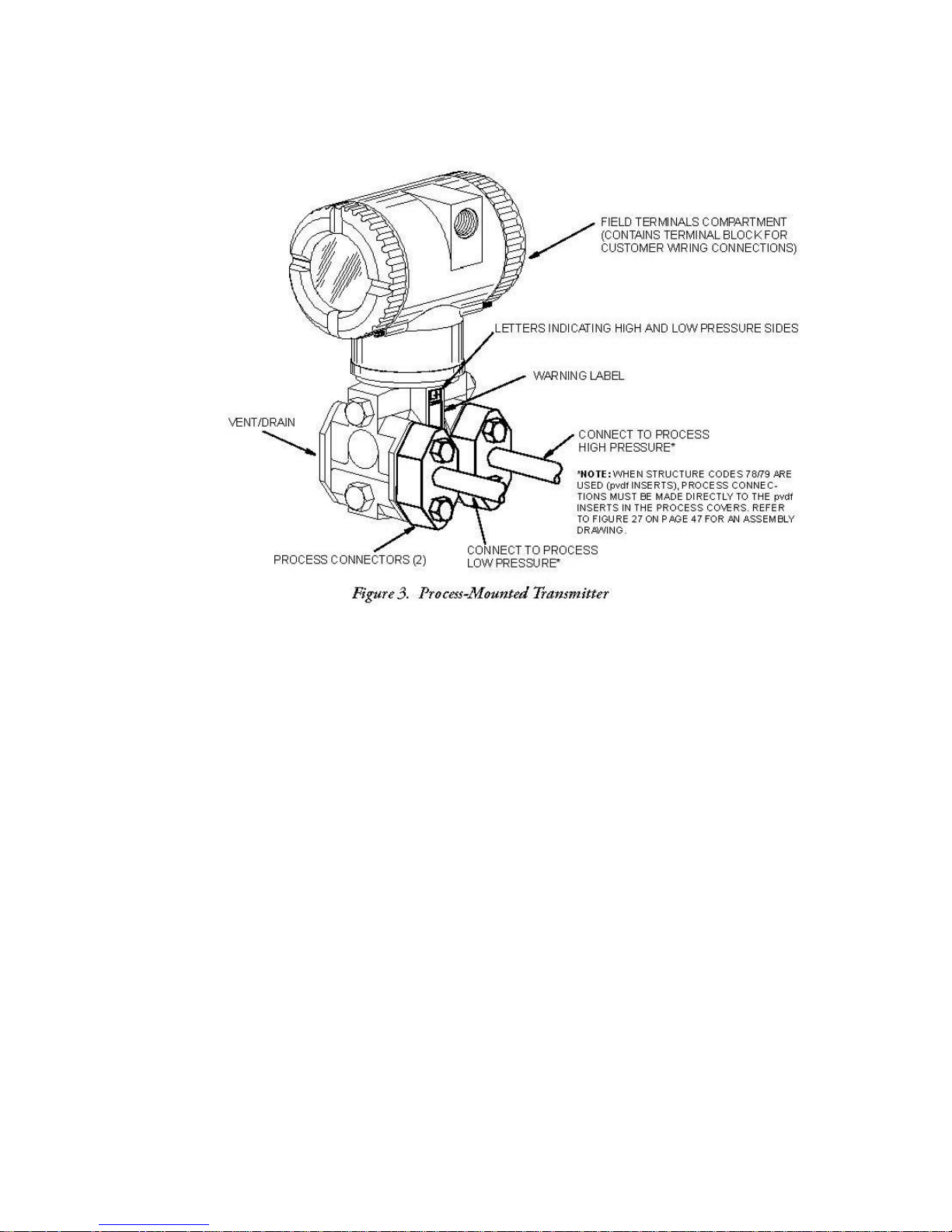
Pr
ocess-
Mo
unted Transmitter
Figure 3 shows
the
transmitter
mounted to and supported by the
process
piping.
Pipe
To mount the
Option -M).
Referring
proor 2-in pipe. To mount to a
Figure
to a
360° rotation of the to
when the
or
Surface Mounted
transmitter
to
Figure
vided.
wall using
Mount the transmitter with mounting
4. The mounting
the U-bolt mounting
transmitter is
to a pipe or
4,
secure
bracket
p-
works assembly.
mounted to a
Transmitter
surface, use
the mounting
horizontal
pipe, turn U-bolt 90 from the position
can
also
holes.
surface as shown
the Optional Mounting Set (Model Code
bracket
be
Mounting kit
This
used
provides
to the
bracket
for
transmitter using
to a
vertical
wall
mounting by
extensions
better
access
in
Figure
4.
the two
or
horizontal,
securing
are
available
to the rear vent/drain
screws
shown
the
bracket
to
allow
DN 50
in
[13]
98MANALIDP10AV Rev. A 8/16/11
[14]
98MANALIDP10AV Rev. A 8/16/11

Installation of Flow
Figure
The
ment,
(for a
If the
lines
transmitter
flow,
(or
ter, the
mounted
tees.
Tighten drain
nector bolts to a torque of 61 N m (45 lb ft).
Note that the high and
the
With
5 and
Figure 6 show typical installations
transmitters
except
seal
liquid).
process fluid being measured
must be
the
lines are filled
water) is
tees
vertically (as shown).
side
of the
medium-viscosity seal liquids
NOTE
1. With a horizontal line,
the line.
of line.
2. With a
3. For liquid or steam
the
4. For gas
the
transmi
5. Viatran recommends the use of snubbers in installations prone to high levels of
flow
are
for
gas flow
filled
must be mounted
added to the
must be at the
plugs
sensor above
vertical
pressure connections
flow
pressure connections
tter should be mounted below the
pulsations.
Measurement
shown below
without a
with a
However,
suitable seal
below
with
water
lines
through the
same elevation (as shown
If a
and optional vent
low pressure sides
the
warning label as shown
with
line,
flow
flow,
without a
seal
with
the
level
of the
seal liquid),
must not
liquid
the
level
to protect the
filling tees.
seal
liquid
screws
of the transmitter
and/or
pressure connections
gas flow
should be upwards.
the
at the pipe.
liquid, the
at the pipe; for gas
long transmitter
without a
transmitter should
pressure connections
and with
come
in
(see procedure
of the
pressure connections
transmitter
in
is
not
to 20 N m (15 lb ft). Tighten the four
transmitter should
pressure
Piping
horizontal
filling tees
contact
To
prevent
Figure
required, elbows
in
Figure
at the pipe
seal
liquid,
be mounted lower than
flow
with a
and
vertical process
in the
with the
in next
from the hot
5) and the
are identified
lines, larger valve sizes should
connections.
transmitter,
section).
unequal
can be
3.
should
connections
be mounted
seal
liquid, the
pipes.
at the pipe
lines
at the pipe. With stea
steam.
heads
transmitter
by an L-H
be at the side of
(usual
to the
In such a
used
should be at
above
trans
the
transmitte
case,
The
seal
on the transmit
must be
in
place
process
marking
arrange-
be used.
mitter
the
m
liquid
of the
con-
on
top
r
-
[15]
98MANALIDP10AV Rev. A 8/16/11
[16]
98MANALIDP10AV Rev. A 8/16/11
 Loading...