

Page 1

G.1 USER MANUAL
Page 2

WELCOME
We are excited to welcome you to the Viathon family. This manual contains
important information regarding the safe assembly and use of the Viathon G.1.
In this manual you will learn to assemble the bike from start to finish. From
receiving it packed in the box to a safe and ready to ride bicycle. The tools
required to build it are contained with the box it is shipped in. The proper tools can
also be purchased at most bicycle shops and hardware shops, should you need to
replace them.
You will also learn about the proper maintenance for the Viathon G.1. It is important
to do regular maintenance on your bike to ensure it is riding safely and efficiently.
Enjoy this bike and happy riding!
2
Page 3
SAFETY WARNING
Please ensure that you read and follow the instructions carefully, failure to do so
can lead to injury or death.
If at any time, while you are working on the bike and aren’t sure what to do, don’t
have the appropriate tools, or for any reason are un-equipped to proceed, you can
take this bike to the nearest Viathon dealer or local bike shop.
3
Page 4
CONTENTS
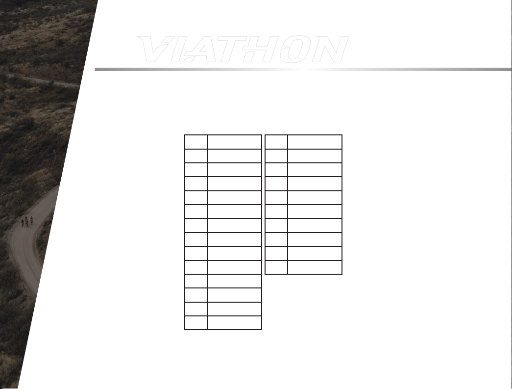
FRAME DIAGRAM .......................................................... 6
ASSEMBLY SYMBOLS................................................... 8
SEAT POST INSTALLATION .......................................... 10
WHEEL INSTALLATION ................................................. 12
STEM ALIGNMENT ........................................................ 16
HANDLEBAR INSTALLATION ....................................... 18
DRIVE SIDE PEDAL INSTALLATION ............................ 20
NON-DRIVE SIDE PEDAL INSTALLATION .................. 22
BRAKE ADJUSTMENT .................................................. 24
SADDLE ADJUSTMENT ................................................ 26
TIRE INFLATION ............................................................. 30
4
Page 5

VIATHONBICYCLES.COM
5
Page 6
FRAME DIAGRAM
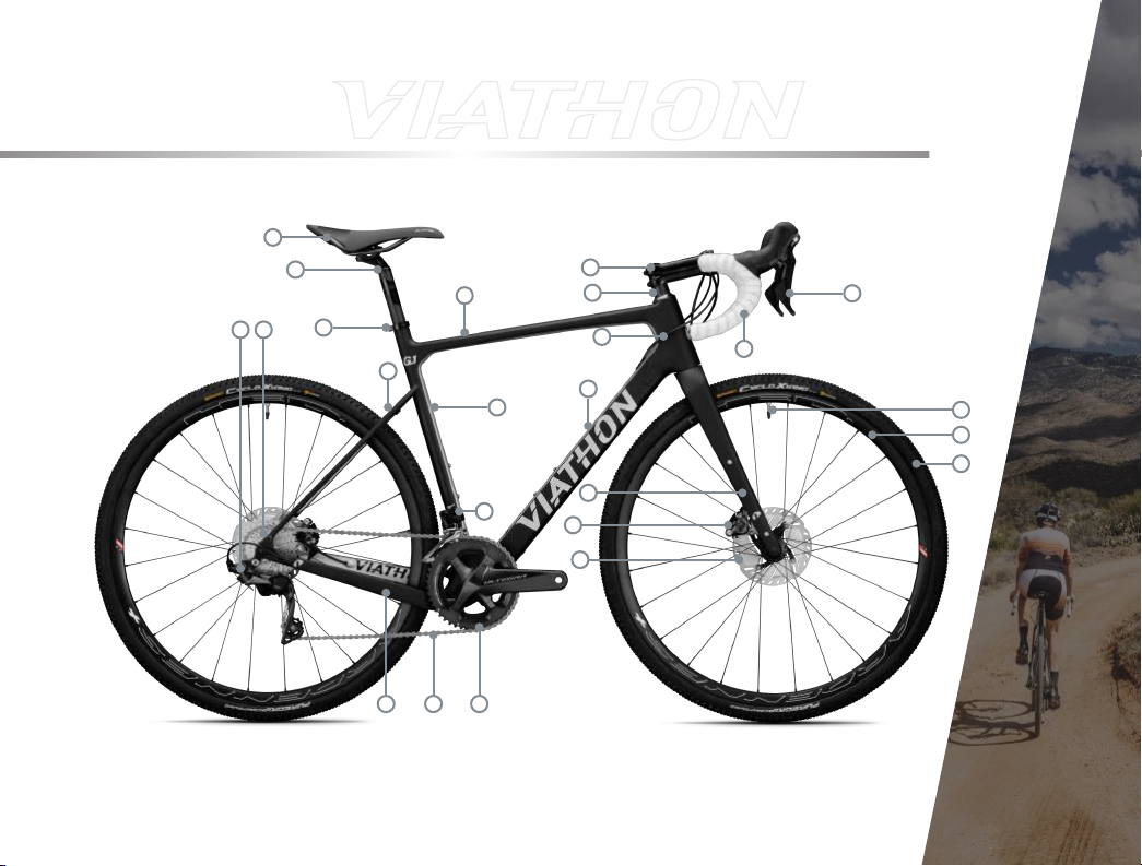
Please carefully inspect the image. It gives you a thorough break down of the
names of the tubes that the frame/ fork consist of and the components that this
bike uses. Please refer back to this image as needed.
1 Top Tube
2 Fork
3 Head Tube
4 Dow n Tube
5 Chain Stay
6 Seat Stay
7 Sea t Tube
8 Seat Post
9 Saddle
10 Seat Post C lamp
11 HeadSet Spacer
12 Stem
13 Handle Bar
14 Brake Lever
15 Rear Derailleur
16 Cassette
17 Chain
18 Crank
19 Front Derailleur
20 Brake Caliper
21 Brake Rotor
22 Tire
23 Tire Valv e
24 Rim
6
Page 7
FRAME DIAGRAM
9
8
1
10
1615
6
7
19
17
5
18
12
11
3
4
2
20
21
13
14
23
24
22
7
Page 8
ASSEMBLY SYMBOLS
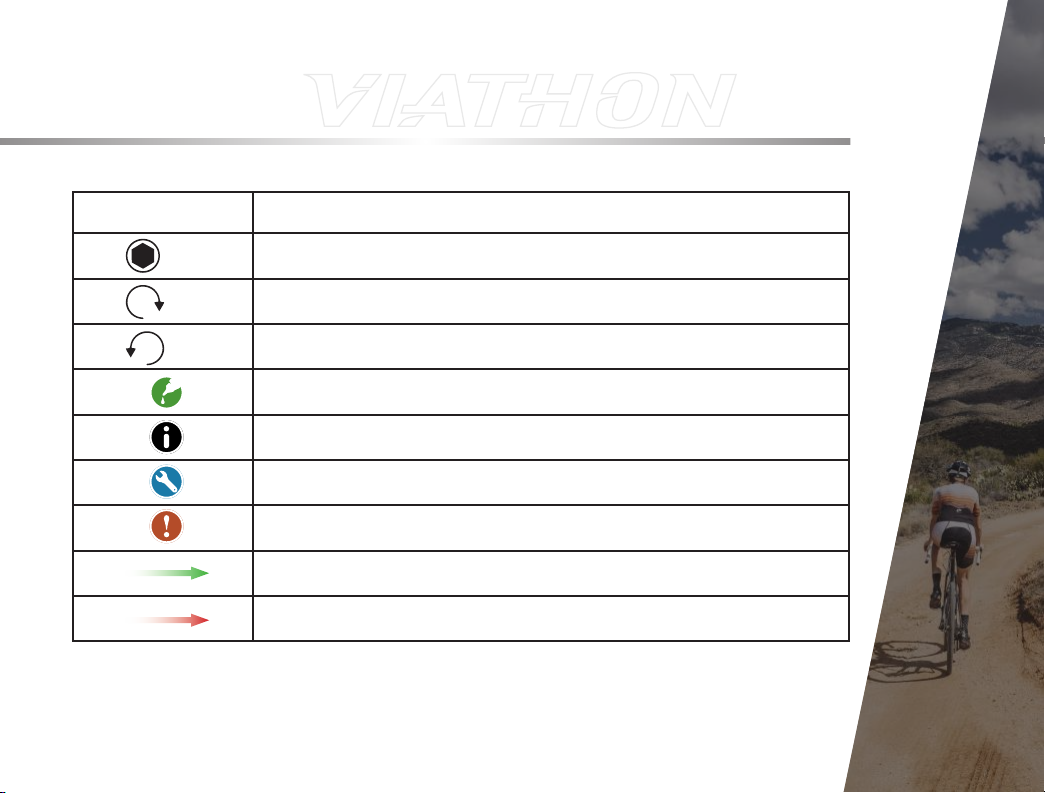
Please inspect the following chart. It depicts the symbols that will be used in this
manual and what they mean. Please refer back to this page as needed.
The following section will explain how to assemble the bike. These instructions
use text and images to explain how to safely and accurately assemble the bike.
Please follow these instructions carefully and deliberately. This bike can also be
taken to any Viathon dealer or local bike shop to get assembled.
8
Page 9
ASSEMBLY SYMBOLS
SYMBOL EXPLANATION
M8
8Nm
8Nm
Necessary Hex tool
clockwise rotatioN aNd tigHteNiNg torque of screw
couNter clockwise rotatioN aNd tigHteNiNg torque of screw
grease iNdicated surfaces
Note
assembly Note
cautioN
first iN sequeNce of work steps
Next iN sequeNce of work steps
9
Page 10

SEAT POST INSTALLATION
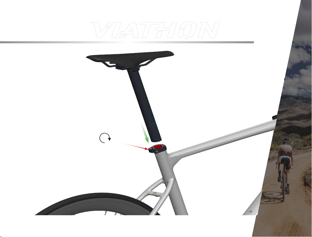
Before assembling the seat post ,apply carbon fiber assembly gel (such as fiber
grip) to the inside surface of the seat tube. Next, insert the seat tube and tighten
the seat post clamp to 5 Nm.
10
Make sure the minimum insertion mark is completely inside the Seat tube.
Page 11
SEAT POST INSTALLATION
5Nm
11
Page 12
WHEEL INSTALLATION
Place the wheel in the fork drop outs. Align the brake rotor between the pads in
the brake caliper as a guide to place the wheel fully in the dropouts.
12
Page 13

WHEEL INSTALLATION
13
Page 14
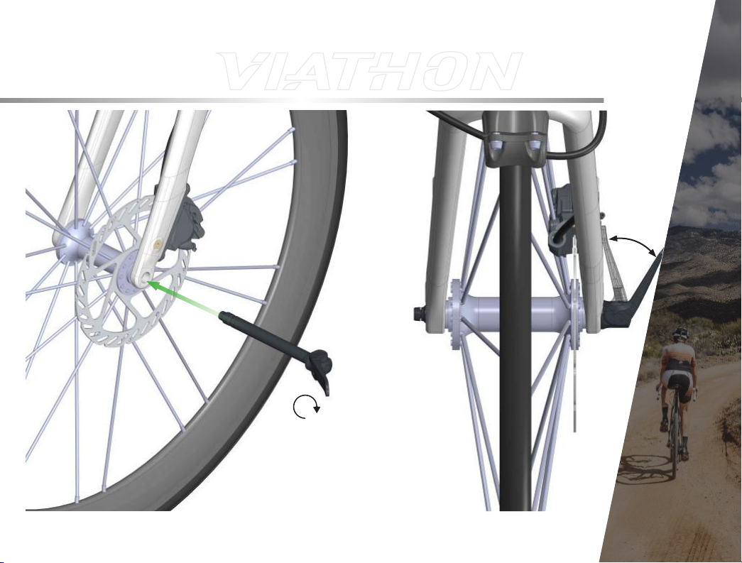
WHEEL INSTALLATION
Insert the thru axle through the dropouts from the non-drive side. The skewer goes
through the hub then threads into the drive-side dropout. Rotate the skewer and
test flipping the lever from the open to closed position periodically. When you start
to feel some resistance in the half-way position, move to the full-closed position.
If the lever is in a bad position to open and close do not adjust the closing force.
Take the bike to a Viathon dealer or local bike shop
14
Page 15
WHEEL INSTALLATION
15
Page 16
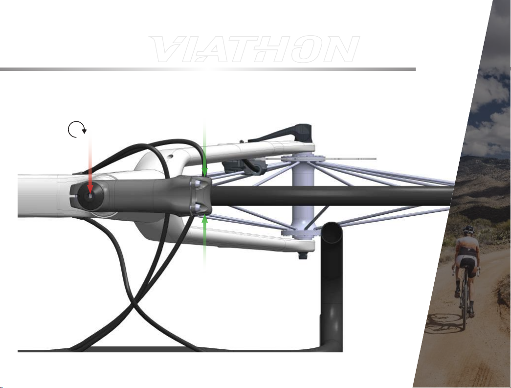
STEM ALIGNMENT17STEM ALIGNMENT
Make sure the stem is aligned so it’s centered above the front wheel. If it needs
to be adjusted, loosen the stem cap bolt and the 2 bolts that clamp the stem to
the fork. The bolts don’t have to be removed, just loosened off enough to rotate
the stem independently from the fork. Align the stem over the center of the front
wheel so they are facing the same direction. Tighten the bolt until there is no play
in the fork. Over tightening will make the steering stiff and unresponsive. Under
tightening the bolt will result in play in the fork. (5.5 Nm Thomson stem U.G.)
Note: To check if it’s too loose you can lift the front end and drop it from
about one foot high, if you hear or feel rattling it is too loose. You can also
hold the front brake and rock the handlebars forward and backwards, if the
stem cap bolt is too loose you will feel rocking. Turn the stem side to side to
check if it is too tight.
16
Page 17
5.5Nm
Page 18

HANDLEBAR INSTALLATION
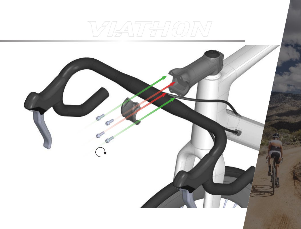
Start by removing the faceplate. Set the faceplate and bolts down somewhere
accessible. Untangle the cables if necessary. Use carbon assembly gel on the
clamping area of the stem and face plate. Center the handlebars in the stem. Hold
the handlebar in place. Install the faceplate to clamp the handlebars in place.
Tighten bolts gradually in a cross pattern and tighten them to 5Nm. Make sure the
upper grip portion of the brake levers and the bottom portion of the drop bars are
parallel to the ground i.e. horizontal
18
Page 19
HANDLEBAR INSTALLATION
5Nm
19
Page 20
DRIVE SIDE PEDAL INSTALLATION
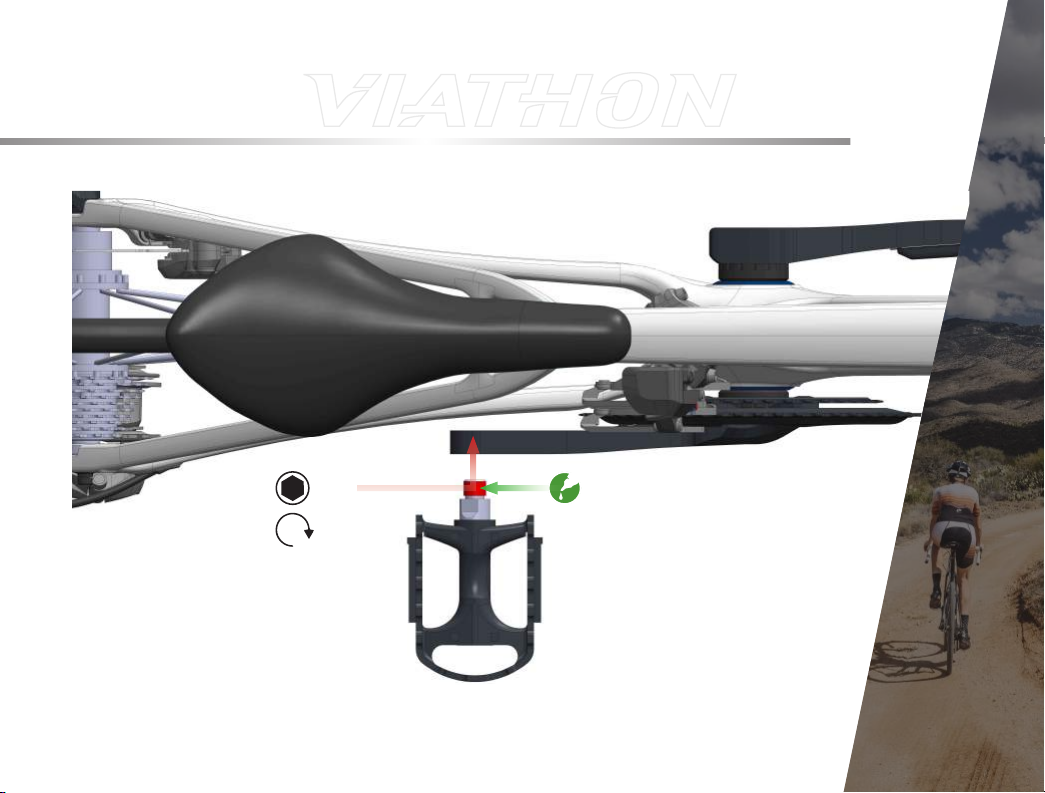
The drive side pedal (marked R) installs on the crank, on the side that has the
chainring(s). Apply a thin layer of grease to the threads. Start threading the pedal
in by hand, turning it clockwise (towards the front of the bike when viewing facing
towards the bike from the drive side). Continue to thread the pedals in using the
8mm allen wrench. Tighten firmly, about 34Nm.
20
Page 21
DRIVE SIDE PEDAL INSTALLATION
M8
34Nm
21
Page 22

NON-DRIVE SIDE PEDAL INSTALLATION
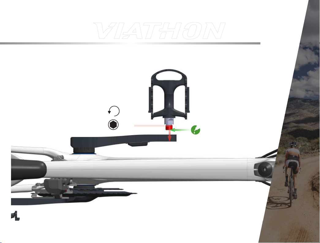
Non-drive side pedal installation.The drive side pedal (marked L) installs on
the crank on the side that does not have the chainring(s). Apply a thin layer of
grease to the threads. Start by threading the pedal in by hand, turning it counterclockwise (towards the front of the bike when viewing the bike from the non-drive
side). Continue to thread the pedals in using the 8mm allen key. Tighten firmly to
about 34Nm.
22
Page 23
NON-DRIVE SIDE PEDAL INSTALLATION
34Nm
M8
23
Page 24
BRAKE ADJUSTMENT
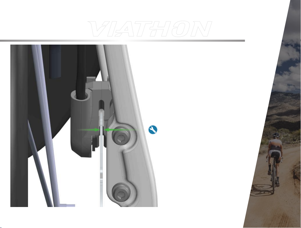
Verify that the rear brake is working properly. Lift the rear wheel off the ground
and spin it. Look inside the caliper to see/ hear if the rotor is rubbing against the
break pad. Check that the front and rear brake levers have the same amount of
travel when applying the brakes. If the rotor is rubbing, loosen the brake caliper
mounting bolts. Squeeze the brake lever and tighten the brake caliper mounting
bolts. If there is still rubbing loosen the brake caliper mounting bolts and try to
align the rotor by looking into the caliper and visually placing the rotor so there is
space between the pads and rotor. Be sure to either be hold the brake levers or
holding the caliper in place while tightening the mounting bolts.
24
Page 25
BRAKE ADJUSTMENT
25
Page 26
SADDLE ADJUSTMENT
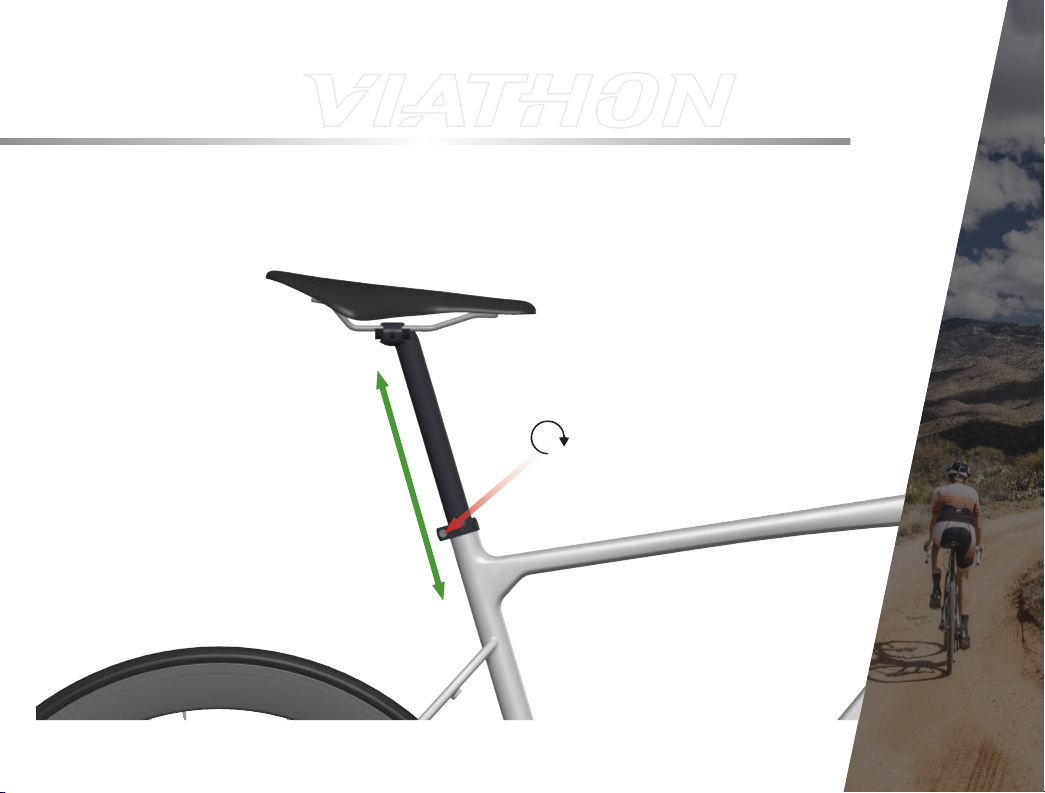
Check the saddle position. The saddle should be level i.e. parallel to the ground
and high enough to get near to a full extension of the leg when at the bottom
of the crank rotation while maintaining a slight bend at the knee to prevent
hyperextension. The saddle height can be adjusted by loosening the seatpost
clamp. Typically the appropriate height is close to your hip. When the saddle is at
the correct height tighten the seatpost clamp back to 5Nm.
26
Page 27
SADDLE ADJUSTMENT
5Nm
27
Page 28
SADDLE ADJUSTMENT
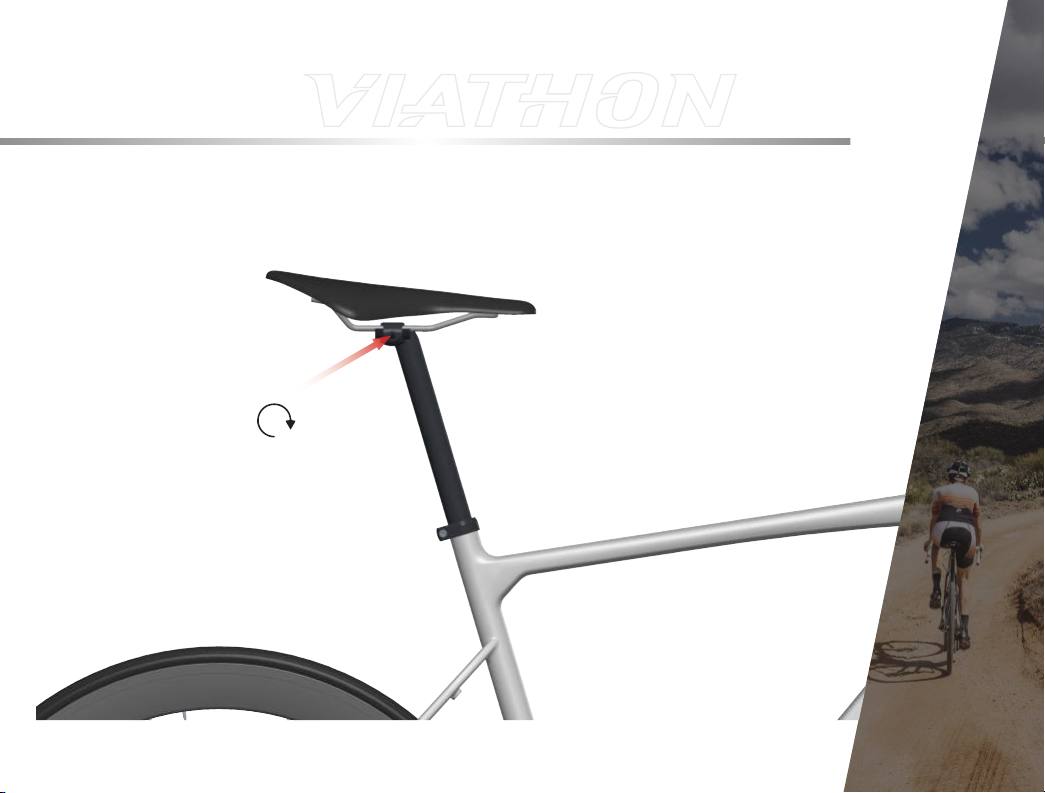
To adjust the seatpost loosen both bolts on the underside of the saddle rail clamp.
Adjust the saddle to the desired position. Gradually tighten the saddle rail clamp
bolts, alternating between them. Pay attention to how tightening the bolts effects
the saddle position. The appropriate torque for these bolts is 5Nm
28
Page 29
5Nm
SADDLE ADJUSTMENT
29
Page 30
TIRE INFLATION
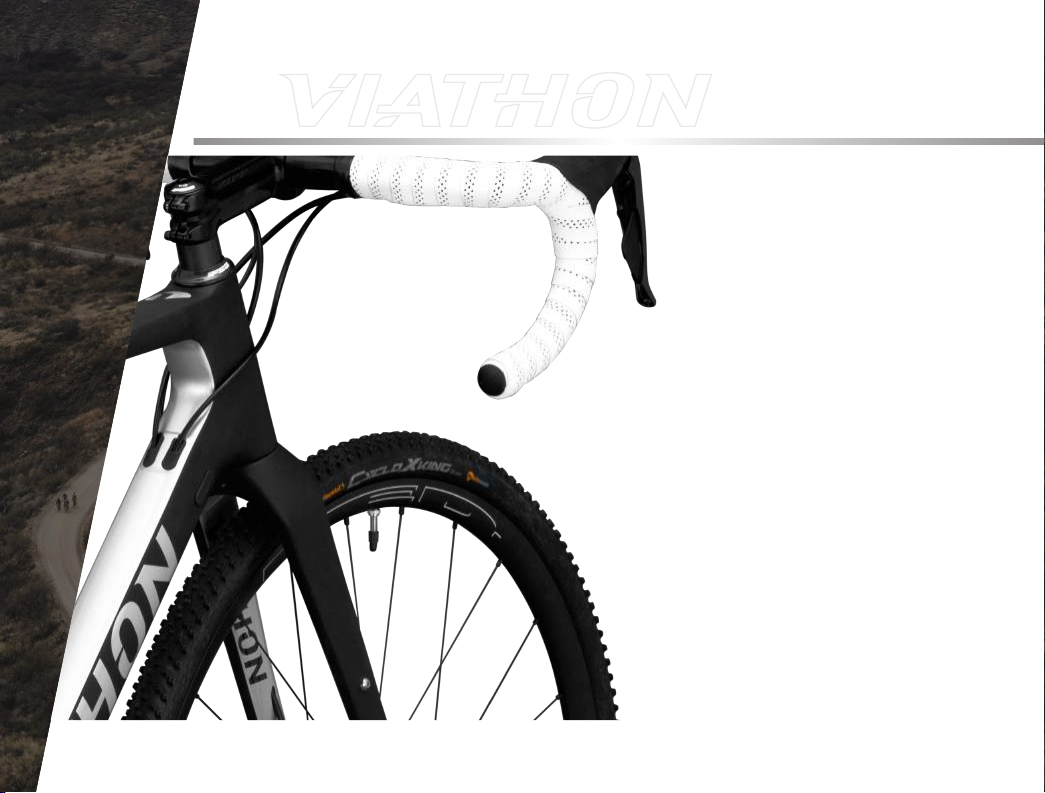
Inflate the tires. Find the marking on
the tires that indicates the appropriate
pressure range for those tires. Remove
the dust cap and open the valve. Inflate
the tire to the appropriate pressure, then
close the valve and put the dust cap back
on.
30
Page 31

ENJOY THE RIDE
31
Page 32

VIATHONBICYCLES.COM
 Loading...