

VIA Technologies VX800 Series, VX820 Series, VX820UT, VX820, VX800UT Programming Manual
...Page 1

System
Programming
Manual
.
nc
I
s
e
VX800 / VX820
i
l
og
Series
i
a
d
e
nol
nt
r
h
c
e
de
i
qui
e
T
I
A
onf
C
R
A
V
D
N
Preliminary Revision 0.95
June 20, 2008
VIA TECHNOLOGIES, INC.
Page 2

Copyright Notice:
Copyright © 2007-2008 VIA Technologies Incorporated. All Rights Reserved. No part of this document may be reproduced, transmitted,
transcribed, stored in a retrieval system or translated into any language, in any form or by any means, electronic, mechanical, magnetic, optical,
chemical, manual or otherwise without the prior written permission of VIA Technologies Incorporated. The material in this document is for
information only and is subject to change without notice. VIA Technologies Incorporated reserves the right to make changes in the product design
without reservation and without notice to its users.
Trademark Notices:
VX800 and VX820 may only be used to identify products of VIA Technologies.
Windows Vista
Microsoft Corp.
Memory Stick
Memory Stick Pro
MultiMediaCard
TM
is a trademark of Motorola Incorporated.
SPI
AGP™ is a trademark of the AGP Implementors Forum.
PCI™ is a trademark of the PCI Special Interest Group.
PS/2™ is a trademark of International Business Machines Corp.
All trademarks are the properties of their respective owners.
TM
, Windows XP™, Windows 2000™, Windows ME™, Windows 98™, VMR™ and Plug and Play™ are registered trademarks of
TM
is a registered trademark of Sony Corporation.
TM
is a trademark of Sony Corporation.
TM
is a trademark of MultiMediaCard Association.
.
Disclaimer Notice:
No license is granted, implied or otherwise, under any patent or patent rights of VIA Technologies, Inc. VIA Technologies makes no warranties,
implied or otherwise, in regard to this document and to the products described in this document. The information provided by this document is
believed to be accurate and reliable as of the publication date of this document. However, VIA Technologies assumes no responsibility for any
errors in this document. Furthermore, VIA Technologies assumes no responsibility for the use or misuse of the information in this document and for
any patent infringements that may arise from the use of this document. The information and product specifications within this document are subject
to change at any time, without notice and without obligation to notify any person of such change.
s
e
i
nc
I
l
Offices:
VIA Technologies Incorporated
USA Office:
940 Mission Court
Fremont, CA 94539
USA
Tel: (510) 683-3300
Fax: (510) 683-3301 or (510) 687-4654
Home Page:
http://www.viatech.com
VIA Technologies Incorporated
Taiwan Office:
st
Floor, No. 531
1
Chung-Cheng Road, Hsin-Tien
Taipei, Taiwan ROC
Tel: (886-2) 2218-5452
Fax: (886-2) 2218-5453
c
Home page:
e
nol
h
http://www.via.com.tw
og
de
i
i
nt
qui
e
a
d
e
r
T
V
I
A
onf
C
D
R
A
N
Page 3

VX800 / VX820 Series System Programming Manual
TABLE OF CONTENTS
TABLE OF CONTENTS....................................................................................................................................................................I
LIST OF TABLES ...........................................................................................................................................................................VI
LIST OF FIGURES .........................................................................................................................................................................VI
REGISTERS OVERVIEW ............................................................................................................................................................... 1
REGISTER DOCUMENT INTRODUCTION ........................................................................................................................................ 1
MODULE AND REGISTER SCOPE DEFINITIONS ............................................................................................................................. 2
Module Name Abbreviations................................................................................................................................................. 2
Register Scope Map Within Modules.................................................................................................................................... 2
REGISTER TABLE FORMAT ........................................................................................................................................................... 4
Column Definitions................................................................................................................................................................. 4
Attribute Definitions: ............................................................................................................................................................. 4
Special Default Value Definitions.......................................................................................................................................... 4
PCI ARBITER CONTROL ............................................................................................................................................................... 5
PCI CONFIGURATION SPACE I/O ................................................................................................................................................. 5
NORTH MODULE REGISTER DESCRIPTIONS........................................................................................................................ 6
DEVICE 0 FUNCTION 0 (D0F0): HOST CONTROLLER .................................................................................................................. 6
Header Registers (00-3Fh) ..................................................................................................................................................... 6
Multiple Function and Legacy Space Access Control (4F-C6h)......................................................................................... 9
Control Registers for Integrated Graphics / Video Processor (C7-FFh) .........................................................................10
DEVICE 0 FUNCTION 1 (D0F1): ERROR REPORTING ................................................................................................................. 12
Header Registers (00-3Fh) ................................................................................................................................................... 12
Host Bus Error Report (60-6Fh) ......................................................................................................................................... 15
DEVICE 0 FUNCTION 2 (D0F2): HOST BUS CONTROL................................................................................................................ 16
Header Registers (00-3Fh) ................................................................................................................................................... 16
Host CPU Control (50-5Fh) ................................................................................................................................................. 19
Host Interface DRDY Timing Control (60-6Fh) ................................................................................................................ 24
Host AGTL+ I/O Circuit (70–8Fh)...................................................................................................................................... 27
Miscellaneous Control (90–9Eh).......................................................................................................................................... 35
DEVICE 0 FUNCTION 3 (D0F3): DRAM BUS CONTROL ............................................................................................................ 36
Header Registers (00–3Fh)................................................................................................................................................... 36
DRAM Rank (Row) Ending / Beginning Address (40–4Fh) ............................................................................................. 39
MA Map / Command Rate (50–53h)................................................................................................................................... 41
Physical-to-Virtual Rank Mapping (54–57h) ..................................................................................................................... 42
Virtual Rank Interleave Address Select / Enable (58–5Fh) .............................................................................................. 43
DRAM Timing (60–64h)....................................................................................................................................................... 45
DRAM Queue / Arbitration (65–67h) ................................................................................................................................. 47
DRAM Control (68–69h)...................................................................................................................................................... 48
Refresh Control (6A–6Bh) ................................................................................................................................................... 48
DDR SDRAM Control (6C–6Fh)......................................................................................................................................... 49
DRAM Signal Timing Control (70–7Fh) ............................................................................................................................ 51
Read-Only Control (7C-7Fh)............................................................................................................................................... 54
Shadow RAM Control (80–83h) .......................................................................................................................................... 54
DRAM Above 4G Support (84-8Dh) ................................................................................................................................... 56
DRAM Clocking Control (90-9Fh)...................................................................................................................................... 58
UMA Registers (A0–AFh).................................................................................................................................................... 62
GMINT and AGPCINT Registers (B0–BFh) ..................................................................................................................... 64
I
V
T
A
c
e
nol
h
onf
C
N
og
de
i
A
D
s
e
i
nt
e
R
nc
I
l
a
i
qui
.
d
e
r
Preliminary Revision 0.95, June 20, 2008 -i- Table of Contents
Page 4

VX800 / VX820 Series System Programming Manual
DDR2 – I/O Pad Termination and Driving Control (D0–DFh) ........................................................................................ 66
DRAM Driving Control (E0–EBh)...................................................................................................................................... 73
DRAM CKG Control (EC–EFh)......................................................................................................................................... 75
DQ / DQS CKG Output Delay Control (F0–F9h).............................................................................................................. 76
DDR2 – DQ De-Skew Control (FA–FFh) ........................................................................................................................... 77
DEVICE 0 FUNCTION 4 (D0F4): POWER MANAGEMENT CONTROL .......................................................................................... 80
Header Registers (00-3Fh) ................................................................................................................................................... 80
Power Management Control (80–EFh)............................................................................................................................... 82
DEVICE 0 FUNCTION 5 (D0F5): APIC AND CENTRAL TRAFFIC CONTROL .............................................................................. 91
Header Registers (00–3Fh)................................................................................................................................................... 91
Legacy APIC Base I/O Registers (40–5Fh)......................................................................................................................... 93
Central Traffic - Downstream Control (60–7Fh)............................................................................................................... 95
Central Traffic - Upstream Control (80-85h)..................................................................................................................... 97
PCIe Message Controller and Power Management (A0–FFh) ......................................................................................... 99
DEVICE 0 FUNCTION 6 (D0F6): SCRATCH REGISTERS ............................................................................................................ 102
Header Registers (00-3Fh) ................................................................................................................................................. 102
Scratch Registers (40-7F)................................................................................................................................................... 104
Hash Data Control Registers (C0–FFh)............................................................................................................................ 105
DEVICE 0 FUNCTION 7 (D0F7): NORTH-SOUTH MODULE INTERFACE CONTROL.................................................................. 108
Header Registers (00-3Fh) ................................................................................................................................................. 108
North-South Module Interface Control (40–60h) ............................................................................................................ 111
Shadow RAM Control (61-6Fh) ........................................................................................................................................ 111
Host-PCI Bridge Control (70-FFh) ................................................................................................................................... 113
DEVICE 2 FUNCTION 0 (D2F0) – PCI EXPRESS ROOT PORT G0 (PCI-TO-PCI VIRTUAL BRIDGE) ...................................... 114
Header Registers (00-3Fh) ................................................................................................................................................. 115
PCI Express Capability Registers (40-67h)...................................................................................................................... 122
PCI Power Management Capability Structure Registers (68-6Fh)................................................................................ 128
PCI Message Signal Interrupt (MSI) Capability Structure Registers (70-87h) ............................................................ 129
Message Signal Interrupt (MSI) Capability Registers (88-97h) ..................................................................................... 130
Subsystem ID and Subsystem Vendor ID Capability Registers (98-9Fh)...................................................................... 130
PCI Express Transaction Layer Registers (A0-AFh) ...................................................................................................... 131
PCI Express Data Link Layer Registers (B0-BFh).......................................................................................................... 135
PCI Express Physical Layer Registers (C0-CFh)............................................................................................................. 140
PCI Express Power Management Module Registers (D0-D3h) ...................................................................................... 144
PCI Express Message Controller Related Registers (D8-DFh)....................................................................................... 145
PCI Express Electrical PHY Registers (E0-EFh)............................................................................................................. 145
PCI Express Electrical PHY Test Registers (F0-FFh)..................................................................................................... 147
DEVICE 2 FUNCTION 0 (D2F0) – PCI EXPRESS ROOT PORT G0 EXTENDED SPACE .............................................................. 149
Advanced Error Reporting Capability (100-13Fh).......................................................................................................... 149
Virtual Channel Capability (140-14Fh) ............................................................................................................................ 152
VC0 Resource (150-15Bh).................................................................................................................................................. 153
VC1 Resource (15C-19Fh) ................................................................................................................................................. 154
DEVICE 3 FUNCTION 0 (D3F0) – PCI EXPRESS ROOT PORT 0 (PCI-TO-PCI VIRTUAL BRIDGE).......................................... 155
Header Registers (00-3Fh) ................................................................................................................................................. 155
PCI Express Capability Registers (40-67h)...................................................................................................................... 162
PCI Power Management Capability Structure Registers (68-6Fh)................................................................................ 168
PCI Message Signal Interrupt (MSI) Capability Structure Registers (70-87h) ............................................................ 169
Message Signal Interrupt (MSI) Capability Registers (88-97h) ..................................................................................... 170
Subsystem ID and Subsystem Vendor ID Capability Registers (98-9Fh)...................................................................... 170
PCI Express Transaction Layer Registers (A0-AFh) ...................................................................................................... 171
PCI Express Data Link Layer Registers (B0-BFh).......................................................................................................... 175
PCI Express Physical Layer Registers (C0-CFh)............................................................................................................. 180
PCI Express Power Management Module Registers (D0-D3h) ...................................................................................... 184
PCI Express Message Controller Related Registers (D8-DFh)....................................................................................... 185
I
V
T
A
c
e
nol
h
onf
C
N
og
de
i
A
D
s
e
i
nt
e
R
nc
I
l
a
i
qui
.
d
e
r
Preliminary Revision 0.95, June 20, 2008 -ii- Table of Contents
Page 5

VX800 / VX820 Series System Programming Manual
PCI Express Electrical PHY Registers (E0-EFh)............................................................................................................. 185
PCI Express Electrical PHY Test Registers (F0-FFh)..................................................................................................... 186
DEVICE 3 FUNCTION 0 (D3F0) – PCI EXPRESS ROOT PORT 0 EXTENDED SPACE ................................................................. 188
Advanced Error Reporting Capability (100-13Fh).......................................................................................................... 188
Virtual Channel Capability (140-14Fh) ............................................................................................................................ 191
VC0 Resource (150-15Bh).................................................................................................................................................. 192
VC1 Resource (15C-19Fh) ................................................................................................................................................. 193
DEVICE 3 FUNCTION 1 (D3F1) – PCI EXPRESS ROOT PORT 1 (PCI-TO-PCI VIRTUAL BRIDGE).......................................... 194
Header Registers (00-3Fh) ................................................................................................................................................. 194
PCI Express Capability Registers (40-67h)...................................................................................................................... 201
PCI Power Management Capability Structure Registers (68-6Fh)................................................................................ 207
PCI Message Signal Interrupt (MSI) Capability Structure Registers (70-87h) ............................................................ 208
Message Signal Interrupt (MSI) Capability Registers (88-97h) ..................................................................................... 209
Subsystem ID and Subsystem Vendor ID Capability Registers (98-9Fh)...................................................................... 209
PCI Express Transaction Layer Registers (A0-AFh) ...................................................................................................... 210
PCI Express Data Link Layer Registers (B0-BFh).......................................................................................................... 214
PCI Express Physical Layer Registers (C0-CFh)............................................................................................................. 218
PCI Express Power Management Module Registers (D0-D3h) ...................................................................................... 222
PCI Express Message Controller Related Registers (D8-DFh)....................................................................................... 223
PCI Express Electrical PHY Registers (E0-EFh)............................................................................................................. 224
PCI Express Electrical PHY Test Registers (F0-FFh)..................................................................................................... 225
DEVICE 3 FUNCTION 1 (D3F1) – PCI EXPRESS ROOT PORT 1 EXTENDED SPACE.................................................................. 227
Advanced Error Reporting Capability (100-13Fh).......................................................................................................... 227
Virtual Channel Capability (140-14Fh) ............................................................................................................................ 230
VC0 Resource (150-15Bh).................................................................................................................................................. 231
VC1 Resource (15C-19Fh) ................................................................................................................................................. 232
PCI EXPRESS ROOT COMPLEX REGISTER BLOCK – HOST ..................................................................................................... 233
Virtual Channel Capability (000-00Fh) ............................................................................................................................ 233
VC0 Resource (010-01Bh).................................................................................................................................................. 234
Root Complex Link Declaration Enhanced Capability (040-04Fh) ............................................................................... 235
Link Entry for PEG0 (050-05Fh) ...................................................................................................................................... 235
Link Entry for PE0 (060-06Fh) ......................................................................................................................................... 236
Link Entry for PE1 (070-07Fh) ......................................................................................................................................... 236
Link Entry for HDAC (080-08Fh)..................................................................................................................................... 237
VC Arbitration Timer (200-20Fh)..................................................................................................................................... 238
Port Arbitration Timer for VC0 (210-219h) .................................................................................................................... 238
Host Side Upstream Arbitration Timers (230-23Fh)....................................................................................................... 240
PXPTRF (Central Traffic Controller) P2P Arbitration Timer of PCIe (250-253h)..................................................... 242
I
T
A
c
e
nol
h
onf
C
V
SOUTH MODULE REGISTER DESCRIPTIONS .................................................................................................................... 243
LEGACY I/O PORTS ................................................................................................................................................................... 243
Keyboard Controller I/O Registers................................................................................................................................... 245
DMA Controller I/O Registers .......................................................................................................................................... 249
DMA Controller Shadow Registers................................................................................................................................... 250
Interrupt Controller I/O Registers.................................................................................................................................... 251
Interrupt Controller I/O Shadow Registers ..................................................................................................................... 251
Timer / Counter I/O Registers........................................................................................................................................... 252
Timer / Counter Shadow Registers ................................................................................................................................... 252
CMOS / RTC I/O Registers ............................................................................................................................................... 252
Keyboard / Mouse Wakeup Index / Data Registers......................................................................................................... 255
Keyboard / Mouse Wakeup Registers............................................................................................................................... 256
MEMORY MAPPED I/O APIC REGISTERS................................................................................................................................258
Indexed I/O APIC Registers .............................................................................................................................................. 259
INDEXED I/O UART DMA CONTROL REGISTERS .................................................................................................................. 262
N
og
de
i
A
D
s
e
i
nt
e
R
nc
I
l
a
i
qui
.
d
e
r
Preliminary Revision 0.95, June 20, 2008 -iii- Table of Contents
Page 6

VX800 / VX820 Series System Programming Manual
DEVICE 12 FUNCTION 0 (D12F0) - SDIO HOST CONTROLLER............................................................................................... 264
PCI Configuration Space Header (00-3Fh)...................................................................................................................... 264
PCI Device Specific Registers (40-FFh)............................................................................................................................ 266
SDIO HOST STANDARD REGISTERS (00-FFH) ......................................................................................................................... 271
IRDA HOST CONTROLLER I/O SPACE REGISTERS.................................................................................................................. 280
DEVICE 13 FUNCTION 0 (D13F0) – SECURE DIGITAL MEMORY CARD CONTROLLER........................................................... 291
PCI Configuration Space Header (00-3Fh)...................................................................................................................... 291
PCI Card Reader - Specific Configuration Registers (40-FFh)...................................................................................... 295
SDC MMIO Registers (00-FFh) ........................................................................................................................................ 297
Data DMA Control Registers (00-FFh)............................................................................................................................. 305
CICH DMA Control Registers (00-FFh) .......................................................................................................................... 307
PCI Control Registers (00-FFh) ........................................................................................................................................310
DEVICE 15 FUNCTION 0 (D15F0): SERIAL ATA & EIDE CONTROLLER ............................................................................... 312
Header Registers (00-3Fh) ................................................................................................................................................. 312
SATA Registers (40-47h).................................................................................................................................................... 318
EIDE Registers (48-54h)..................................................................................................................................................... 320
SATA Link Control Registers (55-56h) ............................................................................................................................ 322
SATA PHY Control Registers (57-5Eh) ........................................................................................................................... 323
SATA Hot Plug and RAMBIST Status Registers (5F-63h)............................................................................................. 325
SATA Analog PHY Control (64-77h)................................................................................................................................ 326
Miscellaneous Registers (78-7Fh)...................................................................................................................................... 331
SATA Transport Control Registers (80-8Fh)................................................................................................................... 332
SATA SCR Registers (A0-AFh)......................................................................................................................................... 334
Legacy / Back Door Registers (B0-BFh) ........................................................................................................................... 336
EIDE Registers (C0-FFh)................................................................................................................................................... 338
DEVICE 16 FUNCTION 0-2 (D16F0-F2) – USB 1.1 UHCI PORTS 0-5...................................................................................... 342
PCI Configuration Space Header (00-3Fh)...................................................................................................................... 342
USB 1.1-Specific Configuration Registers (40-FFh) ........................................................................................................ 345
USB 1.1 I/O Registers (00-13h).......................................................................................................................................... 349
DEVICE 16 FUNCTION 4 REGISTERS - USB 2.0 EHCI ............................................................................................................. 350
PCI Configuration Space Header (00-3Fh)...................................................................................................................... 350
USB 2.0-Specific Configuration Registers (40-FCh)........................................................................................................ 353
EHCI USB 2.0 I/O Registers (00-B3h).............................................................................................................................. 360
DEVICE 17 FUNCTION 0 (D17F0) - BUS CONTROL AND POWER MANAGEMENT .................................................................... 364
PCI Configuration Space Header (00-3Fh)...................................................................................................................... 364
ISA Bus Control (40-49h)................................................................................................................................................... 366
LPC Firmware Memory Control (4A-4Bh)...................................................................................................................... 370
Miscellaneous Control (4C-4Fh)........................................................................................................................................ 370
Function Control (50-51h) ................................................................................................................................................. 372
Serial IRQ, LPC and PC / PCI DMA Control (52-53h) .................................................................................................. 373
Plug and Play Control – PCI (54-57h) .............................................................................................................................. 374
GPIO and Miscellaneous Control (58-5Bh)...................................................................................................................... 376
Programmable Chip Select (PCS) Control (5C-66h)....................................................................................................... 378
Output Control (67h).......................................................................................................................................................... 379
High Precision Event Timers (HPET) (68-6Bh)............................................................................................................... 380
ISA Decoding Control (6C-6Fh)........................................................................................................................................ 381
PCI I/O Cycle Control (74-7Fh) ........................................................................................................................................ 383
Power Management-Specific Configuration Registers (80-CFh) ................................................................................... 386
UART / FIR Misc Control Registers (B0-BFh)................................................................................................................ 398
System Management Bus-Specific Configuration Registers (D0-E7h) .......................................................................... 401
Watchdog Timer Registers (E8-FFh)................................................................................................................................ 408
ACPI IO Space Registers (PMIO 00-0Bh)........................................................................................................................ 409
Processor Power Management Registers (PMIO 10-16h)............................................................................................... 412
General Purpose Power Management Registers (PMIO 20-52h)................................................................................... 413
I
V
T
A
c
e
nol
h
onf
C
N
og
de
i
A
D
s
e
i
nt
e
R
nc
I
l
a
i
qui
.
d
e
r
Preliminary Revision 0.95, June 20, 2008 -iv- Table of Contents
Page 7

VX800 / VX820 Series System Programming Manual
IO Trap Registers (PMIO 54-69h) .................................................................................................................................... 425
Watchdog Timer Memory Base (PM-MMIO 00-07h)..................................................................................................... 430
System Management Bus I/O Space Registers (SMIO 00-0Fh)...................................................................................... 431
SPI CONTROLLER ..................................................................................................................................................................... 437
DEVICE 17 FUNCTION 7 (D17F7): SOUTH-NORTH MODULE INTERFACE CONTROL .............................................................. 443
PCI Configuration Space Header (00-3Fh)...................................................................................................................... 443
South -North Module Interface Control (40-5F).............................................................................................................. 445
DRAM Configuration (60h)............................................................................................................................................... 448
Shadow RAM Control (61-64h)......................................................................................................................................... 449
Conventional PCI Bus Control (70-7Fh) .......................................................................................................................... 450
HDAC Control (D0-DFh)................................................................................................................................................... 454
Dynamic Clock Control (E0-E3h) ..................................................................................................................................... 454
DRAM Above 4G Support (E4-FFh) ................................................................................................................................ 456
DEVICE 19 FUNCTION 0 (D19F0): PCI TO PCI BRIDGE.......................................................................................................... 457
PCI Configuration Space Header (00-3Fh)...................................................................................................................... 457
DEVICE 20 FUNCTION 0 (D20F0) - HIGH DEFINITION AUDIO CONTROLLER (HDAC).......................................................... 463
PCI Configuration Space Header (00-3Fh)...................................................................................................................... 463
HDAC PCI EXTENDED CONFIGURATION SPACE (40-260H) ................................................................................................... 466
HIGH DEFINITION AUDIO CONTROLLER MEMORY MAPPED I/O REGISTERS (HDAC-MMIO) ........................................... 473
Global Capabilities and Control (00-1Bh)........................................................................................................................ 473
Interrupt Control (20-27h)................................................................................................................................................. 475
Synchronization Control (30-3Bh) .................................................................................................................................... 475
HDAC CORB (Command Output Ring Buffer) Control (40-4Eh)................................................................................ 476
HDAC RIRB (Response Input Ring Buffer) Control (50-5Eh) ...................................................................................... 477
HDAC Immediate Command Control (60-69h)............................................................................................................... 479
DMA Position Base Address (70-77h)............................................................................................................................... 480
HDAC Stream Descriptors (80-17Fh)............................................................................................................................... 481
Alias Registers (2030-2167h).............................................................................................................................................. 486
c
nol
h
og
de
i
e
s
e
i
nt
e
nc
I
l
a
i
qui
.
d
e
r
T
I
A
onf
C
R
A
V
D
N
Preliminary Revision 0.95, June 20, 2008 -v- Table of Contents
Page 8

VX800 / VX820 Series System Programming Manual
LIST OF TABLES
TABLE 1. VX800 / VX820 SERIES FEATURE COMPARISON TABLE.................................................................................. 1
TABLE 2. DYNAMIC DEFER SNOOP STALL TABLE........................................................................................................... 19
TABLE 3. CPU WRITE REQUEST POLICY............................................................................................................................. 22
TABLE 4. HOST / DRAM BANDWIDTH POLICY................................................................................................................... 23
TABLE 5. PROGRAMMING SETTING FOR DRAM CHANNELS ....................................................................................... 36
TABLE 6. RANK MA MAP TYPE TABLE................................................................................................................................. 41
TABLE 7. DRAM BANK ADDRESS TABLE ............................................................................................................................. 42
TABLE 8. RANK INTERLEAVE ADDRESS TABLE ............................................................................................................... 42
TABLE 9. CPU-TO-SMRAM CYCLE FLOW ............................................................................................................................ 55
TABLE 10. MD PADS ODT CONTROL IN DIFFERENT DRAM MODE .............................................................................67
TABLE 11. PAD ODT CONTROL GROUP SETTING ............................................................................................................. 67
TABLE 12. PHYSICAL PIN TO DRIVING GROUP MAPPING TABLE............................................................................... 73
TABLE 13. SCMD AND MA PINS POWER SAVING MODE SETTING............................................................................... 79
TABLE 14. CHIP SELECT PINS POWER SAVING MODE USAGE..................................................................................... 79
TABLE 15. PCIE PORT SUPPORT........................................................................................................................................... 114
TABLE 16. MAPPING TABLE FOR D2F0 RXC3 ................................................................................................................... 142
TABLE 17. MAPPING TABLE FOR D3F0 RXC3 ................................................................................................................... 182
TABLE 18. MAPPING TABLE FOR D3F1 RXC3 ................................................................................................................... 220
TABLE 19. KEYBOARD CONTROLLER COMMAND CODES .......................................................................................... 247
TABLE 20. CMOS REGISTER SUMMARY ............................................................................................................................ 253
TABLE 21. I/O REDIRECTION TABLE .................................................................................................................................. 260
TABLE 22. DETERMINATION OF TRANSFER TYPE.......................................................................................................... 272
TABLE 23. PROGRAMMING VALUES FOR I/O REGISTERS AT OFFSET 16-19H....................................................... 282
TABLE 24. COMMAND TYPE FIELD ENCODINGS ............................................................................................................. 298
TABLE 25. IDE/SATA SUPPORT OPTION .............................................................................................................................. 312
TABLE 26. PNP IRQ ROUTING TABLE ................................................................................................................................. 375
TABLE 27. INTERNAL APIC, PCI DEVICES IRQ ROUTING TABLE............................................................................... 375
TABLE 28. HPET IRQ ROUTING TABLE .............................................................................................................................. 375
TABLE 29. C3 LATENCY CONFIGURATION TABLE......................................................................................................... 404
TABLE 30. C4 LATENCY CONFIGURATION TABLE......................................................................................................... 405
T
c
e
A
I
nol
h
onf
C
LIST OF FIGURES
og
de
i
A
s
e
i
nt
e
R
nc
I
l
a
i
qui
.
d
e
r
FIGURE 1. DIMM / CHANNEL MAPPING DIAGRAM ..........................................................................................................44
FIGURE 2. LOOP BACK MODE SELECTIONS...................................................................................................................... 140
FIGURE 3. LOOP BACK MODE SELECTIONS...................................................................................................................... 180
FIGURE 4. LOOP BACK MODE SELECTIONS...................................................................................................................... 218
Preliminary Revision 0.95, June 20, 2008 -vi- Table of Contents
V
D
N
Page 9

VX800 / VX820 Series System Programming Manual
REGISTERS OVERVIEW
Register Document Introduction
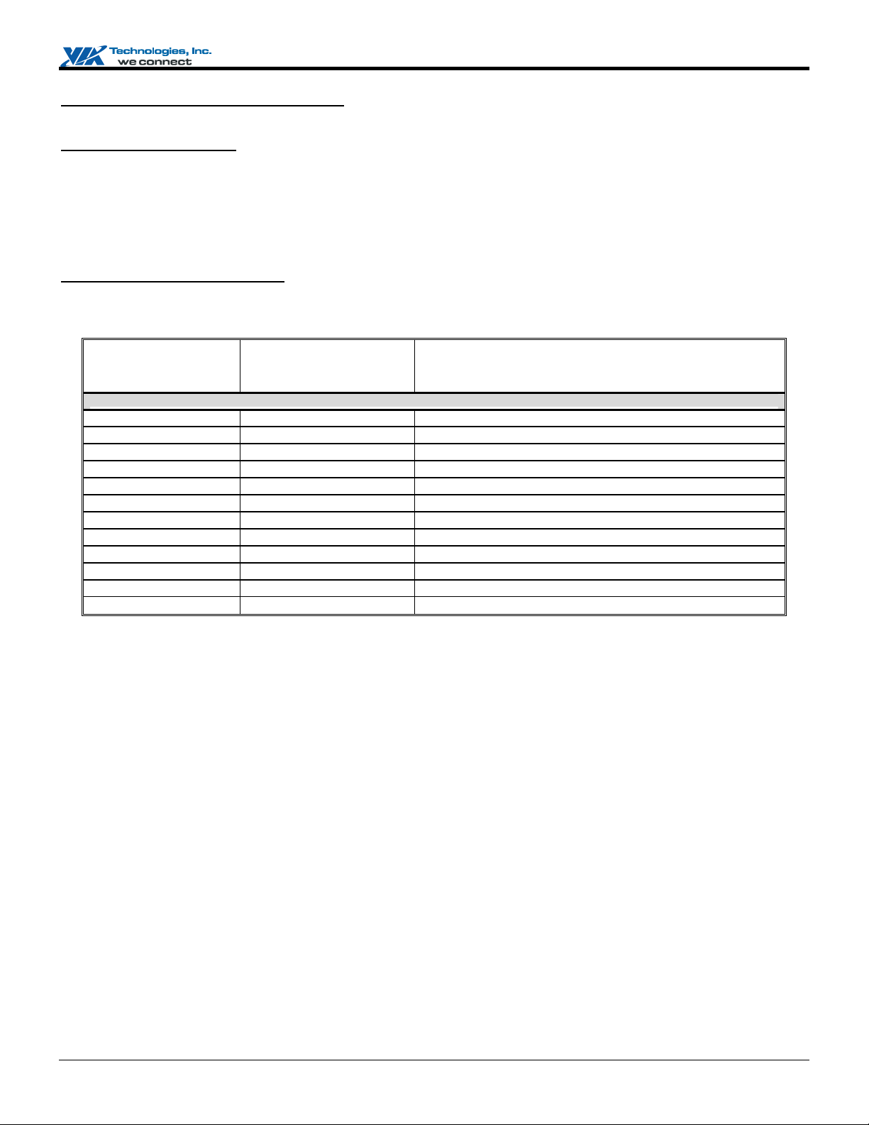
This document includes the registers for VIA VX800 and VX820 Series. Please refer to Table 1 for the specification differences
of these products.
This chip integrates functional modules of the traditional North Bridge and South Bridge chips, plus 3D/2D and Video Processors,
Video Decoding Accelerator and controller for external display interface. The register set is partitioned into three blocks: North
Module, South Module and Graphics and Video Module; of which, North Module and South Module registers are described in this
System Programming Manual while graphics and video registers are described in the Graphics and Video Programming
Guide.
Table 1. VX800 / VX820 Series Feature Comparison Table
Product Model VX800UT VX800 VX820UT VX820
FSB Speed (MHz) 400-533 400-800 533 400-800
Integrated GFX Clock (MHz) 200 250 200 250
Memory Type
PCI Express Ports
PCI
SATA
Core Voltage
Package Dimension
Note 1. Registers related to features that the product does not support should be reserved.
DDR2 533 DDR2 667 DDR2 533 DDR2 667
3x1 1x4 + 2x1 2x1 2x1
Yes Yes No No
Yes (SATA 1.0) Yes (SATA 2.0) No No
1.25V 1.5V 1.25V 1.5V
ogi
33 x 33mm FCBGA
1236 balls
hnol
c
de
i
e
o
nf
R
A
I
A
T
C
s
e
i
nt
qu
e
I
a
.
nc
l
r
i
d
21 x 21mm FCBGA
e
1086 balls
V
D
N
Preliminary Revision 0.95, June 20, 2008 -1- Registers Overview
Page 10
VX800 / VX820 Series System Programming Manual
,
g
,
,
,
,
,
,
N
,
,
,
y Sp
t
Module and Register Scope Definitions
Module Name Abbreviations
NM: North Module. It contains functional modules of the traditional North Bridge chip.
SM: South Module. It contains functional modules of the traditional South Bridge chip.
NSMIC: North-South Module Interface Control
SNMIC: South-North Module Interface Control
PM: Power Management
HDAC: High Definition Audio Controller
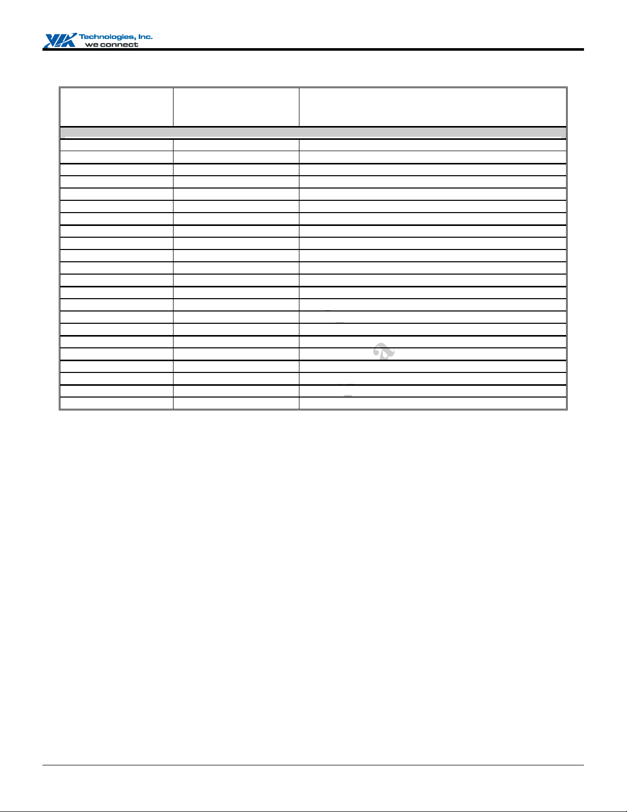
Register Scope Map Within Modules
To specifically identify every function, the following abbreviations will be applied in subsequent sections.
Abbreviation of
Register Space /
Module Name
.
Register Space Function
nc
I
s
D0F1
D0F2
D0F3
D0F4
D0F5
D0F6
D0F7
D2F0 / PEG0
D3F0 / PE0
D3F1 / PE1
RCRB-H
PCI Device 0
PCI Device 0
PCI Device 0
PCI Device 0
PCI Device 0
PCI Device 0
PCI Device 0
PCI Device 2
PCI Device 3
PCI Device 3
Memor
T
A
I
Function 1 Error Reportin
Function 2 Host Bus Control
Function 3 DRAM Bus Control
Function 4 Power Management and Chip Testing Control
Function 5 APIC and Central Traffic Control
Function 6 Scratch Registers
Function 7
Function 0 PCI Express Root Port G0 –x4, x2, x1
Function 0 PCI Express Root Port 0 –x1
hnol
Function 1 PCI Express Root Port 1 –x1
c
ace PCI Express Root Complex Register Block for Hos
ogi
orth-South Module Interface Control <NSMIC>
de
i
e
e
i
nt
qu
e
l
a
d
e
r
i
nf
o
R
C
A
V
D
N
Preliminary Revision 0.95, June 20, 2008 -2- Registers Overview
Page 11
y Sp
y Sp
y Sp
y Sp
,
,
,
,
r
p
y Sp
y Sp
,
y Sp
p
Abbreviation of
Register Space /
Module Name
VX800 / VX820 Series System Programming Manual
Register Space Function
SDIO-MMIO
SDC-MMIO
Data DMA-MMIO
CICH DMA-MMIO
PCI Control-MMIO
D16F0
D16F1
D16F2
D16F4
PMIO
PM-MMIO
SMIO
D19F0
HDAC-MMIO
-
FIR
Memory Space
Memor
Memor
Memor
Memor
PCI Device 16
PCI Device 16
PCI Device 16
PCI Device 16
IO S
Memor
Memor
PCI Device 19
Memor
IO S
A
I
SDIO Memory Mapped I/O Space Registers
ace Security Digital Controller Memory Mapped I/O Space
ace Data DMA Memory Mapped I/O Space Registers
ace CICH DMA Memory Mapped I/O Space Registers
ace PCI Control Memory Mapped I/O Space Registers
Function 0 USB 1.1 UHCI Ports 0-1
Function 1 USB 1.1 UHCI Ports 2-3
Function 2 USB 1.1 UHCI Ports 4-5
Function 4 USB 2.0 EHCI Controlle
nc
I
.
ace ACPI I/O Registers
ace Power Management Memory Mapped I/O Space Registers
ace System Management Bus I/O Space Registers
-
Function 0 PCI-to-PCI Bridge
ace HDAC Memory Mapped I/O Space Registers
ogi
s
e
l
a
i
e
ace IrDA Host Controller / IO Space Registers
nt
r
i
hnol
de
i
qu
e
R
T
c
e
nf
o
C
A
d
<
>
V
D
N
Preliminary Revision 0.95, June 20, 2008 -3- Registers Overview
Page 12

VX800 / VX820 Series System Programming Manual
Register Table Format
Column Definitions
In the register descriptions, column “Default” indicates the power-on default value of register bit(s), while column “Attribute”
indicates access type of register bit.
Attribute Definitions
Read / Write Attributes: read / write attributes may be used together to specify combined attributes
RO: Read Only.
RZ: Read as Zero.
R1: Read as 1.
WO: Write Only. (register value can not be read by the software)
IW: Ignore Write.
MW: Must Write back what is read.
XW: Backdoor Write.
RW: Read / Write.
RW1: Write Once then Read Only after that.
RW1C: Read / Write of “1” clears bit to zero.
RsvdP: Reserved. Must do a read-modify-write to preserve the bit values.
RsvdZ: Reserved. Must write 0’s.
RSM: Bits are in resume-well.
Sticky Attributes: adding a “S” in tail to indicate a sticky register, which means that register will not be set or altered by hot reset.
Ex. RWS: Sticky-Read/Write. ROS: Sticky-Read Only. RW1CS: Sticky-Write-1-to-Clear.
Special Default Value Definitions
Dip: Means the default value is set by dip switch or strapping.
HwInit: Hardware initialized; bit default value is set by hardware to reflect related status.
:
.
nc
I
s
e
l
ogi
i
a
d
e
nt
r
i
hnol
de
i
A
qu
e
R
I
A
T
c
e
nf
o
C
V
D
N
Preliminary Revision 0.95, June 20, 2008 -4- Registers Overview
Page 13
VX800 / VX820 Series System Programming Manual
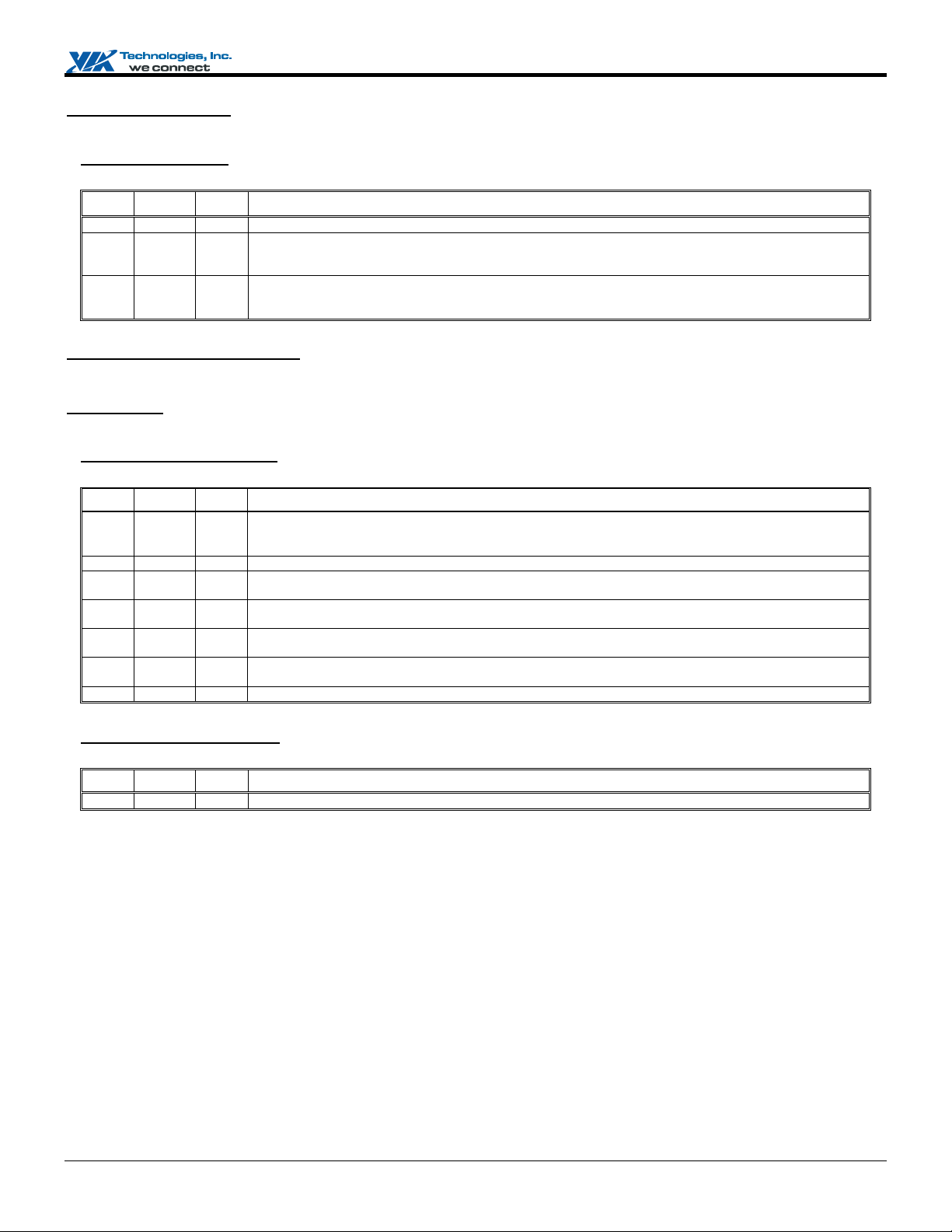
PCI Arbiter Control
I/O Port Address: 22h
PCI Arbiter Disable Default Value: 00h
Bit Attribute Default Description
7:2 RO 0
1 RW 0
0 RW 0
PCI Configuration Space I/O
This chip’s PCI space registers are addressed via the following configuration mechanism:
Mechanism #1
These ports respond only to double-word accesses. Byte or word accesses will be passed on unchanged.
I/O Port Address: CFB-CF8h
PCI Configuration Address Default Value: 0000 0000h
Reserved
PCI2 Arbiter Control
0: Enable PCI2 Bus Arbiter
1: Disable PCI2 Bus Arbiter
PCI1 Arbiter Control
0: Enable PCI1 Bus Arbiter (arbiter will respond to REQ# assertion)
1: Disable PCI1 Bus Arbiter (arbiter will not respond to PCI-1 REQ# and PREQ# assertion)
.
nc
I
s
e
Bit Attribute Default Description
31 RW 0
30:24 RO 0 Reserved (always reads 0)
23:16 RW 0
15:11 RW 0
10:8 RW 0
7:2 RW 0
1:0 RW 0 Fixed (always reads 0)
I/O Port Address: CFF-CFCh
PCI Configuration Data Default Value: 0000 0000h
Bit Attribute Default Description
31:0 RW 0
Note: Refer to PCI Bus Specification Version 2.3 for further details on operation of the above configuration registers.
V
Configuration Space Enable
0: Disable
1: Convert configuration data port writes to configuration cycles on the PCI bus
ogi
l
a
i
PCI Bus Number
Used to choose a specific PCI bus in the system
Device Number
Used to choose a specific device in the system
Function Number
Used to choose a specific function if the selected device supports multiple functions
Register Number (also called the "Offset")
Used to select a specific DWORD in the configuration space
T
A
I
PCI Configuration Data
c
e
C
hnol
de
i
nf
o
A
nt
qu
e
R
D
N
d
e
r
i
Preliminary Revision 0.95, June 20, 2008 -5- Registers Overview
Page 14
VX800 / VX820 Series System Programming Manual
NORTH MODULE REGISTER DESCRIPTIONS
Device 0 Function 0 (D0F0): Host Controller
Device 0 Function 0, the host controller, is connected to the PCI bus through AD11 as the IDSEL.
All registers are located in PCI configuration space and should be programmed using PCI configuration mechanism 1 through I/O
registers CF8 / CFC with bus number 0, device number 0 and function number 0.
Header Registers (00-3Fh)
Offset Address: 01-00h (D0F0)
Vendor ID Default Value: 1106h
Bit Attribute Default Description
15:0 RO 1106h
.
VIA Technologies ID Code
nc
Offset Address: 03-02h (D0F0)
Device ID Default Value: 0353h
Bit Attribute Default Description
15:0 RO 0353h
Offset Address: 05-04h (D0F0)
PCI Command Default Value: 0006h
Bit Attribute Default Description
15:10 RO 0
9 RO 0
8 RO 0
7 RO 0
6 RW 0
5 RO 0
4 RO 0
3 RO 0
V
2 RO 1b
1 RO 1b
0 RO 0
A
I
Device ID Code
og
Reserved
Fast Back-to-Back Cycle Enable
Hardwired to 0. (Not supported)
SERR# Enable
Hardwired to 0 (Not supported)
Address / Data Stepping
Hardwired to 0 (Not supported)
Parity Error Response
0: Ignore parity errors
T
1: Perform parity check and take normal action on detected parity errors
VGA Palette Snooping
Hardwired to 0 (Not implemented)
Memory Write and Invalidate
Hardwired to 0 (Not supported)
Respond To Special Cycle
Hardwired to 0 (Does not monitor special cycles)
PCI Master Function
Hardwired to 1 (May behave as a bus master)
Memory Space Access
Hardwired to 1 (Responds to memory space access)
I/O Space Access
Hardwired to 0 (Does not respond to I/O space)
c
e
nol
h
de
i
onf
C
A
D
N
e
i
nt
R
s
a
i
qui
e
I
l
d
e
r
Preliminary Revision 0.95, June 20, 2008 -6- North Module Register Descriptions
Page 15
VX800 / VX820 Series System Programming Manual
Offset Address: 07-06h (D0F0)
PCI Status Default Value: 0210h
Bit Attribute Default Description
15 RW1C 0
14 RO 0 Signaled System Error (SERR# asserted)
13 RW1C 0 Received Master-Abort (except special cycle)
12 RW1C 0
11 RO 0
10:9 RO 01b
8 RW1C 0
7 RO 0
6 RO 0
5 RO 0
4 RO 1b
3:0 RO 0
Offset Address: 08h (D0F0)
Revision ID Default Value: 00h
Detected Parity Error
0: No parity error detected
1: Error detected in either address or data phase
0: No abort received 1: Transaction aborted by the Master
Received Target-Abort
0: No abort received 1: Transaction aborted by the Target
Target-Abort Assertion
This chip does not assert Target-Abort
DEVSEL# Timing
00: Fast 01: Medium (default)
10: Slow 11: Reserved
Master Data Parity Error
This bit is set when bus master PERR# is asserted or observed; Rx04[6] should be set first to enable this function.
Capable of Accepting Fast Back-to-back as A Target
Hardwired to 0 (Not implemented)
User Definable Features
Hardwired to 0
66 MHz Capable
Hardwired to 0 (Not implemented)
Support New Capability List
0: No new capability 1: Support new capability
Reserved
s
e
i
og
nc
I
l
a
i
.
d
e
Bit Attribute Default Description
7:0 RO nnh
Offset Address: 0B-09h (D0F0)
Class Code Default Value: 06 0000h
Bit Attribute Default Description
23:0 RO 060000h
Offset Address: 0Ch (D0F0)
Class Code Default Value: 00h
Bit Attribute Default Description
7:0 RW 0
Offset Address: 0Dh (D0F0)
PCI Master Latency Timer Default Value: 00h
V
Chip Revision Code
Class Code
A
I
Cacheline Size
c
e
T
nol
h
de
i
onf
C
A
D
N
R
nt
qui
e
r
Bit Attribute Default Description
7:3 RW 0 PCI Bus Time Slice for CPU as A Master (in Unit of PCI clocks)
2:0 RO 0
Preliminary Revision 0.95, June 20, 2008 -7- North Module Register Descriptions
Reserved
Bit [2:1] is programmable; however, it’s read as 0.
Page 16

VX800 / VX820 Series System Programming Manual
Offset Address: 0Eh (D0F0)
Header Type Default Value: 00 or 80h
Bit Attribute Default Description
7:0 RO 00 or 80h
Offset Address: 0Fh (D0F0)
Built In Self Test (BIST) Default Value: 00h
Bit Attribute Default Description
7 RO 0
6:0 RO 0
Header Type
Could be 80 when Rx4F[0] = 1
BIST Support
Hardwired to 0 (Not supported)
Reserved
.
Offset Address: 10-2Bh (D0F0) – Reserved
Offset Address: 2D-2Ch (D0F0)
Subsystem Vendor ID Default Value: 0000h
Bit Attribute Default Description
15:0 RW1 0
Offset Address: 2F-2Eh (D0F0)
Subsystem ID Default Value: 0000h
Bit Attribute Default Description
15:0 RW1 0
Offset Address: 30-33h (D0F0) – Reserved
Offset Address: 34h (D0F0)
Capability Pointer Default Value: 00h
Subsystem Vendor ID
Subsystem ID
h
c
e
og
nol
de
i
s
e
i
nt
e
nc
I
l
a
i
qui
d
e
r
T
Bit Attribute Default Description
7:0 RO 0
I
Capability List Pointer
A
An offset address from the start of the configuration space
onf
C
A
R
Offset Address: 35-4Eh (D0F0) – Reserved
V
D
N
Preliminary Revision 0.95, June 20, 2008 -8- North Module Register Descriptions
Page 17
VX800 / VX820 Series System Programming Manual
Multiple Function and Legacy Space Access Control (4F-C6h)
Offset Address: 4Fh (D0F0)
Multiple Function Control Default Value: 00h
Bit Attribute Default Description
7:1 RO 0
0 RW 0
Offset Address: 50-B9h (D0F0) – Reserved
Offset Address: C0h (D0F0)
Graphics Memory and IO Space Access Control Default Value: 00h
Bit Attribute Default Description
7:2 RO 0
1 RW 0
0 RW 0
Offset Address: C1-C5h (D0F0) – Reserved
Offset Address: C6h (D0F0)
Legacy Space Access Control Default Value: 18h
Bit Attribute Default Description
7:2 RO 06h
1 RW 0
0 RO 0
V
Reserved
Multi-Function Support
0: Disable. Registers of functions 1-7 cannot be accessed, and the value returned will be 0FFFFFFFFh when
accessed.
1: Enable. The status will be reflected on Rx0E[7].
.
nc
Reserved
Memory Space Access
Three memory spaces of GFX are used: SL, MMIO, LL. Please see the following diagram for details.
0: Does not respond to memory space access
1: Responds to memory space access
I/O Space Access
The IO address ranges are 3B0h~3B7h, 3B8h~3BBh and 3C0h~3DFh.
0: Does not respond to I/O space access
1: Responds to I/O space access
og
e
i
s
i
I
l
a
d
e
nol
nt
r
h
de
i
A
qui
e
R
I
c
e
Reserved
MDA Resource Location
T
0: PCI2. Forward MDA access cycles to PCI2.
1: PCI1. Forward MDA access cycles to PCI1.
A
The setting of this bit overwrites the settings on the IO / Memory’s Base and Limit of other devices. MDA
Resources include Memory: B0000h-B7FFFFh and I/O Ports 3B4h, 3B5h, 3B8h, 3B9h, 3BAh, 3BFh.
Reserved
onf
C
D
N
Preliminary Revision 0.95, June 20, 2008 -9- North Module Register Descriptions
Page 18
VX800 / VX820 Series System Programming Manual
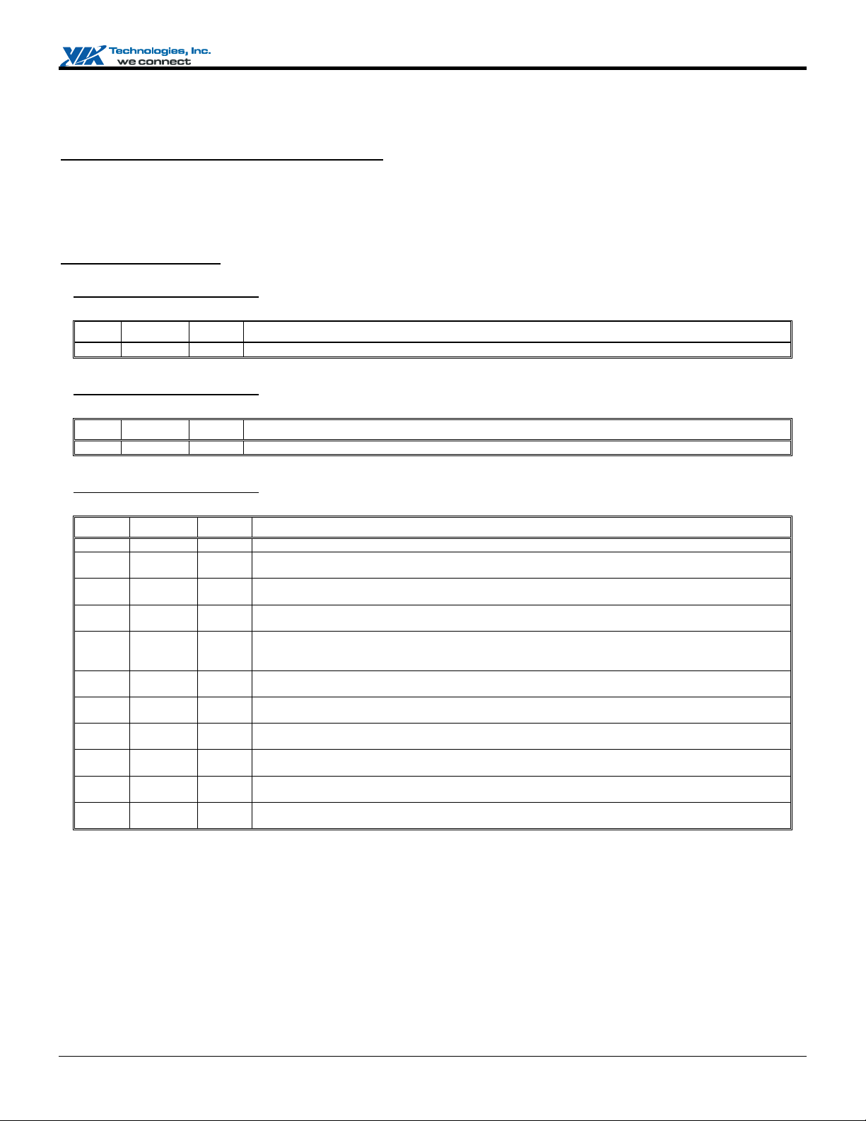
Control Registers for Integrated Graphics / Video Processor (C7-FFh)
Offset Address: C7h (D0F0) – Reserved
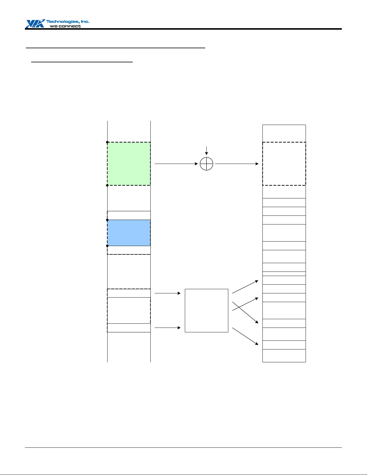
The integrated Graphics / Video processor uses up to two memory spaces; they are S.L. (System memory Local frame buffer)
and MMIO.
1. S.L. : Base address, RM0BS, is decided by D0F0 RxCF-C8, SL size is decided by D0F3 RxA1[6:4]
2. MMIO : Base address, RM1BS, is decided by D0F0 RxD7-D0, MMIO size is fixed to 128MB
PCI Address Space
M0LM =
RM0BS + RFBSZ
System Memory
Base Addr
.
nc
S.L.
I
S.L.
s
RM0BS
e
i
e
4 KB Page
d
4 KB Page
4 KB Page
4 KB Page
4 KB Page
4 KB Page
4 KB Page
M1LM =
RM1BS + 128MB
RM1BS
A
I
V
4 KB Page
MMIO
4 KB Page
e
T
4 KB Page
S.M.
4 KB Page
h
c
C
.....
nol
onf
.....
D
N
og
de
i
R
System
A
Memory
Mapping
Table
i
nt
qui
e
l
a
r
4 KB Page
Preliminary Revision 0.95, June 20, 2008 -10- North Module Register Descriptions
Page 19
VX800 / VX820 Series System Programming Manual
Offset Address: CB-C8h (D0F0)
GFX Shadow Memory Base 0 - S.L. Default Value: FFF0 0000h
Bit Attribute Default Description
31:4 RW FFF0 000h
3:0 RO 0h
Offset Address: CF-CCh (D0F0)
GFX Shadow Memory Base 1 - MMIO Default Value: FFF0 0000h
Bit Attribute Default Description
31:20 RW FFFh
19:0 RO 0
GFX’s Memory Base 0 Address[31:4] for S.L.
GFX’s Memory Base 0 Address[3:0] for S.L.
GFX’s Memory Base 1 Address[31:20] for MMIO
GFX’s Memory Base 1 Address[19:0] for MMIO
Offset Address: D0-FDh (D0F0) - Reserved
Offset Address: FEh (D0F0)
Internal GFX Related Control Default Value: 00h
Bit Attribute Default Description
7:5 RO 0
4 RW 0
3:2 RO 0
1 RW 0
0 RW 0
Offset Address: FFh (D0F0) - Reserved
Reserved
Enable Base VGA 16 bits Decode
0: All VGA alias range will be forwarded
1: Only forward base VGA range (Alias range will not be forwarded)
Reserved
Internal GFX Memory Space Access Control for MMIO (RM1BS~M1LM)
0: Disable. The cycle which belongs to GFX MMIO memory address range will not be passed to Internal GFX.
1: Enable. The cycle which belongs to GFX MMIO memory address range will be passed to Internal GFX.
Internal GFX Memory Space Access Control for S.L. (RM0BS~M0LM)
0: Disable. The cycle which belongs to S.L memory address range will not be passed to Internal GFX.
1: Enable. The cycle which belongs to S.L memory address range will be passed to Internal GFX.
nol
og
h
c
de
i
e
s
e
i
nt
e
nc
I
l
a
i
qui
.
d
e
r
T
I
A
onf
C
R
A
V
D
N
Preliminary Revision 0.95, June 20, 2008 -11- North Module Register Descriptions
Page 20

VX800 / VX820 Series System Programming Manual
Device 0 Function 1 (D0F1): Error Reporting
Header Registers (00-3Fh)
Offset Address: 01-00h (D0F1)
Vendor ID Default Value: 1106h
Bit Attribute Default Description
15:0 RO 1106h
Offset Address: 03-02h (D0F1)
Device ID Default Value: 1353h
Bit Attribute Default Description
15:0 RO 1353h
Offset Address: 05-04h (D0F1)
PCI Command Default Value: 0006h
Bit Attribute Default Description
15:10 RO 0
9 RO 0
8 RO 0
7 RO 0
6 RW 0
5 RO 0
4 RO 0
3 RO 0
2 RO 1b
1 RO 1b
0 RO 0
I
VIA Technologies ID Code
Device ID Code
.
nc
I
e
i
nt
R
s
a
i
qui
e
l
d
e
r
Reserved
Fast Back-to-Back Cycle Enable
Hardwired to 0 (Not supported)
SERR# Enable
Hardwired to 0 (Not supported)
Address / Data Stepping
Hardwired to 0 (Not supported)
Parity Error Response
0: Ignore parity errors
1: Perform parity check and take normal action on detected parity errors
VGA Palette Snooping
Hardwired to 0 (Not implemented)
Memory Write and Invalidate
Hardwired to 0 (Not supported)
Respond To Special Cycle
Hardwired to 0 (Does not monitor special cycles)
PCI Master Function
Hardwired to 1 (May behave as a bus master)
T
Memory Space Access
Hardwired to 1 (Responds to memory space access)
I/O Space Access
A
Hardwired to 0 (Does not respond to I/O space)
c
e
nol
h
onf
C
og
de
i
A
V
D
N
Preliminary Revision 0.95, June 20, 2008 -12- North Module Register Descriptions
Page 21
VX800 / VX820 Series System Programming Manual
Offset Address: 07-06h (D0F1)
PCI Status Default Value: 0200h
Bit Attribute Default Description
15 RO 0
14 RO 0
13 RO 0
12 RO 0
11 RO 0
10:9 RO 01b
8 RO 0
7 RO 0
6 RO 0
5 RO 0
4 RO 0
3:0 RO 0
Detected Parity Error
0: No parity error detected
1: Error detected in either address or data phase
Signaled System Error (SERR# asserted)
Received Master-Abort (except special cycle)
0: No abort received 1: Transaction aborted by the Master
Received Target-Abort
0: No abort received 1: Transaction aborted by the Target
Target-Abort Assertion
This chip does not assert Target-Abort
DEVSEL# Timing
00: Fast 01: Medium (default)
10: Slow 11: Reserved
Master Data Parity Error
This bit is set when bus master PERR# is asserted or observed ; Rx04[6] should be set first to enable this function.
Capable of Accepting Fast Back-to-back as A Target
Hardwired to 0 (Not implemented)
User Definable Features
Hardwired to 0
66 MHz Capable
Hardwired to 0 (Not implemented)
Support New Capability List
Reserved
e
i
s
nc
I
.
l
Offset Address: 08h (D0F1)
Revision ID Default Value: nnh
Bit Attribute Default Description
7:0 RO nnh
Offset Address: 0B-09h (D0F1)
Class Code Default Value: 06 0000h
Bit Attribute Default Description
23:0 RO 060000h
Offset Address: 0Ch (D0F1)
Class Code Default Value: 00h
Bit Attribute Default Description
7:0 RW 0
Offset Address: 0Dh (D0F1)
PCI Master Latency Timer Default Value: 00h
V
Chip Revision ID
A
I
e
Class Code
T
Cacheline Size
nol
h
c
onf
C
N
D
og
de
i
R
A
i
nt
qui
e
a
d
e
r
Bit Attribute Default Description
7:3 RO 0 PCI Bus Time Slice for CPU as a Master (in Unit of PCI Clocks)
2:0 RO 0
Preliminary Revision 0.95, June 20, 2008 -13- North Module Register Descriptions
Reserved
Bit [2:1] are programmable; however, it’s read as 0.
Page 22
VX800 / VX820 Series System Programming Manual
Offset Address: 0Eh (D0F1)
Header Type Default Value: 00 or 80h
Bit Attribute Default Description
7:0 RO 00 or 80h
Offset Address: 0Fh (D0F1)
Built In Self Test (BIST) Default Value: 00h
Bit Attribute Default Description
7 RO 0
6:0 RO 0
Header Type
Could be 80 when D0F0 Rx4F[0] = 1
BIST Support
Hardwired to 0 (Not supported)
Reserved
.
Offset Address: 10-2Bh (D0F1) – Reserved
Offset Address: 2D-2Ch (D0F1)
Subsystem Vendor ID Default Value: 0000h
Bit Attribute Default Description
15:0 RW1 0
Offset Address: 2F-2Eh (D0F1)
Subsystem ID Default Value: 0000h
Bit Attribute Default Description
15:0 RW1 0
Offset Address: 30-33h (D0F1) – Reserved
Offset Address: 34h (D0F1)
Capability Pointer Default Value: 00h
Subsystem Vendor ID
Subsystem ID
h
c
e
og
nol
de
i
s
e
i
nt
e
nc
I
l
a
i
qui
d
e
r
T
Bit Attribute Default Description
7:0 RO 0
Offset Address: 35-5Fh (D0F1) – Reserved
I
V
Capability List Pointer
A
An offset address from the start of the configuration space
onf
C
A
D
R
N
Preliminary Revision 0.95, June 20, 2008 -14- North Module Register Descriptions
Page 23
VX800 / VX820 Series System Programming Manual
Host Bus Error Report (60-6Fh)
Offset Address: 60h (D0F1)
Host Parity Status Default Value: 00h
Bit Attribute Default Description
7 RW1C 0
6 RW1C 0
5 RW1C 0
4 RW1C 0
3:0 RO 0
Offset Address: 61-67h (D0F1) – Reserved
Offset Address: 68h (D0F1)
Host Parity Command Default Value: 00h
Bit Attribute Default Description
7:4 RO 0
3 RW 0
2:0 RO 0
Offset Address: 69-FFh (D0F1) – Reserved
Host Address Parity Error Detected
0: Not detected
1: Detected
Host Data Parity Error Detected
0: Not detected
1: Detected
AGP Access Above 4G Detected
0: No above 4GB AGP cycles being detected
1: AGP Access Above 4GB detected
Host LOCK Cycle to PCI Detected
0: Not detected
1: Detected
Reserved
.
nc
I
s
e
i
l
Reserved
Parity Test Mode
0: Disable (normal mode) 1: Enable (invert the parity bit)
Reserved
nol
og
nt
i
a
d
e
r
h
c
e
de
i
qui
e
T
I
A
onf
C
R
A
V
D
N
Preliminary Revision 0.95, June 20, 2008 -15- North Module Register Descriptions
Page 24
VX800 / VX820 Series System Programming Manual
Device 0 Function 2 (D0F2): Host Bus Control
Header Registers (00-3Fh)
Offset Address: 01-00h (D0F2)
Vendor ID Default Value: 1106h
Bit Attribute Default Description
15:0 RO 1106h
Offset Address: 03-02h (D0F2)
Device ID Default Value: 2353h
Bit Attribute Default Description
15:0 RO 2353h
Offset Address: 05-04h (D0F2)
PCI Command Default Value: 0006h
Bit Attribute Default Description
15:10 RO 0
9 RO 0
8 RO 0
7 RO 0
6 RW 0
5 RO 0
4 RO 0
3 RO 0
2 RO 1b
1 RO 1b
0 RO 0
I
VIA Technologies ID Code
Device ID Code
.
nc
I
e
i
nt
R
s
a
i
qui
e
l
d
e
r
Reserved
Fast Back-to-Back Cycle Enable
Hardwired to 0 (Not supported)
SERR# Enable
Hardwired to 0 (Not supported)
Address / Data Stepping
Hardwired to 0 (Not supported)
Parity Error Response
0: Ignore parity errors
1: Perform parity check and take normal action on detected parity errors
VGA Palette Snooping
Hardwired to 0 (Not implemented)
Memory Write and Invalidate
Hardwired to 0 (Not supported)
Respond To Special Cycle
Hardwired to 0 (Does not monitor special cycles)
PCI Master Function
Hardwired to 1 (May behave as a bus master)
T
Memory Space Access
Hardwired to 1 (Responds to memory space access)
I/O Space Access
A
Hardwired to 0 (Does not respond to I/O space)
c
e
nol
h
onf
C
og
de
i
A
V
D
N
Preliminary Revision 0.95, June 20, 2008 -16- North Module Register Descriptions
Page 25
VX800 / VX820 Series System Programming Manual
Offset Address: 07-06h (D0F2)
PCI Status Default Value: 0200h
Bit Attribute Default Description
15 RW1C 0
14 RO 0 Signaled System Error (SERR# asserted)
13 RW1C 0 Received Master-Abort (except special cycle)
12 RW1C 0
11 RO 0
10:9 RO 01b
8 RW1C 0
7 RO 0
6 RO 0
5 RO 0
4 RO 0
3:0 RO 0
Detected Parity Error
0: No parity error detected
1: Error detected in either address or data phase
0: No abort received 1: Transaction aborted by the Master
Received Target-Abort
0: No abort received 1: Transaction aborted by the Target
Target-Abort Assertion
This chip does not assert Target-Abort.
DEVSEL# Timing
00: Fast 01: Medium
10: Slow 11: Reserved
Master Data Parity Error
This bit is set when bus Master PERR# is asserted or observed; Rx04[6] should be set first to enable this function.
Capable of Accepting Fast Back-to-back as a Target
Hardwired to 0 (Not implemented)
User Definable Features
Hardwired to 0
66 MHz Capable
Hardwired to 0 (Not implemented)
Support New Capability List
Reserved
e
i
s
nc
I
.
l
Offset Address: 08h (D0F2)
Revision ID Default Value: nnh
Bit Attribute Default Description
7:0 RO nnh
Offset Address: 0B-09h (D0F2)
Class Code Default Value: 06 0000h
Bit Attribute Default Description
23:0 RO 060000h
Offset Address: 0Ch (D0F2) – Reserved
Offset Address: 0Dh (D0F2)
PCI Master Latency Timer Default Value: 00h
V
Chip Revision ID
A
I
Class Code
T
nol
h
c
e
onf
C
D
og
de
i
R
A
i
nt
qui
e
a
d
e
r
Bit Attribute Default Description
7:3 RO 0 PCI Bus Time Slice for CPU as a Master (in Unit of PCI clocks)
2:0 RO 0
Offset Address: 0Eh (D0F2)
Header Type Default Value: 00 or 80h
Bit Attribute Default Description
7:0 RO 00 or 80h
Preliminary Revision 0.95, June 20, 2008 -17- North Module Register Descriptions
Reserved
Bit[2:1] is programmable; however, it’s read as 0.
Header Type
Could be 80 when D0F0 Rx4F[0] = 1
N
Page 26
VX800 / VX820 Series System Programming Manual
Offset Address: 0Fh (D0F2)
Built In Self Test (BIST) Default Value: 00h
Bit Attribute Default Description
7 RO 0
6:0 RO 0
Offset Address: 10-2Bh (D0F2) – Reserved
Offset Address: 2D-2Ch (D0F2)
Subsystem Vendor ID Default Value: 0000h
Bit Attribute Default Description
15:0 RW1 0
BIST Support
Hardwired to 0 (Not supported)
Reserved
Subsystem Vendor ID
.
Offset Address: 2F-2Eh (D0F2)
Subsystem ID Default Value: 0000h
Bit Attribute Default Description
15:0 RW1 0
Offset Address: 30-33h (D0F2) – Reserved
Subsystem ID
s
e
i
og
Offset Address: 34h (D0F2)
Capability Pointer Default Value: 00h
Bit Attribute Default Description
7:0 RO 0
Offset Address: 35-4Fh (D0F2) – Reserved
Capability List Pointer
An offset address from the start of the configuration space
c
e
nol
h
de
i
nt
e
nc
I
l
a
i
qui
d
e
r
T
V
I
A
onf
C
D
R
A
N
Preliminary Revision 0.95, June 20, 2008 -18- North Module Register Descriptions
Page 27
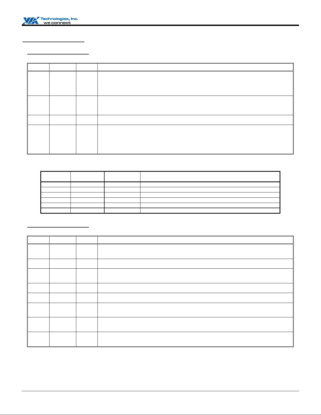
VX800 / VX820 Series System Programming Manual
Host CPU Control (50-5Fh)
Offset Address: 50h (D0F2)
Request Phase Control Default Value: n0h
Bit Attribute Default Description
7 RO dip
6 RO dip
5 RW 0
4:0 RW 0
Timer
Expire
No - No Snoop stall till PCI complete
No - Yes Normal Data Response
Yes No No Snoop stall till either arrival of new pending ADS or PCI complete
Yes No Yes Normal Data Response
Yes Yes No Defer/Retry Response
Yes Yes Yes Normal Data Response
Offset Address: 51h (D0F2)
CPU Interface Control – Basic Option Default Value: 00h
Bit Attribute Default Description
7 RW 0
6 RW 0
5 RW 0
V
4 RW 0
3 RW 0
2 RW 0
1 RW 0
0 RW 0
IOQ (In-Order Queue) Depth
0: 1 level
1: 12 levels (or 8 levels. Please refer to Rx55[7] for details.)
Default sets from the inverse of the SYSIDLE signal during system initialization. For strap pin information, check
the Strap Pin table for details.
Dual CPU
0: Single CPU 1: Dual CPU
Default sets from the inverse of the PDA1 signal during system initialization. For strap pin information, check the
Strap Pin table for details.
Fast ADS Assertion to DRAM Controller
0: Disable 1: Enable
Dynamic Defer Snoop Stall Count
Value for the Defer Snoop Stall Counter. The timer starts counting at the beginning of the snoop phase of C2P
cycle; it increases one for every 2 HCLKs. If the C2P cycle is pending when the timer expires, and there are
pending ADS, a Defer/Retry response will be replied to the host.
For medium decoding PCI slave device; the optimal value for bit[4:0] is 8.
nc
I
.
s
i
e
i
a
Action
l
d
New Pending
ADS
Table 2. Dynamic Defer Snoop Stall Table
PCI
Completion
og
e
nol
nt
r
h
c
e
de
i
qui
e
T
I
Fast Ready for CPU Memory Read Cycle
0: Disable. Wait until all 8QWs are received before DRDY assertion.
1: Enable. DRDY assertion timing is set up through Rx60-67.
A
Read Around Write
0: Disable 1: Enable
Host Memory Request Queue Control (DXQ)
0: Disable pipeline ADS assertion
1: Enable pipeline ADS assertion to DRAM controller
CPU to PCI Read Defer
0: Disable 1: Enable
2-Entry Defer / Retry Queue Usage
0: Disable 1: Enable
2-Entry Defer / Retry Queue Sharing Policy
0: One entry for each host processor
1: Each entry is shared by the two host processors
Special Cycle Will Be Regarded as Posted Write Cycles
0: As posted write cycles
1: As non-posted write cycles
IOW Cycles Can Be Deferred
0: IOW cycles will be deferred
1: Cannot be deferred, only retried
onf
C
D
N
R
A
Preliminary Revision 0.95, June 20, 2008 -19- North Module Register Descriptions
Page 28
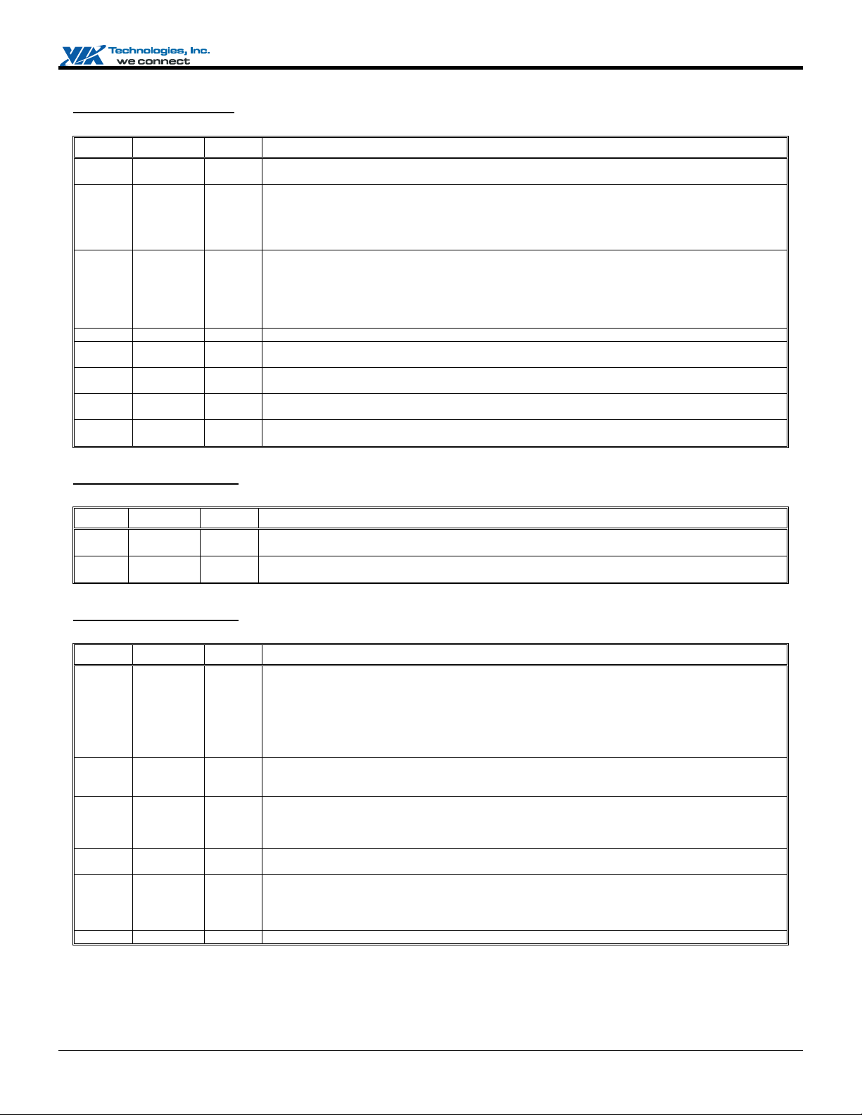
VX800 / VX820 Series System Programming Manual
Offset Address: 52h (D0F2)
CPU Interface Control – Advanced Option Default Value: 00h
Bit Attribute Default Description
7 RW 0
6 RW 0
5 RO 0
4 RO 0
3 RW 0
2 RW 0
1 RW 0
0 RW 0
CPU 0WS Read / Write DRAM for Back-to-Back Pipeline Access
0: Disable 1: Enable
HREQ (Host Continuous DRAM Ownership) / HPRI (Host High Priority DRAM Request) Assertion to
DRAM Controller
0: Disable
1: Enable assertion of HREQ / HPRI to DRAM controller for efficient memory utilization / faster memory data
access.
Enable Pull-up Termination of AGTL+ Output Buffer When Pulling GTL Bus Signal from Voltage Low to
Voltage High
0: Disable 1: Enable
Default sets from the inverse of the GPIO3 signal during system initialization. For strap pin information, check the
Strap Pin table for details.
Reserved
Write Retire Policy After 2 Writes
0: Disable 1: Enable
2-Level Defer Queue With Lock Cycle
0: Disable 1: Enable
Consecutive Speculative Read
0: Disable 1: Enable
Speculative Read
0: Disable 1: Enable
e
I
s
nc
.
i
Offset Address: 53h (D0F2)
Arbitration Default Value: 00h
Bit Attribute Default Description
7:4 RW 0 Host Occupancy Timer (in unit of 4 HCLKs)
3:0 RW 0 Master Occupancy Timer (in unit of 4 HCLKs)
Host Occupancy timer guarantees a time slot of bit[7:4] * 4 HCLK for pipelined CPU’s ADS.
Master Occupancy timer guarantees a time slot of bit[3:0] *4 HCLK for pending master requests.
nol
h
c
Offset Address: 54h (D0F2)
Miscellaneous Control 1 Default Value: n0h
Bit Attribute Default Description
7:5 RO dip
A
I
V
4 RW 0
3 RW 0
2 RW 0
1 RW 0
0 RO 0
e
T
CPU FSB Frequency (Powell)
000: 100MHz 001: 133MHz
010: 166MHz (auto mode only) 011: 200MHz
Others: Reserved
Default sets from the GPIO12 and CSTATE1signals during system initialization. For strap pin information, check
the Strap Pin table for details.
Host 8QW Burst Memory Access
0: Disable (not supported) 1: Enable
This bit must be set to 1.
Host-Memory DRDY Assertion 1T Adjustment
0: Normal mode, no adjustment 1: Special mode
This bit’s setting should follow Rx60 - Rx67 settings. Check Rx55[1] for details of DRDY assertion adjustment.
PCI Master 8QW Burst Memory Access
0: Disable 1: Enable
Memory-to-Host Conversion Circuit
0: Transparent mode 1: Sync 1T in certain clock phases
Transparent mode (default operating mode) is faster than Sync mode.
Reserved
onf
C
N
og
nt
de
i
e
R
A
D
l
a
i
qui
d
e
r
Preliminary Revision 0.95, June 20, 2008 -20- North Module Register Descriptions
Page 29
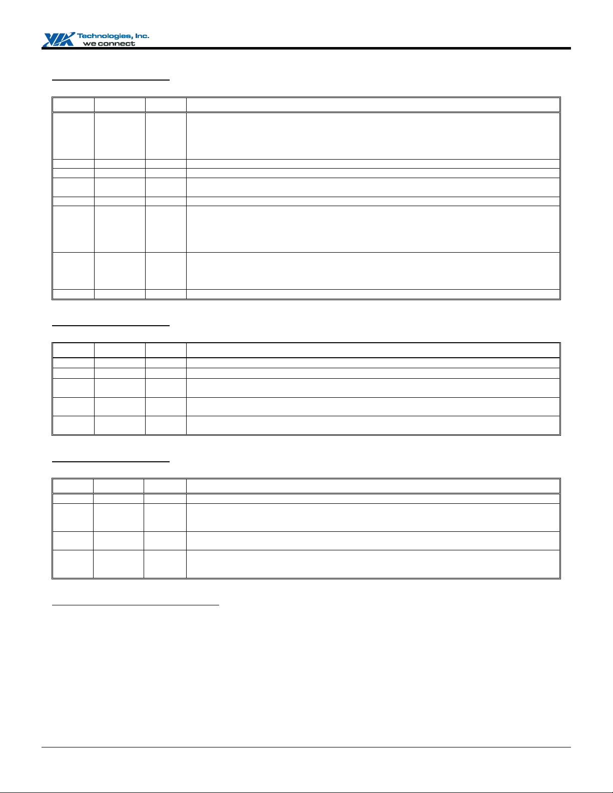
VX800 / VX820 Series System Programming Manual
Offset Address: 55h (D0F2)
Miscellaneous Control 2 Default Value: 20h
Bit Attribute Default Description
7 RW 0
6 RO 0
5 RO 1b Reserved (Do not program)
4 RW 0
3 RO 0
2 RW 0
1 RW 0
0 RO 0
Host Interface IOQ Size
Rx50[7] Rx55[7] Host IF IOQ Size
0 x 1
1 1 8
1 0 12
Reserved
Early Read DRDY Assertion for Host Interface DRDY Table
0: 2T early 1: 3T early
Reserved
Enable Medium Threshold for Write Policy
0: Disable medium threshold
1: Add a medium threshold (defined by Rx56[7:4]), in Write Queue to enable earlier memory write.
Refers to Rx5D for write policy.
Host-Memory DRDY Assertion 2T Adjustment
0: 2T early 1: 2T late
This bit is effective when Rx54[3] is 1.
Reserved
s
nc
I
.
e
Offset Address: 56h (D0F2)
Write Policy 1 Default Value: 00h
Bit Attribute Default Description
7:4 RW 0
3 RO 0
2 RW 0
1 RW 0
0 RW 0
Offset Address: 57h (D0F2)
Calibration Function Default Value: 00h
Bit Attribute Default Description
7:3 RO 0
2 RW 0
I
V
1 RW 0
0 RW 0
Medium Threshold for Write Policy
Reserved
TL Request 1T Pipeline
0: Disable 1: Enable
P6IF Will Flush the Post-write Request When HBHIT Asserts
0: Disable 1: Enable
Treat TLPRI as High Priority for P2C Read Cycle in Acquiring Host Bus Ownership
0: Disable 1: Enable
c
nol
h
e
T
A
Reserved
Enable to Sample 4X HA/HREQ Signals Issued by The Processor in V4 Bus
This bit must be set to 1.
0: Disable (not supported) 1: Enable
Auto-calibration Function of HDFWRING to Correct Noisy TE Due to Residual HDSTBP/HDSTBN
0: Disable 1: Enable
Fast TRDY Support
0: The chipset will never support fast TRDY assertion regardless of the setting of Rx96[3].
1: When Rx96[3] is set to 1,the chipset supports dynamical fast TRDY assertion in V4 bus.
onf
C
N
og
i
A
D
i
nt
de
R
a
i
qui
e
l
d
e
r
Offset Address: 58h (D0F2) – Reserved
Preliminary Revision 0.95, June 20, 2008 -21- North Module Register Descriptions
Page 30
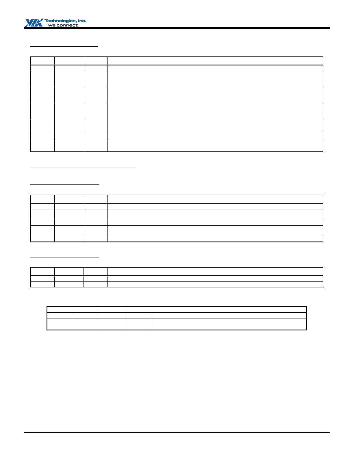
VX800 / VX820 Series System Programming Manual
Offset Address: 59h (D0F2)
CPU Miscellaneous Control 1 Default Value: 08h
Bit Attribute Default Description
7 RO 0
6 RW 0
5:4 RW 0
3 RW 1b
2 RW 0
1 RO 0
0 RW 0
Offset Address: 5A-5Bh (D0F2) – Reserved
Offset Address: 5Ch (D0F2)
CPU Miscellaneous Control 2 Default Value: 00h
Bit Attribute Default Description
7:5 RO 0
4 RW 0
3:2 RO 0
1 RW 0
0 RO 0
Offset Address: 5Dh (D0F2)
Write Policy 2 Default Value: 00h
Bit Attribute Default Description
7:4 RW 0
3:0 RW 0
I
V
Rx51[6] Rx52[3] Rx5D[7:4] Rx5D[3:0] Write Policy
1 0 x x Will not handle write request until FIFO is full
1 1 4 2 Will start processing write request when write request count reaches Rx5D[7:4],
Reserved
Enable 8QW SDRAM Access for Direct Frame Buffer
0: 8QW access for direct frame buffer is disabled
1: 8QW access for direct frame buffer is enabled
Warm CPU Reset (CPURST#) Duration Control
00: 475ns 01: 1050ns
10: 1425ns 11: 1905ns
Warm CPU Reset (CPURST#) Trigger
Write 0 1 transition will trigger warm CPURST#
Firmware will have to reset this bit to “0” before trigger another CPURST#.
Sync DADS for Better DRAM Access Timing
0: Disable 1: Enable
Report Delay Mode of HCLK
0: Disable 1: Enable
Lowest-Priority IPI (Inter-Processor Interrupt) Support
0: Disable 1: Enable
s
e
i
Reserved
APIC Data Bit 11 (D11) Mask
0: D11 is not masked 1: D11 is masked to 0
Reserved
APIC Cluster Mode Support
0: Disable 1: Enable
Reserved
nol
h
c
og
nt
de
i
e
a
i
qui
e
T
Write Request High Threshold
A
Write Request Low Threshold
C
onf
R
A
Table 3. CPU Write Request Policy
D
N
and stop processing write request when write request count drops to Rx5D[3:0].
.
nc
I
l
d
e
r
Preliminary Revision 0.95, June 20, 2008 -22- North Module Register Descriptions
Page 31

VX800 / VX820 Series System Programming Manual
Offset Address: 5Eh (D0F2)
Bandwidth Timers Default Value: 00h
Bit Attribute Default Description
7:4 RW 0
3:0 RW 0
Offset Address: 5Fh (D0F2)
CPU Miscellaneous Control 3 Default Value: 00h
Bit Attribute Default Description
7 RO 0
6 RW 0
5:3 RO 0
2 RW 0
1 RW 0
0 RO 0
Rx5F[2] Rx5F[1] Host / DRAM Bandwidth Setting Policy
0 0 Disable the new DRAM/Host Bandwidth Arbiter
0 1 Use the DRAM Bandwidth Timer only
1 0 Use the HOST Bandwidth Timer only
1 1 Dynamically toggles between the two timers: Host and DRAM bandwidth timers. Both timers,
Host Bandwidth Timer
DRAM Bandwidth Timer
Reserved
Enable Reorder Retry Queue
0: Retried CPU transaction always complete in order
1: Allow second entry of retried (IOW/MEMW) transaction to complete before first queued entry
Reserved
Host Bandwidth Restriction
0: Disable 1: Enable
Host Bandwidth Timer is set up by Rx5E[7:4].
DRAM Bandwidth Restriction
0: Disable 1: Enable
DRAM Bandwidth Timer is set up by Rx5E[3:0].
Reserved
I
s
nc
.
e
Table 4. Host / DRAM Bandwidth Policy
i
l
og
Rx5E[7:4] and Rx5E[3:0] are used by the arbitration logic.
nol
nt
i
a
d
e
r
h
c
e
de
i
qui
e
T
I
A
onf
C
R
A
V
D
N
Preliminary Revision 0.95, June 20, 2008 -23- North Module Register Descriptions
Page 32

VX800 / VX820 Series System Programming Manual
Host Interface DRDY Timing Control (60-6Fh)
Offset Address: 60h (D0F2)
DRDY Timing Control 1 for Read Line Access Default Value: 00h
Bit Attribute Default Description
7:6 RW 0
5:4 RW 0
3:2 RW 0
1:0 RW 0
Offset Address: 61h (D0F2)
DRDY Timing Control 2 for Read Line Access Default Value: 00h
Bit Attribute Default Description
7:6 RW 0
5:4 RW 0
3:2 RW 0
1:0 RW 0
Offset Address: 62h (D0F2)
DRDY Timing Control 3 for Read Line Access Default Value: 00h
Bit Attribute Default Description
7:4 RO 0
3:2 RW 0
1:0 RW 0
Offset Address: 63h (D0F2)
DRDY Timing Control 1 for Read Quad-Word Access Default Value: 00h
Bit Attribute Default Description
7:6 RW 0
V
5:4 RW 0
3:2 RW 0
1:0 RW 0
Read Line Phase 4 Wait State
The number of wait states should be added into this phase. (n wait states mean nT delay)
Read Line Phase 3 Wait State
See the bit descriptions above.
Read Line Phase 2 Wait State
See the bit descriptions above.
Read Line Phase 1 Wait State
See the bit descriptions above.
.
nc
Read Line Phase 8 Wait State
Refer to Rx60[7:6] bit descriptions for details.
Read Line Phase 7 Wait State
Refer to Rx60[7:6] bit descriptions for details.
Read Line Phase 6 Wait State
Refer to Rx60[7:6] bit descriptions for details.
Read Line Phase 5 Wait State
Refer to Rx60[7:6] bit descriptions for details.
og
e
i
s
i
I
l
a
d
e
nol
Reserved
Read Line Phase 10 Wait State
Refer to Rx60[7:6] bit descriptions for details.
Read Line Phase 9 Wait State
Refer to Rx60[7:6] bit descriptions for details.
e
c
h
de
i
nt
qui
e
r
T
I
A
Read QW Phase 4 Wait State
Refer to Rx60[7:6] bit descriptions for details.
Read QW Phase 3 Wait State
Refer to Rx60[7:6] bit descriptions for details.
Read QW Phase 2 Wait State
Refer to Rx60[7:6] bit descriptions for details.
Read QW Phase 1 Wait State
Refer to Rx60[7:6] bit descriptions for details.
onf
C
D
N
R
A
Preliminary Revision 0.95, June 20, 2008 -24- North Module Register Descriptions
Page 33

VX800 / VX820 Series System Programming Manual
Offset Address: 64h (D0F2)
DRDY Timing Control 2 for Read Quad-Word Access Default Value: 00h
Bit Attribute Default Description
7:6 RW 0
5:4 RW 0
3:2 RW 0
1:0 RW 0
Offset Address: 65h (D0F2)
DRDY Timing Control 3 for Read Quad-Word Access Default Value: 00h
Bit Attribute Default Description
7:4 RO 0
3:2 RW 0
1:0 RW 0
Offset Address: 66h (D0F2)
Burst DRDY Timing Control 1 for Read Line Access Default Value: 00h
Bit Attribute Default Description
7 RW 0
6 RW 0
5 RW 0
4 RW 0
3 RW 0
2 RW 0
1 RW 0
0 RW 0
I
Read QW Phase 8 Wait State
Refer to Rx60[7:6] bit descriptions for details.
Read QW Phase 7 Wait State
Refer to Rx60[7:6] bit descriptions for details.
Read QW Phase 6 Wait State
Refer to Rx60[7:6] bit descriptions for details.
Read QW Phase 5 Wait State
Refer to Rx60[7:6] bit descriptions for details.
Reserved
Read QW Phase 10 Wait State
Refer to Rx60[7:6] bit descriptions for details.
Read QW Phase 9 Wait State
Refer to Rx60[7:6] bit descriptions for details.
Phase 8 Wait State
Refer to Rx60[7:6] bit descriptions for details.
Phase 7 Wait State
Refer to Rx60[7:6] bit descriptions for details.
Phase 6 Wait State
Refer to Rx60[7:6] bit descriptions for details.
Phase 5 Wait State
Refer to Rx60[7:6] bit descriptions for details.
Phase 4 Wait State
Refer to Rx60[7:6] bit descriptions for details.
Phase 3 Wait State
Refer to Rx60[7:6] bit descriptions for details.
T
Phase 2 Wait State
Refer to Rx60[7:6] bit descriptions for details.
Phase 1 Wait State
A
Refer to Rx60[7:6] bit descriptions for details.
c
e
nol
h
onf
C
og
de
i
R
A
s
e
i
nt
e
nc
I
l
a
i
qui
.
d
e
r
Offset Address: 67h (D0F2)
Burst DRDY Timing Control 2 for Read Line Access Default Value: 00h
Bit Attribute Default Description
7:6 RO 0
5 RW 0
4 RW 0
3:0 RO 0
Preliminary Revision 0.95, June 20, 2008 -25- North Module Register Descriptions
V
Reserved
Phase 10 Wait State
Refer to Rx60[7:6] bit descriptions for details.
Phase 9 Wait State
Refer to Rx60[7:6] bit descriptions for details.
Reserved
D
N
Page 34

VX800 / VX820 Series System Programming Manual
Offset Address: 68h (D0F2)
APIC CPU Priority 0 Default Value: 00h
Bit Attribute Default Description
7:0 RO 0
Offset Address: 69h (D0F2)
APIC CPU Priority 1 Default Value: 00h
Bit Attribute Default Description
7:0 RO 0
Offset Address: 6Ah (D0F2)
APIC CPU Priority 2 Default Value: 00h
Priority of CPU ID#0
Priority of CPU ID#1
.
Bit Attribute Default Description
7:0 RO 0
Offset Address: 6Bh (D0F2)
APIC CPU Priority 3 Default Value: 00h
Bit Attribute Default Description
7:0 RO 0
Offset Address: 6Ch (D0F2)
APIC CPU Priority 4 Default Value: 00h
Bit Attribute Default Description
7:0 RO 0
Priority of CPU ID#2
Priority of CPU ID#3
Priority of CPU ID#4
nol
i
og
nt
e
s
i
nc
I
l
a
d
e
r
h
Offset Address: 6Dh (D0F2)
APIC CPU Priority 5 Default Value: 00h
c
e
Bit Attribute Default Description
7:0 RO 0
Offset Address: 6Eh (D0F2)
APIC CPU Priority 6 Default Value: 00h
Bit Attribute Default Description
7:0 RO 0
I
V
T
Priority of CPU ID#5
A
Priority of CPU ID#6
onf
C
D
de
i
A
qui
e
R
N
Offset Address: 6Fh (D0F2)
APIC CPU Priority 7 Default Value: 00h
Bit Attribute Default Description
7:0 RO 0
Preliminary Revision 0.95, June 20, 2008 -26- North Module Register Descriptions
Priority of CPU ID#7
Page 35

VX800 / VX820 Series System Programming Manual
Host AGTL+ I/O Circuit (70–8Fh)
Offset Address: 70h (D0F2)
Host Address Pad Pullup Driving Default Value: 00h
Bit Attribute Default Description
7 RO 0
6:4 RW 0
3 RO 0
2:0 RW 0
Offset Address: 71h (D0F2)
Host Address Pad Pulldown Driving Default Value: 00h
Bit Attribute Default Description
7 RO 0
6:4 RW 0
3 RO 0
2:0 RW 0
Reserved
Address Strobe Pad Pullup Driving – (HADSTB1#, HADSTB0#)
Reserved
Address Pad Pullup Driving – (HA[30, 16:03]#, HREQ[2:0]#)
Reserved
Address Strobe Pad Pulldown Driving – (HADSTB1#, HADSTB0#)
Reserved
Address Pad Pulldown Driving – (HA[30, 16:03]#, HREQ[2:0]#)
nc
.
I
Offset Address: 72h (D0F2)
Host Data Pad (4x) Pullup Driving Default Value: 00h
Bit Attribute Default Description
7 RW 0
6:4 RW 0
3 RW 0
2:0 RW 0
Offset Address: 73h (D0F2)
Host Data Pad (4x) Pulldown Driving Default Value: 00h
Reserved
4X Data Strobe Pad Pulldup Driving – (HDSTB[3:0]N#, HDSTB[3:0]P#)
Reserved
4X Data Pad Pullup Driving – (HD[63:0]#, HDBI[3:0]#)
og
nol
s
e
i
nt
i
l
a
d
e
r
h
Bit Attribute Default Description
7 RO 0
6:4 RW 0
3 RO 0
2:0 RW 0
Offset Address: 74h (D0F2)
Host Data / Address Interface Timing Control Default Value: 00h
Bit Attribute Default Description
7:6 RO 0
5 RW 0
4 RW 0
3:2 RO 0
1:0 RW 0
I
V
Reserved
4X Data Strobe Pad Pulldown Driving – (HDSTB[3:0]N#, HDSTB[3:0]P#)
Reserved
T
4X Data Pad Pulldown Driving – (HD[63:0]#, HDBI[3:0]#)
A
Reserved
Output Stagger Delay on HD[63:48]#, HD[31:16]#, HDBI[3,1]#, HDSTB3P#, HDSTB3N#, HDSTB1P#,
HDSTB1N#
0: No delay 1: 0.5 ns delay
HA30# Output Stagger Delay
0: No delay 1: 0.5 ns delay
Reserved
AGTL+ 1X Pad Extra Output Delay
00: No delay 01: 0.1 ns
10: 0.2 ns 11: 0.3 ns
c
e
onf
C
D
N
de
i
A
qui
e
R
Preliminary Revision 0.95, June 20, 2008 -27- North Module Register Descriptions
Page 36

VX800 / VX820 Series System Programming Manual
Offset Address: 75h (D0F2)
AGTL+ I/O Configuration 1 Default Value: 00h
Bit Attribute Default Description
7:6 RO 0
5 RW 0
4:3 RO 0
2 RW 0
1 RW 0
0 RO 0
Equivalent Circuit Illustration of GTL IO Buffer Output Mode Control:
All the information is based on Rx52[5] and Rx75[2] / Rx75[1]
Rx52[5] attaches to PEN port of GTL IO Buffer (for DATA & STROBE)
Rx75[2] attaches to TR port of GTL IO Buffer (for STROBE)
Rx75[1] attaches to TR port of GTL IO Buffer (for DATA)
Reserved
AGTL+ Slew Rate
0: Disable 1: Enable
Reserved
Behavior Control of AGTL+ Pull-up Termination for STROBE Signal
0: Pull-up termination of AGTL+ output buffer will be open-drained when driving STROBE signal of GTL bus
from high to low.
1: Pull-up termination of AGTL+ output buffer will function as a current –sharing impedance, as well as the other
pull-up termination of AGTL+ output buffer at the processor side when driving STROBE signal of GTL bus from
high to low to uplift the low voltage of STORBE signal of GTL bus.
Behavior Control of AGTL+ Pull-up Termination for DATA Signal
0: Pull-up termination of AGTL+ output buffer will be open-drained when driving DATA signal of GTL bus
from high to low.
1: Pull-up termination of AGTL+ output buffer will function as a current –sharing impedance, as well as the other
pull-up termination of AGTL+ output buffer at the processor side when driving DATA signal of GTL bus from
high to low to uplift the low voltage of DATA signal of GTL bus.
Reserved
nc
I
.
s
e
i
l
og
i
a
d
e
nol
nt
r
h
c
e
de
i
qui
e
T
Drive GTL bus signal
from voltage-high to
voltage-low
I
A
onf
C
R
A
V
D
N
Drive GTL bus signal
from voltage-low to
voltage-high
Preliminary Revision 0.95, June 20, 2008 -28- North Module Register Descriptions
Page 37

VX800 / VX820 Series System Programming Manual
Offset Address: 76h (D0F2)
AGTL+ I/O Configuration 2 Default Value: 0Ch
Bit Attribute Default Description
7:4 RO 0
3 RW 1b
2 RO 1b Reserved (Do not program)
1 RW 0
0 RW 0
Reserved
Power Down Input Comparators of AGTL+ IO Buffers When Entering S3 State (Suspend to DRAM State)
0: Disable 1: Enable
Disable DBI Function
0: Enable DBI
1: Disable DBI (DBI always high including DBI double-check)
DBI Functional Mode
0: Minimize data change count (through data comparison with previous data)
1: Minimize AGTL+ pulldown count
Offset Address: 77h (D0F2) – Reserved
Offset Address: 78h (D0F2)
2X AGTL+ Auto Compensation Offset Default Value: 00h
Bit Attribute Default Description
7:4 RW 0
3:0 RW 0
Offset Address: 79h (D0F2)
4X AGTL+ Auto Compensation Offset Default Value: 00h
Bit Attribute Default Description
7:4 RW 0
3:0 RW 0
Offset Address: 7Ah (D0F2)
AGTL Compensation Status Default Value: 00h
Bit Attribute Default Description
7 RW 0
6:4 RO 0
3 RO 0
2:0 RO 0
I
2X AGTL+ IO Pad Driving Offset to Compensation PMOS Result
2X AGTL+ IO Pad Driving Offset to Compensation NMOS Result
og
4X AGTL+ IO Pad Driving Offset to Compensation PMOS Result
4X AGTL+ IO Pad Driving Offset to Compensation NMOS Result
nol
h
c
de
i
e
Auto-Compensation Driving
T
0: Disable auto mode 1: Enable auto mode
GTL Compensation Result
Reserved
A
GTL Compensation Result
onf
C
A
s
e
i
nt
e
R
nc
I
l
a
i
qui
.
d
e
r
V
D
N
Preliminary Revision 0.95, June 20, 2008 -29- North Module Register Descriptions
Page 38

VX800 / VX820 Series System Programming Manual
Offset Address: 7Bh (D0F2)
Input Host Address / Host Strobe Delay Control for HA Group Default Value: 18h
HA lower address group definitions:
HA30#
HA[16:03]#
HREQ[2:0]#
Bit Attribute Default Description
7 RO 0
6:4 RW 001b
3 RO 1b Reserved (Do not program)
2:0 RO 0
Offset Address: 7Ch (D0F2)
Output Delay Control of PAD for HA Group Default Value: 00h
Bit Attribute Default Description
7:6 RO 0
5:4 RW 0
3:2 RW 0
1:0 RW 00b
Offset Address: 7Dh (D0F2)
Host Address / Address Clock Output Delay Control Default Value: AAh
Bit Attribute Default Description
7:6 RW 10b
I
V
5:4 RW 10b
3:0 RO 1010b Reserved (Do not program)
Reserved
Host Address Input Delay Relative to Host Address Strobe for HA Lower Address Group
000: delay(data) = delay(strobe) – 200 ps
001: delay(data) = delay(strobe) – 150 ps
010: delay(data) = delay(strobe) – 100 ps
011: delay(data) = delay(strobe) – 50 ps
100: delay(data) = delay(strobe)
101: delay(data) = delay(strobe) + 50 ps
110: delay(data) = delay(strobe) + 100 ps
111: delay(data) = delay(strobe) + 150 ps
Reserved
nc
.
I
s
e
i
Reserved
HA[30, 16:03]#,HREQ[2:0]# Extra Delay for Output
00: 0 ps 01: 100 ps
10: 200 ps 11: 300 ps
HADSTB1# Extra Delay for Output
00: 0 ps 01: 100 ps
10: 200 ps 11: 300 ps
HADSTB0# Extra Delay for Output
00: 0 ps 01: 100 ps
10: 200 ps 11: 300 ps
nol
h
c
e
og
nt
de
i
e
l
a
i
qui
d
e
r
T
Output Delay of HA Lower Address Group Signals
A
Delay the output at the physical macro before driven into the host bus.
00: – 150 ps
01: 0 ps
10: 150 ps
11: 300 ps
The suggested value is 01b.
Output Delay of HADSTB0# Signal
Delay the output at the physical macro before driven into the host bus.
00: – 150 ps
01: 0 ps
10: 150 ps
11: 300 ps
The suggested value is 01b.
onf
C
D
N
R
A
Preliminary Revision 0.95, June 20, 2008 -30- North Module Register Descriptions
Page 39

VX800 / VX820 Series System Programming Manual
Offset Address: 7Eh (D0F2)
Host Address CKG Rising / Falling Time Control Default Value: 00h
Bit Attribute Default Description
7:6 RW 00b
5:4 RW 00b
3:0 RO 0
* : Refer to the HA lower address group definitions of Rx7B.
Offset Address: 7Fh (D0F2)
Host Address Clock CKG Rising / Falling Time Control Default Value: 00h
Bit Attribute Default Description
7:6 RW 00b
5:4 RW 00b
3:0 RO 0
Offset Address: 80h (D0F2)
Host Data / Strobe Input Delay Control 1 Default Value: 33h
Bit Attribute Default Description
7 RO 0
6:4 RW 011b
I
V
3 RO 0
2:0 RW 011b
Falling Time Output Delay of HA Lower Address Group Signals*
Delay the output at the physical macro before driven into the host bus.
00: Typical, falling edge transition time < 50 ps
01: Falling edge transition time: 100 ps
10: Falling edge transition time: 200 ps
11: Falling edge transition time: 300 ps
Rising Time Output Delay of HA Lower Address Group Signals*
Delay the output at the physical macro before driven into the host bus.
00: Typical, rising edge transition time < 50 ps
01: Rising edge transition time: 100 ps
10: Rising edge transition time: 200 ps
11: Rising edge transition time: 300 ps
Reserved
I
s
HASTB0N# Falling Time Delay
00: Typical, falling edge transition time < 50 ps
01: Falling edge transition time: 100 ps
10: Falling edge transition time: 200 ps
11: Falling edge transition time: 300 ps
HADSTB0# Falling Time Delay
00: Typical, falling edge transition time < 50 ps
01: Falling edge transition time: 100 ps
10: Falling edge transition time: 200 ps
11: Falling edge transition time: 300 ps
Reserved
nol
og
e
i
a
i
nt
h
c
e
de
i
qui
e
T
Reserved
Host Data Input Delay Relative to Host Data Strobe for HD/HDBI Group 1
000: delay(data) = delay(strobe) – 200 ps
A
001: delay(data) = delay(strobe) – 150 ps
010: delay(data) = delay(strobe) – 100 ps
011: delay(data) = delay(strobe) – 50 ps
100: delay(data) = delay(strobe)
101: delay(data) = delay(strobe) + 50 ps
110: delay(data) = delay(strobe) + 100 ps
111: delay(data) = delay(strobe) + 150 ps
Reserved
Host Data Input Delay Relative to Host Data Strobe for HD/HDBI Group 0
000: delay(data) = delay(strobe) – 200 ps
001: delay(data) = delay(strobe) – 150 ps
010: delay(data) = delay(strobe) – 100 ps
011: delay(data) = delay(strobe) – 50 ps
100: delay(data) = delay(strobe)
101: delay(data) = delay(strobe) + 50 ps
110: delay(data) = delay(strobe) + 100 ps
111: delay(data) = delay(strobe) + 150 ps
onf
C
D
N
R
A
.
nc
l
d
e
r
Preliminary Revision 0.95, June 20, 2008 -31- North Module Register Descriptions
Page 40

VX800 / VX820 Series System Programming Manual
Offset Address: 81h (D0F2)
Host Data / Strobe Input Delay Control 2 Default Value: 33h
Bit Attribute Default Description
7 RO 0
6:4 RW 011b
3 RO 0
2:0 RW 011b
Reserved
Host Data Input Delay Relative to Host Data Strobe for HD/HDBI Group 3
000: delay(data) = delay(strobe) – 200 ps
001: delay(data) = delay(strobe) – 150 ps
010: delay(data) = delay(strobe) – 100 ps
011: delay(data) = delay(strobe) – 50 ps
100: delay(data) = delay(strobe)
101: delay(data) = delay(strobe) + 50 ps
110: delay(data) = delay(strobe) + 100 ps
111: delay(data) = delay(strobe) + 150 ps
Reserved
Host Data Input Delay Relative to Host Data Strobe for HD/HDBI Group 2
000: delay(data) = delay(strobe) – 200 ps
001: delay(data) = delay(strobe) – 150 ps
010: delay(data) = delay(strobe) – 100 ps
011: delay(data) = delay(strobe) – 50 ps
100: delay(data) = delay(strobe)
101: delay(data) = delay(strobe) + 50 ps
110: delay(data) = delay(strobe) + 100 ps
111: delay(data) = delay(strobe) + 150 ps
nc
I
s
.
e
Offset Address: 82h (D0F2)
Output Delay of PAD for HDSTB Default Value: 33h
Bit Attribute Default Description
7:6 RW 00b
5:4 RW 11b
3:2 RW 00b
1:0 RW 11b
HDSTB3P#, HDSTB3N# Extra Output Delay
00: 0ps 01: 100ps
10: 200ps 11: 300ps
HDSTB2P#, HDSTB2N# Extra Output Delay
HDSTB1P#, HDSTB1N# Extra Output Delay
HDSTB0P#, HDSTB0N# Extra Output Delay
nol
h
c
Offset Address: 83h (D0F2)
Output Delay of PAD for HD Default Value: 33h
Bit Attribute Default Description
7:6 RW 00b
A
5:4 RW 11b
3:2 RW 00b
1:0 RW 11b
I
V
e
T
HD[63:48]#, HDBI3# Extra Output Delay
00: 0ps 01: 100ps
10: 200ps 11: 300ps
HD[47:32]#, HDBI2# Extra Output Delay
HD[31:16]#, HDBI1# Extra Output Delay
HD[15:00]#, HDBI0# Extra Output Delay
onf
C
og
i
A
D
i
nt
de
R
a
i
qui
e
l
d
e
r
N
Preliminary Revision 0.95, June 20, 2008 -32- North Module Register Descriptions
Page 41

VX800 / VX820 Series System Programming Manual
Offset Address: 84h (D0F2)
Host Data / Strobe CKG Control (Group 0) Default Value: 00h
Bit Attribute Default Description
7:6 RW 00b
5:4 RW 00b
3:2 RW 00b
1:0 RW 00b
Falling Time Output Delay of HDSTB0N# Signal
00: Typical, falling edge transition time < 50 ps
01: Falling edge transition time: 100 ps
10: Falling edge transition time: 200 ps
11: Falling edge transition time: 300 ps
Falling Time Output Delay of HDSTB0P# Signal
00: Typical, falling edge transition time < 50 ps
01: Falling edge transition time: 100 ps
10: Falling edge transition time: 200 ps
11: Falling edge transition time: 300 ps
Falling Time Output Delay of HD/HDBI Group 0 Signals
Delay the output at the physical macro before driven into the host bus.
00: Typical, falling edge transition time < 50 ps
01: Falling edge transition time: 100 ps
10: Falling edge transition time: 200 ps
11: Falling edge transition time: 300 ps
Rising Time Output Delay of HD/HDBI Group 0 Signals
Delay the output at the physical macro before driven into the host bus.
00: Typical, rising edge transition time < 50 ps
01: Rising edge transition time: 100 ps
10: Rising edge transition time: 200 ps
11: Rising edge transition time: 300 ps
s
e
nc
I
i
.
Offset Address: 85h (D0F2)
Host Data / Strobe CKG Control (Group 1) Default Value: 00h
Bit Attribute Default Description
7:6 RW 00b
5:4 RW 00b
3:2 RW 00b
I
1:0 RW 00b
V
A
Falling Time Output Delay of HDSTB1N# Signal
00: Typical, falling edge transition time < 50 ps
01: Falling edge transition time: 100 ps
10: Falling edge transition time: 200 ps
11: Falling edge transition time: 300 ps
Falling Time Output Delay of HDSTB1P# Signal
00: Typical, falling edge transition time < 50 ps
01: Falling edge transition time: 100 ps
10: Falling edge transition time: 200 ps
T
11: Falling edge transition time: 300 ps
Falling Time Output Delay of HD/HDBI Group 1 Signals
Delay the output at the physical macro before driven into the host bus.
00: Typical, falling edge transition time < 50 ps
01: Falling edge transition time: 100 ps
10: Falling edge transition time: 200 ps
11: Falling edge transition time: 300 ps
Rising Time Output Delay of HD/HDBI Group 1 Signals
Delay the output at the physical macro before driven into the host bus.
00: Typical, rising edge transition time < 50 ps
01: Rising edge transition time: 100 ps
10: Rising edge transition time: 200 ps
11: Rising edge transition time: 300 ps
c
e
nol
h
onf
C
N
og
nt
de
i
e
R
A
D
l
a
i
qui
d
e
r
Preliminary Revision 0.95, June 20, 2008 -33- North Module Register Descriptions
Page 42

VX800 / VX820 Series System Programming Manual
Offset Address: 86h (D0F2)
Host Data / Strobe CKG Control (Group 2) Default Value: 00h
Bit Attribute Default Description
7:6 RW 00b
5:4 RW 00b
3:2 RW 00b
1:0 RW 00b
Falling Time Output Delay of HDSTB2N# Signal
00: Typical, falling edge transition time < 50 ps
01: Falling edge transition time: 100 ps
10: Falling edge transition time: 200 ps
11: Falling edge transition time: 300 ps
Falling Time Output Delay of HDSTB2P# Signal
00: Typical, falling edge transition time < 50 ps
01: Falling edge transition time: 100 ps
10: Falling edge transition time: 200 ps
11: Falling edge transition time: 300 ps
Falling Time Output Delay of HD/HDBI Group 2 Signals
Delay the output at the physical macro before driven into the host bus.
00: Typical, falling edge transition time < 50 ps
01: Falling edge transition time: 100 ps
10: Falling edge transition time: 200 ps
11: Falling edge transition time: 300 ps
Rising Time Output Delay of HD/HDBI Group 2 Signals
Delay the output at the physical macro before driven into the host bus.
00: Typical, rising edge transition time < 50 ps
01: Rising edge transition time: 100 ps
10: Rising edge transition time: 200 ps
11: Rising edge transition time: 300 ps
s
e
nc
I
i
.
Offset Address: 87h (D0F2)
Host Data / Strobe CKG Control (Group 3) Default Value: 00h
Bit Attribute Default Description
7:6 RW 00b
5:4 RW 00b
3:2 RW 00b
A
I
1:0 RW 00b
Offset Address: 88-8Fh (D0F2) – Reserved
V
Falling Time Output Delay of HDSTB3N# Signal
00: Typical, falling edge transition time < 50 ps
01: Falling edge transition time: 100 ps
10: Falling edge transition time: 200 ps
11: Falling edge transition time: 300 ps
Falling Time Output Delay of HDSTB3P# Signal
00: Typical, falling edge transition time < 50 ps
01: Falling edge transition time: 100 ps
10: Falling edge transition time: 200 ps
T
11: Falling edge transition time: 300 ps
Falling Time Output Delay of HD/HDBI Group 3 Signals
Delay the output at the physical macro before driven into the host bus.
00: Typical, falling edge transition time < 50 ps
01: Falling edge transition time: 100 ps
10: Falling edge transition time: 200 ps
11: Falling edge transition time: 300 ps
Rising Time Output Delay of HD/HDBI Group 3 Signals
Delay the output at the physical macro before driven into the host bus.
00: Typical, rising edge transition time < 50 ps
01: Rising edge transition time: 100 ps
10: Rising edge transition time: 200 ps
11: Rising edge transition time: 300 ps
c
e
nol
h
onf
C
N
og
nt
de
i
e
R
A
D
l
a
i
qui
d
e
r
Preliminary Revision 0.95, June 20, 2008 -34- North Module Register Descriptions
Page 43

VX800 / VX820 Series System Programming Manual
Miscellaneous Control (90–9Eh)
Offset Address: 90h (D0F2)
Miscellaneous Control 3 Default Value: 08h
Bit Attribute Default Description
7:6 RO 0
5 RW 0
4 RW 0
3 RO 1b Reserved (Do not program)
2 RO 0
1:0 RW 00b
Offset Address: 91-95h (D0F2) – Reserved
Offset Address: 96h (D0F2)
Miscellaneous Control 4 Default Value: 00h
Reserved
Disable Continuous Data Pop to Host Bus
0: Enable continuous data pop to host bus
1: Disable continuous data pop to host bus
Add One Pipe When Issuing Speculative Read
0: Disable 1: Enable
Reserved
Control DRAM Read Ready Signal
00: 2T early RRDY 01: 3T early RRDY
10: 4T early RRDY 11: 5T early RRDY
.
nc
I
s
e
Bit Attribute Default Description
7:4 RO 0
3 RW 0
2 RO 0
1 RW 0
0 RW 0 HDPWR# Assertion Control (Activate if bit 1is enabled)
Offset Address: 97h (D0F2)
APIC Related Control Default Value: 00h
Bit Attribute Default Description
7:2 RO 0
1 RW 0
I
0 RW 0 Redirect Lowest Priority APIC Requests to CPU0 (i.e. CPU0 is treated as the lowest priority processor)
V
Reserved
V4 Fast TRDY Mode
0: Disable 1: Enable
Reserved
HDPWR# Assertion Policy
0: Always assert HDPWR# (no gating)
1: Dynamic HDPWR# assertion (Dynamic gating)
0: Assert HDPWR# for both read / write cycles
1: Assert HDPWR# for read or APIC write cycles
nol
h
c
og
i
e
T
Reserved
A
Pipeline APIC / Master Transaction
0: APIC requests will not be pipelined with master requests.
1: APIC requests can be pipelined with normal master requests.
This bit must be set to 0.
0: Disable 1: Enable.
onf
C
A
D
N
i
nt
de
R
a
i
qui
e
l
d
e
r
Offset Address: 98-9Dh (D0F2) – Reserved
Offset Address: 9Eh (D0F2)
Miscellaneous Control 5 Default Value: 00h
Bit Attribute Default Description
7:1 RO 0
0 RW 0
Offset Address: 9F-FFh (D0F2) – Reserved
Preliminary Revision 0.95, June 20, 2008 -35- North Module Register Descriptions
Reserved
Miscellaneous Control
0: Turn-off unused pad in V4 bus
1: Turn-on unused pad in V4 bus
Page 44

VX800 / VX820 Series System Programming Manual
Device 0 Function 3 (D0F3): DRAM Bus Control
There are three DDR2 DRAM controllers in this chip.
- Channel A: It can be 64 or 32 bits decided by Rx6C[5], and can also be used as the system memory.
- Channel C: It is dedicated to 16 bits, and can also store still display data in the snapshot mode.
All registers in Device 0 Function 3 are implemented in Powell. For the register setting of DRAM channels, please refer to the
following table.
Table 5. Programming Setting for DRAM Channels
DRAM Mode
Channel A Channel C
64-bit N/A 1 0 0
32-bit N/A 1 1 0
64-bit 16-bit 0 0 1
32-bit 16-bit 0 1 1
DRAM channel selection and dynamic clock setting:
For Channel A only –
D0F3 Rx6C[2] = 1
D0F4 RxA2[6] = 1
D0F4 RxA2[5] = 1
Header Registers (00–3Fh)
Offset Address: 01-00h (D0F3)
Vendor ID Default Value: 1106h
Bit Attribute Default Description
15:0 RO 1106h
Offset Address: 03-02h (D0F3)
Device ID Default Value: 3353h
Vendor ID
c
e
T
Bit Attribute Default Description
15:0 RO 3353h
I
A
Device ID
C
Rx6C[2] Rx6C[5]
i
og
nol
h
de
i
onf
R
A
for Channel A
nc
I
s
e
l
a
i
nt
qui
e
RxDB[7]
.
d
e
r
V
D
N
Preliminary Revision 0.95, June 20, 2008 -36- North Module Register Descriptions
Page 45

VX800 / VX820 Series System Programming Manual
Offset Address: 05-04h (D0F3)
PCI Command Default Value: 0006h
Bit Attribute Default Description
15:10 RO 0
9 RO 0
8 RO 0
7 RO 0
6 RO 0
5 RO 0
4 RO 0
3 RO 0
2 RO 1b
1 RO 1b
0 RO 0
Reserved
Fast Back-to-Back Cycle Enable
Hardwired to 0 (Not supported)
SERR# Enable
Hardwired to 0 (Not supported)
Address / Data Stepping
Hardwired to 0 (Not supported)
Parity Error Response
0: Ignore parity errors
1: Perform parity check and take normal action on detected parity errors
VGA Palette Snooping
Hardwired to 0 (Not implemented)
Memory Write and Invalidate
Hardwired to 0 (Not supported)
Respond To Special Cycle
Hardwired to 0 (Does not monitor special cycles)
PCI Master Function
Hardwired to 1 (May behave as a bus master)
Memory Space Access
Hardwired to 1 (Responds to memory space access)
I/O Space Access
Hardwired to 0 (Does not respond to I/O space)
s
e
nc
I
i
.
Offset Address: 07-06h (D0F3)
PCI Status Default Value: 0200h
Bit Attribute Default Description
15 RW1C 0
14 RO 0 Signaled System Error (SERR# asserted)
13 RW1C 0 Received Master-Abort (except special cycle)
12 RW1C 0
11 RO 0
10:9 RO 01b
A
8 RW1C 0
7 RO 0
6 RO 0
5 RO 0
4 RO 0
3:0 RO 0
Offset Address: 08h (D0F3)
Revision ID Default Value: nnh
I
V
Detected Parity Error
0: No parity error detected
1: Error detected in either address or data phase
nol
h
0: No abort received 1: Transaction aborted by the Master
Received Target-Abort
0: No abort received 1: Transaction aborted by the Target
Target-Abort Assertion
T
This chip does not assert Target-Abort.
DEVSEL# Timing
00: Fast 01: Medium
10: Slow 11: Reserved
Master Data Parity Error
This bit is set when bus Master PERR# is asserted or observed; Rx04[6] should be set first to enable this
function.
Capable of Accepting Fast Back-to-back as a Target
Hardwired to 0 (Not implemented)
User Definable Features
Hardwired to 0
66 MHz Capable
Hardwired to 0 (Not implemented)
Support New Capability List
Reserved
c
e
onf
C
N
og
nt
de
i
e
R
A
D
l
a
i
qui
d
e
r
Bit Attribute Default Description
7:0 RO nnh
Preliminary Revision 0.95, June 20, 2008 -37- North Module Register Descriptions
Revision ID
Page 46

VX800 / VX820 Series System Programming Manual
Offset Address: 0B-09h (D0F3)
Class Code Default Value: 06 0000h
Bit Attribute Default Description
23:0 RO 060000h
Offset Address: 0Ch (D0F3) – Reserved
Offset Address: 0Dh (D0F3)
Latency Timer Default Value: 00h
Bit Attribute Default Description
7:0 RO 0
Offset Address: 0Eh (D0F3)
Header Type Default Value: 00h
Class Code
Latency Timer
.
nc
Bit Attribute Default Description
7:0 RO 0
Offset Address: 0Fh (D0F3)
Built In Self Test (BIST) Default Value: 00h
Bit Attribute Default Description
7:0 RO 0
Offset Address: 10-13h (D0F3) – Reserved
Offset Address: 2D-2Ch (D0F3)
Subsystem Vendor ID Default Value: 0000h
Bit Attribute Default Description
15:0 RW1 0
Offset Address: 2F-2Eh (D0F3)
Subsystem ID Default Value: 0000h
Bit Attribute Default Description
15:0 RW1 0
V
A
I
Header Type
BIST
c
e
Subsystem Vendor ID
T
C
Subsystem ID
nol
h
onf
e
i
og
nt
de
i
R
A
D
s
a
i
qui
e
I
l
d
e
r
Offset Address: 30-33h (D0F3) – Reserved
Offset Address: 34h (D0F3)
Capability Pointer Default Value: 00h
Bit Attribute Default Description
7:0 RO 0
Offset Address: 37-3Fh (D0F3) – Reserved
Preliminary Revision 0.95, June 20, 2008 -38- North Module Register Descriptions
Capability Pointer
N
Page 47

VX800 / VX820 Series System Programming Manual
DRAM Rank (Row) Ending / Beginning Address (40–4Fh)
Offset Address: 40h (D0F3)
DRAM Rank 0 Ending Address Default Value: 01h
Bit Attribute Default Description
7:0 RW 01h
Offset Address: 41h (D0F3)
DRAM Rank 1 Ending Address Default Value: 00h
Bit Attribute Default Description
7:0 RW 0
Offset Address: 42h (D0F3)
DRAM Rank 2 Ending Address Default Value: 00h
Bit Attribute Default Description
7:0 RW 0
Virtual Rank 0 Ending Address (Host Address Bits[33:26])
Virtual Rank 1 Ending Address (Host Address Bits[33:26])
.
Virtual Rank 2 Ending Address (Host Address Bits[33:26]
nc
I
s
e
i
l
og
i
a
d
e
nol
nt
r
h
c
e
de
i
qui
e
T
I
A
onf
C
R
A
V
D
N
Preliminary Revision 0.95, June 20, 2008 -39- North Module Register Descriptions
Page 48

VX800 / VX820 Series System Programming Manual
Offset Address: 43h (D0F3)
DRAM Rank 3 Ending Address Default Value: 00h
Bit Attribute Default Description
7:0 RW 0
Offset Address: 44-47h (D0F3) – Reserved
Offset Address: 48h (D0F3)
DRAM Rank 0 Beginning Address Default Value: 00h
Bit Attribute Default Description
7:0 RW 0
Offset Address: 49h (D0F3)
DRAM Rank 1 Beginning Address Default Value: 00h
Virtual Rank 3 Ending Address (Host Address Bits[33:26])
Virtual Rank 0 Beginning Address (Host Address Bits[33:26])
.
nc
Bit Attribute Default Description
7:0 RW 0
Offset Address: 4Ah (D0F3)
DRAM Rank 2 Beginning Address Default Value: 00h
Bit Attribute Default Description
7:0 RW 0
Offset Address: 4Bh (D0F3)
DRAM Rank 3 Beginning Address Default Value: 00h
Bit Attribute Default Description
7:0 RW 0
Virtual Rank 1 Beginning Address (Host Address Bits[33:26])
e
i
Virtual Rank 2 Beginning Address (Host Address Bits[33:26])
nol
og
nt
h
Virtual Rank 3 Beginning Address (Host Address Bits[33:26])
c
de
i
e
Offset Address: 4C-4Fh (D0F3) – Reserved
I
A
T
onf
C
R
A
s
a
i
qui
e
I
l
d
e
r
V
D
N
Preliminary Revision 0.95, June 20, 2008 -40- North Module Register Descriptions
Page 49

VX800 / VX820 Series System Programming Manual
MA Map / Command Rate (50–53h)
Offset Address: 51-50h (D0F3)
DRAM MA Map Type Default Value: 2022h
Bit Attribute Default Description
15:13 RW 001b
12 RW 0
11:8 RO 0
7:5 RW 001b
4 RW 0
3:1 RW 001b
0 RW 0
Rank 0 of Channel C MA Map Type (see the following table)
Rank 0 of Channel C 1T Command Rate
0: Disable (2T command) 1: 1T command
Reserved
Rank 0/1 MA Map Type
Rank 0/1 1T Command Rate
0: Disable (2T command) 1: 1T command
Rank 2/3 MA Map Type
Rank 2/3 1T Command Rate
0: Disable (2T command) 1: 1T command
.
Table 6. Rank MA Map Type Table
nc
Rank MA Map Type 000 001 010 011 100 101 110 111
Bank Address Bits 2 2 2 2 3 3 3
Row Address Bits 13-12 14-12 15-12 15-13 15-12 15-12 15-13
Column Address Bits 9 10 11 12 10 11 12
Offset Address: 52h (D0F3)
Bank Interleave Address Select Default Value: 11h
Bit Attribute Default Description
6:4 RW 001b
2:0 RW 001b
Offset Address: 53h (D0F3)
Bank / Rank Interleave Address Select – Channel A Only Default Value: 10h
Bit Attribute Default Description
6:4 RW 001b
3:2 RW 00b
1:0 RW 00b
DRAM Size (Byte) 128M-64M 512M-128M 2G-256M 4G-1G
7 RO 0
3 RO 0
Reserved
BA0 Address Select
Refer to DRAM Bank Address table below for details.
Reserved
BA1 Address Select
Refer to DRAM Bank Address table below for details.
c
nol
h
e
T
A
7 RW 0
I
V
BA2 Support
Must be enabled if any 8-bank device exists.
0: Disable 1: Enable
BA2 Address Select
Refer to the DRAM Bank Address table below for details.
Rank Interleave Address Bit 1 (RA1) Select
Refer to the DRAM Interleave Address table below for details.
Rank Interleave Address Bit 0 (RA0) Select
Refer to the DRAM Interleave Address table below for details.
onf
C
D
N
og
de
i
A
e
i
nt
R
s
Rsvd
a
i
qui
e
I
2G-256M 4G-512M 8G-2G
l
d
e
r
Preliminary Revision 0.95, June 20, 2008 -41- North Module Register Descriptions
Page 50

VX800 / VX820 Series System Programming Manual
Table 7. DRAM Bank Address Table
000 001 010 011 100 101 110 111
Rx53[6:4] for BA2 A14 A15 A18 A19 rsvd rsvd rsvd rsvd
Rx52[2:0] for BA1 A12 A14 A16 A18 A20 rsvd rsvd rsvd
Physical-to-Virtual Rank Mapping (54–57h)
Rx52[6:4] for BA0 rsvd A13 A15 A17 A19 rsvd rsvd rsvd
Table 8. Rank Interleave Address Table
00 01 10 11
Rx53[3:2] for Rank Interleave Address Bit 1 A14 A16 A18 A20
Rx53[1:0] for Rank Interleave Address Bit 0 A15 A17 A19 A21
Notes. 1. Rank Interleave Address Bit 2 is fixed at A6.
2. BA2, BA1, BA0, INLV1, INLV0 should select 5 different address bits for Rx53[7] =1.
3. BA1, BA0, INLV1, INLV0 should select 4 different address bits for Rx53[7] =0.
.
Offset Address: 54h (D0F3)
Physical-to-Virtual Rank Mapping 1 Default Value: 81h
Bit Attribute Default Description
7 RW 1b
6:4 RW 0
3 RW 0
2:0 RW 001b
Note:
1. Inserting the DRAM on DIMM1, please set Rx54[7] =1 and Rx54[3] =1
2. Please enable Rx54[7, 3], Rx55[7, 3] and Rx56[7] while initializing this rank. (MRS cycle for each rank)
Offset Address: 55h (D0F3)
Physical-to-Virtual Rank Mapping 2 Default Value: 23h
Bit Attribute Default Description
7 RW 0
6:4 RW 010b
3 RW 0
2:0 RW 011b
Offset Address: 56h (D0F3)
Physical-to-Virtual Rank Mapping 3 Default Value: 80h
Bit Attribute Default Description
7 RW 1b
6:0 RO 0
V
s
Enable Physical Rank 0
0: Disable 1: Enable
Virtual Rank Number of Physical Rank 0
Enable Physical Rank 1
0: Disable 1: Enable
Virtual Rank Number of Physical Rank 1
og
nol
e
i
nt
h
de
i
e
R
A
I
c
e
Enable Physical Rank 2
0: Disable 1: Enable
T
Virtual Rank Number of Physical Rank 2
Enable Physical Rank 3
0: Disable 1: Enable
A
Virtual Rank Number of Physical Rank 3
onf
C
D
N
Enable Physical Rank 0 of Channel C
0: Disable 1: Enable
Reserved
nc
I
l
a
i
qui
d
e
r
Offset Address: 57h (D0F3) – Reserved
Preliminary Revision 0.95, June 20, 2008 -42- North Module Register Descriptions
Page 51

VX800 / VX820 Series System Programming Manual
Virtual Rank Interleave Address Select / Enable (58–5Fh)
Offset Address: 58h (D0F3)
Virtual Rank Interleave Address Select / Enable – Rank 0 Default Value: 00h
Bit Attribute Default Description
7 RO 0
6:4 RW 0
3 RO 0
2:0 RW 0
Offset Address: 59h (D0F3)
Virtual Rank Interleave Address Select / Enable – Rank 1 Default Value: 00h
Bit Attribute Default Description
7 RO 0
6:4 RW 0
3 RO 0
2:0 RW 0
Offset Address: 5Ah (D0F3)
Virtual Rank Interleave Address Select / Enable – Rank 2 Default Value: 00h
Bit Attribute Default Description
7 RO 0
6:4 RW 0
3 RO 0
2:0 RW 0
Offset Address: 5Bh (D0F3)
Virtual Rank Interleave Address Select / Enable – Rank 3 Default Value: 00h
Bit Attribute Default Description
7 RO 0
6:4 RW 0
3 RO 0
2:0 RW 0
V
Reserved
Rank #0 Interleave Address Select (RINLV0AS[2:0])
This 3-bits field determines the Rank Interleave Address of Rank #0. If RINLV0ASn is 1 (where n = 0, 1, 2), the
corresponding Rank Interleave Address bit of Rank 0 is 1, and vice versa.
Reserved
Rank #0 Interleave Address Enable (RINLV0AEN[2:0])
0: Mask 1: Enable
This 3-bits field determines if the Rank Interleave Address of Rank #0 to be masked (used) or not. If
RINLV0AENn is 0 (where n = 0, 1, 2), the corresponding Rank Interleave Address bit will be masked (ignored),
and vice versa.
.
nc
I
e
s
i
l
a
d
Reserved
Rank #1 Interleave Address Select
See the description on Rank 0 (Rx58).
Reserved
Rank #1 Interleave Address Enable
See the description on Rank 0 (Rx58).
og
i
e
I
Reserved
Rank #2 Interleave Address Select
See the description on Rank 0 (Rx58).
Reserved
Rank #2 Interleave Address Enable
See the description on Rank 0 (Rx58).
T
h
c
e
A
Reserved
Rank #3 Interleave Address Select
See the description on Rank 0 (Rx58).
Reserved
Rank #3 Interleave Address Enable
See the description on Rank 0 (Rx58).
C
nol
onf
D
N
de
i
A
nt
qui
e
R
r
Preliminary Revision 0.95, June 20, 2008 -43- North Module Register Descriptions
Page 52

VX800 / VX820 Series System Programming Manual
Offset Address: 5Ch (D0F3)
Virtual Rank Interleave Address Select / Enable – Rank 0 of Channel B Default Value: 00h
Bit Attribute Default Description
7 RO 0
6:4 RW 0
3 RO 0
2:0 RW 0
Offset Address: 5D-5Fh (D0F3) – Reserved
Following is an example, which shows a possible register settings for a system with 2 double-sided DIMM installed.
(1) Rx53[3:2] = 2 and Rx53[1:0] =2 selects A6, A18, A19 as the Rank Interleave Address for the system.
(2) If the settings on the Rank Interleave Address Selection of Rank 0, 1, 2, 3 (Rx58-5B[6:4]) are
Rx58[6:4] = 001b
Rx59[6:4] = 000b
Rx5A[6:4] = 010b
Rx5B[6:4] = 011b
And if the Rank Interleave Address Enable of Rank 0, 1, 2, 3 (Rx58-5B[2:0]) are
Rx58[2:0] = 011b
Rx59[2:0] = 011b
Rx5A[2:0] = 011b
Rx5B[2:0] = 011b
With the above register settings, Rank Interleave Address 2, A6, is ignored for the system, and the four ranks of the system are decided
by A18 and A19 as shown in the following table.
I
VX800 / VX820
V
Series
Reserved
Rank 0 of Channel B Interleave Address Select
See the description on Rank 0 (Rx58).
Reserved
Rank 0 of Channel B Interleave Address Enable
See the description on Rank 0 (Rx58).
nol
A18 A19 Selected Rank
h
0 0 Rank#1
0 1 Rank#0
c
e
1 0 Rank#2
1 1 Rank#3
T
A
onf
C
DIMM#0 DIMM#1
Rank#0
D
og
de
i
R
A
Rank#1
s
e
i
nt
e
nc
I
l
a
i
qui
Rank#3
Rank#2
.
d
e
r
Channel_A
N
Figure 1. DIMM / Channel Mapping Diagram
Preliminary Revision 0.95, June 20, 2008 -44- North Module Register Descriptions
Page 53

VX800 / VX820 Series System Programming Manual
DRAM Timing (60–64h)
Offset Address: 60h (D0F3)
DRAM Pipeline Turn-Around Setting Default Value: 00h
Bit Attribute Default Description
7 RW 0
6 RW 0
5 RW 0
4 RW 0
3:2 RO 0
1 RW 0
0 RW 0
0ws Back-to-Back Write to Different DDR Rank
0: Disable 1: Enable
Fast Read-to-Read Turn Around
0: Disable
1: Enable (DQS post-amble overlap with preamble)
Fast Read-to-Write Turn Around
0: Disable 1: Enable
Fast Write-to-Read Turn Around
0: Disable 1: Enable
Reserved
0ws DRAM Channel Switching Between Read Cycles
0: Disable 1: Enable
This function is valid in 64-bit mode.
0ws DRAM Channel Switching Between Write Cycles
0: Disable 1: Enable
This function is valid in 64-bit mode.
nc
I
.
s
Offset Address: 61h (D0F3)
DRAM Timing for All Ranks 1 Default Value: 04h
Bit Attribute Default Description
7:6 RW 00b
5:0 RW 04h
Offset Address: 62h (D0F3)
DRAM Timing for All Ranks 2 Default Value: 21h
Bit Attribute Default Description
7:4 RW 0010b
3 RW 0
2:0 RW 001b
I
V
Active-to-Active Period (tRRD)
00: 2T 01: 3T
10: 4T 11: 5T
Refresh-to-Active or Refersh-to-Refresh (tRFC)
00h: 8T 01h: 9T
… 0nh: (8+n)T
3eh: 70T 3f:h: 71T
nol
h
c
og
de
i
e
T
Active-to-Precharge (tRAS)
0000: 5T 0001: 6T
A
… 0nh: (5+n)T
1110: 19T 1111: 20T
Enable DDR2 8-Bank Device Timing Constraint (tRRD and tRP)
CAS Latency
DDR
000 1.5 2
001 2 3
010 2.5 4
011 3 5
1xx reserved 6
onf
C
N
A
D
DDR2
i
R
e
i
nt
qui
e
l
a
d
e
r
Preliminary Revision 0.95, June 20, 2008 -45- North Module Register Descriptions
Page 54

VX800 / VX820 Series System Programming Manual
Offset Address: 63h (D0F3)
DRAM Timer for All Ranks 3 Default Value: 20h
Bit Attribute Default Description
7:5 RW 001b
4 RO 0
3 RW 0
2 RO 0
1:0 RW 00b
Write Recovery Time (tWR)
000: 2T 001: 3T
010: 4T 011: 5T
100: 6T Others: reserved
Reserved
Read-to-Precharge Delay (tRTP)
0: 2T 1: 3T
Reserved
Write to Read Command Delay (tWTR)
DDR
00 1T 2T
01 2T 3T
10 3T 4T
11 4T 5T
DDR2
.
Offset Address: 64h (D0F3)
DRAM Timer for All Ranks 4 Default Value: 22h
nc
I
Bit Attribute Default Description
7:5 RW 001b
4 RW 0
3:1 RW 001b
0 RW 0
Active to Read or Write Delay (tRCD)
000: 2T 001: 3T
010: 4T 011: 5T
100: 6T Others: reserved
CKE Minimum Pulse Width
0: 2T 1: 3T
This function is valid when Dynamic CKE, D0F4 RxA1[6], is set to 1.
Precharge Period (tPR)
000: 2T 001: 3T
010: 4T 011: 5T
100: 6T Others: reserved
Exit Precharge/Active Power Down to Any Command Delay
0: 1T 1: 2T
This function is valid when Dynamic CKE, D0F4 RxA1[6], is set to 1.
c
nol
h
og
de
i
e
s
e
i
nt
e
l
a
i
qui
d
e
r
T
V
I
A
onf
C
D
R
A
N
Preliminary Revision 0.95, June 20, 2008 -46- North Module Register Descriptions
Page 55

VX800 / VX820 Series System Programming Manual
DRAM Queue / Arbitration (65–67h)
Offset Address: 65h (D0F3)
DRAM Arbitration Timer Default Value: 00h
Bit Attribute Default Description
7:4 RW 0 AGP Timer (unit of 4 DCLKS)
3:0 RW 0 Host Timer (unit of 4 DCLKS)
Offset Address: 66h (D0F3)
DRAM Queue / Arbitration Default Value: 00h
Bit Attribute Default Description
7 RW 0
6 RW 0
5:4 RW 00b
3:0 RW 0 Priority Promotion Timer (in unit of 4 DCLKs)
Offset Address: 67h (D0F3)
DIMM Command / Address Selection Default Value: 00h
Bit Attribute Default Description
7:4 RO 0
3:2 RW 00b
1:0 RW 00b
DRAMC time slot allocated for AGP device. Active when there is pending memory requests from other
requesters.
DRAMC time slot allocated for Host. Active when there is pending memory requests from other requesters.
.
DRAMC Queue Size Greater Than 2
0: No 1: Yes
DRAMC Queue Size Not Equal To 4
0: No 1: Yes
To setup DRAMC queue size of 2, set Rx66[7:6] to 00b; set Rx66[7:6] to 11b for queue size of 3; set Rx[7:6] to
10b for queue size of 4.
Arbitration Parking Policy
00: Park at the last bus owner 01: Park at CPU
10: Park at AGP 11: Park at VGA
s
e
i
nc
I
l
A DRAM request is promoted to become a high priority request when it is pending over PTIM*4 DRAM cycles.
og
i
a
d
e
I
nol
Reserved
DIMM 1 Command / Address Selection
00: SCMD/MA Bus A
Others: Reserved
DIMM 0 Command / Address Selection
T
00: SCMD/MA Bus A
Others: Reserved
A
h
c
e
onf
C
de
i
A
nt
qui
e
R
r
V
D
N
Preliminary Revision 0.95, June 20, 2008 -47- North Module Register Descriptions
Page 56

VX800 / VX820 Series System Programming Manual
DRAM Control (68–69h)
Offset Address: 68h (D0F3)
DDR2 Page Control 1 Default Value: 00h
Bit Attribute Default Description
7:4 RW 0
3:0 RW 0 Page Register Life Timer (in unit of 16 DCLKs)
Offset Address: 69h (D0F3)
DDR2 Page Control 2 Default Value: 82h
Bit Attribute Default Description
7:6 RW 10b
5 RW 0
4 RW 0
3 RO 0
2 RW 0
1 RW 1b
0 RW 0
Refresh Control (6A–6Bh)
Offset Address: 6Ah (D0F3)
Refresh Counter Default Value: 00h
Bit Attribute Default Description
7:0 RW 0 Refresh Counter (in unit of 16 DRAM CLKs)
Offset Address: 6Bh (D0F3)
DRAM Miscellaneous Control Default Value: 10h
DRAM Expired Page Threshold
Close expired pages with precharge-all command when the number of expired pages exceeds the value.
When timer expired, the expired page will be closed.
Bank Interleave – Channel A
00: No interleave 01: 2-bank
10: 4-bank 11: 8-bank
Enable Bank Address Scramble
When set to 1, BA0=A13^A15^A17^A19, BA1=A12^A14^A16^A18^A20
Auto-Precharge for TLB Read and CPU Write-Back
0: Disable 1: Enable
Reserved
Promote Priority of Refresh Request
0: Low 1: High
Keep Page Active When Cross Bank
0: Disable 1: Enable
Multiple Page Mode
0: Disable 1: Enable
og
s
e
i
nc
I
l
a
i
.
d
e
nol
c
h
de
i
e
T
When set to 0, DRAM refresh is disabled
A
I
onf
C
A
nt
qui
e
R
r
Bit Attribute Default Description
7 RW 0
6 RW 0
5 RW 0
4 RW 1b
3 RO 0
2:0 RW 000b
Preliminary Revision 0.95, June 20, 2008 -48- North Module Register Descriptions
V
DQS Input DLL Adjustment
0: Disable 1: Enable
DQS Output DLL Adjustment
0: Disable 1: Enable
Burst Refresh
0: Disable 1: Enable
DLL Manual Reset
0: Disable 1: Enable
Reserved
SDRAM Operation Mode Select
000: Normal SDRAM Mode
001: NOP Command Enable
010: All-Banks-Precharge Command Enable
011: MRS to SCMD
100: CBR, CAS-before-RAS refresh, Cycle Enable
101: Reserved
11x: Reserved
D
N
Page 57

VX800 / VX820 Series System Programming Manual
DDR SDRAM Control (6C–6Fh)
Offset Address: 6Ch (D0F3)
DRAM Type Default Value: C0h
Bit Attribute Default Description
7 RO 1b Reserved (Do not program)
6 RO 1b
5 RW 0
4 RW 0
3 RW 0
2 RW 0
1:0 RO 0
Offset Address: 6Dh (D0F3)
DQ Channel Select Default Value: C0h
Bit Attribute Default Description
7:6 RO 11b Reserved (Do not program)
5:0 RO 0
Offset Address: 6Eh (D0F3)
DRAM Control Default Value: 08h
Bit Attribute Default Description
7 RO 0
6 RW 0
5 RW 0
4 RW 0
3 RW 1b
2:0 RO 0
V
Memory Type Detected
0: DDR 1: DDR2
Enable 32-bit Memory Width Mode – Channel A
0: Disable 1: Enable
Disable DQM Signals
0: Enable 1: Disable
SDRAM Burst Length
For 64-bit mode ranks, SDRAM MRS
0: BL4 1: BL8
Channel A Mode
0: Channel A & Channel C mode
1: Channel A mode
Reserved
nc
.
I
s
e
i
i
l
a
d
Reserved
og
e
I
nol
Reserved
DRAM Scrubber
Issues a read-modify-write cycle before each REF
0: Disable 1: Enable
DRAM Scrubber Redirect
0: Disable 1: Enable
T
Non-page Mode Support
0: Disable 1: Enable
Enable 1 Pipeline Stage on DRAM Command Path
A
0: Disable
1: Enable 1 pipeline stage on DRAM command (CS/SCMD/MA) path.
Reserved
e
h
c
C
de
i
onf
A
nt
e
R
qui
r
D
N
Preliminary Revision 0.95, June 20, 2008 -49- North Module Register Descriptions
Page 58

VX800 / VX820 Series System Programming Manual
Offset Address: 6Fh (D0F3)
Miscellaneous Control Default Value: 42h
Bit Attribute Default Description
7 RW 0
6 RW 1b
5 RW 0
4 RW 0
3 RW 0
2 RW 0
1 RW 1b Compact Refresh Mode (skip CS for non-existing rank while refresh)
0 RW 0
Non-ONBD Protection for GART Table Fetching
0: Disable 1: Enable
DRAM-Side-Input-Pointer Non-Return-Zero Mode
0: Disable 1: Enable
Enable to avoid overwrite data
Disallow the 2nd Cycle of a 2T Command Overlapped with Command of Different Type on a Different
MA/SCMD Bus
0: Allow 1: Not allow
Read-Modify-Write (RMW) Option
When enabled, RMW is processed in relaxed mode.
Applying Same-Channel IO Turn-Around Constraints between Different Channels
Exclusive SCMD Buses
When enabled, the two SCMD buses are exclusive. Do not have commands in the same cycle.
0: Disable 1: Enable
GART Table Access Option
When enabled, GART Table accessing is in relaxed mode.
nc
.
I
s
e
i
V
I
A
T
e
h
c
C
nol
onf
D
N
og
de
i
R
A
i
nt
qui
e
l
a
d
e
r
Preliminary Revision 0.95, June 20, 2008 -50- North Module Register Descriptions
Page 59

VX800 / VX820 Series System Programming Manual
DRAM Signal Timing Control (70–7Fh)
Offset Address: 70h (D0F3)
DQS Output Delay - Channel A Default Value: 00h
Bit Attribute Default Description
7:0 RW 0
Offset Address: 71h (D0F3)
MD Output Delay - Channel A Default Value: 00h
Bit Attribute Default Description
7:0 RW 0
Offset Address: 72-73h (D0F3) – Reserved
Offset Address: 74h (D0F3)
DQS Output Clock Phase Control Default Value: 00h
Bit Attribute Default Description
7:3 RO 0
2:0 RW 0
Offset Address: 75h (D0F3)
DQ Output Clock Phase Control Default Value: 00h
Bit Attribute Default Description
7:3 RO 0
2:0 RW 0
DQS Output Delay
MD Output Delay
nc
I
s
Reserved
Initial Phase of Internal Clocks for DQS Output - Channel A
Each steps increase a phase of 1/8 T
e
i
l
og
a
i
Reserved
Initial Phase of Internal Clocks for DQ (MD) Output - Channel A
Each steps increase a phase of 1/8 T
c
nol
h
de
i
e
nt
qui
e
r
.
d
e
T
I
A
onf
C
R
A
V
D
N
Preliminary Revision 0.95, June 20, 2008 -51- North Module Register Descriptions
Page 60

VX800 / VX820 Series System Programming Manual
Offset Address: 76h (D0F3)
Write Data Phase Control Default Value: 00h
Bit Attribute Default Description
7 RW 0
6 RW 0
5 RW 0
4 RO 0
3:2 RW 00b
1:0 RW 0
1 More Pipeline Stage on Write Data Path
Will provide safer timing margin.
1 More Pipeline Stage on Write Data Path for DDR2-667 and Above
Will provide safer timing margin.
MD/DQS Output Clocks Bypass Delay Component
(i.e. when enabled, Rx70-73 becomes functionless)
Reserved
Advance Write Phase Signals to Make Room for the Long Bus Delay
00: Normal mode 01: Advance 1 cycle
10: Advance 2 cycle 11: Forbidden
The 2 bits must be used with bit [1:0].
Write MD/DQS/CAS Output Timing Range Control
Each increased step delays the output range by 1/4 T.
.
Offset Address: 77h (D0F3)
DQS Input Delay Calibration Default Value: 00h
Bit Attribute Default Description
7 RW 0
6 RO 0
5:0 RW/RO 00h
Offset Address: 78h (D0F3)
DQS Input Capture Range Control - Channel A Default Value: 80h
Bit Attribute Default Description
7 RW 1b
6 RW 0
5:0 RW 00h
I
V
Manual DQS Input Delay Setting
0: Auto 1: Manual
Reserved
DDR DQS Input Delay
This is the base delay value of DQS input signal in unsigned binary format.
The reading value depends on Rx77[7]. If Rx77[7] = 0 (auto mode), DLL calibration result is returned when
read.
When Rx77[7] = 0 , RO
When Rx77[7] = 1 , RW
og
nol
h
c
e
Manual DQS Input Capture Range Setting
0: Auto 1: Manual
Enable DQS Input Capture Range Detection
T
0: Disable 1: Enable
DQS Input Capture Range
Bit [5:4]
A
00: 1T prior to 1st DQS rising edge 01: At 1st DQS rising edge
10: 1T after 11: Reserved
Bit [3:1]
Each unit adds 1/8T delay
Bit [0]
Add 0.35ns fine tune delay
onf
C
D
N
de
i
A
s
e
i
nt
e
R
nc
I
l
a
i
qui
d
e
r
Offset Address: 79h (D0F3) – Reserved
Preliminary Revision 0.95, June 20, 2008 -52- North Module Register Descriptions
Page 61

VX800 / VX820 Series System Programming Manual
Offset Address: 7Ah (D0F3)
DQS Input Capture Range Control Default Value: 00h
Bit Attribute Default Description
7:4 RO 0
3 RW 0
2:0 RW 0
Offset Address: 7Bh (D0F3)
Read Data Phase Control Default Value: 02h
Bit Attribute Default Description
7 RO 0
6:4 RW 000b
3 RO 0
2 RW 0
1 RW 1b
0 RW 0
Reserved
Select DQS Input Pin as Input Capture Range Detection Signal
0: DQSA0 1: DQSA4
DQS Input Capture Range Offset Value - Channel A
1/8T per step, 2’s complement
Reserved
MD Input Data Push Timing Control
000: Start moving data into internal buffer 1T after the 1st DRAM strobe
001: 1.5T
010: 2T
011: 2.5T
Bit 6 is always 0.
Reserved
Read Data Bus from DIO to Data Path Module 1/2T Earlier
Extend the Seed of DQS Input
0: Disable (2T) 1: Enable (3T)
Extend DQS Input Capture Range 1/2T Earlier
s
e
i
nc
I
l
og
a
i
.
d
e
nol
nt
r
h
c
e
de
i
qui
e
T
I
A
onf
C
R
A
V
D
N
Preliminary Revision 0.95, June 20, 2008 -53- North Module Register Descriptions
Page 62

VX800 / VX820 Series System Programming Manual
Read-Only Control (7C-7Fh)
Offset Address: 7Ch (D0F3)
DQS Input Delay Offset Control - Channel A Default Value: 00h
Bit Attribute Default Description
7 RO 0
6:0 RW 00h
Offset Address: 7D-7Fh (D0F3) – Reserved
Shadow RAM Control (80–83h)
Offset Address: 80h (D0F3)
Page-C ROM Shadow Control Default Value: 00h
Bit Attribute Default Description
7:6 RW 00b
5:4 RW 00b
3:2 RW 00b
1:0 RW 00b
Note: If a non-PCI device claims this cycle, it will be passed to to ROM (ISA/LPC/SPI).
Offset Address: 81h (D0F3)
Page-D ROM Shadow Control Default Value: 00h
Bit Attribute Default Description
7:6 RW 00b
5:4 RW 00b
3:2 RW 00b
1:0 RW 00b
Note: If a non-PCI device claims this cycle, it will be passed to to ROM (ISA/LPC/SPI).
V
Reserved
DQS Input Delay Offset (In two’s complement)
This is the offset values (in 2’s complement format) from the base delay value (Rx77[5:0]) for Channel A
DIMM.
.
nc
I
CC000-CFFFFh Memory Space Access Control
00: Read from PCI. Write to PCI.
01: Read from PCI. Writer to DRAM.
10: Read from DRAM. Writer to PCI.
11: Read from DRAM. Write to DRAM.
C8000-CBFFFh Memory Space Access Control
See bit[7:6] description.
C4000-C7FFFh Memory Space Access Control
See bit[7:6] description.
C0000-C3FFFh Memory Space Access Control
See bit[7:6] description.
nol
og
s
e
i
nt
i
l
a
d
e
r
h
de
i
A
qui
e
R
I
c
e
T
DC000-DFFFFh Memory Space Access Control
00: Read from PCI. Write to PCI.
01: Read from PCI. Writer to DRAM.
A
10: Read from DRAM. Writer to PCI.
11: Read from DRAM. Write to DRAM.
D8000-DBFFFh Memory Space Access Control
See bit[7:6] description.
D4000-D7FFFh Memory Space Access Control
See bit[7:6] description.
D0000-D3FFFh Memory Space Access Control
See bit[7:6] description.
onf
C
D
N
Preliminary Revision 0.95, June 20, 2008 -54- North Module Register Descriptions
Page 63

VX800 / VX820 Series System Programming Manual
Offset Address: 82h (D0F3)
Page-E ROM Shadow Control Default Value: 00h
Bit Attribute Default Description
7:6 RW 00b
5:4 RW 00b
3:2 RW 00b
1:0 RW 00b
Note: If a non-PCI device claims this cycle, it will be passed to to ROM (ISA/LPC/SPI).
Offset Address: 83h (D0F3)
Page-F ROM, Memory Hole and SMI Decoding Default Value: 00h
Bit Attribute Default Description
7:6 RO 0
5:4 RW 00b
3:2 RW 00b
1 RW 0
0 RW 0
I
V
EC000-EFFFFh Memory Space Access Control
00: Read from PCI. Write to PCI.
01: Read from PCI. Writer to DRAM.
10: Read from DRAM. Writer to PCI.
11: Read from DRAM. Write to DRAM.
E8000-EBFFFh Memory Space Access Control
See bit[7:6] description.
E4000-E7FFFh Memory Space Access Control
See bit[7:6] description.
E0000-E3FFFh Memory Space Access Control
See bit[7:6] description.
.
nc
I
e
e
s
a
i
qui
l
d
e
r
Reserved
F0000-FFFFFh Memory Space Access Control
00: Read from PCI. Write to PCI.
01: Read from PCI. Writer to DRAM.
10: Read from DRAM. Writer to PCI.
11: Read from DRAM. Write to DRAM.
If a non-PCI device claims this cycle, it will be passed to to ROM (ISA/LPC/SPI).
Memory Hole
00: None 01: 512K – 640K
10: 15M – 16M (1M) 11: 14M – 16M (2M)
Disable Data Access on SMRAM (Page A, B) in SM Mode
0: In SM mode, page A,B CPU Data R/W cycles are forwarded to the memory controller.
1: In SM mode, page A,B CPU Data R/W cycles are forwarded to the PCI bus
Notes:
1. This bit is effective when Rx83[0] is set to 0.
2. SMRAM page A,B Code R/W cycles are always forwarded to the memory controller in SM mode.
Enable Page A, B DRAM Access In Normal Mode
T
0: Page A, B CPU R/W cycles could be forwarded to memory controller or PCI bus depends on the setting of bit
1, the CPU operating mode (Normal or SM mode) as well as the type (Code or Data) of the CPU cycle.
1: Page A, B CPU R/W cycles (Code and Data) are always (in either Normal or SM mode) forwarded to the
A
memory controller.
Check the following table for details.
c
e
Table 9. CPU-to-SMRAM Cycle Flow
nol
h
onf
C
og
i
A
D
i
nt
de
R
Rx83[1] Rx83[0] CPU MODE
x 0 Normal PCI PCI
0 0 SMM DRAM DRAM
1 0 SMM DRAM PCI
x 1 Normal / SMM DRAM DRAM
Preliminary Revision 0.95, June 20, 2008 -55- North Module Register Descriptions
N
Target of
CODE Access Cycle
Target of
DATA Access Cycle
Page 64

VX800 / VX820 Series System Programming Manual
DRAM Above 4G Support (84-8Dh)
Offset Address: 84h (D0F3)
Low Top Address - Low Default Value: 00h
Bit Attribute Default Description
7:4 RW 0
3:0 RO 0
Offset Address: 85h (D0F3)
Low Top Address - High Default Value: FFh
Bit Attribute Default Description
7:0 RW FFh
Offset Address: 86h (D0F3)
SMM and APIC Decoding Default Value: 03h
Bit Attribute Default Description
7:6 RW 00b
5 RW 0
4 RW 0
3 RW 0
2 RW 0
1 RW 1b
0 RW 1b
Offset Address: 87h (D0F3) – Reserved
Offset Address: 89-88h (D0F3)
The Address Next to the Last DRAM Bank Ending Address Default Value: 0000h
Bit Attribute Default Description
15:11 RO 0
10:0 RO 0
V
Low Top Address - A[23:20]
Reserved
Low Top Address – A[31:24]
.
nc
I
e
e
s
a
i
qui
l
d
e
r
I
Top SM Memory Size
00: 1M 01: 2M
10: 4M 11: 8M
When Rx86[2] = 1, the SM memory enables.
APIC Lowest Interrupt Arbitration
0: Disable 1: Enable
IO APIC Decoding
0: Cycles accessing FECx_xxxxh are passed to PCI1
1: Cycles accessing FEC7_FFFFh - FEC0_0000h are passed to PCI1; cycles accessing FECF_FFFFh FEC8_0000h access cycles are passed to PCI2.
MSI Support (Processor Message Enable)
0: Cycles accessing FEEx_xxxxh from masters are passed to PCI1 (PCIC will not claim)
1: Cycles accessing FEEx_xxxxh from masters are passed to the Host side for snooping
Enable Top SM Memory
0: Disable 1: Enable
SDIO Support for Using System Memory 4Kbytes
0: Disable 1: Enable
Enable Compatible SMM
0: Disable 1: Enable
T
c
e
A
nol
h
onf
C
og
i
i
nt
de
R
A
D
Reserved
The Address Next to the Last Valid DRAM Address
N
Offset Address: 8A-8Bh (D0F3) – Reserved
Preliminary Revision 0.95, June 20, 2008 -56- North Module Register Descriptions
Page 65

VX800 / VX820 Series System Programming Manual
Offset Address: 8Ch (D0F3)
DQS Output Control Default Value: 00h
Bit Attribute Default Description
7:2 RO 0
1 RW 0
0 RW 0
Offset Address: 8D-8Fh (D0F3) – Reserved
Reserved
MD/DQS Earlier Output Enable
0: Disable 1: Enable
DQ Output Enable (MDOE) 1/2T earlier
DQS Output Enable (DQSOE) 1/2T earlier if bit 0 =0
DQS Earlier Output Enable
0: Disable 1: Enable
DQSOE 1/4T earlier if bit 1 =1
.
nc
I
s
e
i
V
I
A
T
e
h
c
C
nol
onf
D
N
og
de
i
R
A
i
nt
qui
e
l
a
d
e
r
Preliminary Revision 0.95, June 20, 2008 -57- North Module Register Descriptions
Page 66

VX800 / VX820 Series System Programming Manual
DRAM Clocking Control (90-9Fh)
Offset Address: 90h (D0F3)
DRAM Clock Operation Mode and Frequency Default Value: 00h
Bit Attribute Default Description
7 RW 0
6:3 RO 0
2:0 RW 000b
DCLK Switch to Non-Feedback Mode
0: Feedback mode 1: Non-feedback mode (feed-forward mode).
There is no need to feed DCLKO back through MCLKIN port.
Reserved
DRAM Operating Frequency
000: 100MHz 001: 133MHz
010: 166MHz 011: 200MHz
100: 266MHz 101: 333MHz
110: 400MHz 111: Reserved
.
Offset Address: 91h (D0F3)
DCLK (MCLK) Phase Control Default Value: 00h
Bit Attribute Default Description
7:4 RO 0
3 RW 0
2:0 RW 0
Offset Address: 92h (D0F3)
CS/CKE Clock Phase Control Default Value: 00h
Bit Attribute Default Description
7:4 RO 0
3 RW 0
2:0 RW 0
Offset Address: 93h (D0F3)
SCMD/MA Clock Phase Control Default Value: 00h
Bit Attribute Default Description
7:4 RO 0
3 RW 0
2:0 RW 0
I
V
Reserved
Disable DCLKOA for Power Saving Issue
0: Enable 1: Disable
Must set 0 for Rx90[7] = 0 mode and DCLKOA is fed back to DCLKIA
DCLKOA Phase Select
Each step increases 1/8T
s
e
i
og
Reserved
Sampling Clock Delay Select for CS/CKE - Channel A
0: Bypass delay 1: Delay 0.15ns
Sampling Clock Phase Select for CS/CKE - Channel A
Each step increases a phase of 1/8 T
c
e
nol
h
de
i
nt
e
T
A
Reserved
Sampling Clock Delay Select for SCMD/MA - Channel A
0: Bypass delay 1: Delay 0.15ns
Sampling Clock Phase Select for SCMD/MA - Channel A
Each step increases a phase of 1/8 T
onf
C
D
N
R
A
nc
I
l
a
i
qui
d
e
r
Offset Address: 94h (D0F3) – Reserved
Preliminary Revision 0.95, June 20, 2008 -58- North Module Register Descriptions
Page 67

VX800 / VX820 Series System Programming Manual
Offset Address: 95h (D0F3)
By-Rank Self Refresh Related Registers - Channel A Default Value: 00h
Bit Attribute Default Description
7 RW 0
6 RW 0
5 RW 0
4 RW 0
3 RW 0
2 RW 0
1 RW 0
0 RW 0
Offset Address: 96h (D0F3)
By-Rank Self Refresh Related Registers – Channel A Default Value: 00h
Bit Attribute Default Description
7 RO 0
6:4 RW 000b
3 RW 0
2 RW 0
1 RW 0
0 RW 0
Offset Address: 97h (D0F3) – Reserved
I
V
Check GFX Vertical Blank When Rank3 Enters By-Rank Self Refresh
0: Not check 1: Check
Check Self-Refresh Request When Rank3 Enters By-Rank Self Refresh
0: Not check 1: Check
Check GFX Vertical Blank When Rank2 Enters By-Rank Self Refresh
0: Not check 1: Check
Check Self-Refresh Request When Rank2 Enters By-Rank Self Refresh
0: Not check 1: Check
Check GFX Vertical Blank When Rank1 Enters By-Rank Self Refresh
0: Not check 1: Check
Check Self-Refresh Request When Rank1 Enters By-Rank Self Refresh
0: Not check 1: Check
Check GFX Vertical Blank When Rank0 Enters By-Rank Self Refresh
0: Not check 1: Check
Check Self-Refresh Request When Rank0 Enters By-Rank Self Refresh
0: Not check 1: Check
nc
I
s
e
Reserved
The Number of Idle Auto-Refresh Before A Rank Will Do By-Rank Self Refresh
111: This rank will enter self refresh after 7 continuous auto refreshes.
110: This rank will enter self refresh after 6 continuous auto refreshes.
101: This rank will enter self refresh after 5 continuous auto refreshes.
100: This rank will enter self refresh after 4 continuous auto refreshes.
011: This rank will enter self refresh after 3 continuous auto refreshes.
010: This rank will enter self refresh after 2 continuous auto refreshes.
001: This rank will enter self refresh after 1 continuous auto refresh.
000: This rank will enter self refresh after 0 continuous auto refresh.
Enable Rank3 to Do By-Rank Self Refresh
0: Disable 1: Enable
Enable Rank2 to Do By-Rank Self Refresh
0: Disable 1: Enable
Enable Rank1 to Do By-Rank Self Refresh
T
0: Disable 1: Enable
Enable Rank0 to Do By-Rank Self Refresh
0: Disable 1: Enable
A
c
e
nol
h
onf
C
og
i
i
l
a
i
nt
de
qui
e
R
A
D
.
d
e
r
N
Preliminary Revision 0.95, June 20, 2008 -59- North Module Register Descriptions
Page 68

VX800 / VX820 Series System Programming Manual
Offset Address: 98h (D0F3)
DRAM Channel Pipeline Control Default Value: 00h
Bit Attribute Default Description
7 RW 0
6 RW 0
5 RW 0
4 RO 0
3 RW 0
2:1 RO 0
0 RW 0
Offset Address: 99h (D0F3)
DCLKO (MCLK) Phase Control Default Value: 7Eh
Bit Attribute Default Description
7 RO 0
6:1 RW 111111b
0 RW 0
Offset Address: 9Ah (D0F3) – Reserved
Pipelining Stage on Request Page Decoding
Improve DRAMC internal timing for DDR2-667 and above, but increase latency.
2T Page Close Command
2T Command Scheduling
Improve DRAMC internal timing for DDR2-667 and above when Rx50 = 1, but may affect performance.
Reserved
2T Internal Active and Precharge Command Scheduling
Reserved
CKE Pipeline - Channel A
Enable 1T PIPE for CKEA output to balance internal timing of CKE and SCMD/MA when Rx6E[3] = 0
.
Reserved
Select MCLKO Output (bit-wise)
If Rx99[6:1] are set to 111111b, all MCLKOA[5:0] will output MCLK.
If Rx99[6:1] are set to 001111b, only MCLKOA[3:0] will output MCLK.
MCLKOB (Signal Name of DRAM Module Used for Channel C) Output Clock
0: Disable 1: Enable
s
e
nc
I
i
l
og
i
a
d
e
nol
nt
r
h
c
e
de
i
qui
e
T
I
A
onf
C
R
A
V
D
N
Preliminary Revision 0.95, June 20, 2008 -60- North Module Register Descriptions
Page 69

VX800 / VX820 Series System Programming Manual
Offset Address: 9Bh (D0F3)
DRAM MD PADs ODTA[7:4] Pullup / Pulldown Control Default Value: 00h
Bit Attribute Default Description
7:5 RO 0
4 RW 0
3:2 RO 0
1 RW 0
0 RO 0
Offset Address: 9Ch (D0F3)
ODT Lookup Table - Channel A Default Value: 00h
Bit Attribute Default Description
7:6 RW 00b
5:4 RW 00b
3:2 RW 00b
1:0 RW 00b
Offset Address: 9Dh (D0F3) – Reserved
Offset Address: 9Eh (D0F3)
SDRAM ODT Control 1 Default Value: 00h
Bit Attribute Default Description
7 RW 0
6 RW 0
5:4 RW 00b
3:2 RO 0
1 RW 0
0 RW 0
Offset Address: 9Fh (D0F3)
SDRAM ODT Control 2 Default Value: 00h
I
V
Reserved
Enable DRAM MD Pad ODTA[7:4]
0: Disable ODT unless Rx9B[1] is not equal to 0
1: Enable ODT when reading data
Reserved
MD PAD ODTA[7:4] Pulldown/Pullup Enable – Channel A
0: Disable 1: Enable
Reserved
Rank 3 ODT Signal Selection
00: ODTA0 01: ODTA1
10: ODTA2 11: ODTA3
Rank 2 ODT Signal Selection
See bit [7:6] description.
Rank 1 ODT Signal Selection
See bit [7:6] description.
Rank 0 ODT Signal Selection
See bit [7:6] description.
og
nol
h
DDR2 SDRAM ODT Control
0: Disable 1: Enable
2T Write Command when Rx50 = 1
0: Disable 1: Enable
T
Add MD Bus Turn-Around Wait State for DDR2 ODT
00: Disable 01: 1T wait state
10: 2T wait state 11: 3T wait state
A
Reserved
Differential DQS Input - Channel C
0: Disable 1: Enable
Differential DQS Input - Channel A
0: Disable 1: Enable
c
e
onf
C
D
de
i
R
A
N
s
e
i
nt
e
nc
I
l
a
i
qui
.
d
e
r
Bit Attribute Default Description
7:6 RW 00b
5:4 RW 00b
3:2 RO 0
1:0 RW 00b
Preliminary Revision 0.95, June 20, 2008 -61- North Module Register Descriptions
DDR2 SDRAM ODT Write Cycle Late Extension
0: Disable 01: 1T extension
10: 2T extension 11: 3T extension
DDR2 SDRAM ODT Read Cycle Late Extension
00: Disable 01: 1T extension
10: 2T extension 11: 3T extension
Reserved
DDR2 SDRAM ODT Early Extension
00: Disable 01: 1T extension
10: 2T extension 11: 3T extension
Page 70

VX800 / VX820 Series System Programming Manual
UMA Registers (A0–AFh)
Offset Address: A1-A0h (D0F3)
CPU Direct Access Frame Buffer Control Default Value: 00h
Bit Attribute Default Description
15 RW 0
14:12 RW 000b
11:1 RW 0
0 RW 0
Offset Address: A2h (D0F3)
VGA Timer 1 Default Value: 00h
Bit Attribute Default Description
7:4 RW 0 VGA High Priority Timer (in unit of 16 DCLK)
3:0 RW 0 VGA Timer (in unit of 16 DCLK)
Integrated Graphics Enable
0: Disable 1: Enable
System Frame Buffer Size Selection – Channel A
000: none 001: 8M
010: 16M 011: 32M
100: 64M 101: 128M
110: 256M 111: Reserved
A[31:21]
CPU Direct Access Frame Buffer Enable
0: Disable 1: Enable
.
nc
I
s
e
i
Offset Address: A3h (D0F3) – Reserved
Offset Address: A5-A4h (D0F3)
GFX Misc. Default Value: 00h
Bit Attribute Default Description
15:14 RO 0
13 RW 0
12 RO 0
11:10 RW 00b
9:8 RW 00b
7:3 RO 0
2 RW 0
1 RO 0
0 RW 0
I
V
Reserved
Reset Internal GFX by BIOS
0: Not reset 1: Reset
Reserved
Fine Tune GFX PCICLK
00: Default 01: Delay 0.1 ns
10: Early 0.15 ns 11: Early 0.3 ns
T
Fine Tune GFX MCK
00: Default 01: Delay 0.1 ns
10: Early 0.15 ns 11: Early 0.3 ns
A
Reserved
Turn Off All PCIe Lanes to Save Power Consumption
0: Turn on 1: Turn off
Reserved
GFX Data Delay to Sync with Clock
0: Not sync 1: Sync with clock
c
e
nol
h
onf
C
N
og
nt
de
i
e
R
A
D
l
a
i
qui
d
e
r
Preliminary Revision 0.95, June 20, 2008 -62- North Module Register Descriptions
Page 71

VX800 / VX820 Series System Programming Manual
Offset Address: A6h (D0F3)
Page Register Life Timer 1 in CPU Power Saving States Default Value: 00h
Bit Attribute Default Description
7 RO 0
6 RW 0
5 RW 0
4 RW 0
3:0 RW 0 Page Register Life Timer 1 (in unit of 4 DCLKs)
Offset Address: A7h (D0F3)
GMINT (GFX-Memory Interface) and GFX Related Register Default Value: 00h
Bit Attribute Default Description
7:6 RW 00b
5:4 RO 0
3 RW 0
2 RW 0
1 RW 0
0 RW 0
Offset Address: A8-AFh (D0F3) – Reserved
Reserved
Enable Page Register Life Timer 1 in C4 State
0: Disable 1: Enable
Enable Page Register Life Timer 1 in C3 State
0: Disable 1: Enable
Enable Page Register Life Timer 1 in C2 State
0: Disable 1: Enable
When timer expires, the expired page will be closed.
.
Dynamic Snoop Selection
x0: GMINT dynamic snoop syncs with GFX dynamic snoop signal.
01: GMINT dynamic snoop syncs with GFX read signal.
11: GMINT dynamic snoop syncs with GFX read signal and GFX dynamic snoop signal (suggested value).
Reserved
VGA Enable – for Address Allocate
0: External GFX
1: For internal GFX’s allocation way
Channel-A GFX to DRAM Read Snoop CMFIFO
0: Not snoop 1: Snoop
Asynchronous Test Mode for GMINTB
0: Normal mode 1: Async test mode
Asynchronous Test Mode for GMINTA
0: Normal mode 1: Async test mode
og
nol
s
e
i
nt
i
nc
I
l
a
d
e
r
h
c
e
de
i
qui
e
T
I
A
onf
C
R
A
V
D
N
Preliminary Revision 0.95, June 20, 2008 -63- North Module Register Descriptions
Page 72

VX800 / VX820 Series System Programming Manual
GMINT and AGPCINT Registers (B0–BFh)
Offset Address: B1-B0h (D0F3)
GMINT Misc. 1 Default Value: 00h
Bit Attribute Default Description
15:12 RW 0 GMINT Arbiter Timer for HighChannel-to-LowChannel Switching (unit of 16 DCLK)
11:8 RW 0 GMINT Arbiter Timer for LowChannel-to-HighChannel Switching (unit of 16 DCLK)
7 RW 0
6:4 RO 0
3 RW 0
2:0 RO 0
Bypass the MCLK Sync Logic for GFX-to-GMINT Signals
0: Sync the signals (1T) 1: Bypass the sync logic
Reserved
Improve GMINT Arbitration Performance
0: Disable
1: Enable arbitration policy of priority agent bus request/symmetric bus agent request
Reserved
.
Offset Address: B2h (D0F3)
AGPCINT Misc. Default Value: A0h
Bit Attribute Default Description
7 RW 1b
6 RW 0
5 RW 1b
4 RO 0
3 RW 0
2 RW 0
1 RW 0
0 RO 0
Enable AGPCINT-to-GFX Interface Power Management
0: Disable 1: Enable
GADS from AGPC will be strict priority
0: Disable
1: Enable (Cooperate with RxB2[5])
Enable High Priority GFX Request
0: Disable
1: Enable (When the high priority signal of GADS wants to come from GADSH, RAGPPRIEN should be deassert.)
Reserved
Allow AGPCINT to Issue 8QW Request
(Coordinate with D0F2 Rx54[4])
GFX AGP Read Data Sync 1T
0: Disable 1: Enable
Disable AGPCINT Pipe Mode
0: Enable 1: Disable
Reserved
c
e
nol
h
og
de
i
s
e
i
nt
e
nc
I
l
a
i
qui
d
e
r
T
I
A
onf
C
R
A
V
D
N
Preliminary Revision 0.95, June 20, 2008 -64- North Module Register Descriptions
Page 73

VX800 / VX820 Series System Programming Manual
Offset Address: B3h (D0F3)
GMINT Misc. 2 Default Value: 9Eh
Bit Attribute Default Description
7:5 RW 100b
4:3 RW 11b
2 RW 1b
1 RW 1b
0 RO 0
Offset Address: B4h (D0F3)
EPLL Register Default Value: 03h
Bit Attribute Default Description
7:3 RO
2:0 RW 011b
Offset Address: B5-BFh (D0F3) – Reserved
Flush Counter Used when RxB3[2] =1 & Write Queue Full
For ex: if number =4, it will pop 4~5 write requests.
Flush Counter Used when RxB3[1] =1 & Write Queue Full
For ex: if number = 3, it will pop 3~4 write requests.
GMINT A Read Pass Write
0: Read write in order (only read queue active)
1: Read pass write
GMINT B Read Pass Write
0: Read write in order (only read queue active)
1: Read pass write
Reserved
Reserved
0
EPLL Feed-Back Clock Tree Delay Control
Each bit for 60ps
000: No delay 001: Delay 60ps
010: Delay 120ps 011: Delay 180ps
….
i: Delay i*60 ps
og
nol
s
e
i
nt
i
.
nc
I
l
a
d
e
r
h
c
e
de
i
qui
e
T
I
A
onf
C
R
A
V
D
N
Preliminary Revision 0.95, June 20, 2008 -65- North Module Register Descriptions
Page 74

VX800 / VX820 Series System Programming Manual
DDR2 – I/O Pad Termination and Driving Control (D0–DFh)
Offset Address: D0h (D0F3)
DQ / DQS Termination Strength Manual Control Default Value: 00h
Bit Attribute Default Description
7:4 RW 0
3:0 RW 0
Offset Address: D1h (D0F3)
DQ / DQS Termination Strength Auto-Comp Status Default Value: 00h
Bit Attribute Default Description
7:4 RO 0
3:0 RO 0
Offset Address: D2h (D0F3)
DQ Driving Strength Auto-Comp Status Default Value: 00h
Bit Attribute Default Description
7:4 RO 0
3:0 RO 0
Offset Address: D3h (D0F3)
Compensation Control Default Value: 00h
Bit Attribute Default Description
7:2 RO 0
1 RW 0
0 RW 0
Note: The DQ driving bits of RxD2 is the result of the auto-comp circuit; however, there is no “auto-mode” for the DQ/DQB driving control since it depends on
the actual number of ranks in the DRAM data channel
DQ/DQS Pull-up Termination Strength Manual Setting
DQ/DQS Pull-down Termination Strength Manual Setting
DQ/DQS Pull-up Termination Strength Auto-comp Value
DQ/DQS Pull-down Termination Strength Auto-comp Value
.
nc
I
DQ Pull-up Driving Strength Auto-comp Value
DQ Pull-down Driving Strength Auto-comp Value
s
e
i
l
I
og
Reserved
Disable DDR Compensation Auto Mode
0: Enable Auto Mode 1: Disable Auto Mode
If DDR Compensation and DDR Auto Compensation are both enabled, the ODT settings for all DRAM pads are
from auto-comp circuit (RxD1); otherwise, if Auto Compensation is disabled, the ODT settings are from manual
setting (RxD0).
Enable DDR Compensation
0: Disable 1: Enable
T
Disable DDR Compensation provides a power saving mode; however, the values of RxD1 and RxD2 should be
ignored.
c
e
A
nol
h
de
i
onf
C
nt
R
A
a
i
qui
e
d
e
r
V
D
N
Preliminary Revision 0.95, June 20, 2008 -66- North Module Register Descriptions
Page 75

VX800 / VX820 Series System Programming Manual
Offset Address: D4h (D0F3)
ODT Pullup / Pulldown Control Default Value: 00h
Bit Attribute Default Description
7 RW 0
6 RW 0
5 RW 0
4 RW 0
3 RW 0
2 RW 0
1 RW 0
0 RW 0
MD PADs ODT Control
The MD PADs ODT control will affect the current leakage. Please set D0F3 Rx9B and RxD4 control registers for different DRAM
channel (A or C) modes with saving power.
Channel A Channel C
Channel A 64-bit N/A
Channel A 32-bit N/A
Channel A 64-bit Channel C 16-bit
Channel A 32-bit Channel C 16-bit
DRAM Mode
I
V
Enable NM Pad ODT
0: Disable ODT unless RxD4[3:0] is not equal to 0
1: Enable ODT when reading data
Enable DDR Pad Static Termination
0: Disable 1: Enable
Enable MCLKI ODT
0: Disable 1: Enable
PRE PAD ODT for 1st Write Data
0: Disable 1: Enable
ODT Pullup Enable – Channel A
0: Disable 1: Enable
ODT Pullup Enable – Channel C
0: Disable 1: Enable
ODT Pulldown Enable – Channel A
0: Disable 1: Enable
ODT Pulldown Enable – Channel C
0: Disable 1: Enable
nc
.
I
s
e
i
l
Table 10. MD PADs ODT Control in different DRAM Mode
nol
h
c
e
og
Group Set
(Please refer to the following Group table)
{1 & 2}
de
{2}
i
{1 & 3 & 4}
{2 & 4}
nt
a
i
qui
e
d
e
r
T
A
Table 11. PAD ODT Control Group Setting
onf
C
Rx9B[4] 0 x 1 1 Channel A upper byte7~4
D
Rx9B[1] 0 1 0
N
RxD4[7] 0 x 1 2 Channel A lower byte3~0
A
R
MD ODT Control State Group MD Byte Register
Turn-off Static-on Dynamic-on
RxD4[3]
RxD4[1]
Preliminary Revision 0.95, June 20, 2008 -67- North Module Register Descriptions
0 1 0
Page 76

VX800 / VX820 Series System Programming Manual
Offset Address: D5h (D0F3)
DQ / DQS Burst Function and ODT Range Select Default Value: 00h
Bit Attribute Default Description
7 RW 0
6 RW 0
5 RW 0
4 RW 0
3 RW 0
2 RW 0
1 RW 0
0 RW 0
Offset Address: D6h (D0F3)
DCLK / SCMD / CS Driving Select Default Value: 00h
Bit Attribute Default Description
7 RW 0
6 RW 0
5 RW 0
4 RW 0
3 RW 0
2 RW 0
1:0 RO 0
I
Enable DQ Burst Function – Channel A
0: Disable 1: Enable
Enable DQ Burst Function – Channel C
0: Disable 1: Enable
DQS Burst Function – Channel A
0: Disable 1: Enable
DQS Burst Function – Channel C
0: Disable 1: Enable
DQ ODT Range Select – Channel A
0: 150 ohm 1: 75 ohm
DQ ODT Range Select – Channel C
0: 150 ohm 1: 75 ohm
DQS ODT Range Select – Channel A
0: 150 ohm 1: 75 ohm
DQS ODT Range Select – Channel C
0: 150 ohm 1: 75 ohm
DCLKOA Driving Select
0: Weak driving for DDR2 without series resistance on MB
1: Strong driving for DDR2 with series resistance on MB
DCLKOB Driving Select – Channel C
0: Weak driving for DDR2 without series resistance on MB
1: Strong driving for DDR2 with series resistance on MB
SCMD/MAA Driving Select
0: Weak driving for DDR2 without series resistance on MB
1: Strong driving for DDR2 with series resistance on MB
SCMD/MAB Driving Select – Channel C
0: Weak driving for DDR2 without series resistance on MB
1: Strong driving for DDR2 with series resistance on MB
CKE/CSA Driving Select
0: Weak driving for DDR2 without series resistance on MB
1: Strong driving for DDR2 with series resistance on MB
T
CKE/CSB Driving Select – Channel C
0: Weak driving for DDR2 without series resistance on MB
1: Strong driving for DDR2 with series resistance on MB
A
Reserved
c
e
nol
h
onf
C
og
i
i
de
R
A
s
e
i
nt
qui
e
.
nc
I
l
a
d
e
r
V
D
N
Preliminary Revision 0.95, June 20, 2008 -68- North Module Register Descriptions
Page 77

VX800 / VX820 Series System Programming Manual
Offset Address: D7h (D0F3)
SCMD/MA Burst Function Default Value: 00h
Bit Attribute Default Description
7 RW 0
6:0 RO 0
Offset Address: D8h (D0F3)
DCLKI Termination Strength Default Value: 00h
Bit Attribute Default Description
7:4 RW 0
3:0 RW 0
SCMD/MAA Burst Function Enable
0: Disable 1: Enable
Reserved
DCLKI Pull-up Termination Strength
DCLKI Pull-down Termination Strength
.
Offset Address: D9-DAh (D0F3) – Reserved
nc
Offset Address: DBh (D0F3)
Operation Mode Control – Channel C Default Value: 00h
Bit Attribute Default Description
7 RW 0
6 RW 0
5 RW 0
Enable Channel C
0: Disable 1: Enable
Initialization Clock
Choose NM PLL's 166/133MHz clock as DRAMCC's clock source in order to precede initialization or function
test.
See the bit 5 for operating mode select.
Initialization Select
The clocks of DRAMCC and MCLKO0B P/N are always supplied when this bit has been programmed to 1. After
initialization is done, this bit must be programmed to 0.
There are 4 different operation modes:
T
A
I
og
nol
Bit 6 Bit 5 Description
h
c
0 0 Normal snapshot operation mode
0 1 Initialization with GFX's display clock
e
1 0 DRAMCC snapshot function test mode (RxDD[3]=1)
1 1 Initialization with NB's PLL clock (RxDD[3] =0)
de
i
onf
C
A
e
i
nt
R
s
a
i
qui
e
I
l
d
e
r
V
D
N
Preliminary Revision 0.95, June 20, 2008 -69- North Module Register Descriptions
Page 78

VX800 / VX820 Series System Programming Manual
4:2 RW 0
1 RW 0
0 RW 0
V
I
Command Type
Command types will be triggered by bit RxDB[1]
RAS CAS WE Type
0 0 0
0 0 1
0 1 0
0 1 1
1 0 0
1 0 1 Single-Bank-Precharge (RxF9-F8[10]
1 1 0
1 1 1 MRS(RxF9-F8h[14:13]=00b)/EMRS(1)(RxF9-
To save more DRAM power consumption, please set RxF9-F8[1] to enable quarter array self-refresh during
EMRS(2) and reduce output driving strength during EMRS. Actually, snapshot mode will work fine even without
any DRAM refresh. And in this situation, it may work fine when the frequency is low.
To save more DRAM power consumption, please set RxF9-F8[0]=1 to disable DLL during EMRS. It may work
fine when the frequency is low.
RxF9-F8[3:0] must be set to 1011b during MRS in order to set interleave mode and burst length 8 which is the
T
only one working condition of DRAMCC.
Command Trigger
Issue a command which is defined by RxDB[3:2] to DRAM bus. Once this bit is writing 0 then 1 will trigger one
A
command to DRAM bus.
Precharge Power Down
Snapshot DRAM will enter Precharge power down instead of Self-Refresh.
It will take less recovery time from pending to access DRAM. This bit only can be turned on/off during
initialization.
h
c
e
C
NOP
Ready/completion for Read/Write.
This command must be triggered once
before/after Read/Write command is issued.
This command is only used by NM for
preparing/terminating. Read/Write state
machine of initialization and won't be really
issued on DRAM bus.
Read command.
BA[1:0]=RxF9-F8[14:13], MA[12:0]=RxF9F8[12:0], the returned data can be read from
D0F7 RxDF-D0 after this command. BankActivate command must be triggered before this
command can be triggered.
Write command.
BA[1:0]=RxF9-F8[14:13], MA[12:0]=RxF9F8[12:0], write data will be D0F7 RxCF-C0.
Bank-Activate command must be triggered
before this command can be triggered.
Bank-Activate command.
BA[1:0]=RxF9-F8[14:13], MA[12:0]=RxF9F8[12:0]
=0)/Precharge-All-Banks (RxF9-F8[10]=1),
BA[1:0]=RxF9-F8[14:13], MA[12:0]=RxF9F8[12:0].
Auto-Refresh
og
F8[14:13]=01b)/EMRS(2)(RxF9F8[14:13]=10b)/EMRS(3)(RxF9F8[14:13]=11b), the written content should be
pre-programmed in RxF9-F8[12:0] which will
be placed on MA[12:0] when the command is
nol
asserted.
i
nt
s
e
a
i
de
i
qui
e
onf
R
A
D
.
nc
I
l
d
e
r
N
Preliminary Revision 0.95, June 20, 2008 -70- North Module Register Descriptions
Page 79

VX800 / VX820 Series System Programming Manual
Offset Address: DCh (D0F3)
Timing Parameters Control – Channel C Default Value: 00h
Bit Attribute Default Description
7:6 RW 00b
5 RW 0
4 RW 0
3 RW 0
2 RW 0
1 RW 0
0 RW 0
Offset Address: DDh (D0F3)
PADs Power-Down Control – Channel C Default Value: 00h
Bit Attribute Default Description
7 RW 0
6 RW 0
5:4 RW 00b Power Down Unused MAB PADs.
I
3 RW 0
2:0 RW 000b
V
Read CAS Latency
Normally, RxDC[7:6] = RxDF[7:6].
But if DRAM's DLL has been disabled, it might be set as (RxDF[7:6]-1) or (RxDF[7:6]+1) according to the
actual read data timing.
00: 2T 01: 3T
10: 4T 11: 5T
Notes:
1. tRCD is always 4T.
2. tRP is always 4T.
Pull Up Chip's ODT When Read
0: Disable 1: Enable
Pull Down Chip's ODT When Read
0: Disable 1: Enable
Pull Up Chip's ODT When Write
0: Disable 1: Enable
Pull Down Chip's ODT When Write
0: Disable 1: Enable
Enable DRAM's ODT When Read
0: Disable 1: Enable
Enable DRAM's ODT When Write
0: Disable 1: Enable
Notes:
1. It is always 1T command.
2. It only supports X16 DRAM chip X 1.
3. It only supports 2 bank address pins, BA1~BA0.
4. It only supports burst length 8.
og
e
i
nc
I
s
l
a
i
.
d
e
nol
nt
r
h
de
i
A
qui
e
R
A
ODT (On Die Termination) PAD Power Down
0: Disable 1: Enable
Column Address Type
0: MA8~MA0 1: MA9~MA0
T
00: MAB12, MAB11 are available
01: DRAMCC debug mode. MAB12, MAB11, and CASB[3:0] are not available.
10: MAB12 is not available, but MAB11 is available.
11: MAB12, MAB11 are not available
The corresponding MAB[12:11] pins of DRAM chips must be tied to 0 to prevent high impedance.
Power Down Data Mask [1:0] PADs
DQM pins must be tied to 0 on boards.
Adjust The Timing Window of Capturing 2X Read Data
000: Rising Clock Edge without extra delay
001: Rising Clock Edge with 0.5~1ns Delay
010: Rising Clock Edge with 1~2ns Delay
011: Rising Clock Edge with 1.5~3ns Delay
100: Falling Clock Edge with 2~4ns Delay
101: Falling Clock Edge with 2.5~5ns Delay
110: Falling Clock Edge with 3~6ns Delay
111: Falling Clock Edge with 3.5~7ns Delay
c
e
onf
C
D
N
Preliminary Revision 0.95, June 20, 2008 -71- North Module Register Descriptions
Page 80

VX800 / VX820 Series System Programming Manual
Offset Address: DEh (D0F3)
GMINT’s Merge Function Default Value: 00h
Bit Attribute Default Description
7:2 RO 0
1 RW 0
0 RO 0
Offset Address: DFh (D0F3)
Write Cycle Timing Control – Channel C Default Value: 04h
Bit Attribute Default Description
7:6 RW 00b
5 RW 0
4:3 RW 00b
2 RW 1b
I
1:0 RW 00b
V
Reserved
Disable GMINTA Merge Mode
0: Merge 2QW request
1: Disable 2QW merge
Reserved
Write CAS Latency
It should be set as (tCL(MRS[6:4]) - 1)T
00: 1T 01: 2T
10: 3T 11: 4T
Note: MRS: Mode Register Set, a programming sequence to DRAM DIMM at the beginning of the system boot
up. The bits programmed in this register should be corresponding to the MRS[6:4] which defines the CAS
latency as:
MRS[6:4] CL[2:0] CAS Latency Bit[7:6]
111 111 Reserved 110 110 Reserved 101 101 5T 11 (4T)
100 100 4T 10 (3T)
011 011 3T 01 (2T)
010 010 2T 00 (1T)
001 001 Reserved 000 000 Reserved -
Tri-state Output Signal Enable for Self-refresh and Precharge Power-down
Tri-state all output signals except CKE during self-refresh, or tri-state all output signals except CKE, ODT and
MCLKO during Precharge Power-down.
It must be set to 0 in DRAMCC debug mode.
0: Disable 1: Enable
Adjust Write DQ Delay
00: Delay 1 ~ 2 ns from DQS
T
01: Delay 1.1 ~ 2.2 ns from DQS
10: Delay 1.2 ~ 2.4 ns from DQS
11: Delay 1.3 ~ 2.6 ns from DQS
A
Tri-state Output Signal Enable for Active Power-down
Tri-state all output signals except CKE, ODT and MCLKO during Active Power-down.
0: Disable 1: Enable
Adjust MCLKO (DRAM clock) Delay
00: -0.2 ~ 0.4 ns
01: -0.1 ~ 0.2 ns
10: 0 ns
11: 0.1 ~ 0.2 ns
c
e
nol
h
onf
C
N
og
de
i
A
D
s
e
i
nt
e
R
nc
I
l
a
i
qui
.
d
e
r
Preliminary Revision 0.95, June 20, 2008 -72- North Module Register Descriptions
Page 81

VX800 / VX820 Series System Programming Manual
DRAM Driving Control (E0–EBh)
Table 12. Physical Pin to Driving Group Mapping Table
Physical Pins
Driving Group
Offset Address: E0h (D0F3)
DRAM Driving – Group DQSA Default Value: 00h
Bit Attribute Default Description
7:4 RW 0
3:0 RW 0
Offset Address: E1h (D0F3)
DRAM Driving – Group DQSB Default Value: 00h
Bit Attribute Default Description
7:4 RW 0
3:0 RW 0
Offset Address: E2h (D0F3)
DRAM Driving – Group DQA (MD, DQS, DQM) Default Value: 00h
Bit Attribute Default Description
7:4 RW 0
3:0 RW 0
Offset Address: E3h (D0F3)
DRAM Driving – Group DQB (MD, DQS, DQM) Default Value: 00h
Bit Attribute Default Description
7:4 RW 0
3:0 RW 0
Offset Address: E4h (D0F3)
DRAM Driving – Group CSA (CS, DQM) Default Value: 00h
Bit Attribute Default Description
7:4 RW 0
3:0 RW 0
MCLK[A, B] CKE[A, B] CS[A, B] MA[A, B] DQ[A, B] DQS[A, B] DQM[A, B]
MCLK[A, B] CS[A, B] CS[A, B] MA[A, B] DQ[A, B] DQS[A, B] DQ[A, B]
DQSA - PMOS Driving
DQSA - NMOS Driving
.
DQSB - PMOS Driving
DQSB - NMOS Driving
nc
I
s
e
i
i
l
a
d
DQA - PMOS Driving
DQA - NMOS Driving
og
e
nol
nt
r
h
DQB – PMOS Driving
DQB – NMOS Driving
c
e
de
i
qui
e
T
V
I
A
CSA – PMOS Driving
CSA – NMOS Driving
onf
C
D
R
A
N
Preliminary Revision 0.95, June 20, 2008 -73- North Module Register Descriptions
Page 82

VX800 / VX820 Series System Programming Manual
Offset Address: E5h (D0F3)
DRAM Driving – Group CSB (CS, DQM) Default Value: 00h
Bit Attribute Default Description
7:4 RW 0
3:0 RW 0
Offset Address: E6h (D0F3)
DRAM Driving – Group MCLKA Default Value: 00h
Bit Attribute Default Description
7:4 RW 0
3:0 RW 0
CSB – PMOS Driving
CSB – NMOS Driving
MCLKA – PMOS Driving
MCLKA – NMOS Driving
Offset Address: E7h (D0F3)
DRAM Driving – Group MCLKB Default Value: 00h
Bit Attribute Default Description
7:4 RW 0
3:0 RW 0
Offset Address: E8h (D0F3)
DRAM Driving – Group SCMDA/MAA Default Value: 00h
Bit Attribute Default Description
7:4 RW 0
3:0 RW 0
Offset Address: E9h (D0F3)
DRAM Driving – Group SCMDB/MAB Default Value: 00h
Bit Attribute Default Description
7:4 RW 0
3:0 RW 0
Offset Address: EA-EBh (D0F3) – Reserved
I
MCLKB – PMOS Driving
MCLKB – NMOS Driving
MAA – PMOS Driving
MAA – NMOS Driving
MAB – PMOS Driving
MAB – NMOS Driving
e
T
A
h
c
C
nol
onf
s
e
i
og
nt
de
i
e
R
A
nc
I
l
a
i
qui
.
d
e
r
V
D
N
Preliminary Revision 0.95, June 20, 2008 -74- North Module Register Descriptions
Page 83

VX800 / VX820 Series System Programming Manual
DRAM CKG Control (EC–EFh)
Offset Address: ECh (D0F3)
Channel-A DQS / DQ CKG Output Duty Cycle Control Default Value: 00h
Bit Attribute Default Description
7:6 RW 00b
5:4 RW 00b
3:2 RW 00b
1:0 RW 00b
Offset Address: EDh (D0F3)
DQS / DQ CKG Output Duty Cycle Control – Channel C Default Value: 00h
Bit Attribute Default Description
7:6 RW 00b
5:4 RW 00b
3:2 RW 00b
1:0 RW 00b
Offset Address: EEh (D0F3)
DCLK Output Duty Control Default Value: 00h
DQS CKG Falling Edge Control
00: Default 01: Falling edge delays 100 ps
10: Falling edge delays 200 ps 11: Falling edge delays 300 ps
DQS CKG Rising Edge Control
00: Default 01: Rising edge delays 100 ps
10: Rising edge delays 200 ps 11: Rising edge delays 300 ps
DQ CKG Falling Edge Control
00: Default 01: Falling edge delays 100 ps
10: Falling edge delays 200 ps 11: Falling edge delays 300 ps
DQ CKG Rising Edge Control
00: Default 01: Rising edge delays 100 ps
10: Rising edge delays 200 ps 11: Rising edge delays 300 ps
.
nc
I
s
DQS CKG Falling Edge Control
00: Default 01: Falling edge delays 100 ps
10: Falling edge delays 200 ps 11: Falling edge delays 300 ps
DQS CKG Rising Edge Control
00: Default 01: Rising edge delays 100 ps
10: Rising edge delays 200 ps 11: Rising edge delays 300 ps
DQ CKG Falling Edge Control
00: Default 01: Falling edge delays 100 ps
10: Falling edge delays 200 ps 11: Falling edge delays 300 ps
DQ CKG Rising Edge Control
00: Default 01: Rising edge delays 100 ps
10: Rising edge delays 200 ps 11: Rising edge delays 300 ps
nol
h
c
og
de
i
e
e
i
nt
e
l
a
i
qui
d
e
r
T
Bit Attribute Default Description
7:6 RW 00b
5:4 RW 00b
I
V
3:2 RW 00b
1:0 RW 00b
Duty Control for DCLKA
A
00: Default 01: Falling edge delays 100 ps
10: Falling edge delays 200 ps 11: Falling edge delays 300 ps
Duty Control for DCLKA
00: Default 01: Rising edge delays 100 ps
10: Rising edge delays 200 ps 11: Rising edge delays 300 ps
Duty Control for DCLKB - Channel C
00: Default 01: Falling edge delays 100 ps
10: Falling edge delays 200 ps 11: Falling edge delays 300 ps
Duty Control for DCLKB - Channel C
00: Default 01: Rising edge delays 100 ps
10: Rising edge delays 200 ps 11: Rising edge delays 300 ps
onf
C
D
N
R
A
Offset Address: EFh (D0F3)
DQ CKG Input Delay Control Default Value: 00h
Bit Attribute Default Description
7:6 RO 0
5:4 RW 00b
3:2 RO 0
1:0 RW 00b
Preliminary Revision 0.95, June 20, 2008 -75- North Module Register Descriptions
Reserved
DQS Input Delay Control for MDA
00: -150 ps 01: 0 ps
10: 150 ps 11: 300 ps
Reserved
DQS Input Delay Control for MDB - Channel C
00: -150 ps 01: 0 ps
10: 150 ps 11: 300 ps
Page 84

VX800 / VX820 Series System Programming Manual
DQ / DQS CKG Output Delay Control (F0–F9h)
Offset Address: F0-F3h (D0F3)
DQ/DQS CKG Output Delay Control - Channel A Default Value: 0000 0000h
Bit Attribute Default Description
31 RO 0
30:28 RW 000b
27 RO 0
26:24 RW 0
23 RO 0
22:20 RW 0
19 RO 0
18:16 RW 0
15 RO 0
14:12 RW 0
11 RO 0
10:8 RW 0
7 RO 0
6:4 RW 0
3 RO 0
2:0 RW 0
Offset Address: F7-F4h (D0F3)
DQ/DQS CKG Output Delay Control - Channel C Default Value: 0000 0000h
Bit Attribute Default Description
31 RO 0
30:28 RW 000b
27 RO 0
26:24 RW 0
23 RO 0
22:20 RW 0
19 RO 0
18:16 RW 0
15 RO 0
14:12 RW 0
11 RO 0
10:8 RW 0
7 RO 0
6:4 RW 0
3 RO 0
2:0 RW 0
I
V
Reserved
DQ/DQS Delay Control for Group A7
000: Default 001: Delay 60ps
010: Delay 120ps 011: Delay 180ps
100: Delay 240ps 101: Delay 300ps
110: Delay 360ps 111: Delay 420ps
Reserved
DQ/DQS Delay Control for Group A6
Reserved
DQ/DQS Delay Control for Group A5
Reserved
DQ/DQS Delay Control for Group A4
Reserved
DQ/DQS Delay Control for Group A3
Reserved
DQ/DQS Delay Control for Group A2
Reserved
DQ/DQS Delay Control for Group A1
Reserved
DQ/DQS Delay Control for Group A0
nc
I
s
e
i
.
l
og
i
a
d
e
Reserved
DQ/DQS Delay Control for Group B7
000: Default 001: Delay 60ps
010: Delay 120ps 011: Delay 180ps
100: Delay 240ps 101: Delay 300ps
110: Delay 360ps 111: Delay 420ps
Reserved
DQ/DQS Delay Control for Group B6
T
Reserved
DQ/DQS Delay Control for Group B5
Reserved
A
DQ/DQS Delay Control for Group B4
Reserved
DQ/DQS Delay Control for Group B3
Reserved
DQ/DQS Delay Control for Group B2
Reserved
DQ/DQS Delay Control for Group B1
Reserved
DQ/DQS Delay Control for Group B0
c
e
nol
h
onf
C
D
N
de
i
A
R
nt
qui
e
r
Offset Address: F9-F8h (D0F3)
DRAM Mode Register Setting (MRS) Control – DRAM Channel C (DRAMCC) Default Value: 0000h
Bit Attribute Default Description
15 RO 0
14:0 RW 0
Preliminary Revision 0.95, June 20, 2008 -76- North Module Register Descriptions
Reserved
DRAMCC MRS Register
The content will be placed on MA and BA when MRS/EMRS(1,2,3)/Bank-Activate/Write/Read commands are
triggered.
RDC_MRS[14:13] - BA[1:0]
RDC_MRS[12:0] - MA[12:0]
Page 85

VX800 / VX820 Series System Programming Manual
DDR2 – DQ De-Skew Control (FA–FFh)
Offset Address: FAh (D0F3)
DQ De-Skew Function Control Default Value: 40h
Bit Attribute Default Description
7 RW 0
6 RW 1b
5 RW 0
4 RW 0
3 RO 0
2:0 RW 000b
Offset Address: FBh (D0F3)
Power Management - Channel A Default Value: 00h
Bit Attribute Default Description
7 RW 0
6 RW 0
5 RW 0
4 RW 0
3 RW 0
2 RW 0
1 RW 0
0 RW 0
Offset Address: FCh (D0F3) – Reserved
Enable DQ Input De-Skew Circuit
0: Disable 1: Enable
Manual DQ Output Delay Setting
0: Auto 1: Manual
Manual DQ Input Delay Setting
0: Auto 1: Manual
Manual Setting for RX / TX Select
0: RX 1: TX
Reserved
Manual Setting DQ Group Select
000: DQ[7:0] 001: DQ[15:8]
…
110: DQ[55:48] 111: DQ[63:56]
.
nc
I
s
e
i
nt
de
R
a
i
qui
e
l
d
e
r
I
Enable By-Rank Self-Refresh Clock. Being dynamic
0: Disable 1:Enable
Enable Auto Fresh Self-Refresh Clock
0: Disable 1:Enable
Enable SCMD Top Logic Clock
0: Disable 1:Enable
Enable CAS Top Logic Clock
0: Disable 1:Enable
Enable MDA Top Logic Clock
0: Disable 1:Enable
Enable DQS Top Logic Clock
0: Disable 1:Enable
Enable DRAM Page Control Module Dynamic Clock
0: Disable 1:Enable
Enable MCLKO Being Dynamic Clock
0: Disable 1:Enable
T
c
e
A
nol
h
onf
C
og
i
A
V
D
N
Preliminary Revision 0.95, June 20, 2008 -77- North Module Register Descriptions
Page 86

VX800 / VX820 Series System Programming Manual
Offset Address: FDh (D0F3)
Power Management 1 Default Value: 00h
Bit Attribute Default Description
7 RW 0
6 RO 0
5 RW 0
4 RO 0
3 RW 0
2:1 RO 0
0 RW 0
Offset Address: FEh (D0F3)
Power Management 2 Default Value: 00h
Bit Attribute Default Description
7 RW 0
6 RW 0
5 RW 0
4 RO 0
3:0 RW 0
Stop Page Timer’s Clock when DRAMCA’s Ranks All Enter Self Refresh
0: Free running 1: Enable dynamic
Reserved
Stop MCLKOA When All Ranks Enter Self Refresh
0: Free running 1: Enable dynamic
Reserved
Power Management of Reference Clock Enable - Channel A
0: Free running 1: Enable dynamic
Reserved
Power Management of Dynamic DQA Clock's Source – Channel A
0: Free running 1: Enable dynamic
.
nc
Power Management Unit (PMU) in S1 State
0: S1 will not turn off PLL.
1: S1 will turn off PLL
Precise Power Management of Internal DBX C2M FIFO’s Clock
0: Precise power management 1: Normal power management
Enable Auto Refresh Clock of Refresh Control Module Stop While DRAM Enters Sleep Mode
0: Disable 1: Enable
Reserved
Enable the PIN - Chip Select A as Power Saving Mode When This Rank Enters Self Refresh
Bit3 – Chip Select A3
Bit2 – Chip Select A2
Bit1 – Chip Select A1
Bit0 – Chip Select A0
0: Disable 1: Enable
c
.
nol
h
e
i
og
nt
de
i
e
s
a
i
qui
e
I
l
d
e
r
T
I
A
onf
C
R
A
V
D
N
Preliminary Revision 0.95, June 20, 2008 -78- North Module Register Descriptions
Page 87

VX800 / VX820 Series System Programming Manual
DRAM Power Saving Mode
Please refer to these following Power Saving Mode tables for the details of DRAM power management.
Table 13. SCMD and MA Pins Power Saving Mode Setting
Power Saving Mode Setting D0F4 RxA1[5] D0F3 RxFF[0]
S1: Extra power saving mode
(recommended)
S2: More power saving mode 0 1
S3: Less power saving mode 1 1
S4: No power saving mode 0 0
Note: The power saving of all modes is S1>S2>S3>S4.
The following table is an example of Rank 0, and this setting rule can be applied to other Ranks respectively.
Table 14. Chip Select Pins Power Saving Mode Usage
1 0
.
nc
I
e
e
s
a
i
qui
l
d
e
r
Power Saving Mode Usage D0F3 Rx54[7] D0F3 RxFE[0]
Power saving mode 1 1
No power saving mode
(recommended)
No Rank 0 0 1
No Rank 0 0 0
Offset Address: FFh (D0F3)
DQS Input Delay of Channel C and Registers for STR Mode Default Value: 00h
Bit Attribute Default Description
7:2 RW 0
1 RO 0
0 RW 0
c
DQSB Input Delay – Channel C
e
The adjustment of DQSB in the read path and each step can delay 30~50p.
Reserved
T
Enable SCMD
MA Bus floats during suspend state.
0:Disable 1:Enable
A
I
nol
h
onf
C
1 0
i
og
nt
de
i
R
A
V
D
N
Preliminary Revision 0.95, June 20, 2008 -79- North Module Register Descriptions
Page 88

VX800 / VX820 Series System Programming Manual
Device 0 Function 4 (D0F4): Power Management Control
Header Registers (00-3Fh)
Offset Address: 01-00h (D0F4)
Vendor ID Default Value: 1106h
Bit Attribute Default Description
15:0 RO 1106h
Offset Address: 03-02h (D0F4)
Device ID Default Value: 4353h
Bit Attribute Default Description
15:0 RO 4353h
Offset Address: 05-04h (D0F4)
PCI Command Default Value: 0006h
Bit Attribute Default Description
15:10 RO 0
9 RO 0
8 RO 0
7 RO 0
6 RW 0
5 RO 0
4 RO 0
3 RO 0
2 RO 1b
1 RO 1b
0 RO 0
I
VIA Technologies ID Code
Device ID Code
.
nc
I
e
i
nt
R
s
a
i
qui
e
l
d
e
r
Reserved
Fast Back-to-Back Cycle Enable
Hardwired to 0 (Not supported)
SERR# Enable
Hardwired to 0 (Not supported)
Address / Data Stepping
Hardwired to 0 (Not supported)
Parity Error Response
0: Ignore parity errors
1: Perform parity check and take normal action on detected parity errors
VGA Palette Snooping
Hardwired to 0 (Not implemented)
Memory Write and Invalidate
Hardwired to 0 (Not supported)
Respond To Special Cycle
Hardwired to 0 (Does not monitor special cycles)
PCI Master Function
Hardwired to 1 (May behave as a bus master)
T
Memory Space Access
Hardwired to 1 (Responds to memory space access)
I/O Space Access
A
Hardwired to 0 (Does not respond to I/O space)
c
e
nol
h
onf
C
og
de
i
A
V
D
N
Preliminary Revision 0.95, June 20, 2008 -80- North Module Register Descriptions
Page 89

VX800 / VX820 Series System Programming Manual
Offset Address: 07-06h (D0F4)
PCI Status Default Value: 0200h
Bit Attribute Default Description
15 RW1C 0
14 RO 0 Signaled System Error (SERR# asserted)
13 RW1C 0 Received Master-Abort (except special cycle)
12 RW1C 0
11 RO 0
10:9 RO 01b
8 RW1C 0
7 RO 0
6 RO 0
5 RO 0
4 RO 0
3:0 RO 0
Detected Parity Error
0: No parity error detected
1: Error detected in either address or data phase
0: No abort received 1: Transaction aborted by the Master
Received Target-Abort
0: No abort received 1: Transaction aborted by the Target
Target-Abort Assertion
This chip does not assert Target-Abort
DEVSEL# Timing
00: Fast 01: Medium (default)
10: Slow 11: Reserved
Master Data Parity Error
This bit is set when bus master PERR# is asserted or observed; Rx04[6] should be set first to enable this function.
Capable of Accepting Fast Back-to-back as a Target
Hardwired to 0 (Not implemented)
User Definable Features
Hardwired to 0
66 MHz Capable
Hardwired to 0 (Not implemented)
Support New Capability List
Reserved
e
i
s
nc
I
.
l
Offset Address: 08h (D0F4)
Revision ID Default Value: nnh
Bit Attribute Default Description
7:0 RO nnh
Offset Address: 0B-09h (D0F4)
Class Code Default Value: 06 0000h
Bit Attribute Default Description
23:0 RO 060000h
Offset Address: 0Ch (D0F4) – Reserved
Offset Address: 0Dh (D0F4)
PCI Master Latency Timer Default Value: 00h
V
Chip Revision Code
Class Code
A
I
nol
h
c
e
T
onf
C
D
og
de
i
R
A
i
nt
qui
e
a
d
e
r
Bit Attribute Default Description
7:3 RW 0 PCI Bus Time Slice for CPU as a Master (in Unit of PCI clocks)
2:0 RO 0 Reserved. Bit [2:1] is programmable; however, it is read as 0.
Offset Address: 0Eh (D0F4)
Header Type Default Value: 00h
Bit Attribute Default Description
7:0 RO 0
Preliminary Revision 0.95, June 20, 2008 -81- North Module Register Descriptions
Header Type
N
Page 90

VX800 / VX820 Series System Programming Manual
Offset Address: 0Fh (D0F4)
Built In Self Test (BIST) Default Value: 00h
Bit Attribute Default Description
7 RO 0
6:0 RO 0
Offset Address: 10-2Bh (D0F4) – Reserved
Offset Address: 2D-2Ch (D0F4)
Subsystem Vendor ID Default Value: 00h
Bit Attribute Default Description
15:0 RW1 0
BIST Support
Hardwired to 0 (Not supported)
Reserved
Subsystem Vendor ID
.
Offset Address: 2F-2Eh (D0F4)
Subsystem ID Default Value: 00h
Bit Attribute Default Description
15:0 RW1 0
Offset Address: 30-33h (D0F4) – Reserved
Subsystem ID
s
e
i
og
Offset Address: 34h (D0F4)
Capability Pointer Default Value: 00h
Bit Attribute Default Description
7:0 RO 0
Offset Address: 35-7Fh (D0F4) – Reserved
Capability List Pointer
An offset address from the start of the configuration space
c
e
T
Power Management Control (80–EFh)
A
Offset Address: 80-83h (D0F4) – Reserved
Offset Address: 84h (D0F4)
Central Traffic Controller Power Management Registers 1 Default Value: 00h
Bit Attribute Default Description
7 RW 0
6 RW 0
5 RW 0
4 RW 0
3 RW 0
2 RW 0
1 RW 0
0 RW 0
I
V
Level-1 Host Clock (HCLK) Enable
0: Free-running clock 1: Dynamic clock
Level-1 Global PCI Clock (GCLK, running at 66MHz)Enable
0: Free-running clock 1: Dynamic clock
Level-1 PCIe Clock (ECLK, running at 250MHz) Enable
0: Free-running clock 1: Dynamic clock
Down-Stream HCLK Enable
0: Free-running clock 1: Dynamic clock
Down-Stream GCLK Enable
0: Free-running clock 1: Dynamic clock
Down-Stream ECLK Enable
0: Free-running clock 1: Dynamic clock
Up-Stream HCLK Enable
0: Free-running clock 1: Dynamic clock
Up-Stream GCLK Enable
0: Free-running clock 1: Dynamic clock
h
C
N
nol
de
i
onf
A
D
nt
e
R
nc
I
l
a
i
qui
d
e
r
Preliminary Revision 0.95, June 20, 2008 -82- North Module Register Descriptions
Page 91

VX800 / VX820 Series System Programming Manual
Offset Address: 85h (D0F4)
Central Traffic Controller Power Management Registers 2 Default Value: 00h
Bit Attribute Default Description
7 RW 0
6 RW 0
5 RW 0
4 RW 0
3 RO 0
2 RW 0
1 RW 0
0 RW 0
Offset Address: 86-87h (D0F4) – Reserved
Dynamic ECLK Control for Up-stream
0: Free-running clock 1: Dynamic clock
Dynamic HCLK Control for PE0 Up-Stream Pop and Push
0: Free-running clock 1: Dynamic clock
Dynamic HCLK Control for PE1 Up-Stream Pop and Push
0: Free-running clock 1: Dynamic clock
Dynamic HCLK Control for PEG0 Up-Stream Pop and Push Enable
0: Free-running clock 1: Dynamic clock
Reserved
Dynamic Configuration Controller Clock Control for the Register Access
0: Free-running clock 1: Dynamic clock
Dynamic APIC Clock Control
0: Free-running clock 1: Dynamic clock
Dynamic Configuration Controller Clock Control for the Register Error Report
0: Free-running clock 1: Dynamic clock
.
nc
I
s
Offset Address: 88h (D0F4)
APIC Power Management Default Value: 00h
Bit Attribute Default Description
7:2 RO 0
1 RW 0
0 RW 0
Offset Address: 89h (D0F4)
Graphics-Memory Interface (GMINT) Power Management 1 Default Value: 00h
Bit Attribute Default Description
7 RW 0
6 RW 0
5 RW 0
4 RW 0
3 RW 0
2 RW 0
1 RW 0
0 RW 0
I
V
Reserved
Dynamic PCIe Clock (running at 250MHz) of APIC
0: Free-running clock 1: Dynamic clock
Dynamic Global PCI Clock (running at 66MHz) of APIC
0: Free-running clock 1: Dynamic clock
og
nol
h
c
de
i
e
Dynamic DRAM Clock Control for GMINTA Request Queue
T
0: Free-running clock 1: Dynamic clock
Dynamic Push Clock Control for GMINTA Data FIFO
0: Free-running clock 1: Dynamic clock
A
Dynamic Pop Clock Control for GMINTA Data FIFO
0: Free-running clock 1: Dynamic clock
Dynamic GFX Data Read Ready Clock for GMINTA
0: Free-running clock 1: Dynamic clock
Dynamic Snooping C2M Write Data FIFO Clock for GMINTA Request Queue
0: Free-running clock 1: Dynamic clock
Dynamic DRAM Clock Control for GMINTB Request Queue
0: Free-running clock 1: Dynamic clock
Dynamic Push Clock Control for GMINTB Data FIFO
0: Free-running clock 1: Dynamic clock
Dynamic Pop Clock Control for GMINTB Data FIFO
0: Free-running clock 1: Dynamic clock
onf
C
A
D
N
i
R
e
i
nt
qui
e
l
a
d
e
r
Offset Address: 8Ah (D0F4)
GMINT Power Management 2 Default Value: 00h
Bit Attribute Default Description
7:1 RO 0
0 RW 0
Preliminary Revision 0.95, June 20, 2008 -83- North Module Register Descriptions
Reserved
Dynamic GFX Data Read Ready Clock for GMINTB
0: Free-running clock 1: Dynamic clock
Page 92

VX800 / VX820 Series System Programming Manual
Offset Address: 8Bh (D0F4)
Data Path Module (DBX) Power Management Registers Default Value: 00h
Bit Attribute Default Description
7 RW 0
6 RW 0
5 RW 0
4 RW 0
3 RW 0
2 RW 0
1 RW 0
0 RW 0
Offset Address: 8Ch (D0F4) – Reserved
Power Management of C2M Read Cycle Data Bus of Channel-A (M2AI)
0: The pipeline of M2AI has free-running clocks
1: The pipeline of M2AI has dynamic clocks
Power Management of C2M Read Cycle Data Bus of Channel-B (M2BI)
0: The pipeline of M2BI has free-running clocks
1: The pipeline of M2BI has dynamic clocks
Power Management of C2M Write Data FIFO (CMFIFO)
0: CMFIFO has free-running clocks
1: CMFIFO has dynamic clocks
Power Management of C2M Read Data FIFO (MCFIFO)
0: MCFIFO has free-running clocks
1: MCFIFO has dynamic clocks
Power Management of C2P Write Data FIFO (CPWFIFO)
0: CPWFIFO has free-running clocks
1: CPWFIFO has dynamic clock
Power Management of C2P Read Data FIFO (CPRFIFO)
0: CPRFIFO has free-running clocks
1: CPRFIFO has dynamic clocks
Power Management of P2C Write Data FIFO (PMWFF)
0: PMWFF has free-running clocks
1: PMWFF has dynamic clocks
Power Management of P2C Read Data FIFO (PMRFF)
0: PMRFF has free-running clocks
1: PMRFF has dynamic clocks
e
i
I
s
nc
.
l
og
a
i
d
e
Offset Address: 8Dh (D0F4)
PMU Related Registers 1 Default Value: 00h
Bit Attribute Default Description
7 RW 0
6 RW 0
5 RW 0
4 RW 0
3 RW 0
2 RW 0
1 RW 0
0 RW 0
V
I
Snapshot Mode in C3 State
0: Disable 1: Enable
BIOS needs to set this register to 1’b0 if supports DRAM Channel A only.
T
Snapshot Mode in C4 State
0: Disable 1: Enable
A
BIOS needs to set this register to 1’b0 if supports DRAM Channel A only.
Self Refresh Mode in C3 State
0: Disable 1: Enable
Self Refresh Mode in C4 State
0: Disable 1: Enable
PLL1 Control
0: Reset PLL1 1: Turn off PLL1
PLL2 Control
0: Reset PLL2 1: Turn off PLL2
EPLL Control
0: Reset EPLL 1: Turn off EPLL
PCIe Turn Off EPLL for Low Power Feature At Electric Idle Assert
0: Disable 1: Enable
c
e
nol
h
de
i
onf
C
A
D
N
R
nt
qui
e
r
Preliminary Revision 0.95, June 20, 2008 -84- North Module Register Descriptions
Page 93

VX800 / VX820 Series System Programming Manual
Offset Address: 8Eh (D0F4)
PMU Related Registers 2 Default Value: 00h
Bit Attribute Default Description
7 RW 0
6 RW 0
5 RW 0
4 RW 0
3 RW 0
2:1 RO 0
0 RW 0
Offset Address: 8Fh (D0F4) – Reserved
Offset Address: 90h (D0F4)
P6IF Power Management Registers 1 Default Value: 00h
Bit Attribute Default Description
7 RW 0
6 RW 0
5 RW 0
4 RW 0
3 RW 0
2 RW 0
I
1 RW 0
0 RW 0
V
EPLL Gating Enable Option
0: Disable 1: Enable
PLL_OK Source Selection from PLL or SM
0: Select PLL_OK from PLLs
1: Select PLL_OK from SM
Suspend State PLL Always on Option
0: Suspend State will Reset/Turn_off PLLs
1: Suspend State never Reset/Turn_off PLLs
Enable PLL's RESETI to Go High 20us After PLL's PU Is On
0: Disable 1: Enable
Force Exit Snapshot Mode in C0 State
0: C0 state will exit snapshot mode
1: C0 state will force to exit snapshot mode
Reserved
Allow Software to Enter Snapshot Mode
0: Not Allowed 1: Allowed
nc
.
I
s
e
i
l
CPURST# Flip-flops Gate Clock Control
Enable to gate clocks for flip-flops, only active during assertion of CPURST#.
0: Disable 1: Enable
GTL Flip-flops Gate Clock Control
Enable to gate clocks for flip-flops, only active during the duration of computing auto-compensation values for
GTL pads and power-down GTLCOMP after this process has completed.
0: Disable 1: Enable
CPU ADS/ PCI Master Snoop Cycles Flip-flops Gate Clock Control
Enable to gate clocks for flip-flops, only active when CPU issues ADS or PCI master issues snooping cycles.
0: Disable 1: Enable
ROMSIP Flip-flops Gate Clock Control
0: Disable 1: Enable
T
Host Data Transmit DIO & GTL Pads Gate Clock Control
Enable to gate clocks for DIOs & GTL pads, only active for transmitting HD#.
0: Disable 1: Enable
A
Host Address / Request Transmit DIO & GTL Pads Gate Clock Control
Enable to gate clocks for DIOs & GTL pads, only active for transmitting HA# / HREQ#.
0: Disable 1: Enable
Host Address / Request Receive DIO Gate Clock Control
Enable to gate clocks for DIOs, only active for receiving HA# / HREQ#.
0: Disable 1: Enable
1x Host Signal Transmit DIO & GTL Gate Clock Control
Enable to gate clocks for DIOs & GTL pads, only active for transmitting 1X host signals.
0: Disable 1: Enable
c
e
nol
h
onf
C
N
og
nt
de
i
R
A
D
a
i
qui
e
d
e
r
Preliminary Revision 0.95, June 20, 2008 -85- North Module Register Descriptions
Page 94

VX800 / VX820 Series System Programming Manual
Offset Address: 91h (D0F4)
P6IF Power Management Registers 2 Default Value: 00h
Bit Attribute Default Description
7 RW 0
6 RW 0
5 RW 0
4 RW 0
3 RW 0
2 RW 0
1 RW 0
0 RW 0
Set as 1’b1 for the Case When BREQ0# Always Parks on the Host Bus. (e.g. VIA-Centaur CPU, CN Series)
to Invoke Another Power – Saving Technique
0: Disable 1: Enable
CPU-to-PCI Flip-flops Gate Clock Control
Enable to gate clocks for flip-flips, only active for C2P cycles.
0: Disable 1: Enable
Defer Queue Request Flip-flops Gate Clock Control
Enable to gate clocks for flip-flops, only active when writing requests to Defer Queue.
0: Disable 1: Enable
CPU-to-Memory Flip-flops Gate Clock Control
Enable to gate clocks for flip-flops, only active for C2M cycles.
0: Disable 1: Enable
Address Strobe Assertion Gate Clock Control
Enable to gate clock for IOQ entries, only active when ADS1 asserts.
0: Disable 1: Enable
Enable to Gate Clock for C2P Request Queue Entries, Only Active When Push Signal of PAQ Asserts
0: Disable 1: Enable
Enable to Gate Clock for Post-Write Queue Entries, Only Active When Push Signal of C2M Write Queue
Asserts
0: Disable 1: Enable
Triggering Warm Reset Flip-flops Gate Clock Control
Enable to gate clock for flip-flops, only active for triggering warm reset.
0: Disable 1: Enable
s
e
i
nc
I
.
l
Offset Address: 92h (D0F4)
P6IF Power Management Registers 3 Default Value: 00h
Bit Attribute Default Description
7 RW 0
6 RW 0
5:4 RO 0
3 RO 0
2 RO 0
1:0 RO 0
Offset Address: 93h (D0F4) – Reserved
I
V
Host Data Dynamic Input Differential Buffer Control
0: Disable this function
1: Dynamically enable/disable input differential buffer for HD pad.
Host Address / Request Dynamic Input Differential Buffer Control
When turned on, it will observe BREQ0 to dynamically enable/disable input differential buffer for HA, HREQ pad.
If BREQ0 always parks on FSB (e.g. VIA-Centaur CPU, CN series), please also set Rx91[7] = 1’b1 to invoke
another power-saving technique. The suggested value is 1’b1.
Reserved
T
Power Down Input Comparators of AGTL+ Pads of HA#/HREQ#/HLOCK#/HBNR#/HBREQ0# at PMU C2
State
0: Disable 1: Enable
A
Power Down Input Comparators of All AGTL+ Pads at PMU C3/C4/S1 State
0: Disable 1: Enable
Reserved
c
e
nol
h
onf
C
N
D
og
de
i
R
A
i
nt
qui
e
a
d
e
r
Offset Address: 94h (D0F4)
MSGC Power Management Registers Default Value: 00h
Bit Attribute Default Description
7:3 RO 0
2 RW 0
1 RW 0
0 RW 0
Offset Address: 95-9Fh (D0F4) – Reserved
Preliminary Revision 0.95, June 20, 2008 -86- North Module Register Descriptions
Reserved
MSGC PEG0 Power Management
0: Disable 1: Enable
MSGC PE0 Power Management
0: Disable 1: Enable
MSGC PE1 Power Management
0: Disable 1: Enable
Page 95

VX800 / VX820 Series System Programming Manual
Offset Address: A0h (D0F4)
Power Management Mode Default Value: 00h
Bit Attribute Default Description
7 RW 0
6 RW 0
5 RW 0
4 RW 0
3:0 RO 0
Offset Address: A1h (D0F4)
DRAM Power Management Default Value: 00h
Bit Attribute Default Description
7 RW 0
6 RW 0
5 RW 0 Dynamic Power Down DRAM I/O Pad (i.e. Float)
4:0 RO 0
Note: The DRAM power management mode is defined as HALT / SHUTDOWN, STPCLK and Suspend State triggered.
Offset Address: A2h (D0F4)
Dynamic Clock Stop Control Default Value: 00h
Bit Attribute Default Description
7 RW 0
6 RW 0
5 RO 0
4 RW 0
3 RW 0
2 RW 0
1 RW 0
0 RO 0
Offset Address: A3h (D0F4)
MA / SCMD Pad Toggle Reduction Default Value: 00h
I
V
Dynamic Power Management
0: Disable 1: Enable
Power Management During HALT / SHUTDOWN
0: Disable 1: Enable
Power Management During STPCLK
0: Disable 1: Enable
Power Management During Suspend State
0: Disable 1: Enable
Reserved
Enable DRAM Self-Refresh During Power-Management Mode
0: Disable 1: Enable
Dynamic CKE When DRAM Idle
0: Disable 1: Enable
Note: Before entering STR Mode, please turn off this bit
0: Disable 1: Enable
Reserved
e
i
og
Host Interface Power Management
0: Disable 1: Enable
DRAM Channel A Interface Power Management
0: Disable 1: Enable
Reserved
DBX Interface Power Management
0: Disable 1: Enable
T
APIC Interface Power Management
0: Disable 1: Enable
Graphics Interface (GMINT) Power Management
A
0: Disable 1: Enable
NM Configuration Interface Power Management
0: Disable 1: Enable
Reserved
e
h
c
C
de
i
onf
A
D
nol
nt
R
N
s
a
i
qui
e
.
nc
I
l
d
e
r
Bit Attribute Default Description
7 RW 0 Toggle Reduction on DRAM MA / SCMD Signals (i.e. do not switch MA / SCMD signal if not accessed)
6:0 RO 0
Offset Address: A4h (D0F4) – Reserved
Preliminary Revision 0.95, June 20, 2008 -87- North Module Register Descriptions
0: Disable 1: Enable
Reserved
Page 96

VX800 / VX820 Series System Programming Manual
Offset Address: A5h (D0F4)
Miscellaneous Control Default Value: 00h
Bit Attribute Default Description
7 RW 0
6:1 RO 0
0 RW 0
Offset Address: A6-A7h (D0F4) – Reserved
Offset Address: A8h (D0F4)
PCIe Dynamic Clock Stop Default Value: 00h
Bit Attribute Default Description
7 RW 0
6 RW 0
5 RW 0
4 RW 0
3:2 RO 0
1 RW 0
0 RW 0
Offset Address: A9h (D0F4)
PCIe Power Management Registers 1 Default Value: 00h
Bit Attribute Default Description
7 RW 0
6 RW 0
5 RW 0
4 RW 0
3 RW 0
2 RW 0
1 RW 0
0 RW 0
V
Dynamically Gates Phase Signals on Pseudo Synchronous Conversion Circuit Between Host/DRAM Interface
0: Disable 1: Enable
Reserved
Enable Dynamic Clock STOP for PE1 Port for PHY
0: Disable 1: Enable
.
Enable Dynamic Clock STOP for PEG0 Port for PHY
0: Disable 1: Enable
Enable Dynamic Clock STOP for PE0 Port for PHY
0: Disable 1: Enable
Central Traffic Controller Dynamic Clock STOP
0: Disable 1: Enable
PEG0 Dynamic Clock STOP
0: Disable 1: Enable
Reserved
PE1 Dynamic Clock STOP
0: Disable 1: Enable
PE0 Dynamic Clock STOP
0: Disable 1: Enable
og
s
e
i
i
nc
I
l
a
d
e
nol
nt
r
h
Transaction Layer (TRANS) Downstream Request Gating Clock Control
0: Disable dynamic clock 1: Enable dynamic clock
TRANS Downstream Non-Posted Cycle Gating Clock Control
0: Disable dynamic clock 1: Enable dynamic clock
TRANS Downstream Flow Control Update / Lock Cycle / NA State Machine Dynamic Clock Control
0: Disable dynamic clock 1: Enable dynamic clock
A
TRANS Downstream DBX Dynamic Clock Control
0: Disable dynamic clock 1: Enable dynamic clock
I
TRANS Upstream Request Gating Clock Control
0: Disable dynamic clock 1: Enable dynamic clock
TRANS Upstream Read Cycle Gating Clock Control
0: Disable dynamic clock 1: Enable dynamic clock
TRANS Upstream Write Cycle Gating Clock Control
0: Disable dynamic clock 1: Enable dynamic clock
TRANS Upstream DBX Gating Clock Control
0: Disable dynamic clock 1: Enable dynamic clock
T
e
onf
C
D
N
c
de
i
A
qui
e
R
Preliminary Revision 0.95, June 20, 2008 -88- North Module Register Descriptions
Page 97

VX800 / VX820 Series System Programming Manual
Offset Address: AAh (D0F4)
PCIe Power Management Registers 2 Default Value: 00h
Bit Attribute Default Description
7:3 RO 0
2 RW 0
1 RW 0
0 RW 0
Offset Address: ABh (D0F4)
PCIe Power Management Registers 3 Default Value: 00h
Reserved
L1 State PCIe Dynamic Clock Stop Control - PEG0
0: Disable dynamic clock 1: Enable dynamic clock
L1 State PCIe Dynamic Clock Stop Control - PE0
0: Disable dynamic clock 1: Enable dynamic clock
L1 State PCIe Dynamic Clock Stop Control - PE1
0: Disable dynamic clock 1: Enable dynamic clock
Bit Attribute Default Description
7 RW 0
6 RW 0
5 RW 0
4:0 RO 0
Offset Address: ACh (D0F4)
PCIe Power Management Registers 4 Default Value: 00h
Bit Attribute Default Description
7 RO 0
6 RW 0
5 RW 0
4 RW 0
3 RW 0
2 RW 0
1:0 RO 0
Offset Address: ADh (D0F4)
PCIe Power Management Registers 5 Default Value: 00h
Bit Attribute Default Description
7:1 RO 0
0 RW 0
I
V
DLLM Downstream DLLP Schedule Gating Clock Control
0: Disable dynamic clock 1: Enable dynamic clock
DLLM Downstream TLP Schedule Gating Clock Control
0: Disable dynamic clock 1: Enable dynamic clock
DLLM Upstream Gating Clock Control
0: Disable dynamic clock 1: Enable dynamic clock
Reserved
e
i
og
Reserved
Link Active Gating Clock Control
0: Disable dynamic clock 1: Enable dynamic clock
Sync NM Configuration Register Bits Gating Clock Control
0: Disable dynamic clock 1: Enable dynamic clock
OS Generate and Manipulation Gating Clock Control
0: Disable dynamic clock 1: Enable dynamic clock
Timer/Counter Gating Clock Control
0: Disable dynamic clock 1: Enable dynamic clock
Lane Gating Clock Control
0: Disable dynamic clock 1: Enable dynamic clock
T
Reserved
c
e
A
nol
h
de
i
onf
C
nt
R
A
D
Reserved
Power Management for Word Alignment Control
0: Disable 1: Enable
N
nc
I
s
l
a
i
qui
e
.
d
e
r
Preliminary Revision 0.95, June 20, 2008 -89- North Module Register Descriptions
Page 98

VX800 / VX820 Series System Programming Manual
Offset Address: AEh (D0F4)
PCIe Power Management Registers 6 Default Value: 00h
Bit Attribute Default Description
7:3 RO 0
2 RW 0
1 RW 0
0 RW 0
Reserved
PEG0 250MHz ECLK Gated
0: This bit has no effect on ECLK
1: ECLK is gated by this bit from Clock Group Center
PE0 250MHz ECLK Gated
0: This bit has no effect on ECLK
1: ECLK is gated by this bit from Clock Group Center
PE1 250MHz ECLK Gated
0: This bit has no effect on ECLK
1: ECLK is gated by this bit from Clock Group Center
Offset Address: AF-CFh (D0F4) – Reserved
Offset Address: DF-D0h (D0F4)
BIOS Extended Scratch Registers D Default Value: 0
Bit Attribute Default Description
127:0 RW 0
Offset Address: E3-E0h (D0F4)
BIOS Extended Scratch Registers E Default Value: 0
Bit Attribute Default Description
127:0 RW 0
Offset Address: E4-FFh (D0F4) – Reserved
BIOS Extended Scratch Registers D
BIOS Extended Scratch Registers E
nol
h
c
og
de
i
e
s
e
i
nt
e
nc
I
l
a
i
qui
.
d
e
r
T
I
A
onf
C
R
A
V
D
N
Preliminary Revision 0.95, June 20, 2008 -90- North Module Register Descriptions
Page 99

VX800 / VX820 Series System Programming Manual
Device 0 Function 5 (D0F5): APIC and Central Traffic Control
Header Registers (00–3Fh)
Offset Address: 01-00h (D0F5)
Vendor ID Default Value: 1106h
Bit Attribute Default Description
15:0 RO 1106h
Offset Address: 03-02h (D0F5)
Device ID Default Value: 5353h
Bit Attribute Default Description
15:0 RO 5353h
Offset Address: 05-04h (D0F5)
PCI Command Default Value: 0006h
Bit Attribute Default Description
15:10 RO 0
9 RO 0
8 RO 0
7 RO 0
6 RW 0
5 RO 0
4 RO 0
3 RO 0
2 RO 1b
1 RO 1b
0 RO 0
I
VIA Technologies ID Code
Device ID – For Power Management Control
.
nc
I
e
i
nt
R
s
a
i
qui
e
l
d
e
r
Reserved
Fast Back-to-Back Cycle Enable
Hardwired to 0 (Not supported)
SERR# Enable
Hardwired to 0 (Not supported)
Address / Data Stepping
Hardwired to 0 (Not supported)
Parity Error Response
0: Ignore parity errors
1: Perform parity check and take normal action on detected parity errors
VGA Palette Snooping
Hardwired to 0 (Not implemented)
Memory Write and Invalidate
Hardwired to 0 (Not supported)
Respond To Special Cycle
Hardwired to 0 (Does not monitor special cycles)
PCI Master Function
Hardwired to 1 (May behave as a bus master)
T
Memory Space Access
Hardwired to 1 (Responds to memory space access)
I/O Space Access
A
Hardwired to 0 (Does not respond to I/O space)
c
e
nol
h
onf
C
og
de
i
A
V
D
N
Preliminary Revision 0.95, June 20, 2008 -91- North Module Register Descriptions
Page 100

VX800 / VX820 Series System Programming Manual
Offset Address: 07-06h (D0F5)
PCI Status Default Value: 0000h
Bit Attribute Default Description
15 RW1C 0
14 RO 0
13 RW1C 0 Received Master-Abort (except special cycle)
12 RW1C 0
11 RO 0
10:9 RO 00b
8 RW1C 0
7 RO 0
6 RO 0
5 RO 0
4 RO 0
3:0 RO 0
Detected Parity Error
0: No parity error detected
1: Error detected in either address or data phase
Signaled System Error (SERR# asserted)
0: No abort received 1: Transaction aborted by the Master
Received Target-Abort
0: No abort received 1: Transaction aborted by the Target
Target-Abort Assertion
This chip does not assert Target-Abort
DEVSEL# Timing
00: Fast 01: Medium
10: Slow 11: Reserved
Master Data Parity Error
This bit is set when bus master PERR# is asserted or observed; Rx04[6] should be set first to enable this function.
Capable of Accepting Fast Back-to-back as a Target
Hardwired to 0 (Not implemented)
User Definable Features
Hardwired to 0
66 MHz Capable
Hardwired to 0 (Not implemented)
Support New Capability List
Reserved
e
i
s
nc
I
.
l
Offset Address: 08h (D0F5)
Revision ID Default Value: nnh
Bit Attribute Default Description
7:0 RO nnh
Offset Address: 0B-09h (D0F5)
Class Code Default Value: 08 0020h
Bit Attribute Default Description
23:0 RO 080020h
Offset Address: 0Ch (D0F5)
Cache Line Size Default Value: 00h
Bit Attribute Default Description
7:0 RW 0
Offset Address: 0Dh (D0F5)
Latency Timer Default Value: 00h
V
A
I
Revision ID
e
Class Code
T
Cache Line Size
nol
h
c
onf
C
N
D
og
de
i
R
A
i
nt
qui
e
a
d
e
r
Bit Attribute Default Description
7:0 RO 0
Offset Address: 0Eh (D0F5)
Header Type Default Value: 80h
Bit Attribute Default Description
7:0 RO 80h
Preliminary Revision 0.95, June 20, 2008 -92- North Module Register Descriptions
Latency Timer
Header Type
 Loading...