

Page 1
VIPRO VP7710
U
SER’S MANUAL
Version 1.09
June 24, 2013
Page 2

Copyright
Copyright © 2013 VIA Technologies Incorporated. All rights reserved.
No part of this document may be reproduced, transmitted, transcribed, stored in a retrieval system, or translated
into any language, in any form or by any means, electronic, mechanical, magnetic, optical, chemical, manual or
otherwise without the prior written permission of VIA Technologies, Incorporated.
Trademarks
All trademarks are the property of their respective holders.
Disclaimer
No license is granted, implied or otherwise, under any patent or patent rights of VIA Technologies. VIA
Technologies makes no warranties, implied or otherwise, in regard to this document and to the products
described in this document. The information provided in this document is believed to be accurate and reliable as
of the publication date of this document. However, VIA Technologies assumes no responsibility for the use or
misuse of the information (including use or connection of extra device/equipment/add-on card) in this document
and for any patent infringements that may arise from the use of this document. The information and product
specifications within this document are subject to change at any time, without notice and without obligation to
notify any person of such change.
VIA Technologies, Inc. reserves the right the make changes to the products described in this manual at any time
without prior notice.
Regulatory Compliance
FCC
FCC----A Radio Frequency Interference Statement
A Radio Frequency Interference Statement
FCCFCC
A Radio Frequency Interference Statement A Radio Frequency Interference Statement
This equipment has been tested and found to comply with the limits for a class A digital device, pursuant to part
15 of the FCC rules. These limits are designed to provide reasonable protection against harmful interference
when the equipment is operated in a commercial environment. This equipment generates, uses, and can radiate
radio frequency energy and, if not installed and used in accordance with the instruction manual, may cause
harmful interference to radio communications. Operation of this equipment in a residential area is likely to cause
harmful interference, in which case the user will be required to correct the interference at his personal expense.
Notice 1
Notice 1
Notice 1Notice 1
The changes or modifications not expressly approved by the party responsible for compliance could void the
user's authority to operate the equipment.
Notice 2
Notice 2
Notice 2Notice 2
Shielded interface cables and A.C. power cord, if any, must be used in order to comply with the emission limits.
Notice 3
Notice 3
Notice 3Notice 3
The product described in this document is designed for general use, VIA Technologies assumes no responsibility
for the conflicts or damages arising from incompatibility of the product. Check compatibility issue with your
local sales representatives before placing an order.
Tested To Comply
With FCC Standards
FOR HOME OR OFFICE USE
Page 3

S
AFETY INSTRUCTIONS
Lay this equipment on a reliable flat surface before setting it up.
Always unplug the power cord before inserting any add-on card or module.
Make sure the voltage of the power source and adjust properly 110/220V
before connecting the equipment to the power inlet.
Place the power cord in such a way that people cannot step on it. Do not
place anything over the power cord.
Wear a grounded wrist strap when installing components.
Hold components by the edges to prevent damage to the components.
Do not flex or stress the components.
Use the correct screws with the correct threading. Do not over tighten
screws.
If any of the following situations arises, get the equipment checked by a
service personnel:
The power cord or plug is damaged.
Liquid has penetrated into the equipment.
The equipment has been exposed to moisture.
The equipment has not worked well or you cannot get it work
according to User's Manual.
The equipment has dropped and damaged.
If the equipment has obvious sign of breakage.
The openings on the enclosure are for air convection hence protects the
equipment from overheating. Do not cover the openings.
Never pour any liquid into the opening. Liquid can cause damage or
electrical shock.
Keep this equipment away from humidity.
Do not leave this equipment in an environment unconditioned or in a
storage temperature above 60oC (140oF). The equipment may be damaged.
Keep the original packaging and anti-static bag in case the unit has to be
returned.
Do not attempt to power-on the system if there is damage to any of its
components.
Caution:
Only use the appropriate battery specified for this product.
Do not reuse, recharge, or reheat an old battery.
Do not attempt to force open the battery.
Do not discard used batteries with regular trash.
Discard used batteries according to local regulations.
Page 4

P
ACKAGE CHECK LIST
VIPRO VP7710 system unit x 1
SATA data cable x 1
IDE data cable x 1
Power Cable, DIN-jack to DC-plug x 1
Panel mounting plate
Page 5

T
ABLE OF CONTENTS
VIPRO VP7710 Overview................................................................................................1
Specifications.................................................................................................................2
Processor System....................................................................................................2
Graphics......................................................................................................................3
LCD Display ...............................................................................................................3
Touch Screen ............................................................................................................3
Ethernet.......................................................................................................................4
Audio............................................................................................................................4
Serial.............................................................................................................................4
Storage........................................................................................................................4
System Indicator......................................................................................................5
Watchdog Timer......................................................................................................5
System I/O .................................................................................................................5
Power Supply............................................................................................................6
Environmental Specification...............................................................................7
Mechanical.................................................................................................................8
Layout ...............................................................................................................................9
Installation..........................................................................................................................11
Removing the back plate....................................................................................... 11
Installing Memory.....................................................................................................12
Installing the Hard Drive ........................................................................................ 14
Installing the CF Memory ...................................................................................... 16
Installing the WLAN Module (optional)........................................................... 18
Mounting Options ..........................................................................................................21
VESA Mounting Holes.............................................................................................21
Desktop Stand (optional)....................................................................................... 22
Panel Mounting Kit...................................................................................................23
Wall Mounting Kit (optional)................................................................................ 26
VIPRO VP7710 BIOS SETUP.........................................................................................27
Main Menu................................................................................................................... 27
Standard CMOS Features ...................................................................................... 29
IDE Drives ..................................................................................................................... 30
Advanced BIOS Features........................................................................................ 31
CPU Feature................................................................................................................. 34
Hard Disk Boot Priority........................................................................................... 35
Advanced Chipset Features .................................................................................. 36
AGP & P2P Bridge Control.................................................................................... 37
CPU & PCI Bus Control ........................................................................................... 39
TV Output Connector.............................................................................................. 40
Page 6

Integrated Peripherals............................................................................................. 41
VIA OnChip PCI Device ........................................................................................... 42
USB Device Setting................................................................................................... 43
Power Management Setup ................................................................................... 45
Wakeup Event Detect..............................................................................................48
PnP/PCI Configurations.......................................................................................... 50
IRQ Resources ............................................................................................................ 52
PC Health Status........................................................................................................ 53
Frequency / Voltage Control................................................................................ 54
DRAM Clock/Drive Control ................................................................................... 55
Load Optimized Defaults .......................................................................................58
Set Supervisor / User Password .......................................................................... 59
Save & Exit Setup...................................................................................................... 60
Exit Without Saving.................................................................................................. 61
Appendix A ........................................................................................................................62
Introduction of VIPRO VP7710 External I/O Connectors ......................... 63
VIPRO VP7710 Bottom System External I/O Connectors ......................... 64
Power Input Connector ..................................................................................... 64
Power ON/OFF Switch Button........................................................................ 64
Audio Connector.................................................................................................. 65
5V/12V switch for COM 2 and COM4 ......................................................... 65
RS-422/485 switch for COM1 ......................................................................... 65
LED indicators........................................................................................................65
COM2 and COM4 Connector ......................................................................... 66
COM1 Connector................................................................................................. 67
VGA Connector..................................................................................................... 68
VIPRO VP7710 Side System External I/O connectors ................................ 69
PS/2 Keyboard and PS/2 Mouse Connector............................................. 69
USB Connectors.................................................................................................... 70
Ethernet Connector (LAN)................................................................................ 71
Page 7

VIPRO VP7710 User’s Manual
VIPRO VP7710 Overview
The VIPRO VP7710 Fanless Panel PC is an embedded panel computer
with a 10.4” TFT LCD and resistive touch screen. The VIPRO VP7710 has
a NanoBGA2 central processor (VIA Eden ULV 1.6 GHz or C7 1.0 GHz) —
making it an ideal solution for applications that require low power
consumption, fanless and noise-free operation, and multiple IO ports.
It accepts a wide range of DC power input voltages (from DC 7V – 30V).
The VIPRO VP7710 Panel PC is equipped with one DDR2 533 MHz
SODIMM socket that supports up to 1 GB of memory, three COM ports
(one RS-422/485 and two RS-232 with a 5V/12V selector), one Gigabit
LAN, and two USB 2.0 ports.
The VIPRO VP7710 has an external VGA port that enables dual
independent displays and high definition audio ports that makes it good
for multimedia applications. Storage can be integrated into its internal
Compact Flash socket and 2.5" internal HDD drive bay. It also includes a
variety of mounting options that make it a flexible system to install.
These features make the VIPRO VP7710 Fanless Panel PC suitable for a
wide variety of embedded, multimedia, and industrial HMI (Human
Machine Interface) applications including factory automation systems,
precision machinery, production process control, terminal information
systems, entertainment management systems, and car park automation
systems…etc. The VIPRO VP7710 is a reliable, cost-effective solution that
can shorten your application development time.
1
Page 8

VIPRO VP7710 User’s Manual
Specifications
Processor System
Processor
• VIA Eden ULV 1.6 GHz (for VP-7710-R1E16A1)
o 800 MHz FSB
o 128 KB L2 cache
o NanoBGA2 package
• VIA C7
Chipset
• VIA CX700M Unified Digital IGP chipset
BIOS
• Award 4-Mbit Flash BIOS
System Power Management
• Timer Power On
• ACPI Support
System Memory
• 1 x 200-pin DDR2 533 SDRAM SODIMM socket
• Supports up to 1 GB of DDR2 SDRAM
®
1.0 GHz (for VP-7710-R1C10A1)
o 400 MHz FSB
o 128 KB L2 cache
o NanoBGA2 package
2
Page 9

VIPRO VP7710 User’s Manual
Graphics
Controller
• Integrated VIA Chrome™ Pro II 3D/2D AGP graphics with
MPEG-2 and WMV9 video decoding acceleration
Display Memory
• Optimized Shared Memory Architecture, supports up to 128
MB frame buffer using system memory
LCD Display
LCD Type
• 10.4” Color TFT LCD panel
Resolution/Color
• Up to 800 X 600 @ 262K
Pixel pitch (mm)
• 0.264 x 0.264
Viewing angle
• 70° (right), 70° (left), 50° (up) and 60° (down)
Luminance
• 230 cd/m
Backlight MTBF
• 30,000 hours (typical)
2
Touch Screen
Type
• Analog Resistive, continuous resolution
(up to 1 million touches)
Light Transmission
• 82.5% (Typical)
Controller
• USB interface
3
Page 10

VIPRO VP7710 User’s Manual
Ethernet
Controller
• VIA VT6122 Gigabit Ethernet
Interface
• Supports one RJ45 connector
• Supports Wake On LAN (WOL)
• Supports Pre-boot Execution Environment (PXE)
Audio
Controller
• VIA VT1708A High Definition Audio Codec
Interface
• Supports Line-in, Speaker-out, and Mic-in connectors
Serial
USB
• 2 x USB ports, USB 2.0 compliant
Serial Ports
• 3 x COM ports consisting of 2 x RS-232 and 1 x RS-422/485
• 5V/12V selectable
Storage
HDD
• 1 x 2.5 inch drive bay
Compact Flash
• 1 x Type I socket
4
Page 11

VIPRO VP7710 User’s Manual
System Indicator
Power Status LED
• 1 x orange color LED
HDD Activity LED
• 1 x blue color LED
Watchdog Timer
Output
• System reset
Interval
• Programmable 1~255 seconds
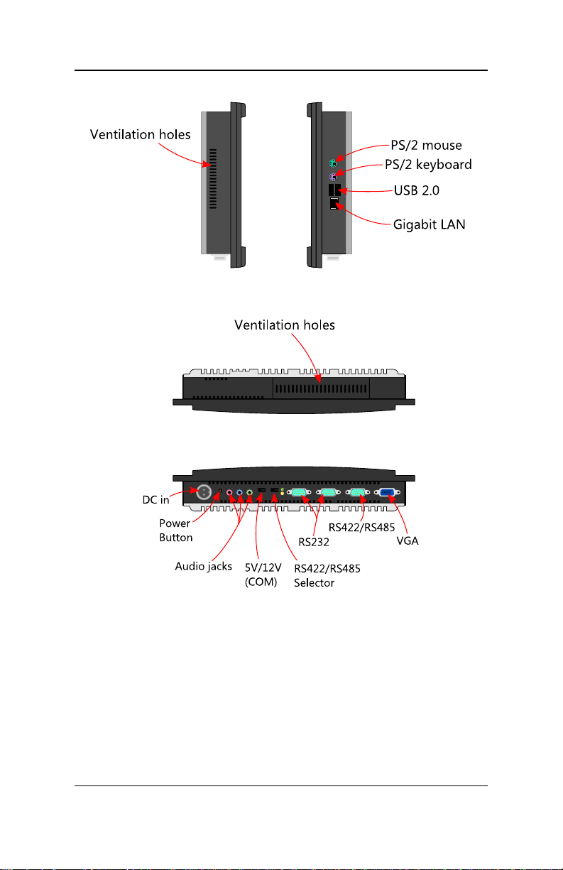
System I/O
Bottom I/O ports
• 1 x VGA connector
• 1 x RS-422/485 serial port (COM1)
• 2 x RS-232 serial ports (COM2 and COM4)
• 1 x 5V/12V selectable switch for COM2 and COM4
• 3 x Audio jacks consisting of Line-out, Line-in, and Mic-in
• 1 x ATX power button
• 1 x 2-pole, DC DIN jack power input connector
• 1 x antenna hole for the optional WLAN
Side I/O ports
• 1 x PS/2 mouse connector
• 1 x PS/2 keyboard connector
• 2 x USB 2.0 connectors
• 1 x RJ45 connector
Note:
Refer to Appendix A for the pin assignments of the system I/O ports.
5
Page 12

VIPRO VP7710 User’s Manual
Power Supply
Sub-Model VP7710-R1E16A1 VP7710-R1C10A1
Power Consumption
Input Voltage
Input Power Protection
Maximum 32w
Typical 24.6W
7VDC ~ 30V
Typical
7VDC @ 4.57A
12VDC @ 2.66A
16VDC @ 1.93A
19VDC @ 1.68A
24VDC @ 1.33A
30VDC @ 1.1A
Support Over Voltage protection
Support Over Current Protection
Support Under Voltage Protection
DC
Maximum 28w
Typical 22.8W
7VDC ~ 30V
Typical
7VDC @ 3.25A
12VDC @ 1.9A
16VDC @ 1.42A
19VDC @ 1.2A
24VDC @ 0.95A
30VDC @ 0.76A
DC
6
Page 13

VIPRO VP7710 User’s Manual
Environmental Specification
Operating Temperature
• 0°C ~ 45 °C
Storage Temperature
• -20°C ~ 70 °C
Relative Humidity
• 0 ~ 90% @ 45°C, non-condensing
Vibration Loading during operation
• When the system is only equipped with a Compact Flash Disk:
5 Grms, IEC 60068-2-64, random, 5 ~ 500 Hz, 1 Oct./min, 1
hr/axis
Shock during operation
• When system equipped with 2.5-inch Hard Disk Drive:
20 G, IEC 60068-2-27, half size, 11 ms duration
• When system equipped with Compact Flash Disk:
50 G, IEC 60068-2-27, half size, 11 ms duration
Front Panel Protection
• IP 65 compliant
EMC Approved
• CE/FCC Class B
Safety Approved
• UL/CB
7
Page 14
VIPRO VP7710 User’s Manual
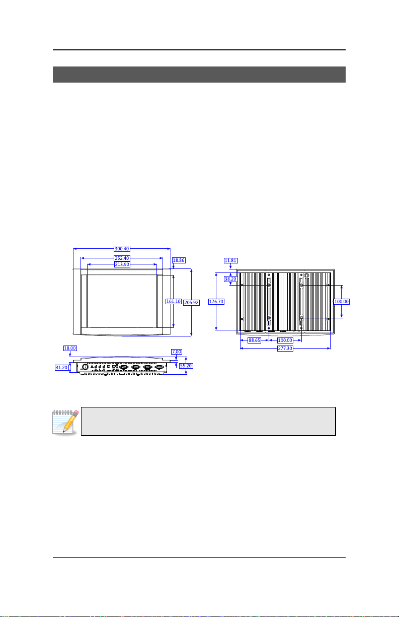
Unit: mm
Mechanical
Construction
• Aluminum mixed with heavy-duty steel
Mounting
• Panel/Wall/Table/VESA mountable
Weight
• 3.6 kg (7.9 lbs)
Dimensions (W x H x D)
• 300.4 mm x 205.9 mm x 55.2 mm (11.82” x 8.1” x 2.17”)
• VESA MIS-D 100 mounting interface (100 mm x 100 mm)
Note:
Specifications are subject to change without prior notice.
8
Page 15
VIPRO VP7710 User’s Manual
Layout
9
Page 16
VIPRO VP7710 User’s Manual
10
Page 17
VIPRO VP7710 User’s Manual
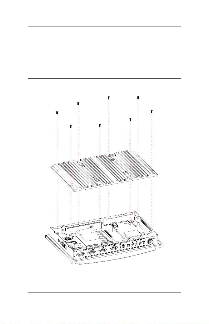
Removing the back plate
Remove the screws and lift off the back plate.
Installation
11
Page 18
VIPRO VP7710 User’s Manual
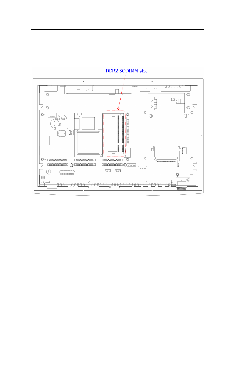
Installing Memory
Step 1
Locate the memory slot.
12
Page 19
VIPRO VP7710 User’s Manual
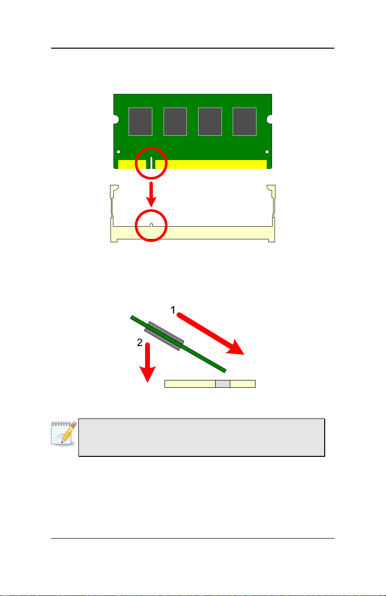
Step 2
Align the notch on the SODIMM with the memory slot.
Step 3
Insert the SODIMM at a 45 degree angle. Then push the SODIMM down
until it snaps into the locking mechanism.
Note:
Due to certain hardware limitations, DDR2 SDRAM modules
organized as 8 banks of 128 MB are not supported.
13
Page 20
VIPRO VP7710 User’s Manual
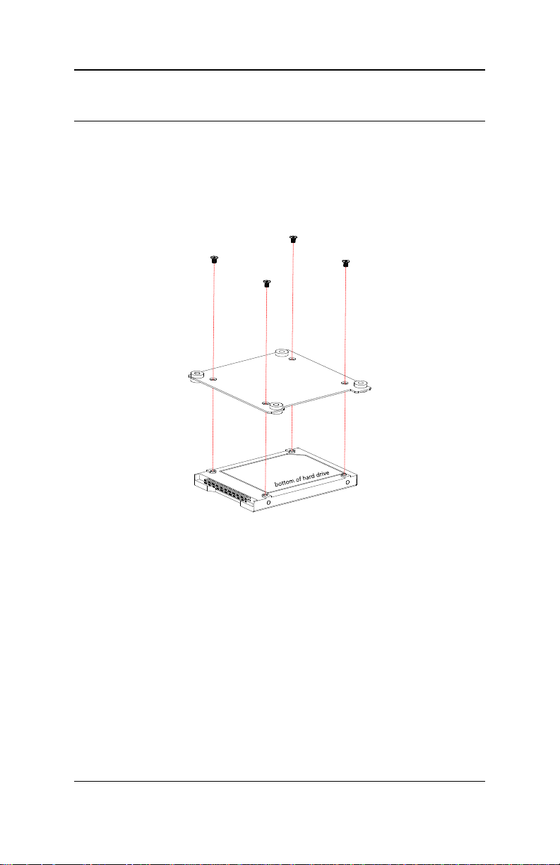
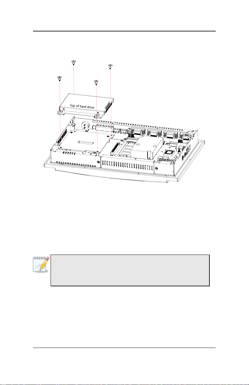
Installing the Hard Drive
Step 1
Remove the four flat screws and the hard drive mounting plate.
Step 2
Attach the 2.5 inch hard disk to the hard drive mounting plate.
14
Page 21
VIPRO VP7710 User’s Manual
Step 3
Align the hard drive mounting plate over the guard plate and fasten the
four flat screws to secure the hard drive.
Step 4
Attach one end of the hard disk data cable to the hard disk. Attach the
other end to the hard disk connector on the mainboard. The VIPRO
VP7710 supports both IDE and SATA hard drives. Depending on the
hard drive, use either the IDE or SATA cable and connect to the
appropriate port.
Note:
Modules in the VIPRO VP7710 Series are very fragile and sensitive.
Should you replace or return any component for repair, consult an
authorized technician to dismantle it.
15
Page 22
VIPRO VP7710 User’s Manual
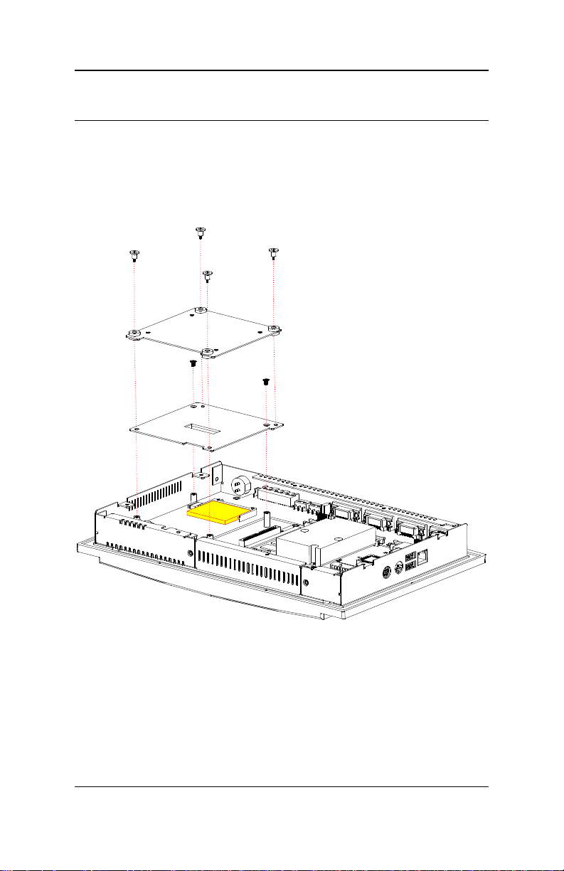
Installing the CF Memory
Step 1
Remove the four flat screws and the hard drive mounting plate.
Step 2
Remove the guard plate.
Step 3
Align the CF card with the side rails on the CF slot and insert firmly.
Step 4
Align the guard plate and insert the two flathead screws to the left and
right of the CF card.
16
Page 23

VIPRO VP7710 User’s Manual
Step 4
Align the hard drive mounting plate and secure it with the four flat
screws.
17
Page 24
VIPRO VP7710 User’s Manual
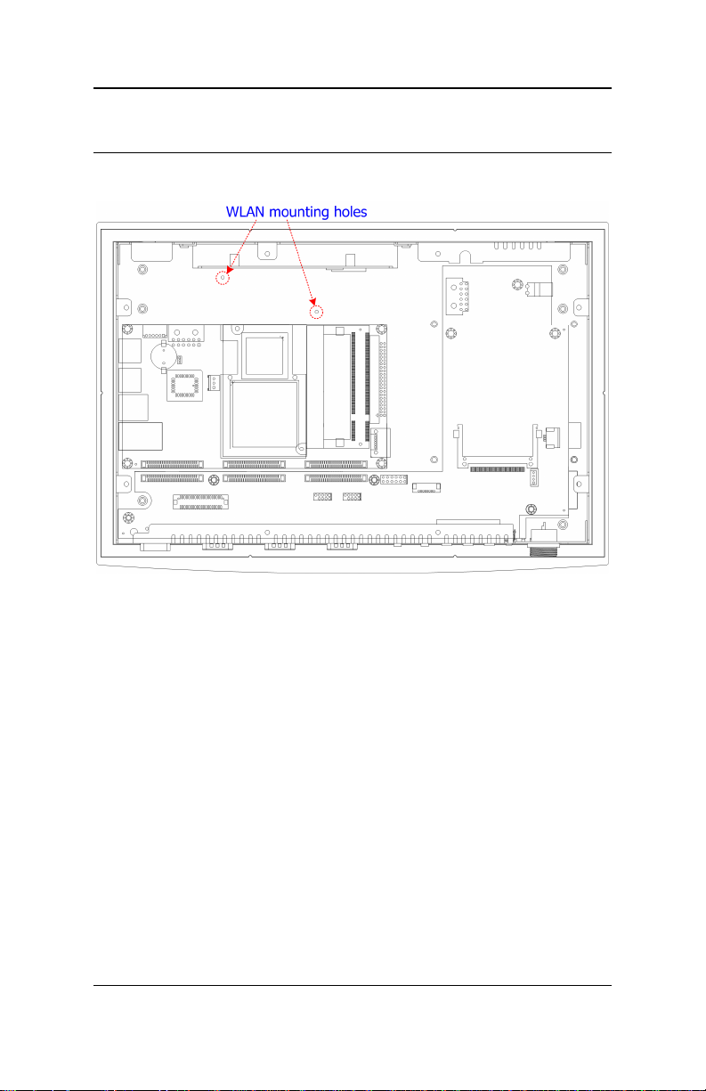
Installing the WLAN Module (optional)
Step 1
Locate the WLAN mounting holes.
18
Page 25

VIPRO VP7710 User’s Manual
Step 2
Align the WLAN module over the mounting hole and secure it with two
screws as shown.
Step 3
Attach the antenna cable to the WLAN module.
Step 4
Attach one end of the USB cable to the IO board and the other end to
the WLAN module.
Caution:
Before closing the VIPRO VP7710, ensure that the FFC cables
connecting the mainboard to the IO board are fully attached.
Otherwise, the VIPRO VP7710 may not function.
19
Page 26

VIPRO VP7710 User’s Manual
Step 5
After reattaching the backplate to the VIPRO VP7710, located the WLAN
antenna port. Screw on the WLAN antenna.
20
Page 27

VIPRO VP7710 User’s Manual
Mounting Options
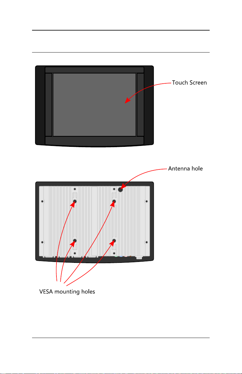
VESA Mounting Holes
The VIPRO VP7710 has VESA MIS-D 100 mounting holes on the back
plate. The mounting holes are set 10 cm apart (see the figure below).
The VIPRO VP7710 can only be mounted on VESA MIS-D 100
compatible devices.
21
Page 28

VIPRO VP7710 User’s Manual
Desktop Stand (optional)
An optional stand is available for enabling the VIPRO VP7710 to be
rested on a flat surface. For details on the assembly of the desktop stand,
refer to the installation guide provided with the desktop stand.
22
Page 29

VIPRO VP7710 User’s Manual
Unit: mm
Panel Mounting Kit
Panel mounting should be used in situations where only the front and
bezel of the VIPRO VP7710 will be visible. In order to complete a panel
mount, the wall must have a designated space (cutout) for embedding
the VIPRO VP7710.
A recommended cutout dimension is shown below.
Note:
The cutout shown above is for embedding the VIPRO VP7710
directly into the wall without an additional chassis. If using a chassis
to mount the VIPRO VP7710, ensure the cutout is sufficient for the
chassis.
23
Page 30

VIPRO VP7710 User’s Manual
Once the cutout has been prepared, slide the VIPRO VP7710 backwards
into the panel opening. From the other side of the panel, align the panel
mounting bracket on the rear of VIPRO VP7710 and attach the eight
screws through the mounting bracket into the backplate.
24
Page 31

VIPRO VP7710 User’s Manual
Then, secure the VIPRO VP7710 to the panel with four screws.
25
Page 32

VIPRO VP7710 User’s Manual
Wall Mounting Kit (optional)
Wall mounting should be used when the VIPRO VP7710 cannot be
embedded into the wall. When wall mounting, the entire system will be
exposed. For details on the assembly of the wall mounting kit, refer to
the installation guide provided with the wall mounting kit.
26
Page 33

VIPRO VP7710 User’s Manual
VIPRO VP7710 BIOS SETUP
Main Menu
Standard CMOS Features
Use this menu to set basic system configurations.
Advanced BIOS Features
Use this menu to set the advanced features available on your system.
Advanced Chipset Features
Use this menu to set chipset specific features and optimize system
performance.
Integrated Peripherals
Use this menu to set onboard peripherals features.
Power Management Setup
Use this menu to set onboard power management functions.
PnP/PCI Configurations
Use this menu to set the PnP and PCI configurations.
27
Page 34

VIPRO VP7710 User’s Manual
PC Health Status
This menu shows the PC health status.
Frequency/Voltage Control
Use this menu to set the system frequency and voltage control.
BIOS Setup
Load Optimized Defaults
Use this menu option to load BIOS default settings for optimal and high
performance system operations.
Set Supervisor Password
Use this menu option to set the BIOS supervisor password.
Set User Password
Use this menu option to set the BIOS user password.
Save & Exit Setup
Save BIOS setting changes and exit setup.
Exit Without Saving
Discard all BIOS setting changes and exit setup.
28
Page 35

VIPRO VP7710 User’s Manual
Standard CMOS Features
Date
The date format is [Day, Month Date Year]
Time
The time format is [Hour : Minute : Second]
Video
Settings: [EGA/VGA, CGA 40, CGA 80, Mono]
Halt On
Sets the system’s response to specific boot errors. Below is a table that
details the possible settings.
Setting Description
All Errors System halts when any error is detected
No Errors System does not halt for any error
All, But Keyboard System halts for all non-key errors
29
Page 36

VIPRO VP7710 User’s Manual
IDE Drives
The specifications of your drive must match with the drive table. The
hard disk will not work properly if you enter incorrect information in this
category.
Select “Auto” whenever possible. If you select “Manual”, make sure the
information is from your hard disk vendor or system manufacturer.
Below is a table that details required hard drive information when using
the “Manual” mode.
Setting Description
IDE Channel The name of this match the name of the menu.
Settings: [None, Auto, Manual]
Access Mode Settings: [CHS, LBA, Large, Auto]
Capacity Formatted size of the storage device
Cylinder Number of cylinders
Head Number of heads
Precomp Write precompensation
Landing Zone location of the landing zone
Sector Number of sectors
30
Page 37

VIPRO VP7710 User’s Manual
Advanced BIOS Features
Virus Warning
This item is used to enable or disable the VIRUS warning feature for IDE
Hard Disk boot sector protection.
Setting Description
Enabled Turns on hard disk boot sector virus protection
Disabled Turns off hard disk boot sector virus protection
Quick Power On Self-Test
Shortens Power On Self-Test (POST) cycle to enable shorter boot up
time.
Setting Description
Enabled Shorten Power On Self Test (POST) cycle and bootup
time
Disabled Standard Power On Self Test (POST)
31
Page 38

VIPRO VP7710 User’s Manual
First/Second/Third Boot Device
Set the boot device sequence as BIOS attempts to load the disk
operating system.
Setting Description
LS120 Boot from LS-120 drive
Hard Disk Boot from the HDD
CD-ROM Boot from CD-ROM
ZIP100 Boot from ATAPI ZIP drive
USB-FDD Boot from USB floppy drive
USB-ZIP Boot from USB ZIP drive
USB-CDROM Boot from USB CDROM
Legacy LAN Boot from network drive
VIA Networking Boot from network drive
Disabled Disable the boot device sequence
Boot Other Device
Enables the system to boot from alternate devices if the system fails to
boot from the “First/Second/Third Boot Device” list.
Setting Description
Enabled Enable alternate boot device
Disabled No alternate boot device allowed
Boot Up NumLock Status
Set the NumLock status when the system is powered on.
Setting Description
On Forces keypad to behave as 10-key
Off Forces keypad to behave as arrow keys
Typematic Rate Setting
Enables “Typematic Rate” and “Typematic Delay” functions.
Settings: [Enabled, Disabled]
Typematic Rate (Chars/Sec)
This item sets the rate (characters/second) at which the system retrieves
a signal from a depressed key.
Settings: [6, 8, 10, 12, 15, 20, 24, 30]
Typematic Delay (Msec)
This item sets the delay between when the key was first pressed and
when the system begins to repeat the signal from the depressed key.
Settings: [250, 500, 750, 1000]
32
Page 39

VIPRO VP7710 User’s Manual
Security Option
Selects whether the password is required every time the System boots,
or only when you enter Setup.
Setting Description
Setup Password prompt appears only when end users try to
run BIOS Setup
System Password prompt appears every time when the
computer is powered on and when end users try to
run BIOS Setup
APIC Mode
Settings: [Disabled, Enabled]
MPS Version Control for OS
Settings: [1.1, 1.4]
OS Select For DRAM > 64MB
Select OS2 only if you are running OS/2 operating system with greater
than 64MB of RAM on the system.
Settings: [Non-OS2, OS2]
Video BIOS Shadow
Enabled copies Video BIOS to shadow RAM Improves performance.
Settings: [Enabled, Disabled]
Full Screen Logo Show
Settings: [Disabled, Enabled]
Small Logo(EPA) Show
Settings: [Disabled, Enabled]
Summary Screen Show
Settings: [Disabled, Enabled]
33
Page 40

VIPRO VP7710 User’s Manual
CPU Feature
Deplay Prior to Thermal
Settings: [4 Min, 8 Min, 16 Min, 32 Min]
Thermal Management
This item sets CPU’s thermal control rule to protect CPU from overheat.
Setting Description
Thermal Monitor 1 On-die throttling
TM2 Bus Ratio
This item sets the frequency (bus ratio) of the throttled performance
that will be initiated when the on die sensor goes from not hot to hot.
TM2 Bus VID
This item sets the voltage of the throttled performance that will be
initiated when the on die sensor goes from not hot to hot.
C7 CMPXCHGB
Settings: [Disabled, Enabled]
C7 NoExecute (NX)
Settings: [Disabled, Enabled]
34
Page 41

VIPRO VP7710 User’s Manual
Hard Disk Boot Priority
This is for setting the priority of the hard disk boot order when the
“Hard Disk” option is selected in the “[First/Second/Third] Boot Device”
menu item.
35
Page 42

VIPRO VP7710 User’s Manual
Advanced Chipset Features
Caution:
The Advanced Chipset Features menu is used for optimizing the
chipset functions. Do not change these settings unless you are
familiar with the chipset.
Memory Hole
Settings: [Disabled, 15M – 16M]
System BIOS Cacheable
Settings: [Disabled, Enabled]
Video RAM Cacheable
Settings: [Disabled, Enabled]
Init Display First
Settings: [PCI Slot, AGP]
Display Device Output 1 / 2
Select from a variety of supported display devices.
Settings: [Disabled, CRT, LCD, TV, DVI, CRT2]
Panel Type
Key in a HEX number.
Settings: [Min = 0000, Max = 00FF]
36
Page 43

VIPRO VP7710 User’s Manual
AGP & P2P Bridge Control
AGP Aperture Size
This setting controls how much memory space can be allocated to AGP
for video purposes. The aperture is a portion of the PCI memory address
range dedicated to graphics memory address space. Host cycles that hit
the aperture range are forwarded to the AGP without any translation.
Settings: [32MB, 64MB, 128MB, 256MB, 512MB, 1G]
AGP 3.0 Mode
This mainboard supports the AGP 4x interface. When the AGP 4x is used,
it can transfer video data at 1066MB/s. AGP 4x is backward compatible,
leave the default 4x mode on.
Settings: [8x, 4x]
AGP Driving Control
This item is used to signal driving current on AGP cards to auto or
manual.
Settings: [Auto, Manual]
AGP Driving Value
Key in a HEX number.
Settings: [Min = 0000, Max = 00FF]
37
Page 44

VIPRO VP7710 User’s Manual
AGP Fast Write
This item is used to enable or disable the caching of display data for the
video memory of the processor.
Settings: [Enabled, Disabled]
AGP Master 1 WS Write
Settings: [Enabled, Disabled]
AGP Master 1 WS Read
Settings: [Enabled, Disabled]
AGP 3.0 Calibration Cycle
Settings: [Enabled, Disabled]
VGA Share Memory Size
Settings: [Disabled, 32M, 64M, 128M]
Direct Frame Buffer
Settings: [Enabled, Disabled]
38
Page 45

VIPRO VP7710 User’s Manual
CPU & PCI Bus Control
PCI Master 0 WS Write
Settings: [Enabled, Disabled]
PCI Delay Transaction
Settings: [Enabled, Disabled]
DRDY_Timing
Settings: [Slowest, Default, Optimize]
39
Page 46

VIPRO VP7710 User’s Manual
TV Output Connector
The TV Output Connector sub-menu gives access to enable or disable
the output connector types listed onscreen.
40
Page 47

VIPRO VP7710 User’s Manual
Integrated Peripherals
RS422/485 and Onboard Serial Port
Sets the base I/O port address and IRQ for the onboard serial ports.
Selecting “Auto” allows the BIOS to automatically determine the correct
base I/O port address.
Port Settings
RS422/485 Disabled 3F8
IRQ4
1 Disabled 3F8
IRQ4
2 Disabled 3F8
IRQ4
2F8
IRQ4
2F8
IRQ4
2F8
IRQ4
3E8
IRQ4
3E8
IRQ4
3E8
IRQ4
2E8
IRQ4
2E8
IRQ4
2E8
IRQ4
Auto
Auto
Auto
WatchDog Support
Settings: [Enabled, Disabled]
WatchDog Timer Select
This item can only be accessed if WatchDog Support is enabled.
Settings: [Second, Minute]
WatchDog Count Value
This item can only be accessed if WatchDog Support is enabled.
Key in a HEX number.
Settings: [Min = 0000, Max = 00FF]
41
Page 48

VIPRO VP7710 User’s Manual
VIA OnChip PCI Device
Azalia HDA Controller
Setting Description
Auto Enables onboard controller if audio device is
detected
Disabled Turn off onboard controller to allow external
controller
OnBoard LAN Boot ROM
Settings: [Enabled, Disabled]
42
Page 49

VIPRO VP7710 User’s Manual
USB Device Setting
USB 1.0 Controller
Enable or disable Universal Host Controller Interface for Universal Serial
Bus.
Settings: [Enabled, Disabled]
USB 2.0 Controller
Enable or disable Enhanced Host Controller Interface for Universal Serial
Bus.
Settings: [Enabled, Disabled]
USB Operation Mode
Auto decide USB device operation mode.
Setting Description
High Speed If USB device was high speed device, then it operated on
high speed mode. If USB device was full/low speed
device, then it operated on full/low speed mode.
Full/Low Speed All of USB Device operated on full/low speed mode
43
Page 50

VIPRO VP7710 User’s Manual
USB Keyboard Function
Enable or disable Legacy support of USB Keyboard
Settings: [Enabled, Disabled]
USB Storage Function
Enable or disable Legacy support of USB Mass Storage
Settings: [Enabled, Disabled]
44
Page 51

VIPRO VP7710 User’s Manual
Power Management Setup
Note:
ACPI is a power management specification that makes hardware
status information available to the operating system. ACPI enables a
PC to turn its peripherals on and off for improved power
management. It also allows the PC to be turned on and off by
external devices, so that mouse or keyboard activity wakes up the
computer.
ACPI Suspend Type
Setting Description
S1(POS) S1/Power On Suspend (POS) is a low power state. In
this state, no system context (CPU or chipset) is lost
and hardware maintains all system contexts.
S3(STR) S3/Suspend To RAM (STR) is a power-down state. In
this state, power is supplied only to essential
components such as main memory and wakeup-
capable devices. The system context is saved to main
memory, and context is restored from the memory
when a "wakeup" event occurs.
S1 & S3 Depends on the OS to select S1 or S3.
45
Page 52

VIPRO VP7710 User’s Manual
Power Management Option
Settings: [User Defined, Min Saving, Max Saving]
HDD Power Down
Sets the length of time for a period of inactivity before powering down
the hard disk.
Settings: [Disabled, 1~15(minutes)]
Suspend Mode
Sets the length of time for a period of inactivity before entering suspend
mode.
Settings: [Disabled, 1~15(minutes)]
Video Off Option
Select whether or not to turn off the screen when system enters power
saving mode, ACPI OS such as Windows XP will override this option.
Setting Description
Always On Screen is always on even when system enters power
saving mode
Suspend -> Off Screen is turned off when system enters power
saving mode
Video Off Method
Settings: [Blank Screen, V/H Sync+Blank, DPMS Support]
Modem Use IRQ
Settings: [NA, 3, 4, 5, 7, 9, 11]
Soft-off by PWRBTN
This field configures the power button on the chassis.
Setting Description
Delay 4 Sec System is turned off if power button is pressed for
more than four seconds
Instant-Off Power button functions as a normal power-on/-off
button
46
Page 53

VIPRO VP7710 User’s Manual
Run VGABIOS if S3 Resume
Settings: [Auto, Yes, No]
AC Loss Auto ReStart
The field defines how the system will respond after an AC power loss
during system operation.
Setting Description
Off Keeps the system in an off state until the power
button is pressed
On Restarts the system when the power is back
Former-Sts Former-Sts
47
Page 54

VIPRO VP7710 User’s Manual
Wakeup Event Detect
PS2KB Wakeup Select
When selecting “Password”, press <Page Up> or <Page Down> to
change password. The maximum number of characters is eight. “PS2MS
Wakeup from S3/S4/S5” and “PS2KB Wakeup from S3/S4/S5” will be
disabled while changing the password.
Settings: [Hot Key, Password]
PS2KB Wakeup Key Select
Sets a Hot Key to restore the system from the power saving mode to an
active state.
Settings: [Disabled, Ctrl+F1, Ctrl+F2, Ctrl+F3, Ctrl+F4, Ctrl+F5, Ctrl+F6,
Ctrl+F7, Ctrl+F8, Ctrl+F9, Ctrl+F10, Ctrl+F11, Ctrl+F12, Power, Wake, Any
Key]
PS2MS Wakeup Key Select
Enables any mouse activity to restore the system from the power saving
mode to an active state.
Settings: [Disabled, Enabled]
PS2 Keyboard Power On
Settings: [Disabled, Enabled]
PS2 Mouse Power On
Settings: [Disabled, Enabled]
48
Page 55

VIPRO VP7710 User’s Manual
USB Resume
Settings: [Disabled, Enabled]
PowerOn by PCI Card
Settings: [By OS, Enabled]
Wake Up On LAN/Ring
Enables any LAN or Ring-In signals from the LAN or modem to restore
the system from a suspended state to an active state.
Settings: [By OS, Enabled]
RTC Alarm Resume
Sets a scheduled time and/or date to automatically power on the system.
Settings: [Disabled, Enabled]
Date (of Month)
The field specifies the date for “RTC Alarm Resume”.
Resume Time (hh:mm:ss)
The field specifies the time for “RTC Alarm Resume”.
49
Page 56

VIPRO VP7710 User’s Manual
PnP/PCI Configurations
Note:
This section covers some very technical items and it is strongly
recommended to leave the default settings as is unless you are an
experienced user.
PNP OS Installed
Setting Description
Yes BIOS will only initialize the PnP cards used for
booting (VGA, IDE, SCSI). The rest of the cards will be
initialized by the PnP operating system
No BIOS will initialize all the PnP cards
Reset Configuration Data
This field should usually be left “Disabled”.
Setting Description
Enabled Resets the ESCD (Extended System Configuration
Data) after exiting BIOS Setup if a newly installed PCI
card or the system configuration prevents the
operating system from loading
Disabled Default setting
50
Page 57

VIPRO VP7710 User’s Manual
BIOS will automatically assign IRQ, DMA and memory
Resource Controlled By
Enables the BIOS to automatically configure all the Plug-and-Play
compatible devices.
Setting Description
Auto(ESCD)
base address fields
Manual Unlocks “IRQ Resources” for manual configuration
PCI/VGA Palette Snoop
Some non-standard VGA display cards may not show colors properly.
This field allows you to set whether MPEG ISA/VESA VGA Cards can
work with PCI/VGA or not. When enabled, a PCI/VGA can work with a
MPEG ISA/VESA VGA card. When disabled, a PCI/VGA cannot work with
a MPEG ISA/VESA Card.
Settings: [Disabled, Enabled]
Assign IRQ For VGA/USB
Assign IRQ for VGA and USB devices.
Settings: [Disabled, Enabled]
Maximum ASPM supported
Settings: [L0, L0s, L1, L0s&L1]
Maximum Payload Size
Settings: [128, 256, 512, 1024, 2048, 4096]
51
Page 58

VIPRO VP7710 User’s Manual
IRQ Resources
Note:
The items are adjustable only when “Resources Controlled By” is set
to “Manual.”
IRQ Resources list IRQ 3/5/7/9/10/11/14/15 for users to set each IRQ a
type depending on the type of device using the IRQ.
Setting Description
PCI Device For Plug-and-Play compatible devices designed for
PCI bus architecture
Reserved The IRQ will be reserved for other requests
52
Page 59

VIPRO VP7710 User’s Manual
PC Health Status
This screen displays real-time values for the voltages listed. In addition,
it shows the fan speed of any fan attached to the onboard fan connector.
53
Page 60

VIPRO VP7710 User’s Manual
Frequency / Voltage Control
Auto Detect PCI Clk
Settings: [Disabled, Enabled]
Spread Spectrum
When the mainboard's clock generator pulses, the extreme values
(spikes) of the pulses creates EMI (Electromagnetic Interference). The
Spread Spectrum function reduces the EMI generated by modulating
the pulses so that the spikes of the pulses are reduced to flatter curves.
Settings: [Disabled, 0.20%, 0.25%, 0.35%]
54
Page 61

VIPRO VP7710 User’s Manual
DRAM Clock/Drive Control
DRAM Clock
The chipset supports synchronous and asynchronous mode between
host clock and DRAM clock frequency.
Settings: [200MHz, 266MHz, 333MHz, By SPD]
DRAM Timing
The value in this field depends on the memory modules installed in your
system. Changing the value from the factory setting is not
recommended unless you install new memory that has a different
performance rating than the original modules.
Settings: [Manual, Auto By SPD]
SDRAM CAS Latency [DDR/DDR2]
This item is for setting the speed it takes for the memory module to
complete a command. Generally, a lower setting will improve the
performance of your system. However, if your system becomes less
stable, you should change it to a higher setting. This field is only
available when “DRAM Timing” is set to “Manual”.
Settings: [1.5/2, 2/3, 2.5/4, 3/5]
55
Page 62

VIPRO VP7710 User’s Manual
Bank Interleave
This item is for setting the interleave mode of the SDRAM interface.
Interleaving allows banks of SDRAM to alternate their refresh and access
cycles. One bank will undergo its refresh cycle while another is being
accessed. This improves performance of the SDRAM by masking the
refresh time of each bank. This field is only available when “DRAM
Timing” is set to “Manual”.
Settings: [Disabled, 2 Bank, 4 Bank, 8 Bank]
Precharge to Active (Trp)
This field is for setting the length of time it takes to precharge a row in
the memory module before the row becomes active. Longer values are
safer but may not offer the best performance. This field is only available
when “DRAM Timing” is set to “Manual”.
Settings: [2T, 3T, 4T, 5T]
Active to Precharge (Tras)
This field is for setting the length of time it a row stays active before
precharging. Longer values are safer but may not offer the best
performance.
This field is only available when “DRAM Timing” is set to “Manual”.
Settings: [05~20T]
Active to CMD (Trcd)
This field is only available when “DRAM Timing” is set to “Manual”.
Settings: [2T, 3T, 4T, 5T]
REF to ACT / REF (Trfc)
This field is only available when “DRAM Timing” is set to “Manual”.
Settings: [08~71T]
ACT(0) to ACT(1) (TRRD)
This field is only available when “DRAM Timing” is set to “Manual”.
Settings: [2T, 3T, 4T, 5T]
Read to Precharge (Trptp)
Settings: [2T, 3T]
Write to Read CMD (Twtr)
Settings: [1T/2T, 2T/3T]
56
Page 63

VIPRO VP7710 User’s Manual
Write Recovery Time (Twr)
Settings: [2T, 3T, 4T, 5T]
RDSAIT Mode
Settings: [Manual, Auto]
RDSAIT Selection
Key in a HEX number.
Settings: [Min = 0000, Max = 003F]
57
Page 64

VIPRO VP7710 User’s Manual
Load Optimized Defaults
This option is for restoring all the default optimized BIOS settings. The
default optimized values are set by the mainboard manufacturer to
provide a stable system with optimized performance.
Entering “Y” loads the default optimized BIOS values.
58
Page 65

VIPRO VP7710 User’s Manual
Set Supervisor / User Password
This option is for setting a password for entering BIOS Setup. When a
password has been set, a password prompt will be displayed whenever
BIOS Setup is run. This prevents an unauthorized person from changing
any part of your system configuration.
There are two types of passwords you can set. A supervisor password
and a user password. When a supervisor password is used, the BIOS
Setup program can be accessed and the BIOS settings can be changed.
When a user password is used, the BIOS Setup program can be accessed
but the BIOS settings cannot be changed.
To set the password, type the password (up to eight characters in length)
and press <Enter>. The password typed now will clear any previously set
password from CMOS memory. The new password will need to be
reentered to be confirmed. To cancel the process press <Esc>.
To disable the password, press <Enter> when prompted to enter a new
password. A message will show up to confirm disabling the password.
To cancel the process press <Esc>.
Additionally, when a password is enabled, the BIOS can be set to
request the password each time the system is booted. This would
prevent unauthorized use of the system. See “Security Option” in the
“Advanced BIOS Features” section for more details.
59
Page 66

VIPRO VP7710 User’s Manual
Save & Exit Setup
Entering “Y” saves any changes made and exits the program.
Entering “N” will cancel the exit request.
60
Page 67

VIPRO VP7710 User’s Manual
Exit Without Saving
Entering “Y” discards any changes made and exits the program.
Entering “N” will cancel the exit request
61
Page 68

VIPRO VP7710 User’s Manual
Appendix A
The pin assignments of the external system I/O ports on the bottom and
side of the system are described here.
62
Page 69

VIPRO VP7710 User’s Manual
Introduction of VIPRO VP7710 External I/O
Connectors
The following two figures show the external I/O connectors on VIPRO
VP7710. The following sections give you detailed information about the
function of each I/O connector.
Figure A.1: Bottom System I/O connectors
Figure A.2: Side System I/O connectors
63
Page 70

VIPRO VP7710 User’s Manual
VIPRO VP7710 Bottom System External I/O
Connectors
Power Input Connector
The VIPRO VP7710 comes with a 2-pole DIN-jack that carries external
power input of 7~30 VDC. Please refer to Figure A.3 and Table A.2.1 for
their pin assignments.
Pin 1
Pin 2
Figure A.3: 2-pole, DC DIN-Jack of Power Input connector
Table A.1: Power connector pin assignments
Pin Signal Name
1 +7 ~ 30VDC input voltage
2 GND
Power ON/OFF Switch Button
The VIPRO VP7710 comes with a Power On/Off button, that Support
dual function of Soft Power -On/Off (Instant off or Delay 4 Second), and
Suspend.
64
Page 71

VIPRO VP7710 User’s Manual
Audio Connector
The VIPRO VP7710 offers High Definition Audio output ports by three
phone jack (3.5φ, 5P, 90D(F)) connectors of Mic_In (Pink color), Line_In
(BLUE color), and Line_Out (GREEN color)
Table A.2: Mic_In connector
Mic-In Connector
Footprint Phone Jack 3.5Ø 5P, 90 Degree, Female, PINK color, with SHIELDED
Table A.3: Line_In connector
Line-In Connector
Footprint Phone Jack 3.5Ø 5P, 90 Degree, Female, BLUE color, with SHIELDED
Table A.4: Line_Out connector
Line-Out Connector
Footprint Phone Jack 3.5Ø 5P, 90 Degree, Female, GREEN color, with SHIELDED
5V/12V switch for COM 2 and COM4
The VIPRO VP7710 comes with a switch that can be configured to carry
the power source of either 5V or 12V for COM 2 and COM4.
RS-422/485 switch for COM1
The COM1 port connector can be configured to operate in either RS-422
or RS-485 mode by setting up this RS-422/485 switch.
LED indicators
There are two LEDs on bottom system I/O line of the VIPRO VP7710 for
indicating system status: PWR LED is for power status and Flash in
Orange color; and HDD LED is for hard disk and compact flash disk
status, which flash in Blue color.
65
Page 72

VIPRO VP7710 User’s Manual
COM2 and COM4 Connector
The VIPRO VP7710 provides two RS-232 ports by two D-sub 9-pin
connectors as COM2 and COM4. Please refer to Figure A.4 and Table A.5
for their pin assignments.
1 5
32 4
7 8
9
6
Figure A.4: COM 2 and COM 4 Connector
Table A.5: COM2 and COM4 standard serial port pin assignments
Pin Signal Name
1 DCD
2 RxD
3 TxD
4 DTR
5 GND
6 DSR
7 RTS
8 CTS
9 RI
66
Page 73

VIPRO VP7710 User’s Manual
COM1 Connector
The VIPRO VP7710 provides a RS-422/485 port, which can be configured
to operate in either RS-422 or RS-485 mode by setting up this RS422/485 switch. Please refer to Figure A.5 and Table A.6 for their pin
assignments.
1 5
32 4
7 8
9
6
Figure A.5: COM1 Connector
Table A.6: COM1 standard serial port pin assignments
Pin RS-422 Signal Name RS-485 Signal Name
1 Tx- Tx2 Tx+ Tx+
3 Rx+ NC
4 Rx- NC
5 GND GND
6 NC NC
7 NC NC
8 NC NC
9 NC NC
Note:
NC represents “No Connection”.
67
Page 74

VIPRO VP7710 User’s Manual
VGA Connector
The VIPRO VP7710 provides a high resolution VGA interface by a D-sub
15-pin connector to support the connection with a VGA CRT monitor
externally. Please refer to Figure A.6 and Table 2.7 for their pin
assignments.
5
10 6
15
11
1
Figure A.6: VGA connector
Table A.7: VGA port pin assignments
Pin Signal Name Pin Signal Name
1 RED 9 NC
2 GREEN 10 GND
3 BLUE 11 NC
4 NC 12 DDC DATA
5 GND 13 H-SYNC
6 GND 14 V-SYNC
7 GND 15 DDC CLOCK
8 GND
68
Page 75

VIPRO VP7710 User’s Manual
VIPRO VP7710 Side System External I/O
connectors
PS/2 Keyboard and PS/2 Mouse Connector
The VIPRO VP7710 provides a PS/2 keyboard connector and a PS/2
mouse connector. Two 6-pin mini-DIN connectors are located on the
right side of the VIPRO VP7710. Please refer to Figure A.7 and Table A.8
for its pin assignments.
6
5
4
3
12
Figure A.7: PS/2 Mouse and PS/2 Keyboard connector
Table A.8: PS2 Connectors
Pin Keyboard Signals Pin Mouse Signals
1 KB DATA 9 MS DATA
2 NC 10 NC
3 GND 11 GND
4 +5V 12 +5V
5 KB CLOCK 13 MS CLOCK
NC NC
69
Page 76

VIPRO VP7710 User’s Manual
USB Connectors
The VIPRO VP7710 provides two USB-interface connectors located on
right side of it. These USB-interface connectors give complete Plug &
Play and hot swapping for up to 127 external devices. The USB interface
can be disabled in the system BIOS setup. Please refer to Figure A.8 and
Table A.9 for its pin assignments.
The USB-interface connector is used for connecting any device that
conforms to the USB interface. Many recent digital devices conform to
this standard. The USB interface supports Plug and Play, which enables
you to connect or disconnect a device whenever you want, without
turning off the computer.
Figure A.8: USB connector
Table A.9 USB Connector
Pin Signal Name
1 VCC
2 USB_P03 USB_P0+
4 GND
70
Page 77

VIPRO VP7710 User’s Manual
Ethernet Connector (LAN)
The VIPRO VP7710 is equipped with a VIA VT6122 Gigabit Ethernet
controller that is fully compliant with IEEE 802.3 (10BASE-T), 802.3u
(100BASE-TX), and 802.3ab (1000BASE-T) standards.
1 81 8
Figure 2.6: RJ-45 Connector
Table A.10: RJ-45 Connector pin assignments
Pin Signal Name
1 Tx+
2 Tx3 Rx+
4 Rx5 TxA+
6 TxA7 RxA+
8 RxA-
The Ethernet port provides a standard RJ-45 jack connector with LED
indicators on the front side to show its Active/Link status, please find the
details from table A.11 below.
Table A.11: LAN LED status indicators
Speed Active Link
10 Base-T Orange Blink N/A
100 Base-T Orange Blink Red
1000 Base-T Orange Blink Green
71
 Loading...