

Page 1
Page 2

USER MANUAL
Video Wall Mini
Fanless and Slim size system with
4-display HDMI support
1.03-10312014-140100
Page 3

Copyright
Copyright © 2014 VIA Technologies Incorporated. All rights reserved.
No part of this document may be reproduced, transmitted, transcribed, stored in a retrieval system, or translated into any language,
in any form or by any means, electronic, mechanical, magnetic, optical, chemical, manual or otherwise without the prior written
permission of VIA Technologies, Incorporated.
Trademarks
All trademarks are the property of their respective holders.
Disclaimer
No license is granted, implied or otherwise, under any patent or patent rights of VIA Technologies. VIA Technologies makes no
warranties, implied or otherwise, in regard to this document and to the products described in this document. The information
provided in this document is believed to be accurate and reliable as of the publication date of this document. However, VIA
Technologies assumes no responsibility for the use or misuse of the information (including use or connection of extra
device/equipment/add-on card) in this document and for any patent infringements that may arise from the use of this document.
The information and product specifications within this document are subject to change at any time, without notice and without
obligation to notify any person of such change.
VIA Technologies, Inc. reserves the right the make changes to the products described in this manual at any time without prior
notice.
Regulatory Compliance
FCC
FCC----A Radio Frequency
A Radio Frequency Interference Statement
FCCFCC
A Radio FrequencyA Radio Frequency
This equipment has been tested and found to comply with the limits for a class A digital device, pursuant to part 15 of the FCC
rules. These limits are designed to provide reasonable protection against harmful interference when the equipment is operated in a
commercial environment. This equipment generates, uses, and can radiate radio frequency energy and, if not installed and used in
accordance with the instruction manual, may cause harmful interference to radio communications. Operation of this equipment in a
residential area is likely to cause harmful interference, in which case the user will be required to correct the interference at his
personal expense.
Notice 1
Notice 1
Notice 1Notice 1
The changes or modifications not expressly approved by the party responsible for compliance could void the user's authority to
operate the equipment.
Notice 2
Notice 2
Notice 2Notice 2
Shielded interface cables and A.C. power cord, if any, must be used in order to comply with the emission limits.
Notice 3
Notice 3
Notice 3Notice 3
The product described in this document is designed for general use, VIA Technologies assumes no responsibility for the conflicts
or damages arising from incompatibility of the product. Check compatibility issue with your local sales representatives before
placing an order.
Interference Statement
Interference Statement Interference Statement
Tested To Comply
With FCC Standards
FOR HOME OR OFFICE USE
Page 4

Battery Recycling and Disposal
Only use the appropriate battery specified for this product.
Do not re-use, recharge, or reheat an old battery.
Do not attempt to force open the battery.
Do not discard used batteries with regular trash.
Discard used batteries according to local regulations.
Safety Precautions
Always read the safety instructions carefully.
Keep this User's Manual for future reference.
All cautions and warnings on the equipment should be noted.
Keep this equipment away from humidity.
Lay this equipment on a reliable flat surface before setting it up.
Make sure the voltage of the power source and adjust properly 110/220V before connecting
the equipment to the power inlet.
Place the power cord in such a way that people cannot step on it.
Always unplug the power cord before inserting any add-on card or module.
If any of the following situations arises, get the equipment checked by authorized service
personnel:
The power cord or plug is damaged.
Liquid has penetrated into the equipment.
The equipment has been exposed to moisture.
The equipment has not worked well or you cannot get it work according to User's Manual.
The equipment has dropped and damaged.
The equipment has obvious sign of breakage.
Do not leave this equipment in an environment unconditioned or in a storage temperature
above 60°C (140°F). The equipment may be damaged.
Do not leave this equipment in direct sunlight.
Never pour any liquid into the opening. Liquid can cause damage or electrical shock.
Do not place anything over the power cord.
Do not cover the ventilation holes. The openings on the enclosure protect the equipment
from overheating
Page 5

Video Wall Mini User Manual
Video Wall Mini User Manual
Video Wall Mini User ManualVideo Wall Mini User Manual
Box Contents
ATG
ATG----A1400
A1400----3Q10A1
ATGATG
A1400A1400
1 x Video Wall Mini system unit
1 x Power cord, 180 cm, Japan Type
1 x Power adaptor, 12V/8.5A 102W
1 x Power cable, 4-hole DC-In jack
2 x HDMI cable strap holder
4 x SATA SSD screws
4 x Mounting screws
2 x Screws for Mini card (module) installation
1 x 0.392cc thermal grease in tube syringe
VIA MagicView content management software (Multi-language/default English ver.)
3Q10A1
3Q10A13Q10A1
iv
Page 6

Video Wall Mini User Manual
Video Wall Mini User Manual
Video Wall Mini User ManualVideo Wall Mini User Manual
Ordering Information
Part Number
Part Number Description
Part NumberPart Number
ATG
ATG----A1400
A1400----3Q10A1
ATGATG
3Q10A1 Fanless Embedded System with 1.0+GHz VIA QuadCore
A1400A1400
3Q10A13Q10A1
Description
DescriptionDescription
processor, 4 x HDMI®, 2 x USB 2.0, 2 x USB 3.0, 1 x GigaLAN, 1 x
COM (RS-232), 1 x Digital I/O, HD Audio (Line-In and Line-Out) 1
x SATA SSD bay and DC-In 12V, power cord Japan type.
Optional Accessories
Peripherals
Peripherals
PeripheralsPeripherals
Model Number
Model Number Description
Model NumberModel Number
EMIO-1533-00A2 802.11 b/g/n Wireless LAN USB Module
EMIO-1541-00A1 HSPA/WCDMA/EDGE/GPRS mobile broadband Mini PCIe Card
External AC
External AC----to
External ACExternal AC
Model Number
Model Number Description
Model NumberModel Number
99G33-020316 AC-to-DC adaptor, 12V/8.5A 102W
99G33-02032C Power Cord, 180 cm, USA type
99G33-02033C Power Cord, 180 cm, Europe type
99G33-02034C Power Cord, 180 cm, Japan type
99G33-02103C Power Cord, 180 cm, China type
to----DC Adapter and
DC Adapter and Power C
toto
DC Adapter and DC Adapter and
Description
DescriptionDescription
Module
Power Cord
Power CPower C
Description
DescriptionDescription
ord
ordord
v
Page 7

Video Wall Mini User Manual
Video Wall Mini User Manual
Video Wall Mini User ManualVideo Wall Mini User Manual
Table of Contents
1.
1. Product Overview
Product Overview................................
1.1.
Product OverviewProduct Overview
1.1.
Key Features................................................................................................... 1
1.1.1. Powered by VIA® QuadCore Processor............................................... 1
1.1.2. Fanless and Rugged Chassis.................................................................... 1
1.1.3. Multiple Display Support...................................................................... 2
1.1.4. Optimize Integration with Multiple I/O Access .............................. 2
1.1.5. Storage Expansion .................................................................................. 2
1.1.6. Wide Range of Operating Temperatures........................................... 2
1.1.7. Shock Resistant ........................................................................................ 2
1.1.8. Networking Support............................................................................... 2
1.1.9. Embedded OS ready ............................................................................. 2
1.2.
Product Specifications................................................................................. 3
1.3.
Panel Layout .................................................................................................. 7
1.4.
Dimensions .................................................................................................... 9
2.
2. External I/O Pin Descriptions and Functionality
External I/O Pin Descriptions and Functionality................................
2.2.
External I/O Pin Descriptions and FunctionalityExternal I/O Pin Descriptions and Functionality
2.1.
Front Panel I/O............................................................................................ 11
2.1.1. DC-In Jack (Power Input) .................................................................... 11
2.1.2. Power Button ......................................................................................... 11
2.1.3. HDMI® Port............................................................................................. 12
2.1.4. LED Indicators (Power LED and SATA SSD LED).......................... 13
2.1.5. RJ-45 LAN Port (Gigabit Ethernet) .................................................... 14
2.1.6. Audio Jacks............................................................................................. 15
2.1.7. USB 3.0 Port ........................................................................................... 15
2.2.
Right Side Panel.......................................................................................... 16
2.2.1. LED Indicators (3G/3.5G and WLAN)................................................16
2.2.2. Digital I/O Connector ..........................................................................16
2.2.3. USB 2.0 Port ........................................................................................... 17
2.2.4. COM Connector.................................................................................... 18
................................................................
................................................................
................................................................
................................................................
.............................................
................................................................
................................ 1111
................................................................
............. 11
..........................
11
1111
3.
3. Onboard Connector and Pin Headers
Onboard Connector and Pin Headers................................
3.3.
Onboard Connector and Pin HeadersOnboard Connector and Pin Headers
3.1.
LPC Connector ............................................................................................19
3.2.
VGA Pin Header ......................................................................................... 20
3.3.
SPI Pin Header............................................................................................. 21
3.4.
System Temperature Sensor Pin Header............................................... 22
4.
4. Onboard Jumpers
Onboard Jumpers ................................
4.4.
Onboard JumpersOnboard Jumpers
4.1.
System Reset Jumper................................................................................. 24
................................................................
................................................................
.............................................................
................................................................
..............................................................
................................................................
............................. 19
..........................................................
.............................. 23
............................................................
19
1919
23
2323
vi
Page 8

Video Wall Mini User Manual
4.2.
Reset CMOS RAM Jumper........................................................................25
4.3.
SPI Address Select Jumper ...................................................................... 26
4.4.
Recovery BIOS Jumper.............................................................................. 27
4.5.
VDD/VSUSVDD Mode Select Jumper ................................................... 28
5.
5. Hardware Installation
Hardware Installation ................................
5.5.
Hardware InstallationHardware Installation
5.1.
How to remove the top cover ................................................................ 29
5.2.
How to reinstall the top cover ............................................................... 30
5.3.
How to install the DDR3 SODIMM memory ....................................... 32
5.4.
How to remove the DDR3 SODIMM memory..................................... 33
5.5.
How to install the 2.5-inch SATA SSD .................................................34
5.6.
How to install the mSATA module ....................................................... 36
5.7.
How to insert SIM card ............................................................................. 37
5.8.
How to install 3G/3.5G module and antenna..................................... 38
5.9.
How to install WLAN USB module and antenna ............................... 41
6.
6. BIOS Setup Ut
BIOS Setup Utility
6.6.
BIOS Setup UtBIOS Setup Ut
6.1.
Entering the BIOS Setup Utility............................................................... 45
6.2.
Control Keys................................................................................................ 45
6.3.
Getting Help................................................................................................45
6.4.
System Overview........................................................................................46
6.4.1. BIOS Information................................................................................... 46
6.4.2. Memory Information ............................................................................. 46
6.4.3. System Language................................................................................... 46
6.4.4. System Date............................................................................................47
6.4.5. System Time ........................................................................................... 47
6.5.
Advanced Settings ..................................................................................... 48
6.5.1. ACPI Settings.......................................................................................... 49
6.5.2. S5 RTC Wake Settings .......................................................................... 50
6.5.3. CPU Configuration ................................................................................51
6.5.4. SATA Configuration.............................................................................. 52
6.5.5. USB Configuration................................................................................. 53
6.5.6. F71869 Super IO Configuration ......................................................... 55
6.5.7. PC Health Status....................................................................................56
6.5.8. Clock Generator Configuration..........................................................57
6.6.
Chipset Settings ..........................................................................................58
6.6.1. DRAM Configuration ............................................................................59
6.6.2. Video Configuration ............................................................................. 61
6.6.3. PMU_ACPI Configuration .................................................................... 63
6.6.4. HDAC Configuration ............................................................................ 65
6.6.5. Others Configuration............................................................................66
ility ................................
ilityility
................................................................
................................................................
................................................................
................................................................
........................................................
................................................................
..............................................................
................................................................
Video Wall Mini User Manual
Video Wall Mini User ManualVideo Wall Mini User Manual
........................ 29
................................................
.............................. 45
............................................................
29
2929
45
4545
vii
Page 9

Video Wall Mini User Manual
6.7.
Boot Settings ............................................................................................... 68
6.7.1. Boot Configuration................................................................................68
6.7.2. Boot Option Priorities .......................................................................... 69
6.8.
Security Settings ......................................................................................... 70
6.8.1. Security Settings ....................................................................................70
6.9.
Save & Exit ................................................................................................... 71
6.9.1. Save Changes and Exit ......................................................................... 71
6.9.2. Discard Changes and Exit....................................................................71
6.9.3. Save Changes and Reset ...................................................................... 71
6.9.4. Discard Changes and Reset................................................................. 72
6.9.5. Save Changes ......................................................................................... 72
6.9.6. Discard Changes.................................................................................... 72
6.9.7. Save as User Defaults........................................................................... 72
6.9.8. Restore User Defaults .......................................................................... 72
6.9.9. Launch EFI Shell from file system device ........................................ 72
7.
7. Software and Technical Supports
Software and Technical Supports ................................
7.7.
Software and Technical SupportsSoftware and Technical Supports
7.1.
Microsoft Support ...................................................................................... 73
7.1.1. Driver Installation.................................................................................. 73
7.2.
Technical Supports and Assistance........................................................ 73
Appendix A. Quick Setup Diagram
Appendix A. Quick Setup Diagram................................
Appendix A. Quick Setup DiagramAppendix A. Quick Setup Diagram
................................................................
................................................................
................................................................
................................................................
Video Wall Mini User Manual
Video Wall Mini User ManualVideo Wall Mini User Manual
....................................
................................................................
...............................................
................................................................
.... 73
........
............... 75
..............................
73
7373
75
7575
viii
Page 10

Video Wall Mini User Manual
Video Wall Mini User Manual
Video Wall Mini User ManualVideo Wall Mini User Manual
Lists of Figures
Figure 1: Front side layout label .................................................................................... 7
Figure 2: Right side layout label .................................................................................... 7
Figure 3: Rear side layout label ..................................................................................... 7
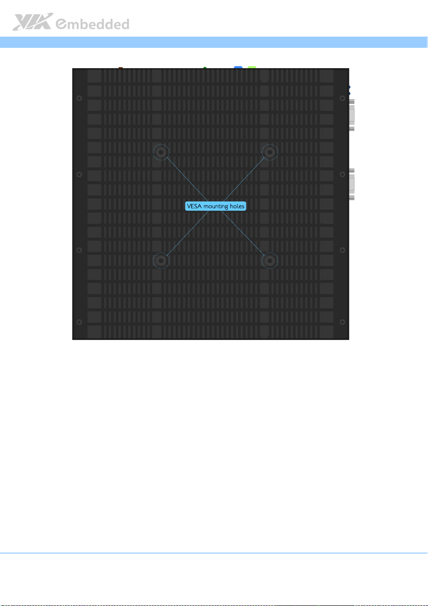
Figure 4: Bottom side layout label................................................................................ 8
Figure 5: Front view dimensions .................................................................................... 9
Figure 6: Side view dimensions ...................................................................................... 9
Figure 7: Bottom view dimensions .............................................................................. 10
Figure 8: DC-In jack diagram ......................................................................................... 11
Figure 9: Power button diagram .................................................................................. 11
Figure 10: HDMI® port diagram.................................................................................... 12
Figure 11: Power and SATA SSD LED indicator diagram....................................... 13
Figure 12: RJ-45 LAN port diagram .............................................................................14
Figure 13: Audio jack receptacle stack diagram....................................................... 15
Figure 14: USB 3.0 port diagram ..................................................................................15
Figure 15: 3G/3.5G and WLAN LED indicator .......................................................... 16
Figure 16: DIO connector diagram.............................................................................. 16
Figure 17: USB 2.0 port diagram ..................................................................................17
Figure 18: COM connector diagram ........................................................................... 18
Figure 19: LPC connector diagram............................................................................... 19
Figure 20: VGA pin header diagram............................................................................20
Figure 21: SPI pin header diagram ............................................................................... 21
Figure 22: System temperature sensor pin header diagram ..................................22
Figure 23: Jumper settings example............................................................................23
Figure 24: System reset jumper diagram .................................................................... 24
Figure 25: Reset CMOS RAM jumper diagram .......................................................... 25
Figure 26: SPI address select jumper diagram .......................................................... 26
Figure 27: Recovery BIOS jumper diagram ................................................................ 27
Figure 28: VDD/VSUSVDD mode select jumper diagram...................................... 28
Figure 29: Removing top cover .................................................................................... 29
Figure 30: Spreading thermal grease ..........................................................................30
Figure 31: Aligning the top cover................................................................................ 31
Figure 32: Securing the top cover ............................................................................... 31
Figure 33: Installing DDR3 SODIMM module ........................................................... 32
Figure 34: Disengaging the SODIMM locking clips ................................................. 33
Figure 35: Removing the memory module ................................................................ 33
Figure 36: Removing SATA SSD bay ........................................................................... 34
Figure 37: Installing hard drive bay to 2.5-inch SATA SSD ...................................34
Figure 38: Installing SATA SSD and connecting SATA cables .............................35
Figure 39: Inserting mSATA module ........................................................................... 36
ix
Page 11

Video Wall Mini User Manual
Figure 40: Securing mSATA module........................................................................... 36
Figure 41: Inserting 3G/3.5G SIM card ........................................................................ 37
Figure 42: Inserting 3G/3.5G module ......................................................................... 38
Figure 43: Securing 3G/3.5G module .........................................................................39
Figure 44: Installing 3G/3.5G antenna ........................................................................ 40
Figure 45: Installing WLAN USB module...................................................................41
Figure 46: Installing WLAN antenna ........................................................................... 42
Figure 47: Connecting WLAN board to board cable ............................................. 43
Figure 48: Illustration of the Main menu screen....................................................... 46
Figure 49: Illustration of the Advanced Settings screen......................................... 48
Figure 50: Illustration of the ACPI Settings screen .................................................. 49
Figure 51: Illustration of the S5 RTC Wake Settings screen................................... 50
Figure 52: Illustration of CPU Configuration screen................................................ 51
Figure 53: Illustration of SATA Configuration screen ............................................. 52
Figure 54: Illustration of USB Configuration .............................................................. 53
Figure 55: Illustration of F71869 Super IO Configuration screen.........................55
Figure 56: Illustration of PC Health Status screen ................................................... 56
Figure 57: Illustration of Clock Generator Configuration screen ......................... 57
Figure 58: Illustration of Chipset Settings screen..................................................... 58
Figure 59: Illustration of DRAM Configuration screen............................................ 59
Figure 60: Illustration of Video Configuration screen ............................................. 61
Figure 61: Illustration of PMU_ACPI Configuration screen.................................... 63
Figure 62: Illustration of Other Control screen........................................................ 64
Figure 63: Illustration of HDAC Configuration screen............................................ 65
Figure 64: Illustration of Others Configuration screen ........................................... 66
Figure 65: Illustration of Boot Settings screen.......................................................... 68
Figure 66: Illustration of Security Settings screen.................................................... 70
Figure 67: Illustration of Save & Exit screen.............................................................. 71
Figure 68: Front side setup diagram ............................................................................ 76
Figure 69: Rear side setup diagram .............................................................................77
Video Wall Mini User Manual
Video Wall Mini User ManualVideo Wall Mini User Manual
x
Page 12

Video Wall Mini User Manual
Video Wall Mini User Manual
Video Wall Mini User ManualVideo Wall Mini User Manual
Lists of Tables
Table 1: DC-In jack pinout ............................................................................................ 11
Table 2: HDMI® port pinout ......................................................................................... 12
Table 3: RJ-45 LAN port pinout................................................................................... 14
Table 4: RJ-45 LAN port color definition .................................................................. 14
Table 5: USB 3.0 port pinout........................................................................................ 15
Table 6: DIO connector pinout ................................................................................... 16
Table 7: USB 2.0 port pinout........................................................................................ 17
Table 8: COM connector pinout ................................................................................. 18
Table 9: LPC connector pinout .................................................................................... 19
Table 10: VGA pin header pinout ............................................................................... 20
Table 11: SPI pin header pinout .................................................................................. 21
Table 12: System temperature sensor pin header pinout......................................22
Table 13: System reset jumper settings .....................................................................24
Table 14: Reset CMOS RAM jumper settings ........................................................... 25
Table 15: SPI address select jumper settings ...........................................................26
Table 16: Recovery BIOS jumper settings .................................................................27
Table 17: VDD/VSUSVDD mode select jumper settings....................................... 28
xi
Page 13

Video Wall Mini User Manual
1.
1. Product Overview
Product Overview
1.1.
Product OverviewProduct Overview
The Video Wall Mini is a rugged and completely fanless embedded system
designed with 4-display (HDMI) support via discrete S3 5400E graphics
processor onboard. Its system is based on the EITX-2003 mainboard powered
by 1.0+ GHz VIA QuadCore processor which is superb in multi-tasking
performance, high power computing operation with lower power
consumption.
The Video Wall Mini system supports dual-sided multiple I/O connectors such
as high definition audio jacks, USB ports, Gigabit Ethernet LAN port,
configurable COM connector and DIO connector. The Video Wall Mini system
offers a 2.5” SATA SSD bay and an optional WLAN USB (WiFi) connectivity
which can be supported through one on-board USB pin header. In addition, it
supports mini PCIe card slots for mSATA storage and 3G/3.5G connectivity
with SIM card slot.
The Video Wall Mini’s system chassis is a robust aluminum (top and bottom
cover) alloy and it is designed to support VESA-mounting for quick installation
and easy maintenance.
These combined features make the Video Wall Mini perfect for various digital
signage, video-wall, gaming, industrial and embedded applications.
Video Wall Mini User Manual
Video Wall Mini User ManualVideo Wall Mini User Manual
1.1. Key Features
1.1.1. Powered by VIA
The Video Wall Mini system is powered by VIA® QuadCore 1.0+ GHz
processor. The VIA® QuadCore processor has combined four 64-bit “Isaiah”
cores on two dies offering enhanced multi-tasking and superb multimedia
performance on a low power budget.
1.1.2. Fanless and Rugged Chassis
The Video Wall Mini features fanless operation in a ruggedized aluminum
chassis that does double duty as a thermal solution and designed to ensure
maximum reliability.
1
®
QuadCore Processor
Page 14

Video Wall Mini User Manual
Video Wall Mini User Manual
Video Wall Mini User ManualVideo Wall Mini User Manual
1.1.3. Multiple Display Support
The Video Wall Mini system comes with discrete S3 5400E graphics processor
that gives the ability to support four HDMI displays. Each display has a
maximum high definition resolution of 1920 x 1080p.
1.1.4. Optimize Integration with Multiple I/O Access
Front and right side I/O access enables the Video Wall Mini system to easily
access to peripherals, support various applications, easy integration, quick
setup and easy maintenance.
1.1.5. Storage Expansion
In addition to 2.5-inch SATA SSD supports, the onboard mini PCIe card slot
enables the Video Wall Mini to have a flexible storage mSATA module.
1.1.6. Wide Range of Operating Temperatures
The Video Wall Mini carries a qualified thermal performance design which
allows a wide range of operating temperatures from 0°C ~ 45°C, suitable for
critical applications.
1.1.7. Shock Resistant
The Video Wall Mini is shock resistant to 50G for maximum reliability.
1.1.8. Networking Support
The Video Wall Mini is equipped with RJ-45 port that supports high speed
Gigabit Ethernet. It also has wireless networking option that gives the system a
freedom of WiFi (WLAN) access and 3G/3.5G network connectivity through
mini PCIe card slot and USB pin header respectively.
1.1.9. Embedded OS ready
The Video Wall Mini is 100% compatible with Microsoft Windows 7, Microsoft
Windows Embedded Standard 7 with MagicView
2
Page 15

Video Wall Mini User Manual
Video Wall Mini User Manual
Video Wall Mini User ManualVideo Wall Mini User Manual
1.2. Product Specifications
Processor
Processor Core Logic System
ProcessorProcessor
Graphics
Graphics
GraphicsGraphics
Gigabit Ethernet
Gigabit Ethernet
Gigabit EthernetGigabit Ethernet
High Definition Audio
High Definition Audio
High Definition AudioHigh Definition Audio
Core Logic System
Core Logic System Core Logic System
CPU
CPU
CPUCPU
VIA QuadCore U4650E 1.0+ GHz processor
800 MHz Front Side Bus
4 MB L2 Cache memory
Chipset
Chipset
ChipsetChipset
System Memory
System Memory
System MemorySystem Memory
BIOS
BIOS
BIOSBIOS
System Pow
System Power Management
System PowSystem Pow
Controller
Controller
ControllerController
NanoBGA2 package
VIA VX11H Media System Processor
33 mm x 33 mm FCBGA
One SODIMM slot supporting DDR3 1066/1333 MHz SDRAM
Supports up to 8 GB memory size
AMI BIOS
32 Mbit EFI SPI flash memory
er Management
er Managementer Management
Times Power On
ACPI 3.0 compliant
Integrated VIA Chrome™ 645/640 (DX11) graphics processor with 2D/3D video
acceleration with MPEG-2, VC-1 and H.264 video decoder
Display Memory
Display Memory
Display MemoryDisplay Memory
Optimized Shared Memory Architecture (UMA), supports 256MB to 1GB frame
buffer using system memory
HDMI
HDMI® Interface
Interface
HDMIHDMI
Interface Interface
Supports four onboard HDMI® ports via S3 5400E graphics
Video Wall
Video Wall
Video WallVideo Wall
Four onboard HDMI ports via S3 5400E graphics can support four display video
wall, dual view or other combination
Controller
Controller
ControllerController
Onboard RTL8111G Gigabit Ethernet controller
Interface
Interface
InterfaceInterface
One RJ-45 LAN port
Supports Wake On LAN (WOL)
Supports Pre-boot Execution Environment (PXE)
Controller
Controller
ControllerController
VIA VT2021 High Definition Audio Codec
Interface
Interface
InterfaceInterface
Supports two 3.5ø audio jacks as Line-Out and Line-In
3
Page 16

Video Wall Mini User Manual
USB
USB 2.0
2.0
USBUSB
2.0 2.0
Controller
Controller
ControllerController
Integrated USB 2.0 host controller built-in VX11 chipset on system board
Interface
Interface
InterfaceInterface
Two USB 2.0 ports
Video Wall Mini User Manual
Video Wall Mini User ManualVideo Wall Mini User Manual
USB 3.0
USB 3.0
USB 3.0USB 3.0
Controller
Controller
ControllerController
VIA VL801 USB 3.0 host controller
Interface
Interface
InterfaceInterface
Supports two USB 3.0 ports
Serial Port
Serial Port
Serial PortSerial Port
Controller
Controller
ControllerController
Fintek F71869 LPC I/O controller
Interface
Interface
InterfaceInterface
Support two COM interface
One RS-232/RS-422/RS-485 COM connector (D-sub 9-pin)
One RS-232/RS-422/RS-485 COM connector through onboard pin header
Support 5V/12V Power selection pin headers onboard
Digital I/O
Digital I/O
Digital I/ODigital I/O
Interface
Interface
InterfaceInterface
Support 1 x DIO connector (D-sub 9-pin)
Storage
Storage
StorageStorage
Serial ATA
Serial ATA
Serial ATASerial ATA
Built-in one SSD hard drive bay for 2.5-inch SATA SSD
mSATA
mSATA
mSATAmSATA
Built-in one mini PCIe card slot for mSATA (support Gen2)
Expansion slot
Expansion slot
Expansion slotExpansion slot
MMMMini
ini PCIe
PCIe card interface
card interface
ini ini
PCIe PCIe
SIM card interface
SIM card interface
SIM card interfaceSIM card interface
card interfacecard interface
Support one mini PCIe card slot (PCIe + USB 2.0) for 3G/3.5G module
Support one SIM card slot
Wireless LAN (
Wireless LAN (ooooptional)
Wireless LAN (Wireless LAN (
ptional)
ptional)ptional)
Controller
Controller
ControllerController
VIA VX11 Media System Processor
Interface
Interface
InterfaceInterface
Mini PCIe card interface of WiFi module
USB card interface of WiFi module
3G
3G////3.5
3.5G
G ((((ooooptional)
3.53.5
G G
ptional)
ptional)ptional)
Controller
Controller
ControllerController
VIA VX11 Media System Processor
Interface
Interface
InterfaceInterface
Mini PCIe card interface of Ublox ZU200 3G/3.5 module, VNT9485 WiFi module
3G3G
or AverMedia C353 capture card
4
Page 17

Video Wall Mini User Manual
Watchdog Timer
Watchdog Timer
Watchdog TimerWatchdog Timer
Output
Output
OutputOutput
System reset
Interval
Interval
IntervalInterval
Programmable 1 ~ 255 sec.
Video Wall Mini User Manual
Video Wall Mini User ManualVideo Wall Mini User Manual
External I/O connectors
External I/O connectors
External I/O connectorsExternal I/O connectors
Front
Front panel
panel I/O
Front Front
RRRRight side panel
ight side panel I/O
ight side panelight side panel
I/O
panel panel
I/OI/O
One Power On/Off Button
One 4-hole DC-In jack power input
One green color LED indicator for Power On status
One red color LED indicator for SATA SSD activity
Four HDMI® ports
Two USB 3.0 ports
Two 3.5ø audio jacks (Line-Out and Line-In)
One RJ-45 LAN port (Gigabit Ethernet)
I/O
I/O I/O
One blue color LED for 3G/3.5G status
One blue color LED for WiFi (WLAN) status
One Digital I/O (D-sub 9-pin) connector (support 8-bit GPIO)
Two USB 2.0 ports
One COM (D-sub 9-pin) connector (support RS-232/RS-422/RS-485)
Two antenna holes (for WLAN antenna and 3G/3.5 antenna)
Onboard I/O
Onboard I/O connectors
Onboard I/O Onboard I/O
connectors,,,, pin headers
connectorsconnectors
One SATA II connector
One SATA II power connector
One LPC pin header (for debugging)
One CMOS battery connector
One System temperature sensor pin header
One Buzzer onboard speaker
One SPI bus pin header
One SPI address select jumper
One System reset jumper
One Reset/Clear CMOS RAM jumper
One VDD/VSUSVDD manual/auto mode select jumper
One Recovery BIOS function jumper
pin headers and jumpers
pin headers pin headers
and jumpers
and jumpers and jumpers
Power Supply
Power Supply
Power SupplyPower Supply
Power Input Connector
Power Input Connector
Power Input ConnectorPower Input Connector
One 4-hole DC-In jack
Power Consumpti
Power Consumption
Power ConsumptiPower Consumpti
Typical 43.42W, Maximum 48.83W
Input Voltage
Input Voltage
Input VoltageInput Voltage
Built-in system DC-to-DC converter
DC 12V Power Input
on
onon
5
Page 18
Video Wall Mini User Manual
Mechanical
Mechanical Characteristics
MechanicalMechanical
Characteristics
CharacteristicsCharacteristics
Construction
Construction
ConstructionConstruction
Aluminum chassis housing with metal I/O plates
Mo
Mounting
unting
MoMo
untingunting
VESA mount
System d
System dimension (
System dSystem d
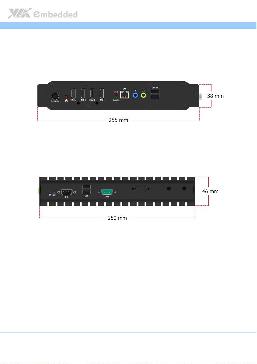
255 mm x 250 mm x 46 mm
Weight
Weight
WeightWeight
3.7 Kg. (net weight)
imension (Length
imension (imension (
Length x
LengthLength
x Width
Width x
x x
WidthWidth
x Height
Height))))
x x
HeightHeight
Video Wall Mini User Manual
Video Wall Mini User ManualVideo Wall Mini User Manual
Environmental Specification
Environmental Specification
Environmental SpecificationEnvironmental Specification
Operating Temperature
Operating Temperature
Operating TemperatureOperating Temperature
0°C ~ 45°C (with 2.5” SATA SSD)
0°C ~ 50°C (with mSATA)
Operating Humidity
Operating Humidity
Operating HumidityOperating Humidity
0% ~ 90%, relative humidity, non-condensing
Storage
Storage Temperature
Temperature
StorageStorage
Temperature Temperature
10°C ~ 60°C @ 90%, non-condensing
Vibration Loading during operation
Vibration Loading during operation (with
Vibration Loading during operationVibration Loading during operation
5Grms, IEC 60068-2-64, random, 5~500Hz, 1hr/axis
Shock during operation (with
Shock during operation (with 2.5”
Shock during operation (with Shock during operation (with
50G, IEC 60068-2-27, half size, 11ms duration
(with 2.5”
(with (with
2.5” SATA
SATA SSD
2.5” 2.5”
SATA SATA
2.5” SATA
2.5” 2.5”
SSD))))
SSDSSD
SATA SSD
SSD))))
SATA SATA
SSDSSD
Certification Requirements
Certification Requirements
Certification RequirementsCertification Requirements
EMC Approved
EMC Approved
EMC ApprovedEMC Approved
CE FCC, Class B, CCC
Software Compatibility
Software Compatibility
Software Compatibility Software Compatibility
Operating System
Operating System
Operating SystemOperating System
Microsoft Windows 7
Microsoft Windows Embedded Standard 7 with MagicView
Reminder:
Reminder:
Reminder:Reminder:
Use HDMI extender if the HDMI cable is over 10 meters (32.8 feet) long to overcome transmission
problem.
NNNNote:
ote:
ote:ote:
As the operating temperature provided in the specifications is a result of the test performed in VIA’s
chamber, a number of variables can influence this result. Please note that the working temperature may
vary depending on the actual situation and environment. It is highly suggested to execute a solid
testing and take all the variables into consideration when building the system. Please ensure that the
system runs well under the operating temperature in terms of application.
6
Page 19
Video Wall Mini User Manual
Video Wall Mini User Manual
Video Wall Mini User ManualVideo Wall Mini User Manual
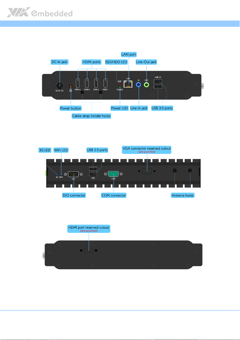
1.3. Panel Layout
Figu
Figure
re 1111: Front side layout label
: Front side layout label
FiguFigu
re re
: Front side layout label: Front side layout label
Figure
Figure 2222: Right side layout label
: Right side layout label
Figure Figure
: Right side layout label: Right side layout label
Figure
Figure 3333: Rear side layout label
: Rear side layout label
Figure Figure
: Rear side layout label: Rear side layout label
7
Page 20
Video Wall Mini User Manual
Video Wall Mini User Manual
Video Wall Mini User ManualVideo Wall Mini User Manual
Figure
Figure 4444: Bottom side layout label
: Bottom side layout label
Figure Figure
: Bottom side layout label: Bottom side layout label
8
Page 21
Video Wall Mini User Manual
Video Wall Mini User Manual
Video Wall Mini User ManualVideo Wall Mini User Manual
1.4. Dimensions
Figure
Figure 5555:
: Front
Front vvvview
iew dim
dimensions
Figure Figure
: :
Front Front
iew iew
dimdim
ensions
ensionsensions
Figure
Figure 6666:
: Side
Side vvvview d
iew dimensions
Figure Figure
: :
Side Side
iew diew d
imensions
imensionsimensions
9
Page 22
Video Wall Mini User Manual
Video Wall Mini User Manual
Video Wall Mini User ManualVideo Wall Mini User Manual
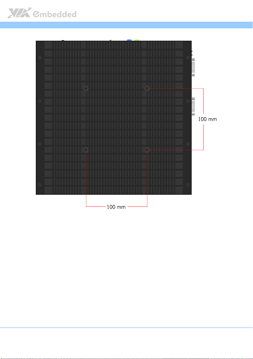
Figure
Figure 7777:
: Bottom
Figure Figure
Bottom vvvview d
: :
BottomBottom
iew dimensions
imensions
iew diew d
imensionsimensions
10
Page 23
Video Wall Mini User Manual
2.
2. External
External I/O
2.2.
External External
and Functionality
and Functionality
and Functionalityand Functionality
The Video Wall Mini has a wide selection of interfaces located on the front
and right panel as part of the external I/O.
I/O Pin Descriptions
I/OI/O
Pin Descriptions
Pin Descriptions Pin Descriptions
Video Wall Mini User Manual
Video Wall Mini User ManualVideo Wall Mini User Manual
2.1. Front Panel I/O
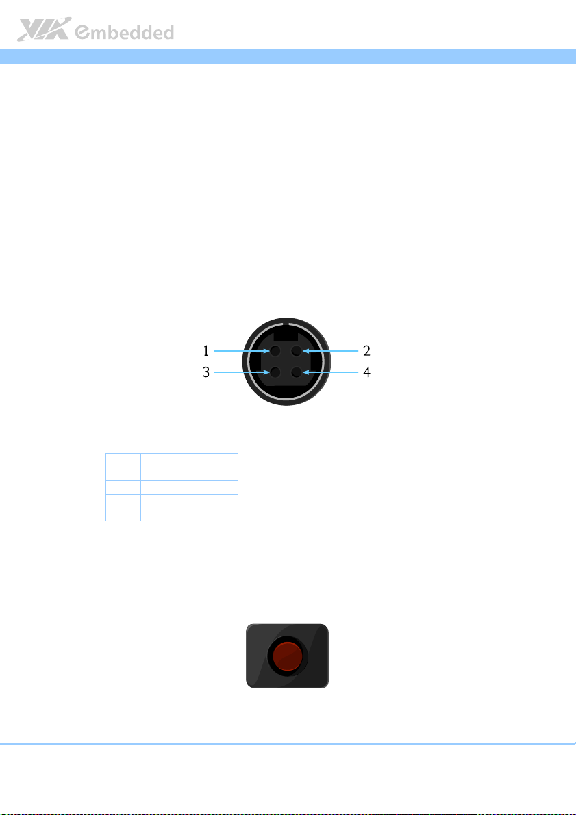
2.1.1. DC-In Jack (Power Input)
The Video Wall Mini comes with a 4-hole DC-In jack that carries 12V DC
external power input.
Figure
Figure 8888:
: DC
DC----In
In jack
jack diagram
Figure Figure
: :
DCDC
InIn
jackjack
diagram
diagram diagram
Table
Table 1111:
Table Table
Pin
Pin Signal
PinPin
1 +12V
2 +12V
3 GND
4 GND
: DC
DC----In jack
In jack pinout
: :
DCDC
In jackIn jack
Signal
SignalSignal
pinout
pinout pinout
2.1.2. Power Button
The Video Wall Mini comes with a Power On/Off button, that supports Soft
Power-On/Off (Instant Off or 4 second delay) and Suspend.
Figure
Figure 9999:
: Power button
Figure Figure
Power button diagram
: :
Power button Power button
11
diagram
diagramdiagram
Page 24
Video Wall Mini User Manual
2.1.3. HDMI
®
Port
Video Wall Mini User Manual
Video Wall Mini User ManualVideo Wall Mini User Manual
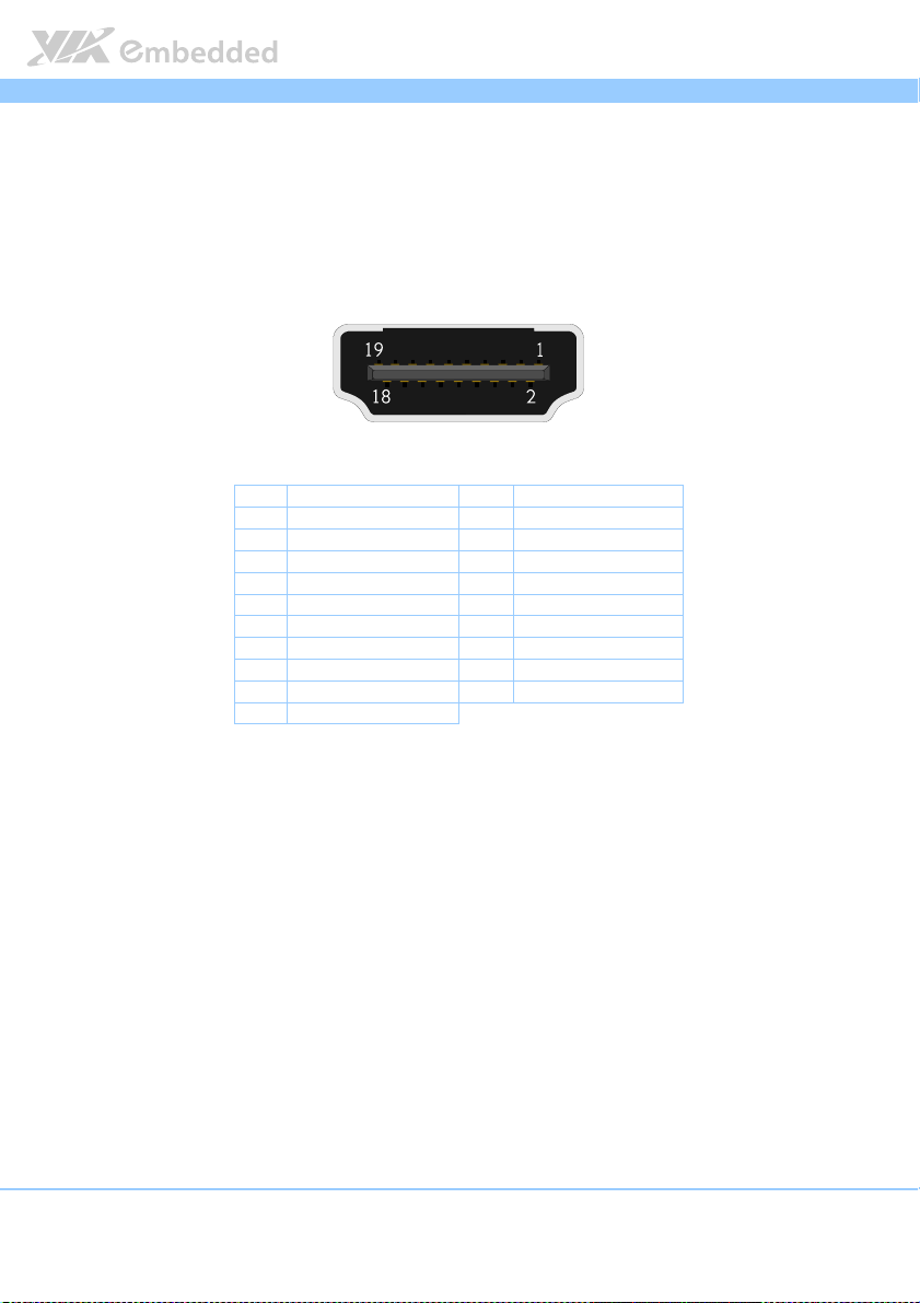
The Video Wall Mini provides four HDMI® ports (19-pin HDMI Type A
receptacle connector) via discrete S3 5400E graphics processor onboard. The
HDMI® ports allow you to connect up to four digital video devices which
utilize a high definition video playback. The pinout of the HDMI® port is
shown below.
Figure
Figure 10
10: HDMI
Figure Figure
1010
Table
Table 2222: HDMI
Table Table
: HDMI
: HDMI: HDMI
: HDMI
: HDMI: HDMI
®®®®
port diagram
port diagram
port diagram port diagram
Pin
Pin Signal
Signal Pin
PinPin
SignalSignal
1 TX2+ 2 GND
3 TX2- 4 TX1+
5 GND 6 TX17 TX0+ 8 GND
9 TX0- 10 TXC+
11 GND 12 TXC13 - 14 15 DDCSCL 16 DDCSDA
17 GND 18 +5V
19 Hot Plug Detect
®®®®
port pinout
port pinout
port pinout port pinout
Pin Signal
PinPin
Signal
SignalSignal
12
Page 25
Video Wall Mini User Manual
Video Wall Mini User Manual
Video Wall Mini User ManualVideo Wall Mini User Manual
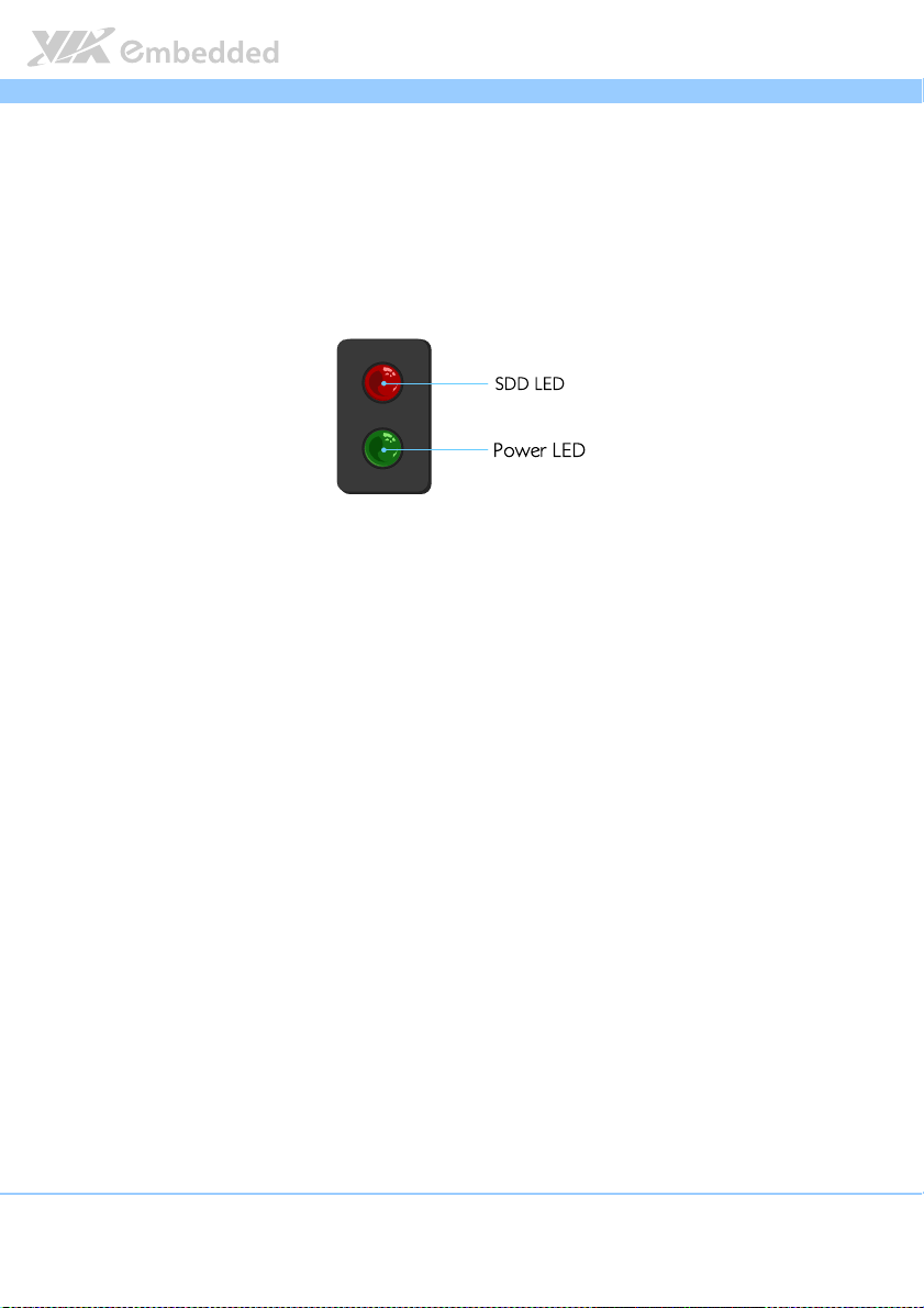
2.1.4. LED Indicators (Power LED and SATA SSD LED)
There are two LEDs on the front panel of Video Wall Mini that indicate the
status of the system:
Power LED flashes in green and indicates system’s power status.
SATA SSD LED flashes in red and indicates hard drive storage activity
for 2.5” SATA SSD.
Figure
Figure 11
11:
: Power and
Figure Figure
Power and SATA
1111
: :
Power and Power and
SATA SSD
SSD LED indicator
SATA SATA
SSDSSD
LED indicator diagram
LED indicator LED indicator
diagram
diagram diagram
13
Page 26
Video Wall Mini User Manual
Video Wall Mini User Manual
Video Wall Mini User ManualVideo Wall Mini User Manual
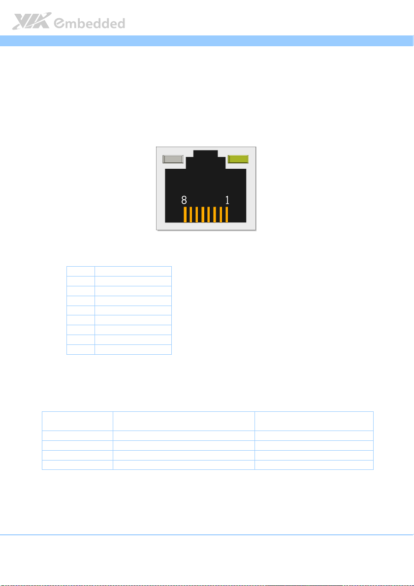
2.1.5. RJ-45 LAN Port (Gigabit Ethernet)
The Video Wall Mini is equipped with a Gigabit Ethernet LAN port. The
Gigabit Ethernet LAN port is using 8 Position 8 Contact (8P8C) receptacle
connector or commonly referred to as RJ-45. It is fully compliant with IEEE
802.3 (10BASE-T), 802.3u (100BASE-TX), and 802.3ab (1000BASE-T) standards.
The pinout of the LAN port is shown below.
Figure
Figure 12
12:
: RJ
RJ----45 LAN port
Figure Figure
1212
Table
Table 3333:
Table Table
45 LAN port diagram
: :
RJRJ
45 LAN port 45 LAN port
Pin
Pin Signal
PinPin
1 LAN1_TD0+
2 LAN1_TD03 LAN1_TD1+
4 LAN1_TD15 LAN1_TD2+
6 LAN1_TD27 LAN1_TD3+
8 LAN1_TD3-
: RJ
RJ----45 LAN port
45 LAN port pinout
: :
RJRJ
45 LAN port45 LAN port
Signal
SignalSignal
diagram
diagramdiagram
pinout
pinout pinout
The LAN port has two individual LED indicators located on the front side to
show its Active/Link status and Speed status.
Link LED
Link Off Off Off
Speed_10Mbit Off Flash in Orange color
Speed_100Mbit The LED is always On in Green color Flash in Orange color
Speed_1000Mbit The LED is always On in Orange color Flash in Orange color
Table
Table 4444:
: RJ
RJ----45 LAN port
Table Table
45 LAN port color de
: :
RJRJ
45 LAN port45 LAN port
(Left LED on RJ
(Left LED on RJ----45 connector)
(Left LED on RJ(Left LED on RJ
color definition
color de color de
finition
finitionfinition
Link LED
Link LEDLink LED
45 connector)
45 connector)45 connector)
Active LED
Active LED
(Right LED on RJ
(Right LED on RJ----45 connector)
(Right LED on RJ(Right LED on RJ
Active LEDActive LED
45 connector)
45 connector)45 connector)
14
Page 27
Video Wall Mini User Manual
Video Wall Mini User Manual
Video Wall Mini User ManualVideo Wall Mini User Manual
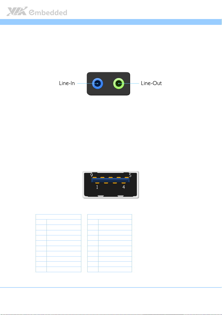
2.1.6. Audio Jacks
The Video Wall Mini has High Definition Audio through two 3.5 mm audio
jacks for Line-Out and Line-In. The Line-In jack is for connecting to an external
audio device such as CD player, tape player, etc., while Line-Out jack is for
connecting to external to speakers or headphones.
Figure
Figure 13
13: Audio jack receptacle stack diagram
Figure Figure
: Audio jack receptacle stack diagram
1313
: Audio jack receptacle stack diagram: Audio jack receptacle stack diagram
2.1.7. USB 3.0 Port
The Video Wall Mini is equipped with two USB 3.0 ports. The USB 3.0 port
has a maximum data transfer rate up to 5 Gbps and offers a backward
compatible with previous USB 2.0 specifications. It gives complete Plug and
Play and hot swap capability for external devices. The pinout of the typical
USB 3.0 port is shown below.
Figure
Figure 14
14: USB
: USB 3.0
3.0 port diagram
Figure Figure
1414
Table
Table 5555: USB
: USB 3.0
Table Table
: USB: USB
port diagram
: USB: USB
3.0 3.0
port diagram port diagram
USB 3.0 port 1
USB 3.0 port 1 USB 3.0 port 2
USB 3.0 port 1USB 3.0 port 1
Pin
Pin Signal
Signal Pin
PinPin
SignalSignal
1 +5V 1 +5V
2 Data1- 2 Data23 Data1+ 3 Data2+
4 GND 4 GND
5 RX1- 5 RX26 RX1+ 6 RX2+
7 GND 7 GND
8 TX1- 8 TX29 TX1+
3.0 port pinout
port pinout
3.0 3.0
port pinout port pinout
Pin Signal
PinPin
9 TX2+
USB 3.0 port 2
USB 3.0 port 2USB 3.0 port 2
Signal
SignalSignal
15
Page 28

Video Wall Mini User Manual
Video Wall Mini User Manual
Video Wall Mini User ManualVideo Wall Mini User Manual
2.2. Right Side Panel
2.2.1. LED Indicators (3G/3.5G and WLAN)
There are two LEDs on the right side panel of the Video Wall Mini that
indicate the status of the 3G/3.5G and WLAN (WiFi) connectivity:
3G/3.5G flashes in blue and indicates the activity status of 3G/3.5G
connectivity.
WLAN LED flashes in blue and indicates activity status of WLAN
(WiFi).
Figure
Figure 15
15:
: 3G/3.5
Figure Figure
3G/3.5GGGG and WLAN LED
1515
: :
3G/3.53G/3.5
2.2.2. Digital I/O Connector
The Video Wall Mini system is equipped with 8-bit Digital I/O (GPIO)
connector (D-sub 9-pin), which offers Digital I/O communication interface. The
Digital I/O default settings supports up to four GPO and four GPI signals. The
pinout of the Digital I/O connector is shown below.
and WLAN LED indi
and WLAN LED and WLAN LED
indicator
indiindi
cator
catorcator
Figure
Figure 16
16: DIO
: DIO connector
Figure Figure
1616
: DIO : DIO
connector diagram
connectorconnector
diagram
diagram diagram
Pin
Pin Signal
Signal
PinPin
SignalSignal
1 GPO_37
2 GPO_35
3 GPI_53
4 GPI_51
5 GND
6 GPO_36
7 GPO_34
8 GPI_52
Table
Table 6666:
Table Table
9 GPI_50
: DIO connect
DIO connector
: :
DIO connectDIO connect
or pinout
pinout
oror
pinout pinout
16
Page 29

Video Wall Mini User Manual
Video Wall Mini User Manual
Video Wall Mini User ManualVideo Wall Mini User Manual
2.2.3. USB 2.0 Port
The Video Wall Mini has two USB 2.0 ports on the right side panel. Each port
gives complete Plug & Play and hot swapping capability for external devices.
The USB interface complies with USB UHCI, Rev. 2.0. The USB 2.0 pinout is
shown below.
Figure
Figure 17
17: USB
: USB 2.0
2.0 port diagram
Figure Figure
1717
Table
Table 7777: USB
: USB 2.0
Table Table
: USB: USB
port diagram
: USB: USB
2.0 2.0
port diagram port diagram
USB
USB port
port 1111 USB
USBUSB
Pin
Pin Signal
PinPin
1 VCC 1 VCC
2 USB1_data- 2 USB2_data3 USB1_data+ 3 USB2_data+
4 GND
port port
Signal Pin
SignalSignal
2.0 port pinout
port pinout
2.0 2.0
port pinout port pinout
USB port
USBUSB
Pin Signal
Signal
PinPin
SignalSignal
4 GND
port 2222
port port
17
Page 30

Video Wall Mini User Manual
Video Wall Mini User Manual
Video Wall Mini User ManualVideo Wall Mini User Manual
2.2.4. COM Connector
The Video Wall Mini system provides one COM connector for serial
communications. The COM connector can be configured to operate in RS232/RS-422/RS-485 mode by adjusting the BIOS setup items. However, the
default setting of COM connector is the standard RS-232. The pinout of the
COM connector is shown below.
Figure
Figure 18
18: COM
: COM connector
Figure Figure
1818
: COM : COM
Pin
Pin Signal
PinPin
Table
Table 8888: COM
: COM connector
Table Table
: COM : COM
connector diagram
connectorconnector
1 DCD
2 RxD
3 TxD
4 DTR
5 GND
6 DSR
7 RTS
8 CTS
9 RI
connector pino
connectorconnector
Signal
SignalSignal
diagram
diagram diagram
pinout
ut
pino pino
utut
18
Page 31

Video Wall Mini User Manual
3.
3. Onboard Connector
Onboard Connector and
3.3.
Onboard ConnectorOnboard Connector
Headers
Headers
HeadersHeaders
This chapter provides information about the onboard connectors and pin
headers of VIA Video Wall Mini system’s mainboard.
Video Wall Mini User Manual
Video Wall Mini User ManualVideo Wall Mini User Manual
and Pin
and and
Pin
Pin Pin
3.1. LPC Connector
The Video Wall Mini has one LPC connector for debugging purpose. The
connector is labeled as “JLPC1”. The pinout of the connector is shown below.
Figure
Figure 19
19: LPC connector diagram
Figure Figure
Table
Table 9999: LPC
Table Table
: LPC connector diagram
1919
: LPC connector diagram: LPC connector diagram
Pin
Pin Signal
Signal
PinPin
SignalSignal
1 GND
2 LPCAD2
3 LPCAD3
4 LPCAD1
5 -LPCFRAME
6 LPCAD0
7 LPC33CLK
8 -LPCRST
: LPC connector
: LPC : LPC
9 +3.3V
connector pinout
connectorconnector
pinout
pinout pinout
19
Page 32

Video Wall Mini User Manual
Video Wall Mini User Manual
Video Wall Mini User ManualVideo Wall Mini User Manual
3.2. VGA Pin Header
The Video Wall Mini mainboard has an onboard VGA pin header that allows
connection of VGA connector cable for analog VGA monitor. The onboard
VGA pin header is labeled as “JVGA1”. The pinout of the VGA pin header is
shown below.
Figure
Figure 20
20: VGA pin header diagram
Figure Figure
: VGA pin header diagram
2020
: VGA pin header diagram: VGA pin header diagram
Pin
Pin Signal
Table
Table 10
10: VGA pin header pinout
: VGA pin header pinout
Table Table
1010
: VGA pin header pinout: VGA pin header pinout
Signal Pin
PinPin
SignalSignal
1 GND 2 +5V_CRT
3 VGA-R 4 VGA-SPD
5 VGA-G 6 VGA-SPCLK
7 VGA-B 8 VGA HS
9 GND 10 VGA VS
11 GND 12 GND
13 GND 14 NC
Pin Signal
Signal
PinPin
SignalSignal
20
Page 33

Video Wall Mini User Manual
Video Wall Mini User Manual
Video Wall Mini User ManualVideo Wall Mini User Manual
3.3. SPI Pin Header
The Video Wall Mini mainboard has one SPI (Serial Peripheral Interface) pin
header used to connect to the SPI BIOS programming fixture for updating the
SPI flash ROM. The SPI pin header is labeled as “SPI1”. The pinout of the SPI
pin header is shown below.
Figure
Figure 21
21:
: SPI pin header diagram
Figure Figure
Table
Table 11
Table Table
SPI pin header diagram
2121
: :
SPI pin header diagramSPI pin header diagram
Pin
Pin Signal
Signal Pin
PinPin
SignalSignal
1 SPIVCC 2 GND
3 MSPISA 4 MSPICLK
5 MSPIDI 6 MSPIDO
11:
1111
7 — 8 -PCIRST
: SPI pin header
SPI pin header pinout
: :
SPI pin headerSPI pin header
pinout
pinout pinout
Pin Signal
Signal
PinPin
SignalSignal
21
Page 34

Video Wall Mini User Manual
Video Wall Mini User Manual
Video Wall Mini User ManualVideo Wall Mini User Manual
3.4. System Temperature Sensor Pin Header
The Video Wall Mini supports an onboard pin header (3-pin) that allows the
connection of a temperature sensor cable for detecting the system’s internal
temperature. The temperature data can be seen in the BIOS Setup Utility. The
pin header is labeled as “J7”. The pinout of the temperature sensor pin header
is shown below.
Figure
Figure 22
22:
: System
System ttttemperature
Figure Figure
2222
: :
System System
emperature sensor
emperature emperature
sensor pin header diagram
pin header diagram
sensor sensor
pin header diagrampin header diagram
Pin
Pin Signal
Signal
PinPin
SignalSignal
1 TMPIN2
2 TMPIN2
Table
Table 12
12:
Table Table
1212
: System
System ttttemperature
: :
System System
3 HWMGND
emperature sensor
emperature emperature
sensor pin header
sensor sensor
pin header pinout
pin headerpin header
pinout
pinout pinout
22
Page 35

Video Wall Mini User Manual
4.
4. Onboard Jumpers
Onboard Jumpers
4.4.
Onboard JumpersOnboard Jumpers
Jumper Description
Jumper Description
Jumper DescriptionJumper Description
A jumper consists of pair conductive pins used to close in or bypass an
electronic circuit to set up or configure particular feature using a jumper cap.
The jumper cap is a small metal clip covered by plastic. It performs like a
connecting bridge to short (connect) the pair of pins. The usual colors of the
jumper cap are black/red/blue/white/yellow.
Jumper Setting
Jumper Setting
Jumper SettingJumper Setting
There are two settings of the jumper pin: “Short
“Short
Short”””” when a jumper cap is placed on the pair of pins. The pins are ”O
ShortShort
the jumper cap is removed.
In addition, there are jumpers that have three or more pins, and some pins are
arranged in series. In case of a jumper with three pins, place the jumper cap on
pin 1 and pin 2 or pin 2 and 3 to Short
Some jumper size is small or mounted on the crowded location on the board
that makes it difficult to access. Therefore, using a long-nose pliers in installing
and removing the jumper cap is very helpful.
Short it.
ShortShort
Short and Open
ShortShort
Video Wall Mini User Manual
Video Wall Mini User ManualVideo Wall Mini User Manual
Open”. The pins are
OpenOpen
”Open
pen”””” if
”O”O
penpen
Figure
Figure 23
23: Jumper settings example
Figure Figure
: Jumper settings example
2323
: Jumper settings example: Jumper settings example
Caution:
Caution:
Caution:Caution:
Make sure to install the jumper cap on the correct pins. Installing it in the wrong pin might cause
damage and malfunction.
23
Page 36

Video Wall Mini User Manual
Video Wall Mini User Manual
Video Wall Mini User ManualVideo Wall Mini User Manual
4.1. System Reset Jumper
To restart the hardware, temporarily close the jumper of the 2-pin reset pin
header. The reset pin header is labeled as “JRST1”.
Figure
Figure 24
24:
: System
System rrrreset jumper
Figure Figure
2424
: :
System System
eset jumper diagram
eset jumpereset jumper
diagram
diagram diagram
Setting
Table
Table 13
13:
Table Table
1313
: System
System rrrreset j
: :
eset jumper settings
System System
eset jeset j
Setting Pin 1
SettingSetting
Normal (default) Open Open
System Reset Short Short
umper settings
umper settingsumper settings
Pin 1 Pin 2
Pin 1Pin 1
Pin 2
Pin 2Pin 2
24
Page 37

Video Wall Mini User Manual
Video Wall Mini User Manual
Video Wall Mini User ManualVideo Wall Mini User Manual
4.2. Reset CMOS RAM Jumper
The onboard CMOS RAM stores system configuration data and has an onboard
battery power supply. To reset the CMOS settings, set the jumper on pins 2
and 3 while the system is off. Return the jumper to pins 1 and 2 afterwards.
Setting the jumper while the system is on will damage the mainboard. The
default setting is on pins 1 and 2. The Reset CMOS RAM jumper is labeled as
“J10”.
Figure
Figure 25
25: Res
: Reset CMOS RAM jumper
Figure Figure
et CMOS RAM jumper diagram
2525
: Res: Res
et CMOS RAM jumperet CMOS RAM jumper
diagram
diagram diagram
Setting
Setting Pin 1
SettingSetting
Normal (default) Short Short Open
Table
Table 14
14: Reset CMOS RAM jumper settings
: Reset CMOS RAM jumper settings
Table Table
1414
: Reset CMOS RAM jumper settings: Reset CMOS RAM jumper settings
Note:
Note:
Note:Note:
Except when clearing the RTC RAM, never remove the cap from the Reset CMOS RAM jumper (J10)
default position. Removing the cap will cause system boot failure. Avoid resetting/clearing the CMOS
while the system is on; it will damage the system mainboard.
Reset/Clear CMOS Open Short Short
Pin 1 Pin 2
Pin 1Pin 1
Pin 2 Pin 3
Pin 2Pin 2
Pin 3
Pin 3Pin 3
25
Page 38

Video Wall Mini User Manual
Video Wall Mini User Manual
Video Wall Mini User ManualVideo Wall Mini User Manual
4.3. SPI Address Select Jumper
Selection of address for SPI pin header is controlled by the jumper labeled as
“J6”. The jumper settings are shown below.
Figure
Figure 26
26:
: SPI
SPI aaaaddress select jumper
Figure Figure
ddress select jumper diagram
2626
: :
SPI SPI
ddress select jumperddress select jumper
diagram
diagram diagram
Setting
Table
Table 15
15:
TableTable
1515
Setting Pin 1
SettingSetting
MSPISS0 (default) Short Short Open
MSPISS1 Open Short Short
: SPI
SPI aaaaddress select jumper settings
ddress select jumper settings
: :
SPI SPI
ddress select jumper settingsddress select jumper settings
Pin 1 Pin 2
Pin 1Pin 1
Pin 2 Pin 3
Pin 2Pin 2
Pin 3
Pin 3Pin 3
26
Page 39

Video Wall Mini User Manual
Video Wall Mini User Manual
Video Wall Mini User ManualVideo Wall Mini User Manual
4.4. Recovery BIOS Jumper
The Video Wall Mini mainboard offers a BIOS recovery jumper labeled as
“JRC_BIOS1”. To recover the default BIOS program, set the jumper on pins 1
and 2 while the system is off. Return the jumper to pins 2 and 3 afterwards.
The default setting is on pins 2 and 3.
Figure
Figure 27
27: Re
: Recovery BIOS
Figure Figure
covery BIOS jumper diagram
2727
: Re: Re
covery BIOScovery BIOS
jumper diagram
jumper diagram jumper diagram
Setting
Table
Table 16
16: Re
TableTable
1616
Setting Pin 1
SettingSetting
Enable Short Short Open
: Recovery BIOS
covery BIOS jumper settings
: Re: Re
covery BIOScovery BIOS
Disable (default) Open Short Short
jumper settings
jumper settings jumper settings
Pin 1 Pin 2
Pin 1Pin 1
Pin 2 Pin 3
Pin 2Pin 2
Pin 3
Pin 3Pin 3
27
Page 40

Video Wall Mini User Manual
Video Wall Mini User Manual
Video Wall Mini User ManualVideo Wall Mini User Manual
4.5. VDD/VSUSVDD Mode Select Jumper
Selection of VDD/VUSVDD mode jumper is controlled by the jumper labeled
as “J9”. The jumper settings are shown below.
Figure
Figure 28
28:
: VDD/VSUS
Figure Figure
VDD/VSUSVDD
2828
: :
VDD/VSUSVDD/VSUS
VDD mmmmode
ode select jumper diagram
VDD VDD
select jumper diagram
ode ode
select jumper diagramselect jumper diagram
Setting
Table
Table 17
17:
Table Table
1717
Setting Pin 1
SettingSetting
VDD = 1.0 V Open Open Open
VDD = 0.9V Short Short Open
VDD Control by MPSVID (Default) Open Short Short
: VDD/VSUSVDD
VDD/VSUSVDD mmmmode
: :
VDD/VSUSVDD VDD/VSUSVDD
ode select jumper settings
select jumper settings
ode ode
select jumper settingsselect jumper settings
Pin 1 Pin 2
Pin 1Pin 1
Pin 2 Pin 3
Pin 2Pin 2
Pin 3
Pin 3Pin 3
28
Page 41

Video Wall Mini User Manual
5.
5. Hardware Inst
Hardware Installation
5.5.
Hardware InstHardware Inst
This chapter provides the information about hardware installation procedures.
allation
allationallation
Video Wall Mini User Manual
Video Wall Mini User ManualVideo Wall Mini User Manual
5.1. How to remove the top cover
Step 1
Step 1
Step 1Step 1
Remove the top screws (x4) of front and rear plates, and remove the eight
screws of the top cover as indicated in the figure below.
Figure
Figure 29
29:
: Removing top cover
Figure Figure
Step
Step 2222
Step Step
Carefully lift up the top cover.
29
Removing top cover
2929
: :
Removing top coverRemoving top cover
Page 42

Video Wall Mini User Manual
Video Wall Mini User Manual
Video Wall Mini User ManualVideo Wall Mini User Manual
5.2. How to reinstall the top cover
Step 1
Step 1
Step 1Step 1
On the inner side of the top cover, spread the thermal grease evenly on the
center area of the heat pipe plate before reinstalling the top cover. Using a
plastic protector, use your finger to spread the grease.
Figure
Figure 30
30:
: Spreading thermal
Figure Figure
Spreading thermal grease
3030
: :
Spreading thermal Spreading thermal
grease
greasegrease
Reminder
Reminder::::
ReminderReminder
Every time the user takes off the top cover, the amount of thermal grease (between the heat pipe plate
and CPU heatsink) may decrease. Therefore, adding a small amount of thermal grease is advisable. Use
the thermal grease (in tube syringe) provided in the package.
30
Page 43

Video Wall Mini User Manual
Step
Step 2222
Step Step
Video Wall Mini User Manual
Video Wall Mini User ManualVideo Wall Mini User Manual
Align the top cover over the mounting holes on the chassis.
Figu
Figure
re 31
31:
: Aligning the top cover
FiguFigu
Aligning the top cover
re re
3131
: :
Aligning the top coverAligning the top cover
Step
Step 3333
Step Step
Secure the top cover with sixteen mounting screws as indicated in the figure
below.
Figure
Figure 32
32:
: Securing the top cover
Figure Figure
Securing the top cover
3232
: :
Securing the top coverSecuring the top cover
31
Page 44

Video Wall Mini User Manual
Video Wall Mini User Manual
Video Wall Mini User ManualVideo Wall Mini User Manual
5.3. How to install the DDR3 SODIMM memory
Step 1
Step 1
Step 1Step 1
Locate the DDR3 SODIMM memory socket. Align the notch on the memory
module with the notch on the SODIMM socket.
Step
Step 2222
Step Step
Gently insert the DDR3 memory module into the SODIMM socket at a 30°
angle.
Figure
Figure 33
33:
: Installing DDR3 SODIMM
Figure Figure
Installing DDR3 SODIMM module
3333
: :
Installing DDR3 SODIMM Installing DDR3 SODIMM
module
modulemodule
Step
Step 3333
Step Step
Push down the memory module until it snaps into place.
32
Page 45

Video Wall Mini User Manual
Video Wall Mini User Manual
Video Wall Mini User ManualVideo Wall Mini User Manual
5.4. How to remove the DDR3 SODIMM memory
Step 1
Step 1
Step 1Step 1
To disengage the locking clips, push the locking clips horizontally outward
away from the SODIMM memory module.
Figure
Figure 34
34: Disengaging the SODIMM locking clips
Figure Figure
Step 2
Step 2
Step 2Step 2
When the locking clips have cleared, the SODIMM memory module will
automatically pop up to the 30 degree angle. Remove the memory module.
: Disengaging the SODIMM locking clips
3434
: Disengaging the SODIMM locking clips: Disengaging the SODIMM locking clips
Figure
Figure 35
35: Removing the memory mo
Figure Figure
: Removing the memory module
3535
: Removing the memory mo: Removing the memory mo
dule
duledule
33
Page 46

Video Wall Mini User Manual
Video Wall Mini User Manual
Video Wall Mini User ManualVideo Wall Mini User Manual
5.5. How to install the 2.5-inch SATA SSD
Step 1
Step 1
Step 1Step 1
Remove four screws and pull up hard drive bay.
Figure
Figure 36
36:
: Removing SATA
Figure Figure
Removing SATA SSD
3636
: :
Removing SATA Removing SATA
Step
Step 2222
Step Step
Attach the hard drive bay to the 2.5-inch SATA SSD.
SSD bay
bay
SSDSSD
bay bay
Figure
Figure 37
37:
: Installing
Figure Figure
Installing hard drive
3737
: :
Installing Installing
hard drive bay
hard drive hard drive
bay to 2.5
baybay
to 2.5----inch SATA
inch SATA SSD
to 2.5 to 2.5
inch SATA inch SATA
SSD
SSDSSD
34
Page 47

Video Wall Mini User Manual
Step
Step 3333
Step Step
Video Wall Mini User Manual
Video Wall Mini User ManualVideo Wall Mini User Manual
Reinstall the hard drive bay with the 2.5-inch SATA SSD, and secure it with
screws. Connect the other end of SATA data and power cable into the SATA
SSD.
Figure
Figure 38
38:
: Instal
Installing
ling SATA
SATA SSD
SSD and connecting SATA cables
Figure Figure
3838
: :
InstalInstal
ling ling
SATA SATA
and connecting SATA cables
SSDSSD
and connecting SATA cables and connecting SATA cables
35
Page 48

Video Wall Mini User Manual
Video Wall Mini User Manual
Video Wall Mini User ManualVideo Wall Mini User Manual
5.6. How to install the mSATA module
Step
Step 1111
Step Step
Align the notch on the mSATA module with the notch on the mini PCIe slot
then insert the module at a 30° angle.
Figure
Figure 39
39:
: Inserting mSATA module
Figure Figure
SSSStep
Once the mSATA module has been fully inserted, push down the module until
the screw hole aligns with the standoff hole then secure it with two screws.
Inserting mSATA module
3939
: :
Inserting mSATA moduleInserting mSATA module
tep 2222
tep tep
Figure
Figure 40
40:
: Securing
Securing mSATA module
Figure Figure
4040
: :
SecuringSecuring
mSATA module
mSATA module mSATA module
36
Page 49

Video Wall Mini User Manual
Video Wall Mini User Manual
Video Wall Mini User ManualVideo Wall Mini User Manual
5.7. How to insert SIM card
Step
Step 1111
Step Step
Push back firmly the SIM card socket to unlock and open. Pull up the socket
and place in the SIM card.
Figure
Figure 41
41: Inserting
Figure Figure
: Inserting 3G/3.5
4141
: Inserting : Inserting
3G/3.5GGGG SIM card
SIM card
3G/3.53G/3.5
SIM card SIM card
Note:
Note:
Note:Note:
Ensure the angled corner of the SIM card is placed in the correct way before closing the socket.
Step
Step 2222
Step Step
Gently close the socket by pulling down the SIM socket that contains the SIM
card then carefully lock the SIM socket.
37
Page 50

Video Wall Mini User Manual
Video Wall Mini User Manual
Video Wall Mini User ManualVideo Wall Mini User Manual
5.8. How to install 3G/3.5G module and antenna
Step
Step 1111
Step Step
Align the notch on the 3G/3.5G module (EMIO-1541-00A1) with the notch on
the mini PCIe card slot then insert the module at a 30° angle.
Figure
Figure 42
42: Inserting
Figure Figure
: Inserting 3G/3.5
4242
: Inserting : Inserting
3G/3.5GGGG module
module
3G/3.53G/3.5
module module
38
Page 51

Video Wall Mini User Manual
Step
Step 2222
Step Step
Video Wall Mini User Manual
Video Wall Mini User ManualVideo Wall Mini User Manual
Once the 3G/3.5G module has been fully inserted, push down the module
until the screw holes align with the standoff holes. Then secure the module
with screw.
Figure
Figure 43
43: Securing
Figure Figure
: Securing 3G/3.5
4343
: Securing : Securing
3G/3.5GGGG module
module
3G/3.53G/3.5
module module
Step
Step 3333
Step Step
Remove the 3G/3.5G antenna hole cover from the right side panel of the
chassis.
39
Page 52

Video Wall Mini User Manual
Step
Step 4444
Step Step
Video Wall Mini User Manual
Video Wall Mini User ManualVideo Wall Mini User Manual
Insert the 3G/3.5G port connector into the antenna hole from the inside of the
chassis. Insert the washer and fasten it with the nut then install the external
antenna. Gently connect the mini coaxial cable of the 3G/3.5G port connector
to the mini RF connector on the 3G/3.5G module.
Figure
Figure 44
44:
: Installing
Figure Figure
Installing 3G/3.5
4444
: :
Installing Installing
3G/3.5GGGG antenna
antenna
3G/3.53G/3.5
antenna antenna
40
Page 53

Video Wall Mini User Manual
Video Wall Mini User Manual
Video Wall Mini User ManualVideo Wall Mini User Manual
5.9. How to install WLAN USB module and
antenna
Step
Step 1111
Step Step
Install the WLAN USB module (EMIO-1533-00A2) and secure it with two
screws. Then remove the antenna WLAN hole cover from the right side I/O
panel of the chassis.
Figure
Figure 45
45:
: Installing WLAN USB module
Figure Figure
Installing WLAN USB module
4545
: :
Installing WLAN USB moduleInstalling WLAN USB module
41
Page 54

Video Wall Mini User Manual
Step
Step 2222
Step Step
Video Wall Mini User Manual
Video Wall Mini User ManualVideo Wall Mini User Manual
Insert the WLAN port connector into the antenna hole from the inside of the
chassis. Insert the washer, fasten it with the nut and install the external antenna.
Gently connect the mini coaxial cable of the WLAN port connector to the
mini RF connector on the WLAN USB module.
Figure
Figure 46
46:
: Installing WLAN antenna
Figure Figure
Installing WLAN antenna
4646
: :
Installing WLAN antennaInstalling WLAN antenna
42
Page 55

Video Wall Mini User Manual
Step
Step 3333
Step Step
Video Wall Mini User Manual
Video Wall Mini User ManualVideo Wall Mini User Manual
Attach the WLAN board to board cable to the WLAN USB module. Then
attach the other end of the cable to the “JUSB2_3” pin header of the
mainboard.
Figure
Figure 47
47:
: Connecting WLAN board to board
Figure Figure
Connecting WLAN board to board cable
4747
: :
Connecting WLAN board to board Connecting WLAN board to board
cable
cablecable
43
Page 56

Page 57

Video Wall Mini User Manual
6.
6. BIOS Setup Utility
BIOS Setup Utility
6.6.
BIOS Setup UtilityBIOS Setup Utility
Video Wall Mini User Manual
Video Wall Mini User ManualVideo Wall Mini User Manual
6.1. Entering the BIOS Setup Utility
Power on the computer and press Delete
sequence to enter the BIOS Setup Utility. If the entry point has passed, restart
the system and try again.
Delete during the beginning of the boot
DeleteDelete
6.2. Control Keys
Up
Up Move up one row
UpUp
Down
Down Move down one row
DownDown
Left
Left Move to the left in the navigation bar
LeftLeft
Right
Right Move to the right in the navigation bar
RightRight
EEEEnter
nter Access the highlighted item / Select the item
nternter
Esc
Esc Jumps to the Exit screen or returns to the previous screen
EscEsc
++++1 Increase the numeric value
----1 Decrease the numeric value
F1
F1 General help2
F1F1
FFFF2222 Previous value
FFFF3333 Load optimized defaults
FFFF4444 Save all the changes and exit
Note
Notessss::::
NoteNote
1. Must be pressed using the 10-key pad.
2. The General help contents are only for the Status Page and Option Page setup menus.
6.3. Getting Help
The BIOS Setup Utility provides a “General Help
accessed at any time by pressing F1
using and navigating the BIOS Setup Utility. Press Esc
45
General Help” screen. This screen can be
General HelpGeneral Help
F1. The help screen displays the keys for
F1F1
Esc to exit the help screen.
EscEsc
Page 58

Video Wall Mini User Manual
Video Wall Mini User Manual
Video Wall Mini User ManualVideo Wall Mini User Manual
6.4. System Overview
The System Overview screen is the default screen that is shown when the
BIOS Setup Utility is launched. This screen can be accessed by traversing the
navigation bar to the “Main” label.
Figure
Figure 48
48: Illustration of the Main menu screen
Figure Figure
: Illustration of the Main menu screen
4848
: Illustration of the Main menu screen: Illustration of the Main menu screen
6.4.1. BIOS Information
The content in this section of the screen shows the information about the
vendor, the Core version, UEFI specification version, the project version and
date & time of the project build.
6.4.2. Memory Information
This section shows the amount of memory that is installed on the hardware
platform.
6.4.3. System Language
This option allows the user to configure the language that the user wants to
use.
46
Page 59

Video Wall Mini User Manual
Video Wall Mini User Manual
Video Wall Mini User ManualVideo Wall Mini User Manual
6.4.4. System Date
This section shows the current system date. Press Tab
Shift+Tab
Shift+Tab to traverse left through the month, day, and year segments. The ++++
Shift+TabShift+Tab
and ---- keys on the number pad can be used to change the values. The weekday
name is automatically updated when the date is altered. The date format is
[Weekday, Month, Day, Year].
Tab to traverse right and
TabTab
6.4.5. System Time
This section shows the current system time. Press Tab
Shift+Tab
Shift+Tab to traverse left through the hour, minute, and second segments. The
Shift+TabShift+Tab
++++ and ---- keys on the number pad can be used to change the values. The time
format is [Hour : Minute : Second].
Tab to traverse right and
TabTab
47
Page 60

Video Wall Mini User Manual
Video Wall Mini User Manual
Video Wall Mini User ManualVideo Wall Mini User Manual
6.5. Advanced Settings
The Advanced Settings screen shows a list of categories that can provide
access to a sub-screen. Sub-screen links can be identified by the preceding
right-facing arrowhead.
Figure
Figure 49
49: Illustration of the Advanced Settings screen
Figure Figure
: Illustration of the Advanced Settings screen
4949
: Illustration of the Advanced Settings screen: Illustration of the Advanced Settings screen
The Advanced Settings screen contains the following links:
ACPI Settings
S5 RTC Wake Settings
CPU Configuration
SATA Configuration
USB Configuration
F71869 Super IO Configuration
F71869 H/W Monitor
Clock Generator Configuration
48
Page 61

Video Wall Mini User Manual
Video Wall Mini User Manual
Video Wall Mini User ManualVideo Wall Mini User Manual
6.5.1. ACPI Settings
ACPI grants the operating system direct control over system power
management. The ACPI Configuration screen can be used to set a number of
power management related functions.
Figure
Figure 50
50: Illustration of the ACPI Settings screen
Figure Figure
: Illustration of the ACPI Settings screen
5050
: Illustration of the ACPI Settings screen: Illustration of the ACPI Settings screen
6.5.1.1.
6.5.1.1. Enable Hibernation
6.5.1.1.6.5.1.1.
Enable/disable system ability to Hibernate.
6.5.1.2.
6.5.1.2. ACPI Sleep State
6.5.1.2.6.5.1.2.
Select the highest ACPI sleep state the system will enter when the SUSPEND
button is selected. Available options are: Suspend Disabled / S1 only (CPU
Stop Clock) /S3 only(Suspend to RAM) / Both S1 and S3 available for OS to
choose from.
Enable Hibernation
Enable HibernationEnable Hibernation
ACPI Sleep State
ACPI Sleep StateACPI Sleep State
49
Page 62

Video Wall Mini User Manual
Video Wall Mini User Manual
Video Wall Mini User ManualVideo Wall Mini User Manual
6.5.2. S5 RTC Wake Settings
Figure
Figure 51
51: Illustration of the
Figure Figure
6.5.2.1.
6.5.2.1. Wake system with Fixed Time
6.5.2.1.6.5.2.1.
Enable or disable system wake on alarm event. When enabled, system will
wake on the hr:min:sec specified.
: Illustration of the S5 RTC
5151
: Illustration of the : Illustration of the
Wake system with Fixed Time
Wake system with Fixed TimeWake system with Fixed Time
S5 RTC Wake Settings screen
Wake Settings screen
S5 RTC S5 RTC
Wake Settings screenWake Settings screen
6.5.2.2.
6.5.2.2. Wake system with Dynamic Time
6.5.2.2.6.5.2.2.
Enable or disable system wake on alarm event. When enabled, system will
wake on the current time + Increase minutes. Available options are 1 – 5.
Wake system with Dynamic Time
Wake system with Dynamic TimeWake system with Dynamic Time
50
Page 63

Video Wall Mini User Manual
Video Wall Mini User Manual
Video Wall Mini User ManualVideo Wall Mini User Manual
6.5.3. CPU Configuration
The CPU Configuration screen shows detailed information about the built-in
processor.
Figure
Figure 52
52: Illustration of
Figure Figure
: Illustration of CPU
5252
: Illustration of : Illustration of
CPU Configuration screen
Configuration screen
CPUCPU
Configuration screen Configuration screen
51
Page 64

Video Wall Mini User Manual
Video Wall Mini User Manual
Video Wall Mini User ManualVideo Wall Mini User Manual
6.5.4. SATA Configuration
The SATA Configuration screen allows the user to view and configure the
SATA configuration settings.
Figure
Figure 53
53: Illustration of SATA Configuratio
Figure Figure
: Illustration of SATA Configuration screen
5353
: Illustration of SATA Configuratio: Illustration of SATA Configuratio
n screen
n screenn screen
6.5.4.1.
6.5.4.1. SATA Mode
6.5.4.1.6.5.4.1.
SATA Mode
SATA ModeSATA Mode
This option allows the user to manually configure SATA controller for a
particular mode.
IDE Mode
IDE Mode
IDE ModeIDE Mode
Set this value to change the SATA to IDE mode.
AHCI Mode
AHCI Mode
AHCI ModeAHCI Mode
Set this value to change the SATA to AHCI mode.
52
Page 65

Video Wall Mini User Manual
Video Wall Mini User Manual
Video Wall Mini User ManualVideo Wall Mini User Manual
6.5.5. USB Configuration
The USB Configuration screen shows the number of connected USB devices.
Additionally, support for various USB features can be enabled or disabled.
Figure
Figure 54
54: Illustration of USB Configuration
Figure Figure
: Illustration of USB Configuration
5454
: Illustration of USB Configuration: Illustration of USB Configuration
6.5.5.1.
6.5.5.1. Legacy USB Support
6.5.5.1.6.5.5.1.
The Legacy USB Support feature has three options: Enabled, Disabled and
Auto. When set to Enabled, the system enables support for legacy USB
devices. When set to Disabled, the system disables support for legacy USB
devices. When set to Auto, the system automatically disables legacy support if
no USB Devices are connected.
6.5.5.2.
6.5.5.2. USB3.0 Support
6.5.5.2.6.5.5.2.
Enable/Disable USB3.0 (XHCI) Controller support.
Legacy USB Support
Legacy USB SupportLegacy USB Support
USB3.0 Support
USB3.0 SupportUSB3.0 Support
53
Page 66

Video Wall Mini User Manual
6.5.5.3.
6.5.5.3. XHCI Hand
6.5.5.3.6.5.5.3.
This is a workaround for Operating Systems without XHCI hand-off support.
The XHCI ownership change should be claimed by XHCI driver.
Enabl
Enabled
EnablEnabl
This option enables XHCI hand-off support.
Disabled
Disabled
DisabledDisabled
This option disables XHCI hand-off support.
6.5.5.4.
6.5.5.4. EHCI Hand
6.5.5.4.6.5.5.4.
This is a workaround feature for Operating Systems without EHCI hand-off
support. The EHCI ownership must be claimed by EHCI Driver.
Enabled
Enabled
EnabledEnabled
This option enables EHCI hand-off support.
Disabled
Disabled
DisabledDisabled
This option disables EHCI hand-off support.
6.5.5.5.
6.5.5.5. USB Mass Storage Driver Support
6.5.5.5.6.5.5.5.
Enable/Disable USB Mass Storage Driver Support.
XHCI Hand----off
XHCI HandXHCI Hand
ed
eded
EHCI Hand----off
EHCI HandEHCI Hand
USB Mass Storage Driver Support
USB Mass Storage Driver SupportUSB Mass Storage Driver Support
off
offoff
off
offoff
Video Wall Mini User Manual
Video Wall Mini User ManualVideo Wall Mini User Manual
54
Page 67

Video Wall Mini User Manual
Video Wall Mini User Manual
Video Wall Mini User ManualVideo Wall Mini User Manual
6.5.6. F71869 Super IO Configuration
The F71869 Super IO Configuration screen allows the user to set system Super
IO Chip parameters.
Figure
Figure 55
55: Illustration of F71869 Super IO Configuration screen
Figure Figure
: Illustration of F71869 Super IO Configuration screen
5555
: Illustration of F71869 Super IO Configuration screen: Illustration of F71869 Super IO Configuration screen
6.5.6.1.
6.5.6.1. S
6.5.6.1.6.5.6.1.
Set parameters of Serial Port 0 (COMA).
6.5.6.1.1.
6.5.6.1.1. U
6.5.6.1.1.6.5.6.1.1.
Change the serial port mode. This feature has 3 options: RS232/RS422/RS485.
6.5.6.2.
6.5.6.2. S
6.5.6.2.6.5.6.2.
Set parameters of Serial Port 1 (COMB)
6.5.6.2.1.
6.5.6.2.1. U
6.5.6.2.1.6.5.6.2.1.
Change the serial port mode. This feature has 3 options: RS232/RS422/RS485.
Serial Port 0 Configuration
erial Port 0 Configuration
SS
erial Port 0 Configurationerial Port 0 Configuration
UART
ART Mode
Mode
UU
ARTART
Mode Mode
Serial Port 1 Configuration
erial Port 1 Configuration
SS
erial Port 1 Configurationerial Port 1 Configuration
UART
ART Mode
Mode
UU
ARTART
Mode Mode
55
Page 68

Video Wall Mini User Manual
Video Wall Mini User Manual
Video Wall Mini User ManualVideo Wall Mini User Manual
6.5.7. PC Health Status
The PC Health Status screen displays and monitored aspects of system such as
CPU temperature, system temperature, and voltages of the power planes.
Figure
Figure 56
56: Illustration
Figure Figure
: Illustration of PC Health Status screen
5656
: Illustration : Illustration
of PC Health Status screen
of PC Health Status screenof PC Health Status screen
56
Page 69

Video Wall Mini User Manual
Video Wall Mini User Manual
Video Wall Mini User ManualVideo Wall Mini User Manual
6.5.8. Clock Generator Configuration
The Clock Generator Configuration screen enables access to the Spread
Spectrum Setting feature.
Figure
Figure 57
57: Illustration of Clock Generator Configuration screen
Figure Figure
: Illustration of Clock Generator Configuration screen
5757
: Illustration of Clock Generator Configuration screen: Illustration of Clock Generator Configuration screen
6.5.8.1.
6.5.8.1. CPU Spread Spectrum
6.5.8.1.6.5.8.1.
The Spread Spectrum Setting feature enables the BIOS to modulate the clock
frequencies originating from the mainboard. The settings are in percentages of
modulation. Higher percentages result in greater modulation of clock
frequencies. This feature has 3 options: Disabled, +-0.25% and -0.5%.
6.5.8.2.
6.5.8.2. PCIe Spread Spectrum
6.5.8.2.6.5.8.2.
Select PCIe Spread Spectrum. This feature has 2 options: Disabled and -0.5%.
CPU Spread Spectrum
CPU Spread SpectrumCPU Spread Spectrum
PCIe Spread Spectrum
PCIe Spread SpectrumPCIe Spread Spectrum
57
Page 70

Video Wall Mini User Manual
Video Wall Mini User Manual
Video Wall Mini User ManualVideo Wall Mini User Manual
6.6. Chipset Settings
The Chipset Settings screen shows a list of categories that can provide access
to a sub-screen. Sub-screen links can be identified by the preceding rightfacing arrowhead.
Figure
Figure 58
58:
: Illustration of Chipset Settings screen
Figure Figure
Illustration of Chipset Settings screen
5858
: :
Illustration of Chipset Settings screenIllustration of Chipset Settings screen
The Chipset Settings screen contains the following links:
DRAM Configuration
Video Configuration
PMU-ACPI Configuration
HDAC Configuration
Others Configuration
58
Page 71

Video Wall Mini User Manual
Video Wall Mini User Manual
Video Wall Mini User ManualVideo Wall Mini User Manual
6.6.1. DRAM Configuration
The DRAM Configuration screen has two features for controlling the system
DRAM. All other DRAM features are automated and cannot be accessed.
Figure
Figure 59
59: Illustration of DRAM Configuration screen
Figure Figure
: Illustration of DRAM Configuration screen
5959
: Illustration of DRAM Configuration screen: Illustration of DRAM Configuration screen
6.6.1.1.
6.6.1.1. DRAM Clock
6.6.1.1.6.6.1.1.
DRAM Clock
DRAM ClockDRAM Clock
The DRAM Clock option enables the user to determine how the BIOS handles
the memory clock frequency. The memory clock can either be dynamic or
static. This feature has eleven options.
By SPD
By SPD
By SPDBy SPD
By SPD option enables the BIOS to select a compatible clock frequency for
the installed memory.
400 MHz
400 MHz
400 MHz400 MHz
The 400 MHz option forces the BIOS to be fixed at 800 MHz for DDR3
memory modules.
533 MHz
533 MHz
533 MHz533 MHz
The 533 MHz option forces the BIOS to be fixed at 1066 MHz for DDR3
memory modules.
59
Page 72

Video Wall Mini User Manual
555566
66 MHz
MHz
6666
MHz MHz
The 566 MHz option forces the BIOS to be fixed at 1132 MHz for DDR3
memory modules.
600
600 MHz
MHz
600600
MHz MHz
The 600 MHz option forces the BIOS to be fixed at 1200 MHz for DDR3
memory modules.
633
633 MHz
MHz
633633
MHz MHz
The 633 MHz option forces the BIOS to be fixed at 1266 MHz for DDR3
memory modules.
667
667 MHz
MHz
667 667
MHzMHz
The 667 MHz option forces the BIOS to be fixed at 1334 MHz for DDR3
memory modules.
6.6.1.2.
6.6.1.2. VGA Share Memory (Frame Buffer)
6.6.1.2.6.6.1.2.
The VGA Share Memory feature enables the user to choose the amount of the
system memory to reserve for use by the integrated graphics controller. The
selections of memory amount that can be reserved are 256MB and 512MB.
VGA Share Memory (Frame Buffer)
VGA Share Memory (Frame Buffer)VGA Share Memory (Frame Buffer)
Video Wall Mini User Manual
Video Wall Mini User ManualVideo Wall Mini User Manual
60
Page 73

Video Wall Mini User Manual
Video Wall Mini User Manual
Video Wall Mini User ManualVideo Wall Mini User Manual
6.6.2. Video Configuration
The Video Configuration screen has features for controlling the integrated
graphics controller in the VX11 chipset.
Figure
Figure 60
60: Illustration of Video Configuration screen
Figure Figure
: Illustration of Video Configuration screen
6060
: Illustration of Video Configuration screen: Illustration of Video Configuration screen
6.6.2.1.
6.6.2.1. Dual VGA Enabl
6.6.2.1.6.6.2.1.
The Dual VGA feature enables the user to output display to two display
devices. This feature has two options: enabled and disabled. A driver must be
installed in the OS in order for this function to function.
6.6.2.2.
6.6.2.2. Primary Graphics Adapter
6.6.2.2.6.6.2.2.
The Primary Graphics Adapter option enables the user to change the order in
which the BIOS seeks for a graphics adapter. There are two paths that can be
chosen.
6.6.2.3.
6.6.2.3. Select VX11 Display Device Control
6.6.2.3.6.6.2.3.
Select VX11 Display Device Control. Available selections are: Auto and
Manual.
Dual VGA Enableeee
Dual VGA EnablDual VGA Enabl
Primary Graphics Adapter
Primary Graphics AdapterPrimary Graphics Adapter
PCIE & PCI -> UMA
UMA -> PCIE & PCI
Select VX11 Display Device Control
Select VX11 Display Device ControlSelect VX11 Display Device Control
61
Page 74

Video Wall Mini User Manual
6.6.2.4.
6.6.2.4. Select Display Device 1 and 2
6.6.2.4.6.6.2.4.
The Select Display Device feature enables the user to choose a specific
display interface. This feature has three options: CRT, HDMI and HDMI2. If
both Select Display Device 1 and Select Display Device 2 are set to the same
interface, then any display device connected to the other interface will not
function. For example, if both Select Display 1 and 2 are set to HDMI, then no
data will be sent to the HDMI2 port.
Select Display Device 1 and 2
Select Display Device 1 and 2Select Display Device 1 and 2
Video Wall Mini User Manual
Video Wall Mini User ManualVideo Wall Mini User Manual
62
Page 75

Video Wall Mini User Manual
Video Wall Mini User Manual
Video Wall Mini User ManualVideo Wall Mini User Manual
6.6.3. PMU_ACPI Configuration
The PMU_ACPI Configuration screen can be used to set a number of power
management related functions.
Figure
Figure 61
61: Illustration of PMU_ACPI Configuration screen
Figure Figure
: Illustration of PMU_ACPI Configuration screen
6161
: Illustration of PMU_ACPI Configuration screen: Illustration of PMU_ACPI Configuration screen
63
Page 76

Video Wall Mini User Manual
6.6.3.1.
6.6.3.1. Other Control
6.6.3.1.6.6.3.1.
Other Control
Other ControlOther Control
Video Wall Mini User Manual
Video Wall Mini User ManualVideo Wall Mini User Manual
Figure
Figure 62
62: Illustration of Other Co
Figure Figure
6.6.3.1.1.
6.6.3.1.1. AC Loss Auto
6.6.3.1.1.6.6.3.1.1.
: Illustration of Other Control screen
6262
: Illustration of Other Co: Illustration of Other Co
AC Loss Auto----restart
AC Loss AutoAC Loss Auto
ntrol screen
ntrol screenntrol screen
restart
restartrestart
AC Loss Auto-restart defines how the system will respond after AC power has
been interrupted while the system is on. There are three options.
Power Off
Power Off
Power OffPower Off
The Power Off option keeps the system in an off state until the power button
is pressed again.
Power On
Power On
Power OnPower On
The Power On option restarts the system when the power has returned.
Last State
Last State
Last StateLast State
The Last State option restores the system to its previous state when the power
was interrupted.
6.6.3.1.2.
6.6.3.1.2. USB S4 WakeUp
6.6.3.1.2.6.6.3.1.2.
USB S4 WakeUp
USB S4 WakeUpUSB S4 WakeUp
The USB S4 WakeUp enables the system to resume through the USB device
port from S4 state. There are two options: “Enabled” or “Disabled”.
64
Page 77

Video Wall Mini User Manual
Video Wall Mini User Manual
Video Wall Mini User ManualVideo Wall Mini User Manual
6.6.4. HDAC Configuration
HDAC Configuration Parameters.
Figure
Figure 63
63: Illustration of HDAC Configuration screen
Figure Figure
6.6.4.1.1.
6.6.4.1.1. OnChip HDAC Device
6.6.4.1.1.6.6.4.1.1.
This feature has two options: Enable or Disable HDAC Control.
: Illustration of HDAC Configuration screen
6363
: Illustration of HDAC Configuration screen: Illustration of HDAC Configuration screen
OnChip HDAC Device
OnChip HDAC DeviceOnChip HDAC Device
65
Page 78

Video Wall Mini User Manual
Video Wall Mini User Manual
Video Wall Mini User ManualVideo Wall Mini User Manual
6.6.5. Others Configuration
The Others Configuration screen can be used to set Watchdog Timer
Configuration.
Figure
Figure 64
64: Illustration of Others Configuration screen
Figure Figure
: Illustration of Others Configuration screen
6464
: Illustration of Others Configuration screen: Illustration of Others Configuration screen
6.6.5.1.
6.6.5.1. WATCHDO
6.6.5.1.6.6.5.1.
The WATCHDOG Timer Enable feature unlocks three other features that
enable the BIOS to monitor the state of the system. This feature has two
options: enabled or disabled.
6.6.5.2.
6.6.5.2. WATCHDOG Timer RUN/STOP
6.6.5.2.6.6.5.2.
The WATCHDOG Timer RUN/STOP feature controls if the WATCHDOG timer
is active or dormant. This feature has two options: stop and run.
6.6.5.3.
6.6.5.3. WATCHDOG Timer ACTION
6.6.5.3.6.6.5.3.
The WATCHDOG Timer ACTION feature determines the action the
WATCHDOG timer should take if the timer counts down to zero. This feature
has two options: reset and power off.
WATCHDOG Timer Enable
WATCHDOWATCHDO
WATCHDOG Timer RUN/STOP
WATCHDOG Timer RUN/STOPWATCHDOG Timer RUN/STOP
WATCHDOG Timer ACTION
WATCHDOG Timer ACTIONWATCHDOG Timer ACTION
G Timer Enable
G Timer EnableG Timer Enable
66
Page 79

Video Wall Mini User Manual
6.6.5.4.
6.6.5.4. WATCHDOG Timer COUNT
6.6.5.4.6.6.5.4.
The WATCHDOG Timer COUNT feature determines the length of time the
timer should count when the timer is first triggered. This feature has four
options: 72, 389, 706, and 1023 seconds.
WATCHDOG Timer COUNT
WATCHDOG Timer COUNTWATCHDOG Timer COUNT
Video Wall Mini User Manual
Video Wall Mini User ManualVideo Wall Mini User Manual
67
Page 80

Video Wall Mini User Manual
Video Wall Mini User Manual
Video Wall Mini User ManualVideo Wall Mini User Manual
6.7. Boot Settings
The Boot Settings screen has a single link that goes to the Boot Configuration
and Boot
Boot Option
Option Priorit
Priorities
Boot Boot
OptionOption
Figure
Figure 65
65: Illustration of Boot Settings screen
Figure Figure
: Illustration of Boot Settings screen
6565
: Illustration of Boot Settings screen: Illustration of Boot Settings screen
Priorit Priorit
ies screens.
iesies
Boot Configuration
Boot ConfigurationBoot Configuration
6.7.1. Boot Configuration
The Boot Settings Configuration screen has several features that can be run
during the system boot sequence.
6.7.1.1.
6.7.1.1. Setup Prompt Timeout
6.7.1.1.6.7.1.1.
Number of seconds to wait for setup activation key. 65535(0xFFFF) means
indefinite waiting.
6.7.1.2.
6.7.1.2. Boot
6.7.1.2.6.7.1.2.
Select the keyboard NumLock state from On and Off.
6.7.1.3.
6.7.1.3. Display Logo
6.7.1.3.6.7.1.3.
The Display Logo feature hides all of the Power-on Self Test (POST) messages
during the boot sequence. Instead of the POST messages, the user will see an
OEM logo. This feature has two options: enabled and disabled.
68
Setup Prompt Timeout
Setup Prompt TimeoutSetup Prompt Timeout
Bootup
upNNNNumLock State
BootBoot
Display Logo
Display LogoDisplay Logo
umLock State
upup
umLock StateumLock State
Page 81

Video Wall Mini User Manual
Video Wall Mini User Manual
Video Wall Mini User ManualVideo Wall Mini User Manual
6.7.2. Boot Option Priorities
The Boot Option Priorities screen lists all bootable devices.
6.7.2.1.
6.7.2.1. Launch PXE OpROM policy
6.7.2.1.6.7.2.1.
Do not launch
Do not launch
Do not launchDo not launch
Prevent the option for Legacy Network Device.
Legacy only
Legacy only
Legacy onlyLegacy only
Allow the option for Legacy Network Device.
Launch PXE OpROM policy
Launch PXE OpROM policyLaunch PXE OpROM policy
69
Page 82

Video Wall Mini User Manual
Video Wall Mini User Manual
Video Wall Mini User ManualVideo Wall Mini User Manual
6.8. Security Settings
The Security Settings screen provides a way to restrict access to the BIOS or
even the entire system.
Figure
Figure 66
66: Illustration of Security Settings screen
Figure Figure
: Illustration of Security Settings screen
6666
: Illustration of Security Settings screen: Illustration of Security Settings screen
6.8.1. Security Settings
6.8.1.1.
6.8.1.1. Administrator Password / User Password
6.8.1.1.6.8.1.1.
This option is for setting a password for accessing the BIOS setup utility.
When a password has been set, a password prompt will be displayed
whenever the BIOS setup utility is launched. This prevents an unauthorized
person from changing any part of the system configuration.
When a supervisor password is set, the Password C
unlocked.
70
Administrator Password / User Password
Administrator Password / User PasswordAdministrator Password / User Password
Password Check
Password CPassword C
heck option will be
heckheck
Page 83

Video Wall Mini User Manual
Video Wall Mini User Manual
Video Wall Mini User ManualVideo Wall Mini User Manual
6.9. Save & Exit
The Save & Exit Configuration screen has the following features:
Figure
Figure 67
67: Illustration of Save & Exit screen
Figure Figure
: Illustration of Save & Exit screen
6767
: Illustration of Save & Exit screen: Illustration of Save & Exit screen
6.9.1. Save Changes and Exit
Save all changes to the BIOS and exit the BIOS Setup Utility. The “F10” hotkey
can also be used to trigger this command.
6.9.2. Discard Changes and Exit
Exit the BIOS Setup Utility without saving any changes. The “Esc” hotkey can
also be used to trigger this command.
6.9.3. Save Changes and Reset
Save all changes to the BIOS and reboot the system. The new system
configuration parameters will take effect.
71
Page 84

Video Wall Mini User Manual
Video Wall Mini User Manual
Video Wall Mini User ManualVideo Wall Mini User Manual
6.9.4. Discard Changes and Reset
This command reverts all changes to the settings that were in place when the
BIOS Setup Utility was launched. The “F7” hotkey can also be used to trigger
this command.
6.9.5. Save Changes
Save Changes done so far to any of the setup options.
6.9.6. Discard Changes
This command reverts all changes to the settings that were in place when the
BIOS Setup Utility was launched.
6.9.7. Save as User Defaults
Save the changes done so far as User Defaults.
6.9.8. Restore User Defaults
Restore the User Defaults to all the setup options.
6.9.9. Launch EFI Shell from file system device
Attempts to Launch EFI Shell application (Shellx64.efi) from one of the
available file system devices
72
Page 85

Video Wall Mini User Manual
7.
7. So
Software and Technical
7.7.
ftware and Technical
SoSo
ftware and Technical ftware and Technical
Supports
Supports
SupportsSupports
Video Wall Mini User Manual
Video Wall Mini User ManualVideo Wall Mini User Manual
7.1. Microsoft Support
The VIA Video Wall Mini system is highly compatible with Microsoft Windows
operating systems.
7.1.1. Driver Installation
Microsoft Driver Support
Microsoft Driver Support
Microsoft Driver SupportMicrosoft Driver Support
The latest Windows drivers can be downloaded from the VIA Embedded
website at www.viaembedded.com/en/
7.2. Technical Supports and Assistance
For utilities downloads, latest documentation and new information
about the Video Wall Mini, go to
http://www.viaembedded.com/en/products/boards/
http://www.viaembedded.com/en/products/boards/
http://www.viaembedded.com/en/products/boards/http://www.viaembedded.com/en/products/boards/
For technical support and additional assistance, always contact your
local sales representative or board distributor, or go to
http://www.viaembedded.com/en/service/contact.jsp
http://www.viaembedded.com/en/service/contact.jsp to fill up the form
http://www.viaembedded.com/en/service/contact.jsphttp://www.viaembedded.com/en/service/contact.jsp
request.
For OEM clients and system integrators developing a product for long
term production, other code and resources may also be made available.
Contact VIA Embedded to submit a request.
73
Page 86

Page 87

Video Wall Mini User Manual
Appendix A.
Appendix A. Quick Setup Diagram
Appendix A.Appendix A.
A setup diagram of Video Wall system using the Video Wall Mini is shown in
figure below.
The quick setup diagram is only intended to be used as a reference guide for
setting up Video Wall system. It is not required or intended to be a step by
step procedure for the setup.
BBBBefore the installation setup
efore the installation setup
efore the installation setupefore the installation setup
•
Read first this Quick Setup Diagram section before taking any action.
•
Ensure that all items, peripherals, cables and tools needed are
present before starting the installation setup.
•
Make sure the power cord of Video Wall Mini is unplugged before
the installation setup.
•
Video Wall Mini is a little bit heavy. Avoid dropping the system
accidentally, handle it tightly directly on its body chassis and avoid
holding it on any external I/O connectors.
Quick Setup Diagram
Quick Setup DiagramQuick Setup Diagram
Video Wall Mini User Manual
Video Wall Mini User ManualVideo Wall Mini User Manual
•
Do not place the system on unstable surfaces or walls
•
If you are unfamiliar with the installation process consult qualified
personnel
75
Page 88

Video Wall Mini User Manual
Video Wall Mini User Manual
Video Wall Mini User ManualVideo Wall Mini User Manual
Figure
Figure 68
68:
: Front
Front sssside
ide ssssetup
etup ddddiagram
Figure Figure
6868
: :
Front Front
ide ide
etup etup
iagram
iagramiagram
1.
1. Connecting the video wall display
Connecting the video wall display
1.1.
Connecting the video wall displayConnecting the video wall display
The front side panel of Video Wall Mini has four HDMI ports (HDMI 1 ~ HDMI
4). Connect the HDMI cables of video wall displays to its designated HDMI
port numbers on Video Wall Mini (e.g. video wall display number 1 and 2
must be connected to HDMI 1 and HDMI 2 ports respectively).
2.
2. Connecting to the network via cable wire
Connecting to the network via cable wire
2.2.
Connecting to the network via cable wireConnecting to the network via cable wire
If using a network, connect the Ethernet cable to the LAN port on Video Wall
Mini. Then connect the other end of the cable to the Hub/Router.
76
Page 89

Video Wall Mini User Manual
3.
3. Connecting the control server
Connecting the control server
3.3.
Connecting the control serverConnecting the control server
Video Wall Mini User Manual
Video Wall Mini User ManualVideo Wall Mini User Manual
Attach the Ethernet cable from LAN port of the control Server to the LAN
port on Hub/Router
4.
4. Connecting the speaker
Connecting the speaker
4.4.
Connecting the speakerConnecting the speaker
Plug the audio cable into the Line-out jack on Video Wall Mini
5.
5. Connecting the power cable
Connecting the power cable
5.5.
Connecting the power cableConnecting the power cable
Plug the power cable into the DC-In jack on Video Wall Mini.
6.
6. Plug in the
Plug in the ppppower
6.6.
Plug in the Plug in the
ower aaaadaptor
daptor
ower ower
daptordaptor
Plug the Video Wall Mini power cord into an electrical outlet. Make sure all
other connections must be done, all components and network are properly
set up and ready before turning on the power of Video Wall Mini.
Figure
Figure 69
69: Rear
: Rear sssside
ide ssssetup
etup ddddiagram
Figure Figure
6969
: Rear : Rear
ide ide
etup etup
iagram
iagramiagram
The Video Wall Mini has a reserved HDMI cutout on the rear side panel for
additional HDMI In port on the system. The HDMI In port can be installed via
onboard HDMI module controller. The additional HDMI In port can support
external digital/video sources such as Notebook PC, DVD player and etc. For
more information on this please contract your sales representative.
77
Page 90

 Loading...