

Page 1

User’s Manual
EPIA-SN
Version 1.02
December 20, 2007
Page 2

Page 3

Copyright
Copyright © 2007 VIA Technologies Incorporated. All rights reserved.
No part of this document may be reproduced, transmitted, transcribed, stored in a retrieval
system, or translated into any lang uage, in any form or by any means, elect ronic, mechanical,
magnetic, optical, chemical, manual or otherwise without th e prior written permission of VIA
Technologies, Incorporated.
Trademarks
All trademarks are the property of their respective holders. PS/2 is a registered trademark of
IBM Corporation.
Macrovision
Apparatus Claims of U.S. Patent Nos. 4,631,603; 4,819,098; 4,907,093; 5,315,448; 6,516,132
licensed for limited viewing uses only. This product incorporates copyright protection
technology that is protected by certain U.S. patents and other intellectual property rights owned
by Macrovision and other rights owners. Use of this copyright protecti on technology must be
authorized by Macrovision, and is intended for home and other limited viewing uses only
unless otherwise authorized by Macrovision. Reverse engineering or disassembly is prohibited.
Disclaimer
No license is granted, implied or otherwise, under any patent or patent rights of VIA
Technologies. VIA Technologies makes no warranties, implied or otherwise, in regard to this
document and to the products described in this document. The inf ormation provided in this
document is believed to be accurate and reliable as of the publication date of this document.
However, VIA Technologies assumes no responsibility for the use or misuse of the information
in this document and for any patent infringements that may arise f rom the u se of this do cument .
The information and product specifications with in this document are subject to change at any
time, without notice and without obligation to notify any person of such ch ange.
Page 4

FCC-B Radio Frequency Interference Statement
This equipment has been tested and found to comply with the limits for a class B digital device,
pursuant to part 15 of the FCC rules. These limits are designed to provide reasonable protection
against harmful interference when the equipment is operated in a commercial environment.
This equipment generates, uses and can radiate radio frequency energy and , if not installed and
used in accordance with the instruction manual, may cause harmful interference to radio
communications. Operation of this equipment in a residential ar ea is likely to cause harmful
interference, in which case th e user will be required to correct the interference at his personal
expense.
Notice 1
The changes or modifications not expressly approved by the party responsible for compliance
could void the user's authority to o perat e the equip ment.
Notice 2
Shielded interface cables and A.C. power co rd, if any, must be used in order to comply with the
emission limits.
Tested To Comply
With FCC Standards
FOR HOME OR OFFICE USE
Page 5

Safety Instructions
1. Always read the safety instructions ca refully.
2. Keep this User's Manual for future reference.
3. Keep this equipment aw ay fro m hu midity .
4. Lay this equipment on a reliab le flat surface before setting i t up.
5. The openings on the enclosu re are for air convection hence protects the equ ipment from
overheating. DO NOT COVER THE OPENINGS.
6. Make sure the voltage of the power source and adjust properly 110/22 0V before connecting
the equipment to the power inle t.
7. Place the power cord in such a way that people cannot step on it. Do not p lace anything
over the power cord.
8. Always unplug the power cord before inserting an y add-on card or module.
9. All cautions and warnings on the equipment should be noted.
10. Never pour any liquid into the opening. Liquid can cause damage or electrical shock.
11. If any of the following situations arises, get the equipment checked by a service personnel:
• The power cord or plug is damaged
• Liquid has penetrated into the equip ment
• The equipment has been exposed to moisture
• The equipment has not work well or you cannot get it work according to User's
Manual.
• The equipment has dropped and damaged
• If the equipment has obvious sign of breakage
12. DO NOT LEAVE THIS EQUIPMENT IN AN ENVIRONMENT UNCONDITIONED, OR
IN A STORAGE TEMPERATURE ABOVE 60
DAMAGED.
o
C (140oF). THE EQUIPMENT MAY BE
CAUTION:
Explosion or serious damage may occur if th e battery is incorrectly replaced.
Replace only with the same or equivalent battery type recommended by the
manufacturer.
Page 6

Page 7

B
OX CONTENTS
One VIA Mini-ITX Mainboard
One ATA-133/100/66 IDE Ribbon Cable
One Driver and Utilities CD
One IO Bracket
One Quick Installation Guide
i
Page 8

T
ABLE OF CONTENTS
Box Contents...................................................................................i
Table of Contents ........................................................................... ii
Chapter 1 ......................................................................................1
Specifications..............................................................................1
Mainboard Specifications .............................................................. 2
Mainboard Layout........................................................................4
Back Panel Layout .......................................................................6
Chapter 2 ......................................................................................7
Installation .................................................................................7
CPU............................................................................................8
Memory Module Installation.......................................................... 9
Connecting the Power Supply...................................................... 10
Back Panel Ports........................................................................ 11
Connectors ............................................................................... 13
Jumpers ................................................................................... 21
Slots ........................................................................................ 25
Chapter 3 .................................................................................... 27
BIOS Setup............................................................................... 27
Entering Setup .......................................................................... 28
Control Keys ............................................................................. 29
Navigating the BIOS Menus ........................................................ 30
Getting Help.............................................................................. 32
Main Menu................................................................................ 33
Main (System Overview) ............................................................. 35
Advanced (Advanced Settings).................................................... 36
CPU Configuration ..................................................................... 38
IDE Configuration...................................................................... 39
Primary IDE Master / IDE Slave ................................................... 41
Super IO Configuration............................................................... 44
Hardware Health Configuration ................................................... 45
Hardware Health Configuration ................................................... 45
ACPI Configuration ....................................................................46
ii
Page 9

General ACPI Configuration ........................................................ 47
Advanced ACPI Configuration...................................................... 48
Chipset ACPI Configuration......................................................... 49
APM Configuration..................................................................... 50
PCI Express Configuration ..........................................................53
PCI-NB Configuration................................................................. 54
Remote Access Configuration...................................................... 55
Trusted Computing.................................................................... 56
USB Configuration ..................................................................... 57
Advanced PCI/PnP Settings......................................................... 59
Boot Settings ............................................................................61
Boot Settings Configuration ........................................................ 62
Security Settings ....................................................................... 64
Advanced Chipset Settings.......................................................... 67
North Bridge VIA CN896 Configuration ......................................... 68
AGP & P2P Bridge Configuration.................................................. 69
OnChip IGP/VGA Configuration.................................................... 70
South Bridge VIA VT8251 Configuration....................................... 72
Exit Options .............................................................................. 74
Chapter 4 .................................................................................... 79
Driver Installation...................................................................... 79
Driver Utilities ........................................................................... 80
CD Content............................................................................... 82
iii
Page 10

This page is left intentionally blank.
iv
Page 11

HAPTER
C
1
Specifications
The ultra-compact and highly integrated VIA EPIA-SN uses the MiniITX mainboard form-factor developed by VIA Technologies, Inc. as
part of the company’s open industry-wide total connectivity initiative.
The mainboard comes with a VIA Processor, boasting of ultra-low
power consumption, cool and quiet operation.
1
Page 12

Chapter 1
M
AINBOARD SPECIFICATIONS
CPU
• VIA C7
®
1.0GHz / 1.8GHz NanoBGA2 processor
Chipset
• VIA CN896 North Bridge
• VIA VT8251 South Bridge
Graphics
• Integrated VIA Chrome9™ HC Integrated Gra phics with 2D/3D an d
Video Acceleration
Audio
• VIA VT1708A High Definition Audio Codec
Memory
• 2 x DDR2 667/533 DIMM slot (up to 4 GB)
Expansion Slot
• 1 x 16-Lane PCI Express slot
• 1 x 32-bit Mini-PCI sl ot
IDE
• 1 x UltraDMA 133/100/66 IDE port
Serial ATA
• 4 x S-ATA II connectors
LAN
• VIA VT6103L 10/100 Mbps Fast Ethernet Controller
• VIA VT6130 PCI Express Gigabit Ethernet Controller
Note:
System resources (such as BIOS, PCI, etc .) require physical memory address
locations that reduce available memory addresses above 3 GB. This may
result in less than 4 GB of memory being available to the operating system and
applications.
2
Page 13

Back Panel I/O Ports
• 1 x PS2 Mouse port
• 1 x PS2 Keyboard port
• 1 x Serial port
• 2 x RJ45 LAN port
• 1 x VGA port
• 4 x USB 2.0 ports
• 3 x Audio jacks: Line-out, Line-in and MIC-in (Horizontal , Smart 5.1
supported)
Onboard I/O Connectors
• 1 x USB pin connector for 2 additional USB 2.0 ports
• 1 x LPC header
• 1 x SMBus pin connector
• 1 x Serial port pin connector (COM 2 5V/12V se lectable )
• 1 x LVDS/DVI module connector (J2)
• 1 x CIR pin connector (switchable for KB/MS)
• 1 x SIR pin connector (IRDA 1.0)
• 1 x CF (Compact Flash) Type I connector (shared with IDE1)
• 1 x Front Panel pin connector
• 1 x Front –panel Audio pin connector for Line-out and MIC-in
• 1 x SPDIF out pin connector
• 1 x Digital I/O pin connector
• 2 x Fan connectors for CPU and System fans
• 1 x ATX power connector
Onboard TPM (Trust Platform Module)
• Infineon SLB9635TT 1.2
BIOS
• AMI BIOS with LPC 4/8Mbit flash memory capacity
Form Factor
• Mini-ITX (6-layer)
• 17cm X 17cm
3
Page 14
Chapter 1
M
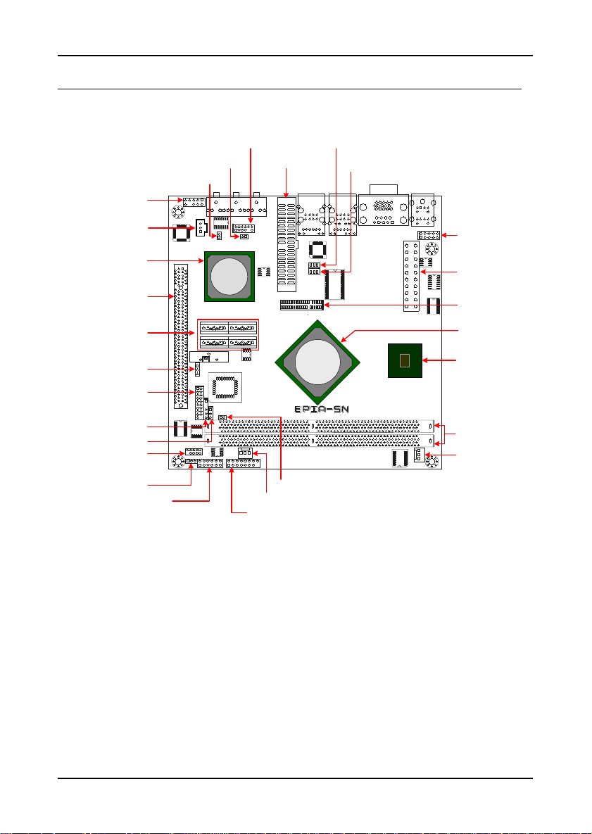
AINBOARD LAYOUT
F_AUDIO
USB 4/5
JWLESS_LED
Intruder
IDE connector
MS_CF_SEL
V_CF_SEL
SPDIF1
South Bridge
PCI Express slot
S-ATA connectors
CLEAR CMOS
JLPC1
SMBus
JCOMV2
SIR
COM2
Digital I/O
VT8251
WP
SYSFAN
Front Panel
CN896
VIA
C7 NanoBGA2
EXT_KBMS(CIR)
ATX Power slot
LVDS/DVI connector
North Bridge
NanoBGA2 CPU
DDR2 DIMM slots
CPUFAN
4
Page 15
5
Page 16
Chapter 1
B
ACK PANEL LAYOUT
6
Page 17

HAPTER
C
2
Installation
This chapter provides you with information about hardware
installation procedures. It is recommended to use a grounded wrist
strap before handling computer components. Electrostatic discharge
(ESD) can damage some components.
7
Page 18
Chapter 2
CPU
The VIA EPIA-SN Mini-ITX mainboard can support VIA C7 1.0GHz / 1.8GHz
NanoBGA2 Processor. The VIA processor C7 1.8GHz requires a heatsink with
fan to provide sufficient cooling.
VT8251
VIA
CN896
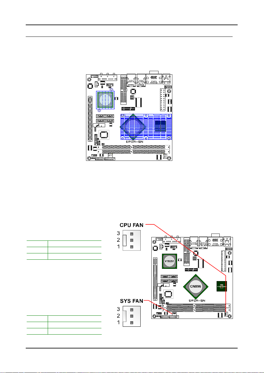
CPU Fan and System Fan: CPUFAN and SYSFAN
The CPUFAN (CPU fan) and SYSFAN (system fan) run on +12V and maintain
system cooling. When connecting the wire to the connectors, always be
aware that the red wire (positive wire) should be connected to the +12V.
The black wire is Ground and should always be connected to GND .
C7 NanoBGA2
CPUFAN
Pin Signal
1 FANIO
2 +12V
3 GND
SYSFAN
Pin Signal
1 FANIO
2 +12V
3 GND
8
Page 19
Installation
M
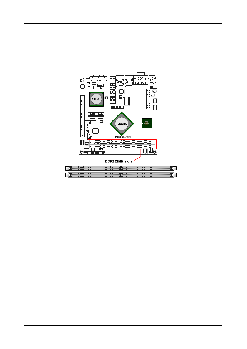
EMORY MODULE INSTALLATION
Memory Slot: DDR2 DIMM
The VIA EPIA-SN Mini-ITX mainboard provides two 240-DIMM slots for DDR2
667/533 SDRAM memory modules and supports mem ory sizes up to 4GB.
DDR2 SDRAM Module Installation Procedures
• Locate the DIMM slot in the motherboard.
• Unlock a DIMM slot by pressing the r etaining clips outward.
• Align a DIMM on the socket such that the notch on the DIMM
matches the break on the slot.
• Firmly insert the DIMM into the slot until the retaining clips snap
back in place and the DIMM is properly seated.
Available DDR2 SDRAM Configurations
Refer to the table below for available DDR2 SDRAM configurations on the
mainboard.
Slot Module Size Total
DIMM1 64MB, 128MB, 256MB, 512MB, 1GB, 2GB 64MB-2GB
DIMM2 64MB, 128MB, 256MB, 512MB, 1GB, 2GB 64MB-2GB
Maximum supported system memory 64MB-4GB
9
Page 20
Chapter 2
C
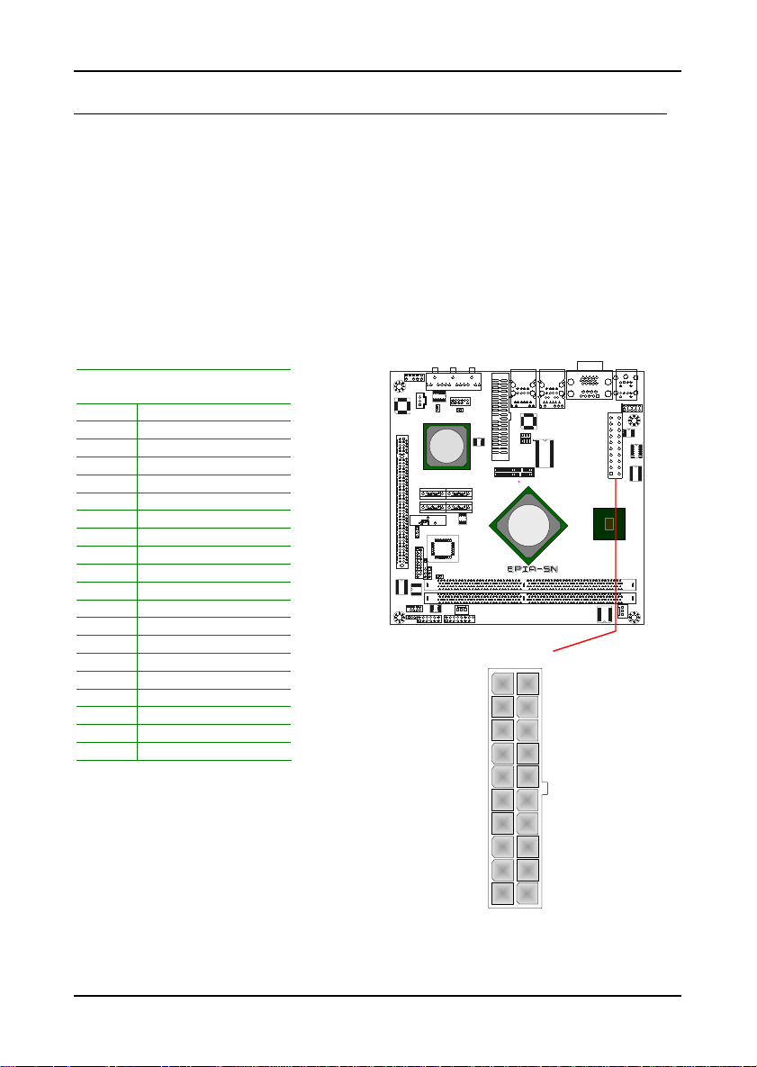
ONNECTING THE POWER SUPPLY
The VIA EPIA-SN Mini-ITX mainboard supports a conventional ATX power
supply for the power system. Before inser ting the power supply connector,
always make sure that all components are instal led correctly to ensure that
no damage will be caused.
ATX 20-Pin Power Connector
To connect the power supply, make sure the power plug is inserted in the
proper orientation and the pins are aligned. Then push down the plu g firmly
into the connector.
Pin Signal
1 +3.3V
2 +3.3V
3 GND
4 +5V
5 GND
6 +5V
7 GND
8 Power Good
9 +5V Standby
10 +12V
11 +3.3V
12 -12V
13 GND
14 Power Supply On
15 GND
16 GND
17 GND
18 -5V
19 +5V
20 +5V
VT8251
ATXPWR
10
9
8
7
6
5
4
3
2
1
CN896
20
19
18
17
16
15
14
13
12
11
VIA
C7 NanoBGA2
10
Page 21
B
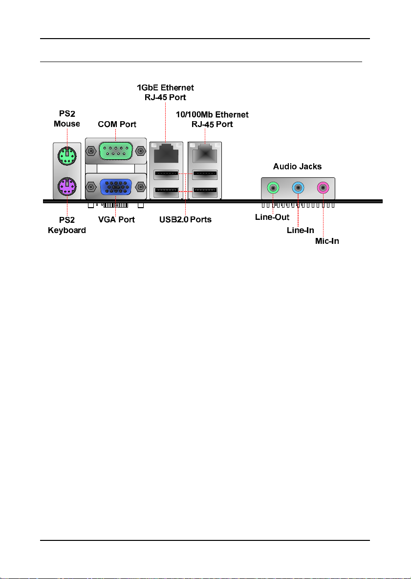
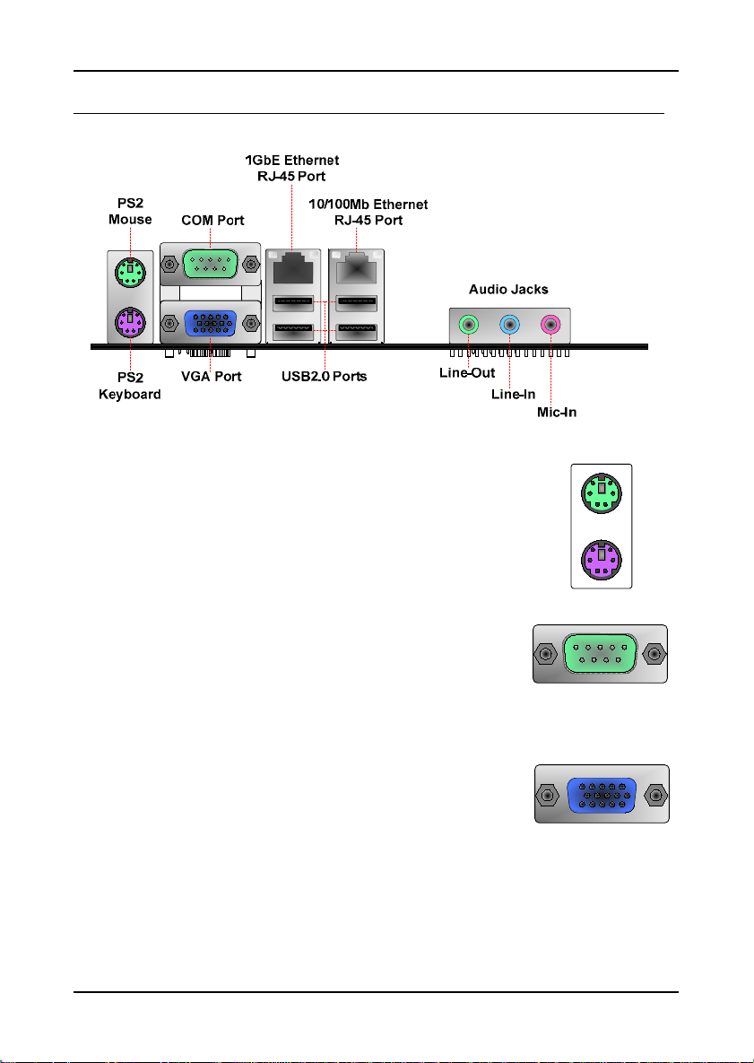
ACK PANEL PORTS
The back panel has the following port s:
Mouse and Keyboard
The connector above is for a PS/2 mouse, and the one below is
for a PS/2 keyboard.
Installation
Serial port: COM
The 9-pin COM port is for pointing devices or other serial
devices.
VGA Port
The 15-pin female VGA connector can be used to conn ect
to any analog VGA monitor.
11
Page 22
Chapter 2
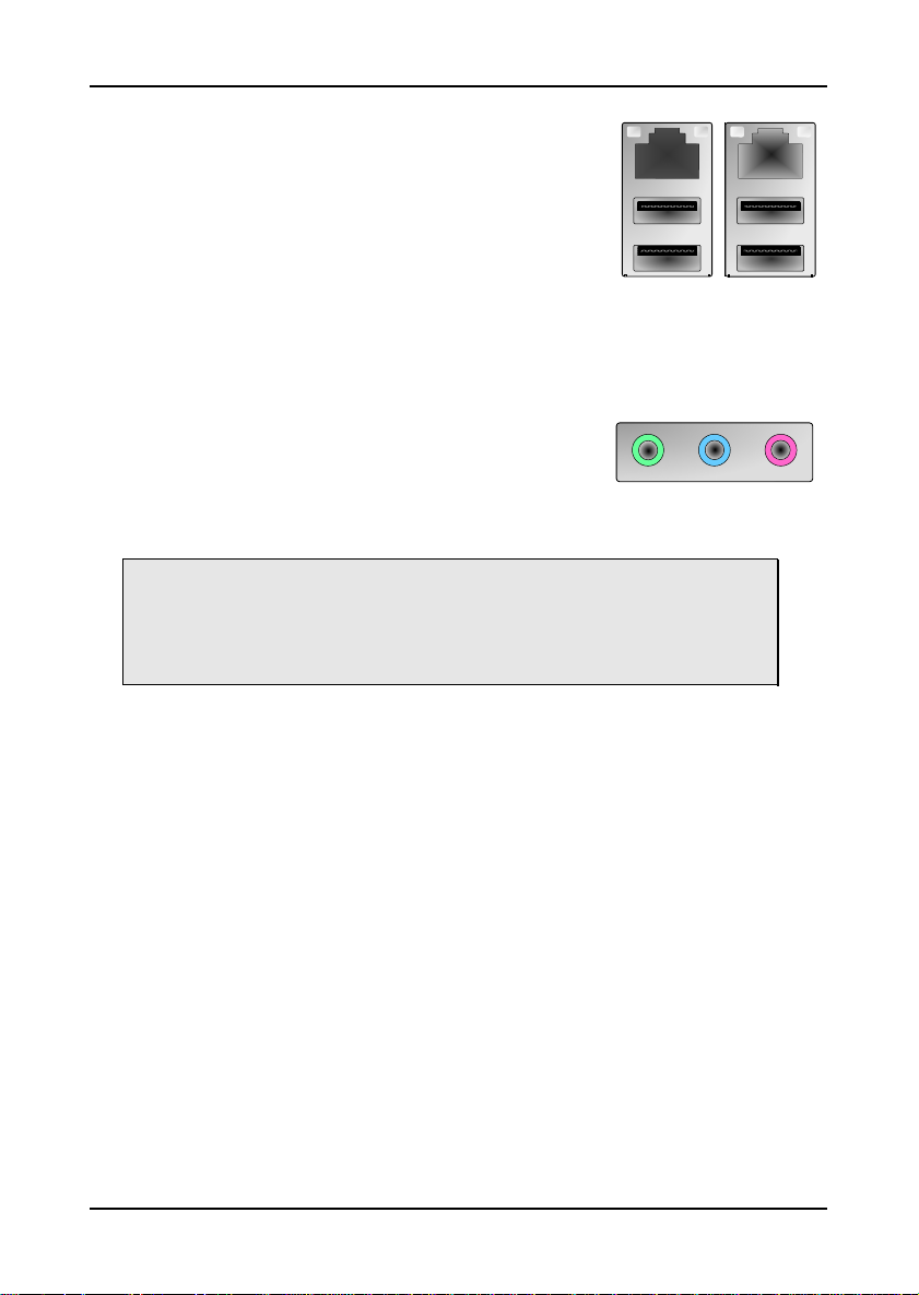
RJ45 LAN Port and USB Connectors
The mainboard provides a standard RJ-45 (10/100
Ethernet PHY and PCIe Gigabit Ethernet) and USB
2.0 ports. These ports allow connection to a Local
Area Network (LAN) through a network hub and USB
2.0 devices.
Audio Port
The Line-Out jack is for connecting to external
speakers or headphones. The Line-In jack is for
connecting to an external audio device such as a CD
player, tape player, etc. The Mic jack is for
connecting to a microphone.
Note:
The audio ports can be switched to Smart 5.1 6-channel au dio output. You
can enable the function by clicking the “Vinyl Audio” icon on your desktop after
installing the audio driver.
After completing the previou s insta llation , con nect the speakers to the 3-jack
connectors on the back panel.
12
Page 23
Installation
C
ONNECTORS
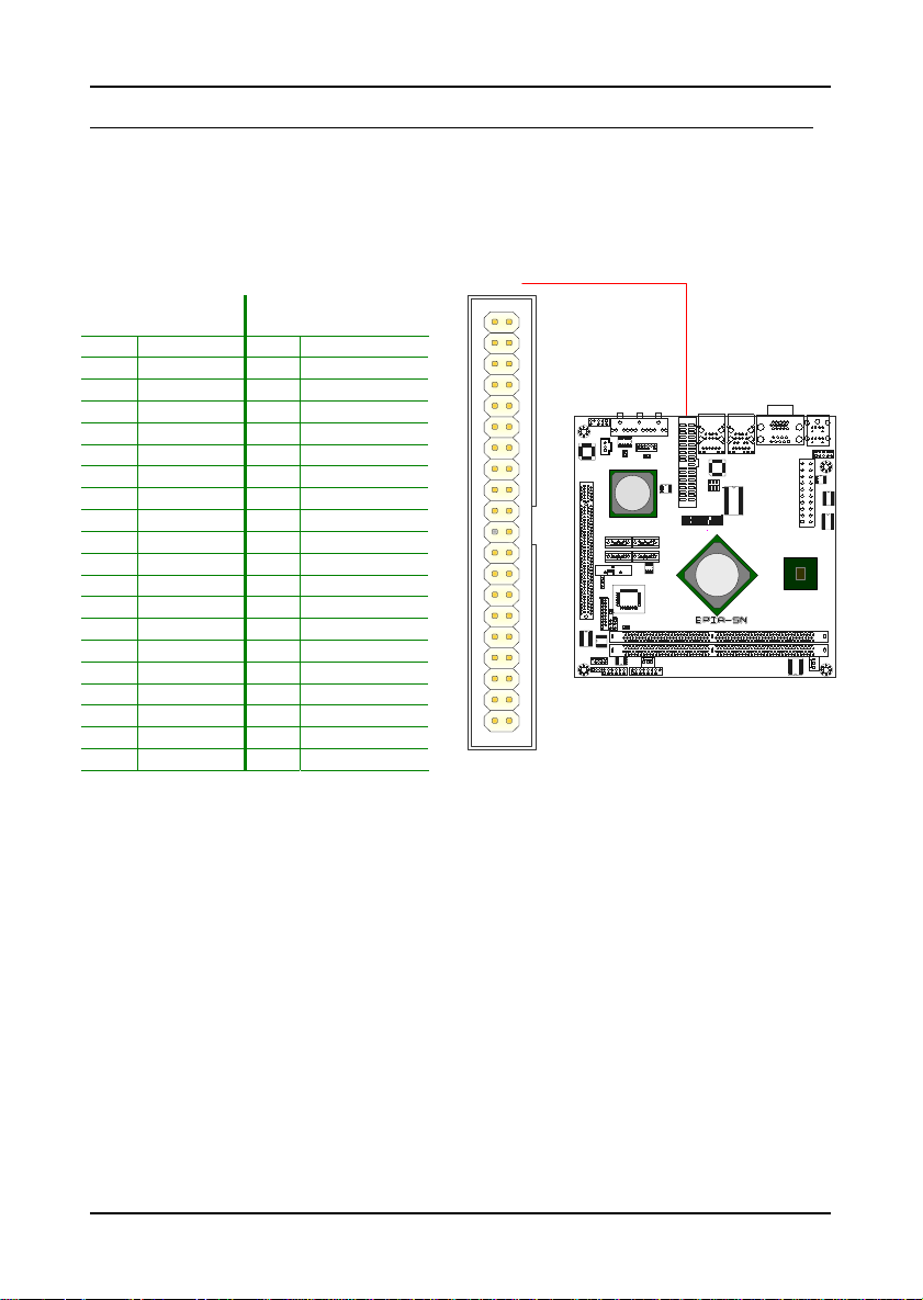
IDE Connector: IDE
The mainboard has an Ultra DMA 133/100/66 controller. You can connec t up
to two IDE devices in any combination.
Pin Signal Pin Signal
1 #IDE_RST 2 GND
3 PD_7 4 PD_8
5 PD_6 6 PD_9
7 PD_5 8 PD_10
9 PD_4 10 PD_11
11 PD_3 12 PD_12
13 PD_2 14 PD_13
15 PD_1 16 PD_14
17 PD_0 18 PD_15
19 GND 20 -21 #PD_REQ 22 GND
23 #PD_IOW 24 GND
25 #PD_IOR 26 GND
27 #PD_RDY 28 PRIMARY
29 #PD_ACK 30 GND
31 PD_IRQ15 32 -33 PD_A1 34 IDE_DMADET
35 PD_A0 36 PD_A2
37 #PD_CS1 38 #PD_CS3
IDE
38
32 31
22
10 9
3940
37
3536
3334
2930
2728
2526
2324
21
19
1718
1516
1314
1112
VT8251
VIA
CN896
78
56
34
12
C7 NanoBGA2
39 #HD_LED1 40 GND
If two drives are connected to a single ca ble, the jumper on the sec ond drive
must be set to slave mode. Refer to the d rive documentation supplied by the
vendor for the jumper settings.
13
Page 24
Chapter 2
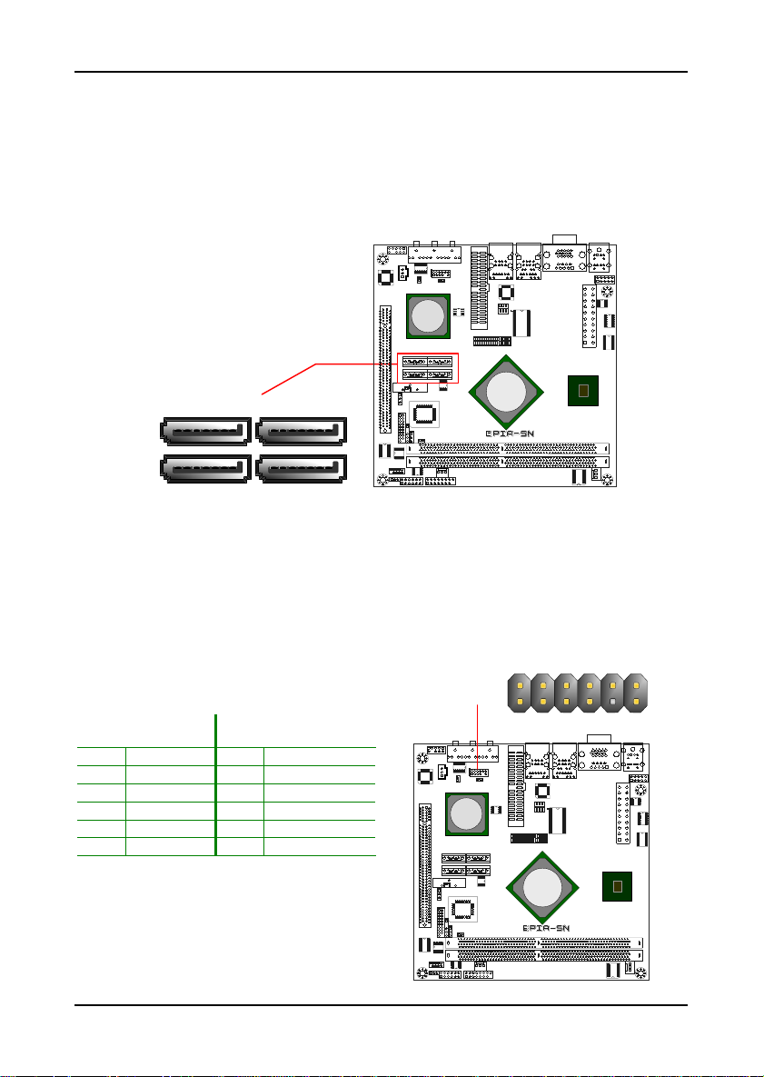
Serial ATA II Connectors: SATA1 up to SATA4
These next generation connectors suppor t the right angle Serial ATA cables
for primary internal storage devices. The current Serial ATA interface allows
up to 300MB/s data transfer rate, faster than the standard pa rallel ATA with
133 MB/s (Ultra DMA).
VT8251
VIA
SATA
CN896
24
C7 NanoBGA2
3
1
USB Pin Connector: USB
The mainboard provides 4 USB pin connectors and one USB pin header
(allowing up to 2 additional US B2.0 ports). Therefore mainboard can support
up to 6 USB2.0 ports. These p orts can be used to connect high-speed USB
interface peripherals such as USB HDD, digital cameras, MP3 players, printers,
and modems.
Pin Signal Pin Signal
1 VUSB4 2 VUSB4
3 USBD_T4- 4 USBD_T55 USBD_T4+ 6 USBD_T5+
7 GND 8 GND
9 -- 10 W_LESS-LED
11 GND 12 -RF_ON-GPO9
USB 4/5
VT8251
234
1
CN896
689101112
57
VIA
C7 NanoBGA2
14
Page 25
Installation
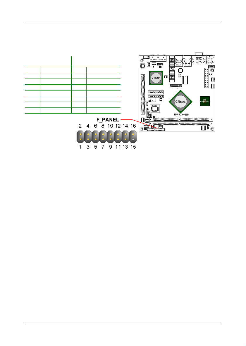
Case Connector: F_PANEL
The F_PANEL pin header allows you to connect the power swi tch, reset swit ch,
power LED, sleep LED, HDD LED and the c ase speaker .
Pin Signal Pin Signal
1 +PWR_LED 2 +HD_LED
3 +PWR_LED 4 -HD_LED
5 -PWR_LED 6 PW_BN
7 SPEAK+ 8 GND
9 -- 10 RST_SW
11 -- 12 GND
13 SPEAK- 14 +SLEEP_LED
15 Key 16 -SLEEP_LED
Power LED (PWR_LED)
The LED will light when the system is on. If the system is in S1 (POS - Power
On Suspend) or S3 (STR - Suspend To RAM) state, the LED will blink.
HDD LED (HD_LED)
HDD LED shows the activity of a hard disk drive. Avoid turn ing the p owe r off whe n
the HDD LED is still on. Connect the HDD LED from the system case to this pin.
Power Switch (PW_BN)
Connect to a 2-pin power button switch. Pressing this button will turn the
system power on or off.
Speaker (SPEAK)
The speaker from the system case is connected to this pin.
Reset Switch (RST_SW)
The reset switch is used to rebo ot the system rather than turning the power
ON/OFF. Avoid rebooting the system, if the HDD is still working. Connect
the reset switch from the system case to this pin.
Sleep LED (SLEEP_LED)
The SLEEP LED is lit when the system is in the S1 (POW-Power On Suspend)
15
Page 26
Chapter 2
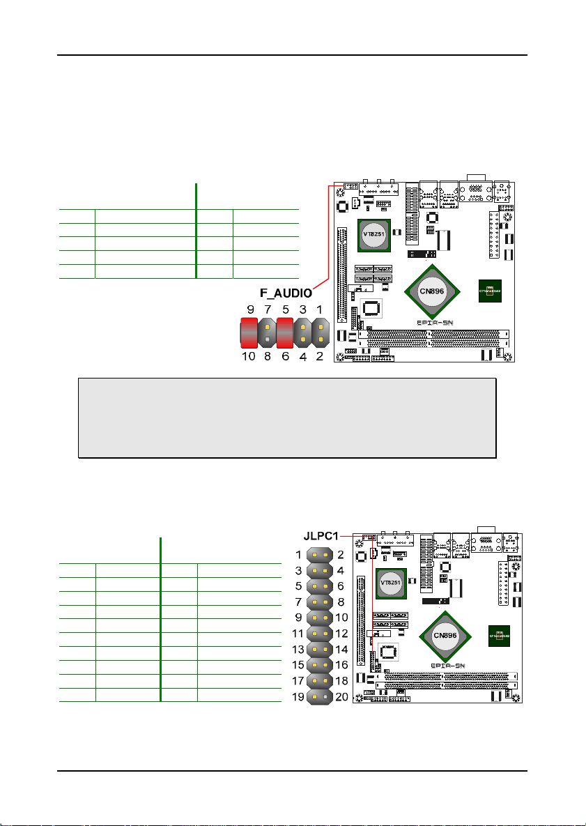
Front Panel Audio Connector: F_AUDIO
This is an interface for the VIA front panel audio cable that allow convenient
connection and control of audio devices. By default, the pins labeled
AUD_FPOUT_R and the pins AUD_FPOUT_L are shorted with jumper caps.
Remove the caps only when you are c onnectin g the front pan el audio cab le.
Pin Signal Pin Signal
1 AUD_MIC1 2 AUD_GND
3 AUD_MIC2 4 AUD_VCC
5 AUD_FPOUT_R 6 MIC2_JD
7 FRONT_IO_SENSE 8 -9 AUD_FPOUT_L 10 LIN2_JD
Note:
If you don’t want to connect to the front audio header, pins 5 & 6, 9 & 10 have
to be jumper in order to have signal output directed to the rear audio ports.
Otherwise, the Line-Out connector on the back panel will not function.
LPC Connector: JLPC1
This pin connector is for LPC devices.
Pin Signal Pin Signal
1 LAD1 2 LPCIF_33_CLK
3 -PCIRSTX 4 GND
5 LAD0 6 LPCIF_48_CLK
7 LAD2 8 -LFRAME
9 SERIRQ 10 LAD3
11 -LDRQ1 12 -EXTSMI
13 +5V 14 +3.3V
15 +5V 16 +3.3V
17 GND 18 GND
19 GND 20 --
16
Page 27
Installation
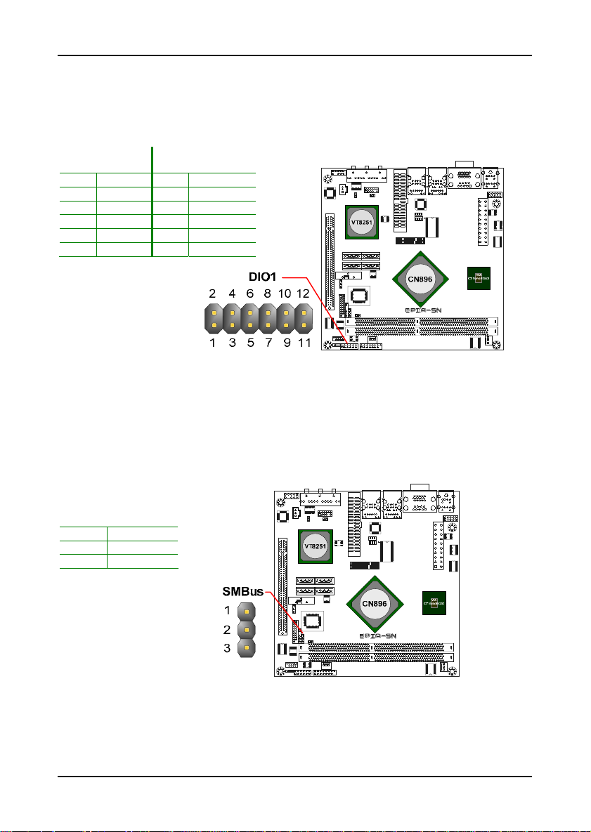
Digital I/O Connector: DIO1
General purpose input and output for POS systems.
Pin Signal Pin Signal
1 5V_DIO 2 12V_DIO
3 GPO_1 4 GPI_12
5 GPO_4 6 GPI_13
7 GPO_6 8 GPI_14
9 GPO_7 10 GPI_8
11 GND 12 GND
System Management Bus Connector: SMBus
This pin header allows you to connect SMBus (System Management Bus)
devices. Devices communicate with a SMBus host and/or other SMBus
devices using the SMBus interface
.
Pin Signal
1 SMBCK
2 SMBDT
3 GND
17
Page 28
Chapter 2
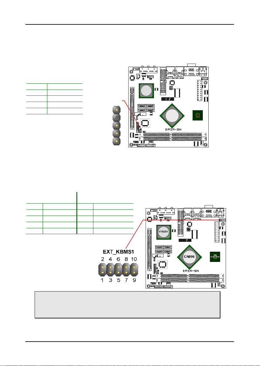
Fast IrDA Infrared Module Connector: SIR
This pin header is used to connect to an IrDA module. The BIOS settings
must be configured to activate the IR function .
Pin Signal
1 +5V
2 -3 IRRX
4 GND
5 IRTX
SIR
1
3
VT8251
CN896
VIA
C7 NanoBGA2
4
5
KBMS (or CIR) Connector: EXT_KBMS1
The mainboard provides a PS2 pin header to attach a PS2 keyboard and
mouse.
Pin Signal Pin Signal
1 +5V 2 GND
3 KB_CLK 4 KB_DATA
5 EXT_KBCLK 6 EXT_KBDATA
7 MS_CLK 8 MS_DATA
9 EXT_MSCLK 10 EXT_MSDATA
Note:
When the pin header is not in use. Pl ease short pi n 3&5, pin 4& 6, pin 7&9 and
pin 8&10.
18
Page 29

Installation
Serial Port Connector: COM2
COM2 pin header can be used to attach additional port for serial mouse or
other serial devices.
Pin Signal Pin Signal
1 DCD 2 RXD
3 TXD 4 DTR
5 GND 6 DSR
7 RTS 8 CTS
9 RI 10 --
Digital Audio Connector: SPDIF1
This connector is for connecting the Sony Philips Digital Interface (S/PDIF)
bracket. The S/PDIF output provides digital audio to external speakers or
compressed AC3 data to an external Dolby Digital Decoder. The feature is
available only with stereo system that has digital output funct ion.
Pin Signal
1 +5V
2 SPDIF_OOT
3 GND
19
Page 30

Chapter 2
LVDS/DVI Panel Connector: J2
This connector works the interface to multi display devices. An additional
daughter cards is required for a certain display support. Daughter cards for
LVDS and DVI are currently available respectively.
Pin Signal Pin Signal
1 +12V 2 +5V
3 +12V 4 +5V
5 +12V 6 +5V
7 GND 8 GND
9 +3.3V 10 GND
11 +3.3V 12 -13 -- 14 DVP2D1
15 DVP2D0 16 DVP2D3
17 DVP2D2 18 DVP2D5
19 DVP2D4 20 GND
21 GND 22 DVP2D9
23 DVP2D6 24 DVP2D7
25 DVP2D8 26 DVP2D11
27 DVP2D10 28 GND
29 GND 30 DVP2CLK
31 DVP2DE 32 GND
33 DVP2VS 34 ENVDD-2
35 DVP2HS 36 ENVBLD-2
37 GND 38 -PCIRSTX
39 SPD1 40 SPCLK1
20
Page 31

Installation
J
UMPERS
The mainboard provides jumper s for setting some mainboard functions. This
section will explain how to change the settings of the mainboard functions
using the jumpers.
Clear CMOS Connector: CLEAR_CMOS
The onboard CMOS RAM stores system configuration data and has an
onboard battery power supply. To reset the CMOS settings, set the jumper
on pins 1 and 2 while the system is off. Return th e jumper to pins 2 and 3
afterwards. Setting the jumper while the system is on will damage the
mainboard.
Setting 1 2 3
Normal Operation ON ON OFF
Clear CMOS setting OFF ON ON
Warning:
Except when clearing the R TC RAM, never remove t he cap on CLEAR_CM OS
jumper default position. Removing the cap will cause system boot failure.
Avoid clearing the CMOS while the system is on; it will damage the mainboard.
21
Page 32

Chapter 2
MS_CF_SEL
This jumper determines the working st ate of the CF connector. The default
value is Master.
Setting 1 2 3
Slave ON ON OFF
Master OFF ON ON
Voltage Selector for the CF Connector: V_CF_SEL
This VCC selector jumper is to determine the input voltage of the CF
connector. The default value is +3.3V.
Setting 1 2 3
+3.3V ON ON OFF
+5V OFF ON ON
+3.3V
+5V
V_CF_SEL
21 3
21 3
22
VT8251
CN896
VIA
C7 NanoBGA2
Page 33

Installation
Voltage Selector for COM Connectors: JCOMV2
This VCC selector is to determine the inpu t voltage of ea ch COM connect or.
Setting 1 2 3
+5V ON ON OFF
+12V OFF ON ON
ROM Write Protection: WP
This jumper allows you to protect from flashing the BIOS. ROM Write
Protection setting: pin1 = WP#, pin2 = GND, short 1-2.
23
Page 34

Chapter 2
INTRUDER
This pin connector is for chassis intrus ion switch c onnector. Thi s is no t
a default function supported by BIOS .
Pin Signal
1 INTRUDER
2 GND
Wireless LED1: JWLESS-LED1
This pin connector is for th e LED indicator of VIA VT6656 wireless LAN USB
module.
Pin Signal
1 +3.3V
2 W_LESS_LED
JWLESS-LED1
12
24
VT8251
CN896
VIA
C7 NanoBGA2
Page 35

Installation
S
LOTS
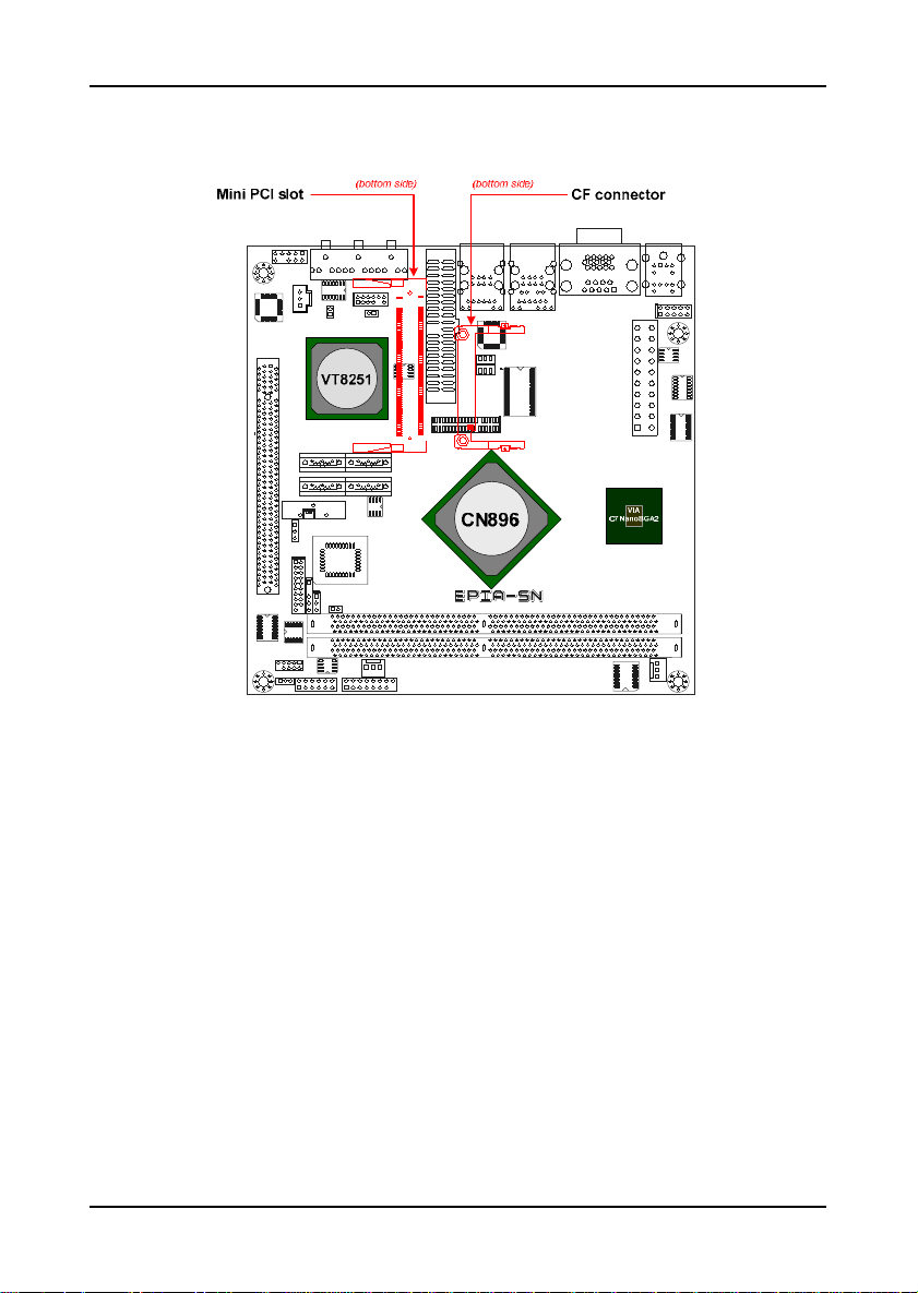
Mini Peripheral Component Interconnect: MiniPCI
The MiniPCI slot allows you to insert a MiniPCI expansion card. First unplug
the power supply before adding or removing expansion cards. Read the
documentation for the expansion card to see if any changes to the sy stem are
necessary.
PCI Interrupt Request Routing
The IRQ (interrupt request line) are hardware lines over which devices can
send interrupt signals to the microprocess or. The “PCI & LAN” IRQ pins are
typically connected to the PCI bus INT A# ~ INT D# pins as follows:
Order 1 Order 2 Order 3 Order 4
MiniPCI Slot INT B# INT C# INT D# INT A#
25
Page 36

Chapter 2
Compact Flash Type I Connector: CF
This CF connector allows you to connect to a passive 50-pin Type I adapter.
PCI Express: PCIe x16
The PCI Express slot allows you to insert a PCI Express x16 graphics
expansion card. First unplug the power supply before adding or removing
expansion cards. Read the documentation for the expansion card to see if
any changes to the system are necessary.
26
Page 37

HAPTER
C
3
BIOS Setup
This chapter gives a detailed explanation of the BIOS setup functions.
27
Page 38

Chapter 3
E
NTERING SETUP
Power on the computer and press <Delete> during the beginning of the boot
sequence to enter the BIOS setup menu. If you missed the BIOS setu p entry
point, you may restart the system and try again.
28
Page 39

C
ONTROL KEYS
Keys Description
Move to the previous item
BIOS Setup
Enter
Esc
F1
F7
F9
F10
Move to the next item
Move to the item in the left side
Move to the item in the right side
Select the item or field
Exit from sub-menu. And discard changes and exit
setup
Select the item or field
Increase the numeric value or ma ke changes
Decrease the numeric value or make chang es
General help, only for Status Page Setup Menu and
Option Page Setup Menu
Load the default CMOS value from Fail-Safe default
table
Discard all changes
Load Optimized defaults
Save all the configuration changes and exit
29
Page 40

Chapter 3
N
AVIGATING THE
The main menu displays all the BIOS setup categories. Use the Left/Right
and Up/Down arrow keys to select any item or sub-menu. Description of the
selected/highlighted category is disp layed at the bottom of the scre en.
BIOS M
ENUS
30
Page 41

BIOS Setup
An arrow symbol next to a field indicates that a sub-menu is availa ble (see
figure below). Press <Enter> to display the sub-menu. To exit the submenu, press <Esc>.
31
Page 42

Chapter 3
G
ETTING HELP
The BIOS setup program provides a “Gen eral Help” screen. You can display
this screen from any menu/sub-menu by pressing <F1>. The help screen
displays the keys for using and navigating the BIOS setup. Press <Esc> to
exit from sub-menu, and discard changes and exit setup.
32
Page 43

BIOS Setup
M
AIN MENU
The Main Menu contains six setup functions and one exit choice. Use the
“left/right” arrow keys to select the main menu categories and press the
“up/down” arrow keys to select items. Press “Enter” to accept or enter a submenu.
Main Advanced PCIPnP Boot
System Overview
AMIBIOS
Version : 001 (TEST)
Build Date : 08/08/07
ID : 1ADTQ001
Processor
VIA C7 Processor 1000MHz
Speed : 1000MHz
Count : 1
System Memory
Size : 256MB
System Memory [ 16: 22:03 ]
System Date [ Wed 08/08/2007 ]
BIOS SETUP UTILITY
Security Chipset Exit
Use [ENTER], [TAB]
or [SHIFT-TAB] to
select a field.
Use [+] or [-] to
configure system
Time.
Select Screen
Select Item
Change Field
+-
Select FieldTab
General Help
F1
Save and Exit
F10
Exit
ESC
v02.61 (C) Copyright 1985-2006, American Megatrends, Inc.
Main (System O ve rview)
Use this menu to set basic system configurations.
Advanced (Advanced Settings)
Use this menu to configure your system and set the advanced BIOS features.
PCIPnP (Advanced PCI/PnP Settings)
Use this menu to set the PCI and PnP configurations.
Boot (Boot Settings)
Use this menu to set the boot se tting c onfigurati on and device priori ty.
Security (Security Settings)
Use this menu to configure the se curity f eatures .
33
Page 44

Chapter 3
Chipset (Advanced Chipset Settings)
Use this menu to set specific chipset feature and optimize system
performance.
Exit (Exit Options)
Use this menu option to load BIOS default setting, save BIOS setting changes,
discard BIOS setting changes and e xit se tup.
34
Page 45

M
AIN (SYSTEM OVERVIEW
)
Main Advanced PCIPnP Boot
System Overview
AMIBIOS
Version : 001 (TEST)
Build Date : 08/08/07
ID : 1ADTQ001
Processor
VIA C7 Processor 1000MHz
Speed : 1000MHz
Count : 1
System Memory
Size : 256MB
System Memory [ 16: 22:03 ]
System Date [ Fri 08/08/2007 ]
BIOS SETUP UTILITY
Security Chipset Exit
Use [ENTER], [TAB]
or [SHIFT-TAB] to
select a field.
Use [+] or [-] to
configure system
Time.
Select Screen
Select Item
Change Field
+-
Select FieldTab
General Help
F1
Save and Exit
F10
Exit
ESC
BIOS Setup
v02.61 (C) Copyright 1985-2006, American Megatrends, Inc.
AMIBIOS
Show the BIOS version, build date and ID.
Processor
Show the total number, type, speed of V IA process or used in the sy stem.
System Memory
Total memory size used in the system.
System Time
The time format is [Hour : Minute : Secon d]
System Date
The date format is [Day, Month : Date Year]
35
Page 46

Chapter 3
A
DVANCED (ADVANCED SETTINGS
Main Advanced PCIPnP Boot
Advanced Settings
WARNING: Setting wrong values in below sections may
cause system to malfunction.
CPU Configuration
IDE Configuration
Super IO Configuration
Hardware Health Configuration
ACPI Configuration
APM Configuration
PCI Express Configuration
Remote Access Configuration
Trusted Computing
USB Configuration
BIOS SETUP UTILITY
)
Security Chipset Exit
Configure CPU.
Select Screen
Select Item
Go to Sub Screen
Enter
General Help
F1
Save and Exit
F10
Exit
ESC
v02.61 (C) Copyright 1985-2006, American Megatrends, Inc.
CPU Configuration
Configure the processor.
IDE Configuration
Configure the IDE (Integra ted Drive Electr onics ) devi ces.
Super IO Configuration
Configure Super IO chipset.
Hardware Health Configuration
Configure/monitor the hardware health.
ACPI Configuration
Section for Advanced ACPI Configuration.
APM Configuration
Section for Advanced Power Management (AMP) Configuration.
PCI Express Configuration
Configure PCI Express.
36
Page 47

Remote Access Configuration
Configure Remote Access.
Trusted Computing
Configure settings related to Trusted Computing innovations.
USB Configuration
Configure USB (Universal Serial Bus) supports.
BIOS Setup
37
Page 48

Chapter 3
CPU C
ONFIGURATION
Advanced
Configure advanced CPU settings
Module Version : 3F.00
Manufacturer : VIA
VIA C7 Processor 1000 MHz
Frequency : 1.00 GHz
FSB Speed : 400 MHz
Cache L1 : 128 KB
Cache L2 : 128 KB
Ratio Actual Value : 10
CMPXCHG8B instruction support [ Enabled ]
v02.61 (C) Copyright 1985-2006, American Megatrends, Inc.
BIOS SETUP UTILITY
If you want to install
Windows NT 4.0 you must
disable it.
Select Screen
Select Item
Change Option
+-
General Help
F1
Save and Exit
F10
Exit
ESC
Items Description
Manufacturer The name of company manufacturer:
VIA C7 Processor 1000MHz Type of Processor used:
Frequency Processor speed: 1GHz
FSB Speed Front Side Bus speed: 400MHz
Cache L1 Processor Level 1 Cache
Cached L2 Processor Level 2 Cache
Ratio Actual Value
CMPXCHG8B instruction support
VIA Technologies Inc.
VIA C7 1GHz
38
Page 49

BIOS Setup
IDE C
ONFIGURATION
Advanced
IDE Configuration
Parallel ATA IDE devices
Primary IDE Master [ Not Detected ]
Primary IDE Slave [ Not Detected ]
SATA Controller [ RAID ]
SATA Option ROM [ Enabled ]
Hard Disk Write Protect [ Disabled ]
IDE Detect Time Out (Sec) [ 35 ]
ATA(PI) 80 Pin Cable Detection [ Host ]
v02.61 (C) Copyright 1985-2006, American Megatrends, Inc.
BIOS SETUP UTILITY
IDE
RAID
AHCI
Enter
F1
F10
ESC
Options
Select Screen
Select Item
Go to Sub Screen
General Help
Save and Exit
Exit
SATA Controller
Controls the features of the Serial ATA controller within the South Bridge.
Serial ATA is the latest generation of the ATA interface. Serial ATA hard
drives deliver transfer speeds of up to 300MB/se c.
Setting Description
IDE Supports two PATA hard disk drives. Disables RAID and AHCI
RAID Only SATA supports RAID and AHCI function
AHCI Enable the AHCI function such as Native Command Queuing and
function.
Hot Plug function
SATA Option ROM
Settings: [Disabled Enabled]
Hard Disk Write Protect
Protects the hard disk from copying and writin g.
Settings: [Disabled, Enabled]
39
Page 50

Chapter 3
IDE Detect Time Out (Sec)
Sets the time for the BIOS to dela y the initia lization of IDE device s. It enable s
IDE devices to have more time to spin up before being initialized by th e BIOS.
Settings: [0, 5, 10, 15, 20, 25, 30, 3 5]
Note:
Set it to default value 0 if you are not using old IDE devices.
ATA(PI) 80 Pin Cable Detection
This feature allows the IDE controller and IDE device to detect the type of
IDE cable that is being used.
Setting Description
Host & Dev ic e IDE controller and IDE device will detect the types of IDE cable used.
Host IDE controller will detect the types of IDE cable used.
Device IDE device will detect the types of IDE cable used.
40
Page 51

P
RIMARY
IDE M
ASTER /
Advanced
Primary IDE Master
Device : Not Detected
Type [ Auto ]
LBA/Large Mode [ Auto ]
Block (Multi-Sector Transfer) [ Auto ]
PIO Mode [ Auto ]
DMA Mode [ Auto ]
S.M.A.R.T. [ Auto ]
32Bit Data Transfer [ Enabled ]
IDE S
BIOS SETUP UTILITY
LAVE
BIOS Setup
Select the type of the
device connected to
the system.
Select Screen
Select Item
Change Option
+-
General Help
F1
Save and Exit
F10
Exit
ESC
v02.61 (C) Copyright 1985-2006, American Megatrends, Inc.
Type
This setting use to select the type of Primary Master IDE drive c onnected to
the system. Select “Auto” to detect IDE drives automatically.
Settings: [Not Installed, Auto, CD/DVD, ARMD]
LBA/Large Mode
This setting allows to disable or ena ble(Auto) t he LBA ca pacity.
Setting Description
Disabled Disables LBA Mode
Auto Enables LBA Mode if the device supports it and the device is not
already formatted with LBA Mode disabled.
Block (Multi-Sector Transfer)
This setting allows you to set the numbers of sectors.
Setting Description
Disabled The data transfer from and to the device occurs one sector at a time.
Auto The data transfer from and to the device occurs multiple sectors at a
time if the device supports it.
41
Page 52

Chapter 3
PIO Mode
Set Programmed Input/Output Mode for th e Master ID E drive.
Setting Description
Auto Auto-detect the maximum PIO mode supported by the IDE drives.
0 Use PIO mode 0 for the IDE drive
1 Use PIO mode 1 for the IDE drive
2 Use PIO mode 2 for the IDE drive
3 Use PIO mode 3 for the IDE drive
4 Use PIO mode 4 for the IDE drive
Note:
Normal setting should be s et to “ Auto.” To auto -detect the ma ximum su pported
PIO mode.
DMA Mode
This setting use to select the Di rect Mem ory Acce ss (DMA) mo de.
Setting Description
Auto Auto detect
SWDMAn SingleWordDMAn
MWDMAn MultiWordDMAn
UDMan UltraDMAn
S.M.A.R.T.
This feature enables or disables the Self-Monitoring Analysis and Reporting
Technology (S.M.A.R.T.). The S.M.A.R.T technology main function is to
monitor the storage devices (hard disk drives) health and status. It enables a
report for the possible problem and predicts future failure of storage devices.
Settings: [Auto, Disabled, Enabled]
Note:
Normally set to “Disabled”, to avoid decrease of system performance.
42
Page 53

BIOS Setup
32 Bit Data Transfer
Enabling this setting allows for 32-bit data transfers between the processor
and the PCI bus.
Settings: [Disabled, Enabled]
Note:
Recommend set to “Enabled”, to increase of system performance.
43
Page 54

Chapter 3
S
UPER IO CONFIGURATION
Advanced
Configuration SCH3112 Super IO Chipset
Serial Port1 Address [ 3F8 ]
Serial Port1 IRQ [ 3 ]
Serial Port2 Address [ 2F8 ]
Serial Port2 IRQ [ 3 ]
WATCH-DOG [ Disabled ]
BIOS SETUP UTILITY
Allows BIOS to Select
Serial Port1 Base
Addresses.
Select Screen
Select Item
Change Option
+-
General Help
F1
Save and Exit
F10
Exit
ESC
v02.61 (C) Copyright 1985-2006, American Megatrends, Inc.
Configure SCH3112 Super I/O Chipset
Items Description
Serial Port 1 Address Sets the base I/ O port 1 address for the onboard serial port.
Serial Port 1 IRQ Sets the base I/O port 1 IRQ for the onboard serial port.
Serial Port 2 Address Sets the base I/ O port 2 address for the onboar d serial port.
Serial Port 2 IRQ Sets the base I/O port 2 IRQ for the onboard serial port.
Watch-Dog Allows BIOS to select Watch-Dog support.
Settings: [Disabled, 3F8, 3E8, 2E8]
Settings: [3, 4, 10, 11]
Settings:[2F8, 3E8, 2E8]
Settings: [3, 4, 10, 11]
Settings: [Disabled, E nabled ]
44
Page 55

H
ARDWARE HEALTH CONFIGURATION
Advanced
Hardware Health Configuration
H/W Health Function [ Enabled ]
PWM 1 Mode Setting [ Fan Always On Full ]
PWM 1 Ramp Rate [ 4.85 Hz ]
PWM 2 Mode Setting [ Fan Always On Full ]
PWM 2 Ramp Rate [ 4.85 Hz ]
System-Fan (1) Speed : N/A
CPU-Fan (2) Speed : N/A
Vcore : 0.992 V
+3.3Vin : 3.282 V
+5Vin : 4.974 V
+12Vin : 12.048 V
BIOS SETUP UTILITY
Enables Hardware
Health Monitoring
Device.
Select Screen
Select Item
Change Option
+-
General Help
F1
Save and Exit
F10
Exit
ESC
BIOS Setup
v02.61 (C) Copyright 1985-2006, American Megatrends, Inc.
The PC Health Status displays the current status of all of the monitored
hardware devices/components such as CPU voltages, temperatures and fan
speeds.
Items Description
H/W Health Function Enables Hardware Health Monitoring Device.
PWM 1 Mode Setting PWM Configuration Mode Setting.
PWM 1 Ramp Rate If enable, limits the amount of change in the PWM duty cycle
PWM 2 Mode Setting PWM Configuration Mode Setting.
PWM 2 Ramp Rate If enable, limits the amount of change in the PWM duty cycle
Settings: [Disabled, E nabled ]
Settings: [Auto Fan Mode, Fan Always On Fu ll, Fan Disab le
Mode, fan Manually Mode]
over a specified period of time.
Settings: [4.85Hz, 9.62Hz, 14.49Hz, 24.39Hz, 3 8.46Hz,
55.56Hz, 100Hz, 200Hz]
Settings: [Auto Fan Mode, Fan Always On Fu ll, Fan Disab le
Mode, fan Manually Mode]
over a specified period of time.
Settings: [4.85Hz, 9.62Hz, 14.49Hz, 24.39Hz, 3 8.46Hz,
55.56Hz, 100Hz, 200Hz]
45
Page 56

Chapter 3
ACPI C
ONFIGURATION
Advanced
ACPI Settings
General ACPI Configuration
Advanced ACPI Configuration
Chipset Configuration
v02.61 (C) Copyright 1985-2006, American Megatrends, Inc.
BIOS SETUP UTILITY
General ACPI
Configuration settings
Select Screen
Select Item
Go to Sub Screen
Enter
General Help
F1
Save and Exit
F10
Exit
ESC
General ACPI Configuration
General Advanced Configuration and Power Interface (ACPI) configuration
setting and power management.
Advanced ACPI Configuration
Advanced configuration setting. Use this section to configure additional ACPI
option.
Chipset Configuration
Chipset Advanced Configuration and Power Interfa ce (ACPI) related
configuration settings.
46
Page 57

G
ENERAL
ACPI C
Advanced
General ACPI Configuration
Suspend mode [ Auto ]
Repost Video on S3 Resume [ No ]
ONFIGURATION
BIOS SETUP UTILITY
BIOS Setup
Select the ACPI
state used for
System Suspend.
Select Screen
Select Item
Change Option
+-
General Help
F1
Save and Exit
F10
Exit
ESC
v02.61 (C) Copyright 1985-2006, American Megatrends, Inc.
Suspend Type
Select the ACPI state used for System Suspend.
Setting Description
S1(POS) S1/Power On Suspend (POS) is a low power state. In this state,
S3(STR) S3/Suspend To RAM (STR) is a power-down state. In this state,
Auto Depend on the OS to select S1 or S3.
no system context (CPU or chipset) is lost and hardware
maintains all system con texts.
power is supplied only to essential components such as main
memory and wakeup-capable devices. The system context is
saved to main memory, and context is restored from the
memory when a "wakeup" event occurs.
Repost Video on S3 Resume
Select whether to run VGA BIOS if resuming from S3 state.
Settings: [No, Yes]
47
Page 58

Chapter 3
A
DVANCED
ACPI C
ONFIGURATION
Advanced
Advanced ACPI Configuration
ACPI Version Features [ ACPI v1.0 ]
ACPI APIC support [ Enabled ]
AMI OEMB table [ Enabled ]
Headless mode [ Disabled ]
BIOS SETUP UTILITY
Enable RSDP pointers
to 64-bit Fixed System
Description Tables.
Select Screen
Select Item
Change Option
+-
General Help
F1
Save and Exit
F10
Exit
ESC
v02.61 (C) Copyright 1985-2006, American Megatrends, Inc.
ACPI Version Features
Enable RSDP pointers to 64-bit Fixed Sys tem Desc ription Tabl es.
Settings: [ACPI v1.0, ACPI v2.0, ACPI v3.0 ]
ACPI APIC Features
Include ACPI APIC table pointer to RSDT pointer lis t.
Settings: [Disabled, Enabled]
AMI OEMB Table
Include OEMB table pointer to R(X)SDT pointer lists.
Settings: [Disabled, Enabled]
Headless Mode
Headless operation mode through ACPI.
Settings: [Disabled, Enabled]
48
Page 59

C
HIPSET
ACPI C
ONFIGURATION
Advanced
USB Device Wakeup Function [ Enabled ]
BIOS SETUP UTILITY
Disabled
Enabled
+F1
F10
ESC
Options
Select Screen
Select Item
Change Option
General Help
Save and Exit
Exit
BIOS Setup
v02.61 (C) Copyright 1985-2006, American Megatrends, Inc.
USB Device Wakeup Function
Settings: [Disabled, Enabled]
49
Page 60

Chapter 3
APM C
ONFIGURATION
Advanced
Power Management/APM [ Enabled ]
Power Button Mode [ On/Off ]
Suspend Power Saving Type [ C3 ]
Restore on AC/Power Loss [ Last State ]
Standby Time Out [ Disabled ]
Suspend Time Out [ Disabled ]
Hard Disk Time Out (Minute) [ Disabled ]
Green PC Monitor Power State [ Suspend ]
Video Power Down Mode [ Suspend ]
Hard Disk Power Down Mode [ Suspend ]
Advanced Monitor Events Controls
Display Activity [ Ignore ]
Monitor IRQ3 [ Monitor ]
Monitor IRQ4 [ Ignore ]
Monitor IRQ5 [ Ignore ]
Monitor IRQ7 [ Ignore ]
Monitor IRQ9 [ Ignore ]
Monitor IRQ10 [ Ignore ]
Monitor IRQ11 [ Ignore ]
Monitor IRQ13 [ Ignore ]
Monitor IRQ14 [ Monitor ]
Monitor IRQ15 [ Ignore ]
Advanced Resume Events Controls
Resume On Ring [ Disabled ]
Resume On LAN [ Disabled ]
Resume On PME# [ Disabled ]
Resume On KBC [ Disabled ]
Wake-Up Key [ Any Key ]
Resume On PS/2 Mouse [ Disabled ]
Resume On RTC Alarm [ Disabled ]
v02.61 (C) Copyright 1985-2006, American Megatrends, Inc.
BIOS SETUP UTILITY
Disabled
Enabled
+F1
F10
ESC
Options
Select Screen
Select Item
Change Option
General Help
Save and Exit
Exit
Power Management/APM
Settings: [Disabled, Enabled]
Power Button Mode
Settings: [On/Off, Standby, Suspend]
Suspend Power Saving Type
Settings: [C3, S1]
Restore on AC/Power Loss
Settings: [Power Off, Power On, Last State]
50
Page 61

BIOS Setup
Standby Time Out
Settings: [Disabled, 1 Min, 2 Min, 4 M in, 8 Min, 10 Min, 20 Min, 30 M in, 40
Min, 50 Min, 60 Min]
Suspend Time Out
Settings: [Disabled, 1 Min, 2 Min, 4 M in, 8 Min, 10 Min, 20 Min, 30 M in, 40
Min, 50 Min, 60 Min]
Hard Disk Time Out (Minute)
Settings: [1, 2, 3, 4, 5, 6, 7, 8, 9, 10, 11, 12, 13, 14, 15]
Green PC Monitor Power State
Settings: [Standby, Suspend, Off]
Video Power Down Mode
Settings: [Disabled, Standby, Suspend]
Hard Disk Power Down Mode
Settings: [Disabled, Standby, Suspend]
Advanced Monitor Events Controls
Items Description
Display Activity Settings: [Ignore, Monitor]
Monitor IRQ3 Settings: [Ignore, Monitor]
Monitor IRQ4 Settings: [Ignore, Monitor]
Monitor IRQ5 Settings: [Ignore, Monitor]
Monitor IRQ7 Settings: [Ignore, Monitor]
Monitor IRQ9 Settings: [Ignore, Monitor]
Monitor IRQ10 Settings: [Ignore, Monitor]
Monitor IRQ11 Settings: [Ignore, Monitor]
Monitor IRQ13 Settings: [Ignore, Monitor]
Monitor IRQ14 Settings: [Ignore, Monitor]
Monitor IRQ15 Settings: [Ignore, Monitor]
51
Page 62

Chapter 3
Advanced Resume Events Controls
Items Description
Resume On Ring Settings: [Disabled, E nabled ]
Resume On LAN Settings: [Disabled, Enabled]
Resume On PME# Sett ings: [D isabled , Enabled ]
Resume On KBC Settings: [Disabled S3, S3/S4 /S5]
Wake Up Key Settings: [Any Key]
Resume On PS/2 Mouse Settings: [Disab led, Enab led]
Resume On RTC Alarm Settings: [Disabled, Enabled]
52
Page 63

BIOS Setup
PCI E
XPRESS CONFIGURATION
Advanced
PCI Express Configuration
Activate State Power-Management [ Disabled ]
PCIE-NB Configuration
v02.61 (C) Copyright 1985-2006, American Megatrends, Inc.
BIOS SETUP UTILITY
Enable/Disable
PCI Express L0s
and L1 link power
states.
+F1
F10
ESC
Activate State Power-Management
Enable/Disable PCI Express L0s and L1 link power states.
Settings: [Disabled, Enabled]
Select Screen
Select Item
Change Option
General Help
Save and Exit
Exit
53
Page 64

Chapter 3
PCI-NB C
ONFIGURATION
Advanced
PCIE-NB Configuration
PEG Control [ Normal ]
PEG Link [ Default ]
PE0 Control [ Normal ]
PE0 Link [ Default ]
Reset PCIE When Link Fail [ Enabled ]
v02.61 (C) Copyright 1985-2006, American Megatrends, Inc.
BIOS SETUP UTILITY
Options
Normal
Link Disabled
PHY LS LoopBack
PHY ES LoopBack
Select Screen
Select Item
Change Option
+-
General Help
F1
Save and Exit
F10
Exit
ESC
PEG Control
Settings: [Normal, Link Disabled, PHY LS LoopBack, PHY ES LoopBack]
PEG Link
A feature allows you to change the PCI Express x16 mode to othe r mode.
Settings: [x1, x2, x4, x8, x16]
PE0 Control
Settings: [Normal, Link Disabled, PHY LS LoopBack, PHY ES LoopBack]
PE0 Link
Settings: [Default, x1, x2, x4]
Reset PCIE When Link Fail
Settings: [Disabled, Enabled]
54
Page 65

R
EMOTE ACCESS CONFIGURATION
Advanced
Configure Remote Access type and parameters
Remote Access [ Disabled ]
BIOS SETUP UTILITY
BIOS Setup
Select Remote Access
type.
Select Screen
Select Item
Change Option
+-
General Help
F1
Save and Exit
F10
Exit
ESC
v02.61 (C) Copyright 1985-2006, American Megatrends, Inc.
Remote Access
Configure Remote Access type and pa ramet ers.
Settings: [Disabled, Enabled]
55
Page 66

Chapter 3
T
RUSTED COMPUTING
Advanced
Trusted Computing
TCG/TPM SUPPORT [ No ]
BIOS SETUP UTILITY
Enable/Disable TPM
TCG (TPM 1.1/1.2)
Select Screen
Select Item
Change Option
+-
General Help
F1
Save and Exit
F10
Exit
ESC
v02.61 (C) Copyright 1985-2006, American Megatrends, Inc.
TCG/TPM Support
Settings: [No, Yes]
56
Page 67

BIOS Setup
USB C
ONFIGURATION
Advanced
USB Configuration
Module Version – 2.24.2-13.4
USB Devices Enabled :
USB 1.1 Ports Configuration [ USB 6 Ports ]
USB 2.0 Ports Enable [ Enabled ]
Legacy USB Support [ Enabled ]
Port 64/60 Emulation [ Disabled ]
USB 2.0 Controller Mode [ HiSpeed ]
BIOS EHCI Hand-Off [ Enabled ]
None
v02.61 (C) Copyright 1985-2006, American Megatrends, Inc.
BIOS SETUP UTILITY
Enables 1.1 USB
host controllers.
Select Screen
Select Item
Change Option
+-
General Help
F1
Save and Exit
F10
Exit
ESC
USB 1.1 Ports Configuration
Enables 1.1 USB host controller.
Settings: [Disabled, USB 2 Ports, USB 4 Ports, USB 6 Ports]
USB 2.0 Ports Enable
Enable or disable Universal Serial Bus 2.0 .
Settings: [Disabled, Enabled]
Legacy USB Support
This features allows the support of lega cy USB de vices s uch as mous e and
keyboard.
Setting Description
Disabled Disables the legacy USB support
Enabled Enabled supports for legacy USB
Auto Automatic managing of support for legacy USB devices.
57
Page 68

Chapter 3
Port 64/60 Emulation
This setting enables full legacy support for operating systems that do not
natively support USB.
Setting Description
Disabled Emulate I/O ports 60h/64 h
Enabled Not emulate I/O ports 60h/64h
USB 2.0 Controller Mode
Auto decide USB device operation mode.
Setting Description
FullSpeed All of USB Device operated on full speed mode
HiSpeed If USB device was high speed device, then it op erated on high
speed mode. If USB d evice was full/lo w speed device, the n it
operated on full speed mode.
BIOS EHCI Hand-Off
Settings: [Disabled, Enabled]
58
Page 69

A
DVANCED
PCI/PNP S
ETTINGS
Main Advanced PCIPnP Boot
Advanced PCI/PnP Settings
WARNING: Setting wrong values in below sections
may cause system to malfunction.
Clear NVRAM [ No ]
Plug & Play O/S [ No ]
PCI Latency Timer [ 64 ]
Allocate IRQ to PCI VGA [ Yes ]
Palette Snooping [ Disabled ]
PCI IDE BusMaster [ Disabled ]
OffBoard PCI/ISA IDE Card [ Auto ]
IRQ3 [ Available ]
IRQ4 [ Available ]
IRQ5 [ Available ]
IRQ7 [ Available ]
IRQ9 [ Available ]
IRQ10 [ Available ]
IRQ11 [ Available ]
IRQ14 [ Available ]
IRQ15 [ Available ]
DMA Channel 0 [ Available ]
DMA Channel 1 [ Available ]
DMA Channel 3 [ Available ]
DMA Channel 5 [ Available ]
DMA Channel 6 [ Available ]
DMA Channel 7 [ Available ]
Reserved Memory Size [ Disabled ]
v02.61 (C) Copyright 1985-2006, American Megatrends, Inc.
BIOS SETUP UTILITY
Security Chipset Exit
Clear NVRAM during
System Boot.
Select Screen
Select Item
+-
Change Option
F1
General Help
F10
Save and Exit
Exit
ESC
Warning:
Setting a wrong value in section below may cause system malfunction.
BIOS Setup
Clear NVRAM
Clear Non-Volatile Random Access Memory(NVRAM ) during system boot .
Settings: [No, Yes]
Plug & Play O/S
Setting Description
No Lets the BIOS configure all the devices in the s ystem.
Yes Lets the operating system configure Plug and Play (PnP) devices not
required for boot if your system has a Plug and Play operating system.
59
Page 70

Chapter 3
PCI Latency Timer
This setting is use to adjust the PCI clocks for PCI device latency timer.
Settings: [32, 64, 96, 128, 160, 192, 224, 248]
Allocate IRQ to PCI VGA
This setting allows you to assign IRQ t o the VGA card.
Setting Description
Yes Assign IRQ to PCI VGA card if the card requests IRQ.
No Does not assign IRQ to PCI VGA card even if card requests an IRQ.
Palette Snooping
Setting Description
Disabled
Enabled Informs the PCI devices that an ISA graphics device is installed in
the system so the card will function correctly.
PCI IDE BusMaster
Setting Description
Disabled Does not use PCI busmastering.
Enabled BIOS uses PCI busmastering for reading/writing to IDE drives.
OffBoard PCI/ISA IDE Card
Set to the PCI slot number that is ho lding the card.
Settings: [Auto, PCI Slot1, PCI Slot2, PCI Slot3, PCI Slot4, PCI Slot4, PCI
Slots5, PCI Slots6]
IRQ3 / IRQ4 / IRQ5 / IRQ7 / IRQ9 / IRQ10 / IRQ11 / IRQ14 / IRQ15
Setting Description
Available Specified IRQ is available to be use by PCI/PnP devices.
Reserved Specified IRQ is reserved for use by Legacy ISA devices.
DMA Channel 0 / 1 /3 /5 /6 / 7
Setting Description
Available Specified DMA is available to be use by PCI/PnP devices.
Reserved Specified DMA is reserved for use by Legacy ISA devices.
Reserved Memory Size
Set the size of memory block to r eserve f or legacy ISA devices.
Settings: [Disabled, 16k, 32k, 64k ]
60
Page 71

B
OOT SETTINGS
Main Advanced PCIPnP Boot
Boot Settings
Boot Settings Configuration
BIOS SETUP UTILITY
Security Chipset Exit
Configure Settings
during System Boot.
Select Screen
Select Item
Enter
Go to Sub Screen
General Help
F1
Save and Exit
F10
Exit
ESC
BIOS Setup
v02.61 (C) Copyright 1985-2006, American Megatrends, Inc.
Boot Settings Configuration
Configure settings during System Boot.
61
Page 72

Chapter 3
B
OOT SETTINGS CONFIGURATION
BIOS SETUP UTILITY
Boot
Boot Settings Configuration
Quick Boot [ Enabled ]
Quiet Boot [ Enabled ]
AddOn ROM Display Mode [ Force BIOS ]
Bootup Num-Lock [ On ]
PS/2 Mouse Support [ Auto ]
Wait For ‘F1’ If Error [ Enabled ]
Hit ‘DEL’ Message Display [ Enabled ]
Interrupt 19 Capture [ Disabled ]
Allows BIOS to skip
certain test while
booting. This will
decrease the time
needed to boot the
system.
Select Screen
Select Item
+-
Change Option
General Help
F1
Save and Exit
F10
Exit
ESC
v02.61 (C) Copyright 1985-2006, American Megatrends, Inc.
Quick Boot
This setting allows the BIOS to skip certain tests while booting. This will
decrease the time needed to boot the system.
Settings: [Disabled Enabled]
Quiet Boot
Allows the BIOS to show or hide the normal POST m essages
Setting Description
Disabled Displays normal POST messaged.
Enabled Displays OEM logo of POST message.
AddOn ROM Display Mode
Set display mode of Option ROM.
Settings: [Force BIOS, Keep Current]
Bootup-Num-Lock
Select Power-on state for Numlock.
Settings: [Off, On]
62
Page 73

BIOS Setup
PS/2 Mouse Support
Select support for PS/2 Mouse.
Settings: [Disabled, Enabled , Auto ]
Wait For ‘F1’ If Error
Wait for “F1” key to be pressed of error occurs.
Setting Description
Disabled When an error detected the BIOS will stop the boot sequence.
Enabled Even an error is detected the BIOS will not stop the boot sequence.
Hit ‘DEL’ Message Display
Press “DEL” to run Setup in POST.
Settings: [Disabled, Enabled]
Interrupt 19 Capture
Setting Description
Disabled Will not be able to trap Interrupt 19.
Enabled Allows option ROM BIOS to trap Interrupt 19 during boot process.
63
Page 74

Chapter 3
S
ECURITY SETTINGS
Main Advanced PCIPnP Boot
Security Settings
Supervisor Password : Not Installed
User Password : Not Installed
Change Supervisor Password
Change User Password
Boot Sector Virus Protection [ Disabled ]
BIOS SETUP UTILITY
Security Chipset Exit
Install or Change the
password.
Select Screen
Select Item
Change
Enter
General Help
F1
Save and Exit
F10
Exit
ESC
v02.61 (C) Copyright 1985-2006, American Megatrends, Inc.
64
Page 75

Change Supervisor Password
Install or Change the password.
BIOS Setup
Main Advanced PCIPnP Boot
Security Settings
Supervisor Password : Not Installed
User Password : Not Installed
Change Supervisor Password
Change User Password
Boot Sector Virus Protection [ Disabled ]
v02.61 (C) Copyright 1985-2006, American Megatrends, Inc.
Enter New Password
Change User Password
Install or Change the password.
Main Advanced PCIPnP Boot
Security Settings
Supervisor Password : Not Installed
User Password : Not Installed
Change Supervisor Password
Change User Password
Boot Sector Virus Protection [ Disabled ]
Enter New Password
BIOS SETUP UTILITY
Security Chipset Exit
BIOS SETUP UTILITY
Security Chipset Exit
Install or Change the
password.
Select Screen
Select Item
Change
Enter
General Help
F1
Save and Exit
F10
Exit
ESC
Install or Change the
password.
Select Screen
Select Item
Change
Enter
General Help
F1
Save and Exit
F10
Exit
ESC
v02.61 (C) Copyright 1985-2006, American Megatrends, Inc.
65
Page 76

Chapter 3
This option is for setting a password for entering BIOS Setup. When a
password has been set, a password prompt will be displayed whenever BIOS
Setup is run. This prevents an unauthorized person from changing any part
of your system configuration.
There are two types of passwords you can set. A supervisor password and
user password. When a supervisor password is used, the BIOS Setup
program can be accessed and the BIOS settings can be changed. When a
user password is used, the BIOS Setup program can be accessed but the
BIOS settings cannot be changed.
To set the password, type the password (up to eight characters in length)
and press <Enter>. The password typed now will clear any previously set
password from CMOS memory. The new password will need to be reentered
to be confirmed. To cancel the process p ress <Esc>.
To disable the password, press <Enter> when prompted to enter a new
password. A message will show up to confirm disabling the password. To
cancel the process press <Esc>.
Additionally, when a password is enabled, the BIOS can be set t o request the
password each time the system is boote d. This would prevent unauthorized
use of the system. See “Security Option ” in the “Advanced BIOS Features”
section for more details .
Boot Sector Virus Protection
Setting Description
Disabled Disabled the Boot Sector Virus protection.
Enabled Activate the Boot Sector Virus Protection to protect the system from
boot sector viruses.
66
Page 77

A
DVANCED CHIPSET SETTINGS
Main Advanced PCIPnP Boot
Advanced Chipset Settings
WARNING: Setting wrong values in below sections
may cause system to malfunction.
North Bridge VIA CN896 Configuration
South Bridge VIA VT8251 Configuration
BIOS SETUP UTILITY
Security Chipset Exit
Options for CN896
Select Screen
Select Item
Go to Sub Screen
Enter
General Help
F1
Save and Exit
F10
Exit
ESC
BIOS Setup
v02.61 (C) Copyright 1985-2006, American Megatrends, Inc.
North Bridge VIA CN896 Configuration
Options for VIA CN896 North Bridge .
South Bridge VIA VT8251 Configuration
Options for VIA VT8251 South Br idge.
67
Page 78

Chapter 3
N
ORTH BRIDGE
VIA CN896 C
North Bridge VIA CN896 Configuration
Top Performance [ Disabled ]
GFX & PCIE VGA Co-Exist [ Disabled ]
DBI Function [ Enabled ]
AGP & P2P Bridge Configuration
OnChip IGP/VGA Configuration
ONFIGURATION
BIOS SETUP UTILITY
Chipset
Disabled
Enabled
+F1
F10
ESC
Options
Select Screen
Select Item
Change Option
General Help
Save and Exit
Exit
v02.61 (C) Copyright 1985-2006, American Megatrends, Inc.
Warning:
Setting a wrong value in section below may cause system malfunction.
Top Performance
Settings: [Disabled, Enabled]
GFX & PCIE VGA Co-Exist
Settings: [Disabled, Enabled]
DBI Function
Setting Description
Disabled Use DBI (Dynamic Bus Inversion) scheme
Enabled Does not use the DBI (Dynamic Bus Inversion) scheme
AGP & P2P Bridge Configuration
Options for AGP
OnChip IGP/VGA Configuration
Options for OnChip IGP
68
Page 79

BIOS Setup
AGP & P2P B
RIDGE CONFIGURATION
BIOS SETUP UTILITY
AGP & P2P Bridge Configuration
Primary Graphics Adpater [ PCI → PCIE → AGP ]
AGP Aperture Size [ 128 MB ]
v02.61 (C) Copyright 1985-2006, American Megatrends, Inc.
Chipset
PCI → PCIE → AGP
AGP → PCIE → PCI
PCIE → AGP → PCI
Select Screen
Select Item
Change Option
+-
General Help
F1
Save and Exit
F10
Exit
ESC
Options
Primary Graphics Adapter
This setting allows to select whether to boot the system using the PCI
Express graphics card, AGP graphics card or th e PCI grap hics card.
Settings: [PCI → PCIE → AGP, AGP → PCIE →PCI, PCIE →AGP →PCI]
AGP Aperture Size
This setting controls how much memory space can be allocated to AGP for
video purposes. The aperture is a portion of the PCI memory address range
dedicated to graphics memory address space. Host cycles that hit the
aperture range are forwarded to the AGP without any transla tion.
Settings: [32MB, 64MB, 128MB, 256MB, 512MB, 1GB]
69
Page 80

Chapter 3
ONC
HIP
IGP/VGA C
OnChip IGP/VGA Configuration
VGA Share Memory (Frame Buffer) [ 256MB ]
CPU Direct Access Frame Buffer [ Enabled ]
Select Display Device [ CRT ]
Panel Type [ 02 ]
Output Port [ DI0 ]
Dithering [ Disabled ]
ONFIGURATION
BIOS SETUP UTILITY
Chipset
Options
64MB
128MB
256MB
Select Screen
Select Item
Change Option
+-
General Help
F1
Save and Exit
F10
Exit
ESC
v02.61 (C) Copyright 1985-2006, American Megatrends, Inc.
VGA Share Memory (Frame Buffer)
This setting allows you to select the amount of system memory that is
allocated to the integrated g raphics p rocessor.
Settings: [64MB, 128MB, 256MB]
CPU Direct Access Frame Buffer
This setting allows you to control the CPU access to the section of system
memory use by integrated graphics processor.
Settings: [Disabled, Enabled]
Select Display Device
This setting refers to the type of display being used with the system.
Settings: [CRT, LCD, CRT+LCD]
Panel Type
This setting refers to the nat ive resolution of the dis play being used with the
system.
Settings: [Key in a HEX number ranged between 0000~000F]
70
Page 81

Output Port
Settings: [DI0, DI1]
Dithering
Setting Description
Disabled Image displayed on LCD will not dither.
Enabled Image displayed on LCD will dither.
BIOS Setup
71
Page 82

Chapter 3
S
OUTH BRIDGE
VIA VT8251 C
South Bridge VIA VT8251 Configuration
10/100 LAN Controller [ Enabled ]
10/100 LAN Option ROM [ Disabled ]
Giga LAN Option ROM [ Disabled ]
LAN PME# [ Disabled ]
PCI Delay Transaction [ Enabled ]
HDAC Audio Controller [ Auto ]
ONFIGURATION
BIOS SETUP UTILITY
Chipset
Disabled
Enabled
+F1
F10
ESC
Options
Select Screen
Select Item
Change Option
General Help
Save and Exit
Exit
v02.61 (C) Copyright 1985-2006, American Megatrends, Inc.
10/100 LAN Controller
This setting allows to enable or disable the onboard 10/100 LAN controller.
Settings: [Disabled, Enabled]
10/100 LAN Option ROM
Decide whether to invoke the boot ROM of the onboard 10/100 LAN chip.
Settings: [Disabled, Enabled]
Giga LAN Option ROM
Decide whether to invoke the boot ROM of the onboard Giga LAN chip.
Settings: [Disabled, Enabled]
LAN PME#
Settings: [Disabled, Enabled]
PCI Delay Transaction
Settings: [Disabled, Enabled]
72
Page 83

BIOS Setup
HDAC Audio Controller
Auto allows the mainboard to detect whether an audio device is used. If the
device is detected, the onboard VIA High Definition Audio Codec (VT1708A)
controller will be enabled; otherwise, it is disabled. Disable the controller if
another controller card is being use d to connect to an audi o devic e.
Setting Description
Auto Enables onboard controller if audio device is detected
Disabled Turn off onboard controller to allow external controller
73
Page 84

Chapter 3
E
XIT OPTIONS
Save Changes and Exit
Exit system setup after saving th e change s.
Select “Ok” and press “Enter” to save any changes made and exit the program.
Select “Cancel” and press “Enter” will cancel the exit req uest.
74
Page 85

BIOS Setup
Discard Changes and Exit
Exit system setup without saving any changes .
Select “Ok” and press “Enter” to discards any chan ges and e xit the program .
Select “Cancel” and press “Enter” will cancel the discard/exit request .
Discard Changes
Select “Ok” and press “Enter” to discards any changes.
Select “Cancel” and press “Enter” will cancel the discard/exit request .
75
Page 86

Chapter 3
Load Optimal Defaults
This option is for restoring all the default optimized BIOS settings. The
default optimized values are set by the mainboard manufacturer to prov ide a
stable system with optimized performance.
Select “Ok” and press “Enter” to load th e defaults optima l BIOS va lues.
Select “Cancel” and press “Enter ” will cancel th e load optimal defaults request.
76
Page 87

Load Failsafe Defaults
Main Advanced PCIPnP Boot
Exit Options
Save Changes and Exit
Discard Changes and Exit
Discard Changes
Load Optimal Defaults
Load Failsafe Defaults
BIOS SETUP UTILITY
Security Chipset Exit
Load Failsafe Defaults?
Load Failsafe Default
values for all the setup
questions.
F8 key can be used for
this operation.
BIOS Setup
[Ok] [Cancel]
v02.61 (C) Copyright 1985-2006, American Megatrends, Inc.
Enter
F1
F10
ESC
Select Screen
Select Item
Go to Sub Screen
General Help
Save and Exit
Exit
This option is for restoring all the default fail-safe BIOS settings. These
values are set by the mainboard manufactu rer to pr ovide a stable syst em with
basic performance.
Select “Ok” and press “Enter” to loads the default fail-sa fe BIOS valu es.
Select “Cancel” and press “Enter” w ill cancel the l oad failsafe defaults request.
77
Page 88

Chapter 3
This page is left intentionally blank.
78
Page 89

HAPTER
C
4
Driver Installation
This chapter gives you brief descriptions of ea ch mainboard dr iver and
application. You must install the VIA chipset drivers first before
installing other drivers such as audio or VGA drivers. The applications
will only function correctly if the necessary drivers are already
installed.
79
Page 90

Chapter 4
D
RIVER UTILITIES
Getting Started
The mainboard includes a Driver Util ities CD that contains the driver utilities
and software for enhancing the performance of the mainboard. If the CD is
missing from the retail box, please contact the local dealer f or the C D.
Note:
The driver utilities and software are updated from time to time. The latest
updated versions are avail able at http://www.viaembedded.com/
80
Page 91

Driver Installation
Running the Driver Utilities CD
To start using the CD, insert the CD into the CD-ROM or DVD-ROM drive.
The CD should run automatically afte r clos ing the C D-ROM or DVD-R OM drive .
The driver utilities and software menu screen should then appear on the
screen. If the CD does not run automatically, click on the “Start” button and
select “Run…” Then type: "D:\Setup.exe".
Note:
D: might not be the driv e let ter o f the CD-ROM /DVD- ROM in your system .
81
Page 92

Chapter 4
CD C
ONTENT
VIA 4in1 Drivers: Contains VIA ATAPI Vendor Support
Driver (enables the performance enhancing bus mastering
functions on ATA-capable Hard Disk Drives and ensures IDE
device compatibility), AGP VxD Driver (provides service routines
to your VGA driver and interface directly to hardware, providing
fast graphical access), IRQ Routing Miniport Driver (sets the
system's PCI IRQ routing sequence) and VIA INF Driver
(enables the VIA Power Management function).
VIA Graphics Driver: Enhances the onboard VIA graphic
chip.
VIA Audio Driver: Enhances the onboard VIA audio chip.
VIA USB 2.0 Driver: Enhances VIA USB 2.0 port s.
VIA LAN Driver: Enhances the onboard VIA VT6103L
10/100M LAN chip.
VIA GigaLAN Driver: Enhances the onboard optional VIA
VT6130 10/100/1000M LAN chip.
VIA RAID Driver: Support for RAID devices.
82
 Loading...