

Page 1
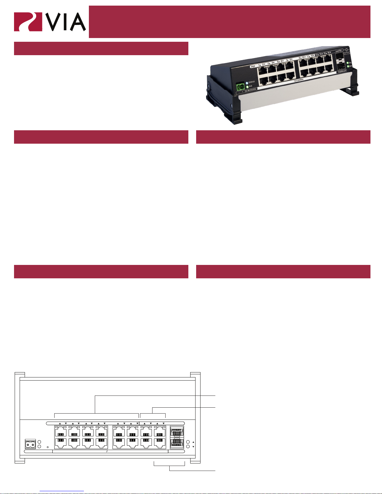
Model 6716 VIA16 Ethernet Switch
OVERVIEW
The VIA16 is a DIN-mountable, managed 10/100 Ethernet
switch with sixteen copper ports and two gigabit mini GBIC
ports for SFP modules.
This compact switch is designed speccally for sACN
data distribution and is ideal for networks usings Pathport
Gateways, Choreo controllers, Cognito consoles
and NSB or Vignette architectural wall stations, with
Power-over-Ethernet support for up to 12 devices.
CONNECTIONS STATUS INDICATORS
Installation
Guide
POWER
The 6716 is designed to run Class 3 PoE on ports 1-12. Typically
most Pathport and Vignette devices are Class 2 or lower and a 100W
48VDC power supply (P/N 1001-100-48-DIN) will supply enough
power for the switch and 12 connected PoE devices. Observe
correct polarity when wiring DC IN plug.
PoE After boot up, solid green indicates PoE is available.
O indicates power supply voltage is not sucient to
supply PoE capability. Flashing green indicates PoE
External Supply value set to 0
STATUS Flashing blue (heartbeat) indicates power and
processor OK; o indicates no power.
ETHERNET
All network wiring should follow standard Ethernet rules and be
installed by a qualied person. As part of the installation, all wiring
should be certied under the TIA/EIA-568 standard.
Fiber Port
LEDS
(17/18)
Green. Intermittent blinking indicates valid link to
other device. Solid red indicates incompatible ber
transceiver.
Pathway recommends the use of manufactured rather than
hand-terminated cables. We also recommend 2100-DIN eDIN RJ45
patch which come in lots of 4 and use 3.5” of rail space. These
use standard punch-down female connectors and essentially build
a patch bay in the eDIN enclosure.
RJ45 LEDs Amber. Intermittent blinking indicates valid link to
other device. For each pair of ports, the left LED will
show link status of the upper port while the right LED
will show status of the lower port.
INSTALLATION FURTHER CONFIGURATION
Disconnect all power before proceeding with installation.
Securely mount DIN rail (if not already installed in the enclosure).
Hook the upper slots on the back of the plastic extrusion to the DIN
rail and then gently but rmly press on the bottom front corners of
the extrusion to snap the module onto the rail.
Connect the DC IN terminal, after checking that polarity is correct.
The VIA16 will boot up, which may take 15-20 seconds.
Attach required network cables to RJ45 ports. Connect the ber
module(s), if used.
The system is now ready for conguration and testing.
All eld conguration of the VIA16 must be done with Pathscape
software.
Download the software from www.pathwayconnect.com and install.
Set computer’s IP to a static address in the 10.x.x.x range, with
a subnet mask of 255.0.0.0 and default gateway of 10.0.0.1. No
conguration of the computer’s DNS settings should be required.
Plug into the VIA16 and launch the software. Discovery will be
automatic.
Refer to software documentation for description of conguration
options.
PoE-enabled ports (1-12)
Non-PoE Ports (13-16)
21 43 65 87 109 1211 1413 1615
PoE
STATU S
PoE
-
+ DC IN 20-50V 10 100Mbit 1000BaseX
6716-300-REV1 05/29/18
NON-PoE
17
18
Ethernet ports are numbered
top to bottom, left to right.
Top row: 1, 3, 5, 7, 9, 11, 13, 15
Bottom row: 2, 4, 6, 8, 10, 12, 14, 16
EAPS Ring Protect-enabled ports
(Ethernet ports 15-16 and Fiber
ports 17-18)
Page 2
DEFAULT SETTINGS
Model 6716 VIA16 Ethernet Switch
Installation
Guide
IP Address Static, set at 10.x.x.x (where x is a number
between 0 and 254)
Subnet Mask 255.0.0.0
Default Gateway 10.0.0.1
VLANs Disabled (all ports run as untagged on VLAN
ID #1)
Mgmt VLAN VLAN ID#1
PoE Supply External supply value set to zero watts (PoE
eectively disabled)
Port PoE Enabled. Above value must be set >5W
before a PoE device will boot
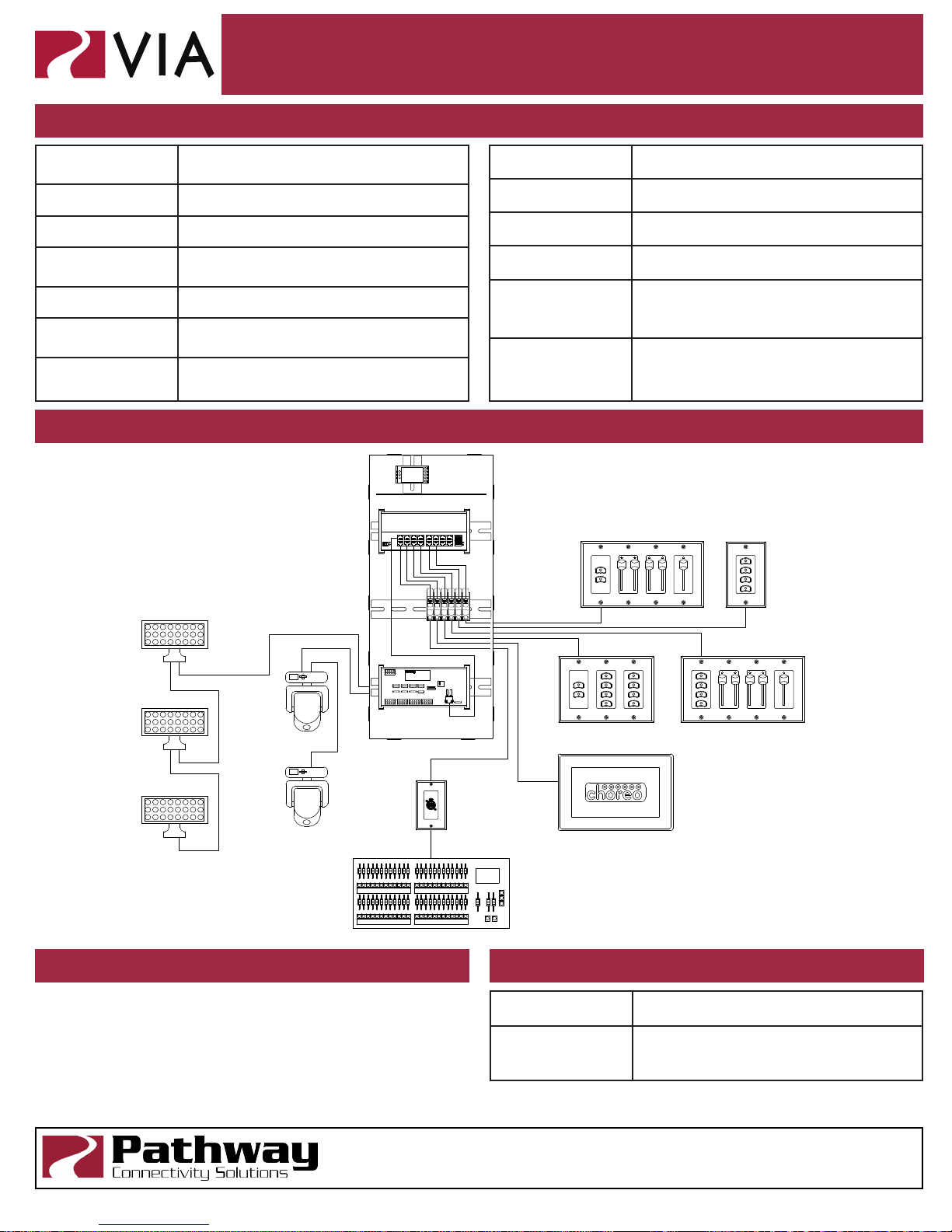
APPLICATION EXAMPLE
1107 eDIN enclosure
6716 VIA16
48VDC 100W
Power Supply
QoS O
Port Link Auto-negotiate
DHCP Disabled
IGMP Disabled
Art-Net to sACN
Disabled
Conversion
Art-Net Alternate
Mapping
Cat5
Patch
Cables
NSB - 2-Button Master (2) 2-Fader Local,
Enabled (only applies when above
feature is enabled)
(1) 1-Fader Local
NSB - 4-Button
Master
Building Cat5
eDIN 4-PORT DMX/RDM GATEWAY
Pathway Connectivity
www.pathwayconnect.com
ACTIVITY
ETHERNET
802.3AF PoE
IDENTIFY
NSB - 2-Button Master, (2) 4-Button
Local
Choreo Architectural Controller
LED Wash Lights
Intelligent Fixtures
2100-DIN
eDIN Patch
POWER IN
18-48VDC
6 Watts MAX
V+V-GRDV-V+
OUTPUT D
OUTPUT C
OUTPUT B
OUTPUT A
INPUT D
INPUT C
INPUT B
INPUT A
ISO PWR D
ISO PWR C
ISO PWR B
ISO PWR A
PORT D
PORT C
PORT B
PORT A
SHLD
COM
SHLD
COM
SHLD
COM
SHLD
COM
D1-
D1+
D1-
D1+
D2-
D2+
D1-
D1+
D2-
D2+
D1-
D1+
D2-
D2+
1014-TRM Pathport
Gateway
Console
REV.0 1321
MICRO-SD
SD CARD OK
PROCESSOR
ETH LINK
D2-
D2+
Pathway Modular Receptacle
(EtherCon)
ELECTRICAL INFORMATION ACCESSORIES
• Power input:
• Switch Only: 20-50 VDC, 10 watts maximum
• Full PoE Support: 48-50VDC, 190 watts maximum
(180 watts for 12 PoE devices)
• PoE Ports: Class 3, 15.4 watts maximum per port, x12
2100-DIN eDIN RJ45 patch (lot of 4) (3.5” of rail for 4)
1001-100-48-DIN 100 Watt, 48VDC Power Supply,
DIN-mountable
NSB - 2-Button Master, (2) 2-Fader Local,
(1) 1-Fader Local
Pathway Connectivity Solutions
#103—1439 17Avenue SE Calgary AB
Canada T2G 1J9
support@pathwayconnect.com
www.pathwayconnect.com
tel (403) 243-8110 fax (403) 287-1281
6716-300-REV1 05/29/18
 Loading...