

Page 1

Full HD Battery IP Cam
User Manual
Page 2
2
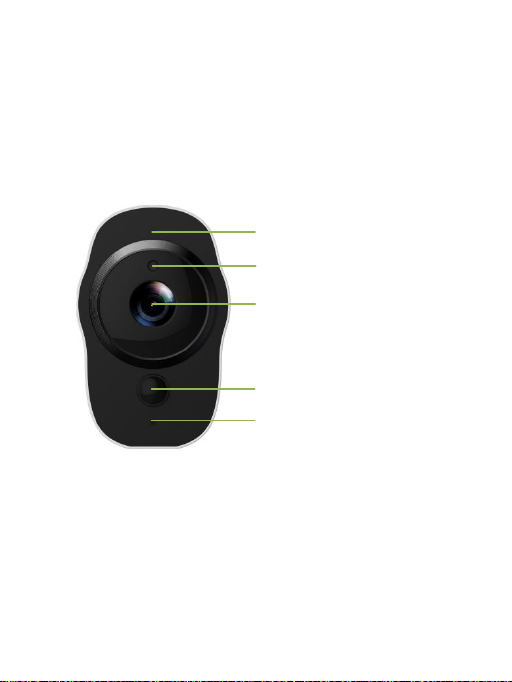
1. Overview
210°鱼眼摄像头
Mic
Ambient Light Sensor
Lens
LED
PIR Sensor
Full HD Battery IP Camera
Page 3
3
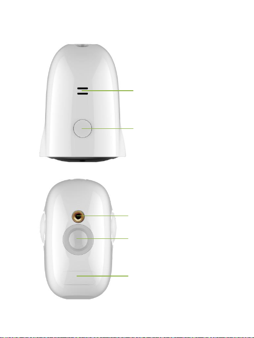
Wall Mount
Magnetic Base
Micro USB Interface and
Micro SD Card Slot
Power
Speaker
Page 4
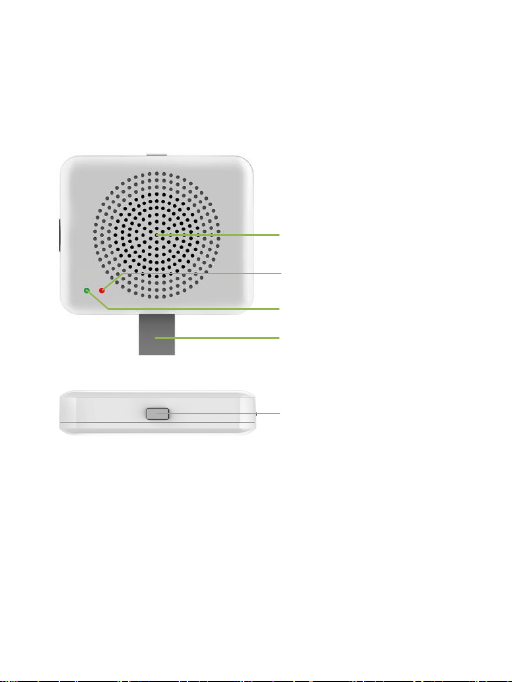
4
Speaker
Red LED
Green LED
USB Interface
Reset Button
Sync Module
Page 5
5
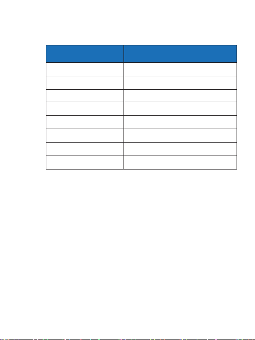
Item
Description
Camera Sensor
1/2.7" 1080P CMOS
Camera Lens
Field Angle:138°
Image Resolution
Max.1920X1080
Video Bitrate
Auto Adapter
Storage
Micro SD Card (MAX.128GB)
Battery
4020mAH
Power Supply
5V/1.5A
Dimensions
77mm x 66mm x 48mm
1.1 Specifications
Packing List:
• Full HD Battery IP Camera
• Micro USB charging cable
• Sync Module(Optional)
• User Manual
• Warranty Card
Page 6

6
2. Getting Started with your IP Camera
Full HD Battery IP Camera supports Android
phones and iPhone connections. The camera
supports automatic video recording to Micro
SD card after startup, and can be played back
in mobile App. To use this feature, you need to
insert a Micro SD card into the camera.
Insert Micro SD Card: When inserting a Micro
SD card, use your fingernail to press the card
into the camera. When it is fully inserted, the
card will snap into the slot. To remove the
Micro SD card, use your fingernail to gently
press the card into the camera and it will pop
up, allowing you to remove it.
*Note: Micro SD must be formatted in a FAT32
file system format.
2.1 Powering On, Off and Recharging
Turn On: Press the power button for 2
seconds until you hear “power up”, then
release. When the green LED light turns on,
your IP Camera is on.
*Note: The first time the camera is turned on,
the camera will automatically scan for a
connection, indicated by a flashing green LED
light and play “scan QR code”. Please use the
VPai Home App to configure the camera
network, details refers to ‘Using Your IP
Camera with a phone’.
Page 7

7
Turn Off: Press and hold the power button for 2
seconds until hearing “power down”, then release.
When the green LED light turns off, your IP Camera
has powered down.
Charge the Battery: If the IP Camera’s battery is
low on power, the camera battery icon on the live
screen of the VPai Home App will flash. Please use
the Micro USB cable to insert the 5V/1.5A charging
adapter to charge the camera.
*Note: When the battery is too low, the red LED
light will flash quickly for 15 seconds and play "low
battery, system will shut down". If not charged, the
device will be shut down automatically.
Page 8
8
2.2 Using Your IP Camera with a phone
The camera supports connecting with android
phone and iPhone. In order to use your camera,
installation of the official VPai Home App is
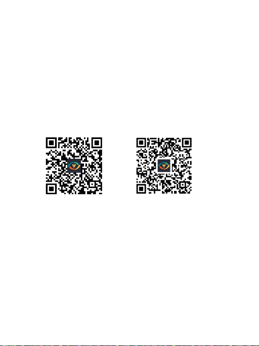
required. You can scan the QR code below to
download and install the VPai Home App
according to your phone system. App for
Android is also supplied on VPai website
(www.vpai360.com), Google Play Store, Baidu
App assistant, Tencent mobile assistant, and
Peasecod platform and so on.
QR code for Android QR code for iOS
*Note: Android 5.0 or iOS 9.0 above is
required.
The camera supports the connection of the
wireless router or Sync Module.
Sync module is central hub of your IP Camera
system. This connects to your Wi-Fi network
and to your IP Camera(s).
Page 9

9
Camera connects to wireless router: Once the
VPai Home App has been installed on your phone,
open the App and choose to log on to the App with
your WeChat, Facebook or LINE account. Click the
add device button “+” on the App to Enter the add
device wizard. The screen prompts will show as
follows:
Page 10
10
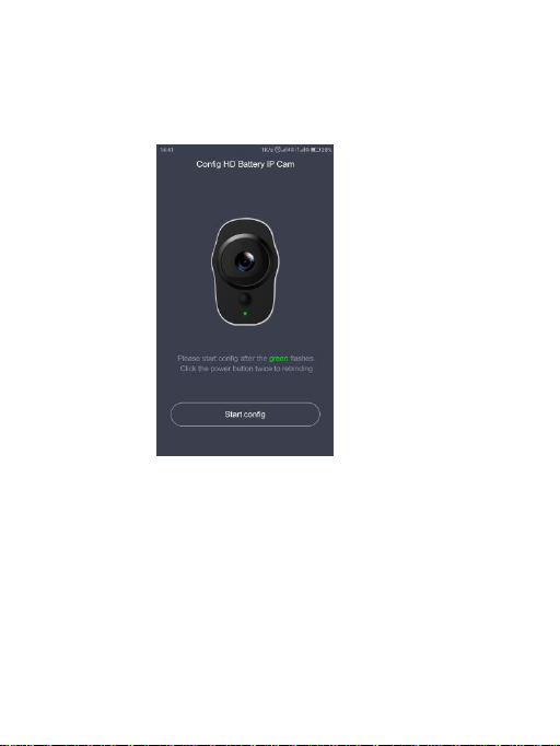
Select “HD Battery IP Cam” to enter the
“Configure HD Battery IP Cam” interface. The
screen prompts show as follows:
Page 11

11
Click “Start config” to enter the “Config Wi-Fi”
interface. Then click the Wi-Fi name drop-down
arrow and select the Wi-Fi hotspot (the iPhone
requires manual input), and enter the password.
The Wi-Fi configuration will show as below:
Page 12

12
Click “next” and then use your IP Camera to
scan the QR code on the App (allow 15-25cm
distance). Please follow the on-screen
instructions as below.
*Note: After the QR code has been
successfully scanned, you will hear “scan
finished” and the camera will start to connect to
the router. The green LED light will continue to
flash until the Wi-Fi connection is established.
You will hear “Wi-Fi connected” when the
connection is successful. The Wi-Fi connection
information will be automatically saved. The
next time the camera is switched on, the Wi-Fi
will connect automatically. If the Wi-Fi
disconnects, a red LED light will flash.
Page 13

13
Camera connects to Sync Module: Click the add
device “+” button on the App and select “Sync
Module” in “Select Devices” interface. The screen
prompts will show as follows:
Page 14
14
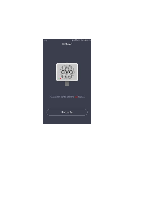
Connect the Sync Module to the power supply.
Click “Start config” when the red LED light
starts flashing.
Click the “Config Wi-Fi” button and select the
Wi-Fi hotspot named VPaiHome_xxxx. The
password is: 12345678. After the connection is
successful, the "Config exist Wi-Fi" button
becomes clickable when return to “Config AP”
interface. The screen prompts will show as
follows:
Page 15

15
After connected with Sync Module, click "Config
exits Wi-Fi" to enter next page. You can change its
Wi-Fi name and password by click "Change name
and password"; or click "Next" to connect the Sync
Module to internet. Show as below.
Page 16

16
Click "Change name and password", enter a
name and password, and click "Next" to
complete the setup. After that, you need to
reconnect to the Sync Module’s Wi-Fi you just
set up. Change the name and password
settings as shown below:
Page 17

17
In “Config exist Wi-Fi” interface, you can click “Next”
connect your Sync Module to the Internet. Click the
Wi-Fi name drop-down arrow (the iPhone requires
manual input), select the Wi-Fi hotspot which can
connect with internet and enter the password. The
Sync Module will restart after click “Next”. When the
Sync Module is connected to the internet, the red
LED light will stop flashing and turn on. Config
interface showed as below.
Page 18

18
The Sync Module's Wi-Fi can be used as a
normal wireless network after the internet
configuration of the Sync Module is completed.
You can connect the camera to the internet
through the Sync Module. For the connection
steps of the camera and the Sync Module’s WiFi, please refer to ‘Camera connects to
wireless router’ as mentioned above.
Page 19

19
After the camera has been successfully added, you
can modify its name. Then click “OK” the App will
return to the home page. The added phase is
displayed on the home page. Click the camera
preview to enter the camera operation interface.
You can view the camera’s real-time image, take
photos, record videos, and send voice messages
and so on. The camera operation interface will show
as follows:
For full App instructions please visit the official
website. Instructions for Android:
www.vpai360.com/en/apps/home/android/;
Instructions for iOS:
www.vpai360.com/en/apps/home/apple/.
Page 20

20
2.3 Full HD Battery IP Camera Firmware
Update
When you connect your IP Camera to your
phone through the VPai Home App, it will
automatically detect the latest firmware and
prompt you when a new firmware upgrade is
available. If you accept to install the firmware
upgrade, the green LED light will flash quickly
and the camera will play “upgrading” at the
same time. When the firmware upgrade is
complete, the green LED light stops flashing
and turn on and the camera play “upgrading
finished”. The camera will restart after upgrade
has finished.
*Note: Make sure that your IP Camera is fully
charged or connected to the power adapter
before upgrading the firmware. Do not power
off the camera during the upgrade process.
2.4 FCC Caution
This device complies with part 15 of the FCC
Rules. Operation is subject to the following two
conditions: (1) This device may not cause
harmful interference, and (2) this device must
accept any interference received, including
interference that may cause undesired
operation.
Note: This equipment has been tested and
found to comply with the limits for a Class B
digital device, pursuant to part 15 of the FCC
Rules. These limits are designed to provide
reasonable protection against harmful
Page 21

21
interference in a residential installation. This
equipment generates uses and can radiate
radio frequency energy and, if not installed and
used in accordance with the instructions, may
cause harmful interference to radio
communications. However, there is no
guarantee that interference will not occur in a
particular installation. If this equipment does
cause harmful interference to radio or
television reception, which can be determined
by turning the equipment off and on, the user is
encouraged to try to correct the interference by
one or more of the following measures:
-Reorient or relocate the receiving antenna.
-Increase the separation between the
equipment and receiver.
-Connect the equipment into an outlet on a
circuit different from that to which the receiver
is connected.
-Consult the dealer or an experienced radio/TV
technician for help.
Any Changes or modifications not expressly
approved by the party responsible for
compliance could void the user's authority to
operate the equipment.
Page 22

22
SAR Statement
This device was tested for typical body-support
operations. To comply with FCC RF exposure
requirements, a minimum separation distance
of 0cm can be maintained between the user’s
body and the device, including the antenna
without any restrictions. Third-party belt-clips,
holsters, and similar accessories used by this
device should not contain any metallic
components. Body accessories that do not
meet these requirements may not comply with
RF exposure requirements and should be
avoided. Use only the supplied or an approved
antenna.
The Maximum 1-g report body SAR is
0.266W/kg less than the FCC SAR limit of
1.6W/kg.
 Loading...