

Page 1

1.02-01042013-141500
USER MANUAL
VAB-800
Pico-ITX Freescale Cortex-A8 board
Page 2
Tested To Comply
With FCC Standards
FOR HOME OR OFFICE USE
Copyright
Copyright © 2012 VIA Technologies Incorporated. All rights reserved.
No part of this document may be reproduced, transmitted, transcribed, stored in a retrieval system, or translated into any language,
in any form or by any means, electronic, mechanical, magnetic, optical, chemical, manual or otherwise without the prior written
permission of VIA Technologies, Incorporated.
Trademarks
All trademarks are the property of their respective holders.
Disclaimer
No license is granted, implied or otherwise, under any patent or patent rights of VIA Technologies. VIA Technologies makes no
warranties, implied or otherwise, in regard to this document and to the products described in this document. The information
provided in this document is believed to be accurate and reliable as of the publication date of this document. However, VIA
Technologies assumes no responsibility for the use or misuse of the information in this document and for any patent infringements
that may arise from the use of this document. The information and product specifications within this document are subject to
change at any time, without notice and without obligation to notify any person of such change.
VIA Technologies, Inc. reserves the right the make changes to the products described in this manual at any time without prior
notice.
Regulatory Compliance
FCC
FCCFCC
FCC----A Radio Frequency Interference Statement
A Radio Frequency Interference StatementA Radio Frequency Interference Statement
A Radio Frequency Interference Statement
This equipment has been tested and found to comply with the limits for a class A digital device, pursuant to part 15 of the FCC
rules. These limits are designed to provide reasonable protection against harmful interference when the equipment is operated in a
commercial environment. This equipment generates, uses, and can radiate radio frequency energy and, if not installed and used in
accordance with the instruction manual, may cause harmful interference to radio communications. Operation of this equipment in a
residential area is likely to cause harmful interference, in which case the user will be required to correct the interference at his
personal expense.
Notice 1
Notice 1Notice 1
Notice 1
The changes or modifications not expressly approved by the party responsible for compliance could void the user's authority to
operate the equipment.
Notice 2
Notice 2Notice 2
Notice 2
Shielded interface cables and A.C. power cord, if any, must be used in order to comply with the emission limits.
Page 3

Battery Recycling and Disposal
Only use the appropriate battery specified for this product.
Do not re-use, recharge, or reheat an old battery.
Do not attempt to force open the battery.
Do not discard used batteries with regular trash.
Discard used batteries according to local regulations.
Safety Precautions
Always read the safety instructions carefully.
Keep this User's Manual for future reference.
All cautions and warnings on the equipment should be noted.
Keep this equipment away from humidity.
Lay this equipment on a reliable flat surface before setting it up.
Make sure the voltage of the power source and adjust properly 110/220V before connecting
the equipment to the power inlet.
Place the power cord in such a way that people cannot step on it.
Always unplug the power cord before inserting any add-on card or module.
If any of the following situations arises, get the equipment checked by authorized service
personnel:
The power cord or plug is damaged.
Liquid has penetrated into the equipment.
The equipment has been exposed to moisture.
The equipment has not worked well or you cannot get it work according to User's Manual.
The equipment has dropped and damaged.
The equipment has obvious sign of breakage.
Do not leave this equipment in an environment unconditioned or in a storage temperature
above 60°C (140°F). The equipment may be damaged.
Do not leave this equipment in direct sunlight.
Never pour any liquid into the opening. Liquid can cause damage or electrical shock.
Do not place anything over the power cord.
Do not cover the ventilation holes. The openings on the enclosure protect the equipment
from overheating
Page 4

VAB
VABVAB
VAB----800
800800
800 User Manual
User ManualUser Manual
User Manual
iv
Box Contents and Ordering Information
VAB
VABVAB
VAB----800
800800
800
1 x VAB-800
1 x DC jack power cable
1 x Audio cable
1 x CAN BUS/USB cable
1 x COM cable
Page 5

VAB
VABVAB
VAB----800
800800
800 User Manual
User ManualUser Manual
User Manual
v
Table of Contents
1.
1.1.
1. Product Overview
Product OverviewProduct Overview
Product Overview................................
................................................................
................................................................
................................................................
................................................................
................................................................
................................ 1111
1.1.
Key Features................................................................................................... 2
1.2.
Product Specifications................................................................................. 3
1.3.
Layout Diagram ............................................................................................. 5
1.4.
Product Dimensions..................................................................................... 7
1.5.
Height Distribution....................................................................................... 8
2.
2.2.
2. I/O Interface
I/O InterfaceI/O Interface
I/O Interface................................
................................................................
................................................................
................................................................
................................................................
................................................................
..........................................
....................
.......... 9999
2.1.
External I/O Ports ......................................................................................... 9
2.1.1.
LAN port: Fast Ethernet ....................................................................... 10
2.1.2.
USB 2.0 Port ........................................................................................... 11
2.1.3.
Mini HDMI® Port.................................................................................... 12
2.1.4.
VGA Port................................................................................................. 13
2.2.
Onboard Connectors ................................................................................ 14
2.2.1.
LVDS1 & LVDS2 Connectors .............................................................. 14
2.2.2.
SATA Connector ................................................................................... 16
2.2.3.
USB/USB device/CAN/RST/PWNON Combination Pin Header.. 18
2.2.4.
DIO + Touch + I2C Combination Pin Header................................. 20
2.2.5.
F_Audio Pin Header ............................................................................. 21
2.2.6.
External SATA Power Connector...................................................... 22
2.2.7.
SATA DOM Power Select................................................................... 23
2.2.8.
COM1 Connector.................................................................................. 24
2.2.9.
COM2 Connector.................................................................................. 25
2.2.10. RTC Battery Connector ........................................................................ 26
2.2.11. DC-In Power Connector ...................................................................... 27
2.2.12. J_TAG Connector.................................................................................. 28
2.2.13. Boot Select............................................................................................. 29
2.2.14. CAN BUS................................................................................................. 30
3.
3.3.
3. Hardware Installation
Hardware InstallationHardware Installation
Hardware Installation ................................
................................................................
................................................................
................................................................
........................................................
................................................
........................ 31
3131
31
Page 6

VAB
VABVAB
VAB----800
800800
800 User Manual
User ManualUser Manual
User Manual
vi
3.1.
Installing into a Chassis............................................................................. 31
3.1.1.
Suggested minimum chassis dimensions ......................................... 31
3.1.2.
Suggested minimum chassis height................................................... 32
3.1.3.
Suggested keepout areas .................................................................... 33
3.2.
Connection of Cables ............................................................................... 34
4.
4.4.
4. Making Ubuntu Demo Image
Making Ubuntu Demo ImageMaking Ubuntu Demo Image
Making Ubuntu Demo Image ................................
................................................................
................................................................
................................................................
............................................
........................
............ 35
3535
35
4.1.
Getting Ubuntu demo image................................................................... 35
4.2.
Making demo image into Micro SD........................................................ 38
4.3.
Replace U-boot/Kernel/Modules of VAB-800..................................... 38
4.4.
Setting U-boot ............................................................................................ 43
4.5.
Making demo image to eMMC (optional) ............................................ 46
Appendix A. Starter Kit
Appendix A. Starter KitAppendix A. Starter Kit
Appendix A. Starter Kit................................
................................................................
................................................................
................................................................
..............................................................
............................................................
.............................. 47
4747
47
A.1. Starter Kit Assembly .......................................................................................... 47
A.2. VAB-800-A Specifications ................................................................................ 49
A.3. VAB-800-A Layout.............................................................................................. 50
A.4. VAB-800-A Pinouts and Jumpers.................................................................... 51
Appendix B. Mating Connector Vendor Lists
Appendix B. Mating Connector Vendor ListsAppendix B. Mating Connector Vendor Lists
Appendix B. Mating Connector Vendor Lists................................
................................................................
..........................................................
....................................................
.......................... 53
5353
53
Page 7

VAB
VABVAB
VAB----800
800800
800 User Manual
User ManualUser Manual
User Manual
vii
Lists of Figures
Figure 1: Layout diagram of the VAB-800 mainboard (top and bottom view) ... 5
Figure 2: Mounting holes and dimensions of the VAB-800 ..................................... 7
Figure 3: Height distribution of the VAB-800 mainboard ........................................ 8
Figure 4: External I/O ports............................................................................................. 9
Figure 5: Fast Ethernet port pinout diagram.............................................................. 10
Figure 6: USB 2.0 port pinout diagram ....................................................................... 11
Figure 7: Mini HDMI® port pinout diagram................................................................ 12
Figure 8: VGA port pinout diagram............................................................................. 13
Figure 9: LVDS1 and LVDS2 connectors .................................................................... 14
Figure 10: SATA connectors ......................................................................................... 16
Figure 11: USB/USB device/CAN/RST/ PWNON combination pin header......... 18
Figure 12: DIO + Touch + I2C combination pin header ........................................ 20
Figure 13: F_Audio pin header ..................................................................................... 21
Figure 14: External SATA Power connector.............................................................. 22
Figure 15: SATA DOM Power select .......................................................................... 23
Figure 16: COM1 connector ......................................................................................... 24
Figure 17: COM2 connector ......................................................................................... 25
Figure 18: RTC Battery connector ................................................................................ 26
Figure 19: DC-In Power connector.............................................................................. 27
Figure 20: J_Tag connector ........................................................................................... 28
Figure 21: Boot Select jumper...................................................................................... 29
Figure 22: CAN BUS jumper ......................................................................................... 30
Figure 23: Suggested minimum chassis dimensions ................................................ 31
Figure 24: Suggested minimum internal chassis ceiling height............................. 32
Figure 25: Suggested keepout areas ........................................................................... 33
Figure 26: Connection of cables (top view) ............................................................. 34
Figure 27: Connection of cables (bottom view)...................................................... 34
Figure 28: Connecting VAB-800-A to VAB-800 mainboard .................................. 47
Figure 29: Connection of panel.................................................................................... 48
Figure 30: VAB-800-A Layout (top view) .................................................................. 50
Figure 31: VAB-800-A Layout (bottom view) ........................................................... 50
Page 8

VAB
VABVAB
VAB----800
800800
800 User Manual
User ManualUser Manual
User Manual
viii
Lists of Tables
Table 1: Layout diagram description table of the VAB-800 mainboard .............. 6
Table 2: Layout diagram description table of external I/O ports .......................... 9
Table 3: Fast Ethernet port pinout .............................................................................. 10
Table 4: Fast Ethernet LED color definition .............................................................. 10
Table 5: USB 2.0 port pinout........................................................................................ 11
Table 6: HDMI® port pinout ......................................................................................... 12
Table 7: VGA port pinout ............................................................................................. 13
Table 8: LVDS1 connector pinout ............................................................................... 15
Table 9: LVDS2 connector pinout ............................................................................... 15
Table 10: SATA connector pinouts............................................................................. 17
Table 11: USB/USB device/CAN/RST/PWNON combination pin header pinout
............................................................................................................................................. 19
Table 12: DIO + Touch + I2C combination pin header pinout ........................... 20
Table 13: F_Audio pin header pinout ........................................................................ 21
Table 14: External SATA Power connector pinout................................................. 22
Table 15: SATA DOM Power select........................................................................... 23
Table 16: COM1 connector pinout............................................................................. 24
Table 17: COM2 connector pinout............................................................................. 25
Table 18: RTC battery connector pinout ................................................................... 26
Table 19: DC-In Power connector .............................................................................. 27
Table 20: J_Tag connector............................................................................................ 28
Table 21: Boot Select jumper settings ....................................................................... 29
Table 22: CAN BUS jumper settings........................................................................... 30
Table 23: VAB-800 mating connector vendor lists ................................................. 53
Page 9

VAB
VABVAB
VAB----800
800800
800 User Manual
User ManualUser Manual
User Manual
1
1.
1.1.
1. Product Overview
Product OverviewProduct Overview
Product Overview
Based on the ultra compact Pico-ITX form factor, measuring 10 cm x 7.2 cm,
the VIA VAB-800 is the first VIA Pico-ITX board to feature an ARM SoC. With
the choice of either an 800MHz or 1GHz Freescale Cortex-A8 ARM SoC, the
VIA VAB-800 combines two integrated GPUs for dual displays and 3D/2D
graphics acceleration to provide full HD playback support for resolutions up
to 1080p.
The ultra compact VIA VAB-800 Pico-ITX is optimized for both performance
and power to meet the high end demands of advanced industrial and in-
vehicle applications, boasting a ruggedized design with a wide operating
temperature range from -20 to 70°C, while offering extremely low power
consumption of a maximum 5W TDP. In addition to the ruggedized design VIA
offers up to 7 years longevity support.
The VIA VAB-800 provides an impressive selection of rear I/O in a compact
form factor including VGA and Mini HDMI ports, two USB 2.0 ports and one
Ethernet port. Customers can take advantage of VIA’s industry leading
hardware and software support to create customized designs with a quick time
to market. The VIA VAB-800 is also available with board support packages
(BSP) for the Android and Embedded Linux 2.6 operating systems (BSP for
Windows Embedded Compact 7 is only available through third party).
On board pin headers provide support for an additional of two USB 2.0 ports,
one SATA connectors, two COM pin headers, two single channel LVDS
connectors, one micro SD connector and eight GPIO pin headers, etc.
Page 10

VAB
VABVAB
VAB----800
800800
800 User Manual
User ManualUser Manual
User Manual
2
1.1. Key Features
Supports integrated graphics processing (GPU) for 3D/2D graphics
acceleration and dual displays
Supports two single-channel 18/24-bit LVDS connectors
Supports four USB ports (two as pin headers) and one USB device port
Supports two COM ports
Supports mini-HDMI and VGA ports
Small form factor and low power design
Page 11

VAB
VABVAB
VAB----800
800800
800 User Manual
User ManualUser Manual
User Manual
3
1.2. Product Specifications
Processor
ProcessorProcessor
Processor
Freescale Cortex-A8 Single-Core i.MX537 @800MHz (Optional for i.MX535 @1.0GHz)
Flash
FlashFlash
Flash
eMMC Flash (up to 64GB)
SPI Serial Flash (up to 4MB) (Optional and shared with COM1 port)
Graphics
GraphicsGraphics
Graphics
Support two independent, integrated graphics processing units: an OpenGL® ES 2.0
3D graphics accelerator and an OpenVG™ 1.1 2D graphics accelerator
System Memory
System MemorySystem Memory
System Memory
1GB DDR3-800 SDRAM using 128M x16 memory devices
Ethernet
EthernetEthernet
Ethernet
SMSC LAN8720A 10/100 PHY Transceiver with HP Auto-MDIX support
Audio
AudioAudio
Audio
Freescale SGTL5000 Low Power Stereo Codec with Headphone Amp
HDMI
HDMIHDMI
HDMI
Silicon Image SiI9024A HDMI Transmitter
CAN
CANCAN
CAN
TI SN65HVD1050 EMC Optimized CAN transceiver
USB Hub
USB HubUSB Hub
USB Hub
SMSC USB 2.0 High Speed 4-Port Hub Controller
Onboard I/O
Onboard I/OOnboard I/O
Onboard I/O
1 X SATA I connector with voltage select jumper
1 X SATA DOM power supply connector
1 X Micro SD connector
2 X COM connectors with power supply (one supports 8-wire, the other supports 2-
wire)
2 X Single-channel, 18/24-bit LVDS connectors
1 X RTC battery pin header
1 X Front audio pin header for line-in, line-out and MIC-in
Page 12

VAB
VABVAB
VAB----800
800800
800 User Manual
User ManualUser Manual
User Manual
4
1 X JTAG connector
1 X Boot flash select pin header
1 X miscellaneous pin header for 2 USB2.0 ports, 1 USB device port, 2 CAN bus ports,
system power-on and reset
1 X miscellaneous pin header for 4-wire resistive touch screen interface, 1 I²C pair and
8 GPIOs
1 X 5V DC-in power connector
Back
BackBack
Back Panel I/O
Panel I/O Panel I/O
Panel I/O
1 X VGA port
2 X USB 2.0 ports
1 X Mini HDMI port
1 X RJ-45 LAN port
WatchDog Timer
WatchDog TimerWatchDog Timer
WatchDog Timer
Integrated WatchDog timer supports two comparison points. Each comparison point
can interrupt ARM core, 2nd comparison point capable of generating external
interrupts on WDOG line
Power
PowerPower
Power
2W typical, 5W max.
Operating System
Operating SystemOperating System
Operating System
Android 2.3
Embedded Linux 2.6
Win CE 7.0 (through 3rd party)
Operating Conditions
Operating ConditionsOperating Conditions
Operating Conditions
Operating Temperature
Operating TemperatureOperating Temperature
Operating Temperature
0°C ~60°C (-20°C ~ 70°C for option)
Operating Humidity
Operating HumidityOperating Humidity
Operating Humidity
0% ~ 95% (relative humidity; non-condensing)
Form Factor
Form FactorForm Factor
Form Factor
Pico-ITX (8-layers)
10 cm x 7.2 cm
Note:
Note: Note:
Note:
For the software evaluation, please contact your regional sales or Field Applications Engineer to get
the software download link.
Page 13
VAB
VABVAB
VAB----800
800800
800 User Manual
User ManualUser Manual
User Manual
5
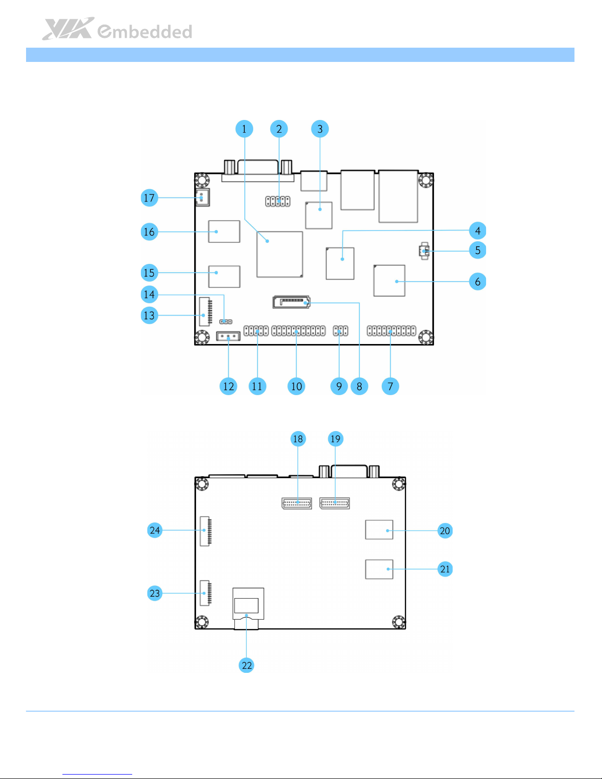
1.3. Layout Diagram
Figure
Figure Figure
Figure 1111: Layout diagram of the
: Layout diagram of the : Layout diagram of the
: Layout diagram of the VAB
VABVAB
VAB----800
800800
800 mainboard
mainboardmainboard
mainboard (top
(top (top
(top and bottom
and bottom and bottom
and bottom view)
view)view)
view)
Page 14

VAB
VABVAB
VAB----800
800800
800 User Manual
User ManualUser Manual
User Manual
6
Item
ItemItem
Item Description
DescriptionDescription
Description
1 i.MX537
2 J4: Boot Select
3 HDMI transmitter
4 eMMC Flash
5 J8: RTC Battery Connector
6 MC34708 PMIC
7 J10: DIO, Touch and I2C combination pin header
8 SATA connector
9 J2: CAN Bus Jumper
10 J9: USB, USB device, CAN, RST and PWNON combination pin header
11 F_audio
12 PWR1: External SATA Power connector
13 COM1
14 J3: SATA DOM Power select
15 DDR3
16 DDR3
17 DC-in power connector
18 LVDS2 connector
19 LVDS1 connector
20 DDR3
21 DDR3
22 SD
23 COM2
24 J_TAG
Table
Table Table
Table 1111:
: :
: Layout diagram description table of the
Layout diagram description table of the Layout diagram description table of the
Layout diagram description table of the VAB
VABVAB
VAB----800
800800
800 mainboard
mainboardmainboard
mainboard
Page 15
VAB
VABVAB
VAB----800
800800
800 User Manual
User ManualUser Manual
User Manual
7
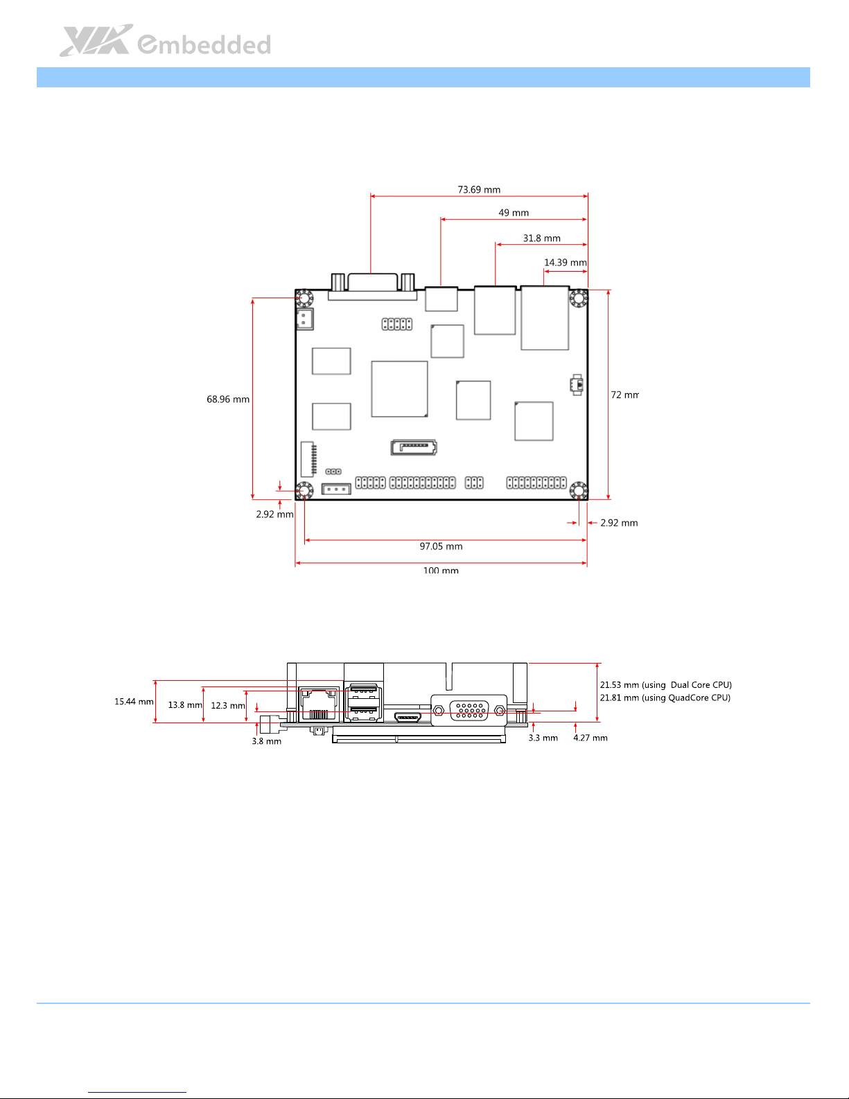
1.4. Product Dimensions
Figure
Figure Figure
Figure 2222:
: :
: Mounting holes and dimensions of
Mounting holes and dimensions ofMounting holes and dimensions of
Mounting holes and dimensions of the
the the
the VAB
VABVAB
VAB----800
800800
800
Page 16
VAB
VABVAB
VAB----800
800800
800 User Manual
User ManualUser Manual
User Manual
8
1.5. Height Distribution
Figure
Figure Figure
Figure 3333: Height distribution of the
: Height distribution of the : Height distribution of the
: Height distribution of the VAB
VABVAB
VAB----800
800800
800 mainboard
mainboard mainboard
mainboard
Page 17
VAB
VABVAB
VAB----800
800800
800 User Manual
User ManualUser Manual
User Manual
9
2.
2.2.
2. I/O Interface
I/O InterfaceI/O Interface
I/O Interface
The VAB-800 has a wide selection of interfaces. It includes a selection of
frequently used ports as part of the external I/O coastline.
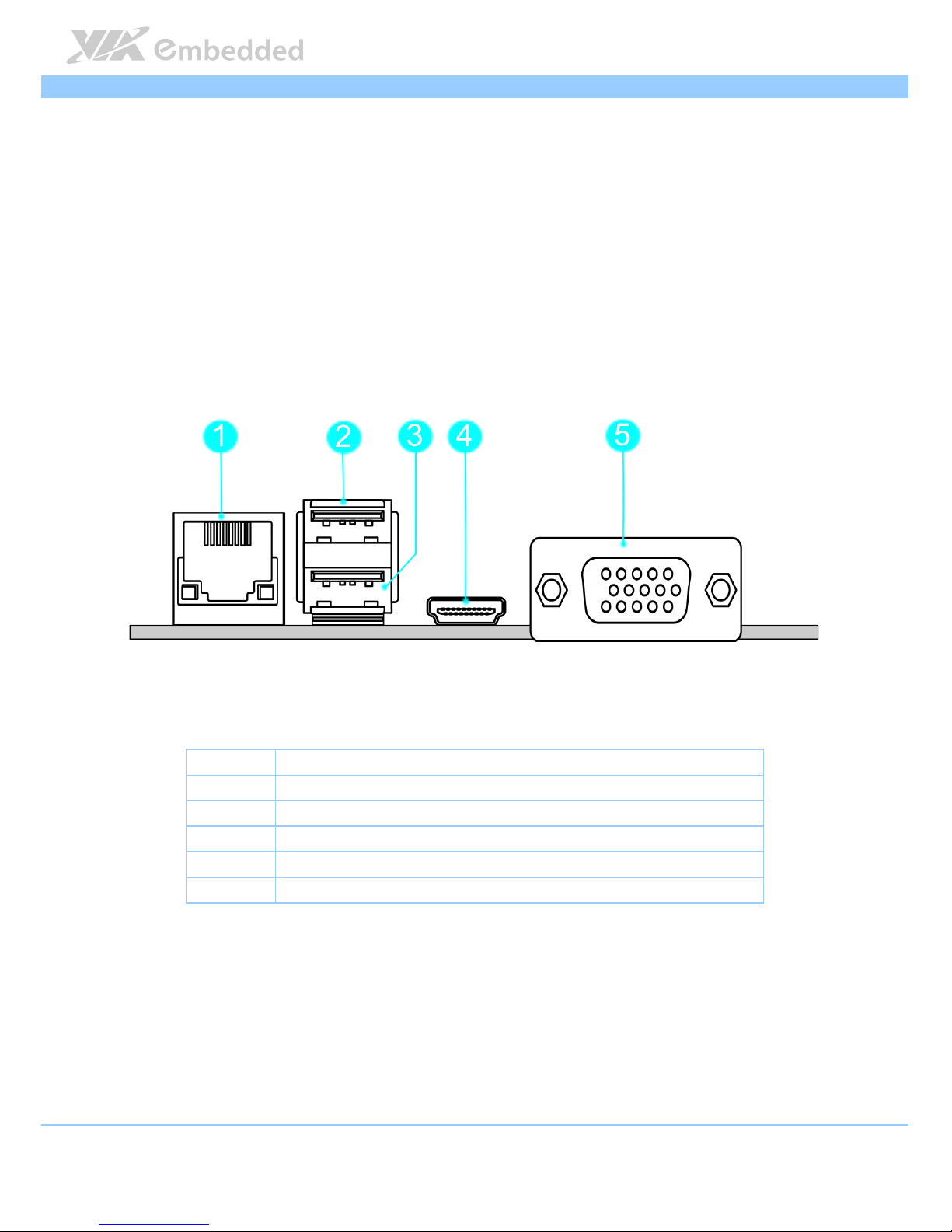
2.1. External I/O Ports
Figure
Figure Figure
Figure 4444: External I/O ports
: External I/O ports: External I/O ports
: External I/O ports
Item
ItemItem
Item Description
DescriptionDescription
Description
1 RJ1: Fast Ethernet LAN port
2 USB1: USB 2.0 port
3 USB2: USB 2.0 port
4 HDMI1: Mini HDMI® port
5 VGA1: VGA port
Table
Table Table
Table 2222: Layout diagram description table of
: Layout diagram description table of : Layout diagram description table of
: Layout diagram description table of external I/O ports
external I/O portsexternal I/O ports
external I/O ports
Page 18
VAB
VABVAB
VAB----800
800800
800 User Manual
User ManualUser Manual
User Manual
10
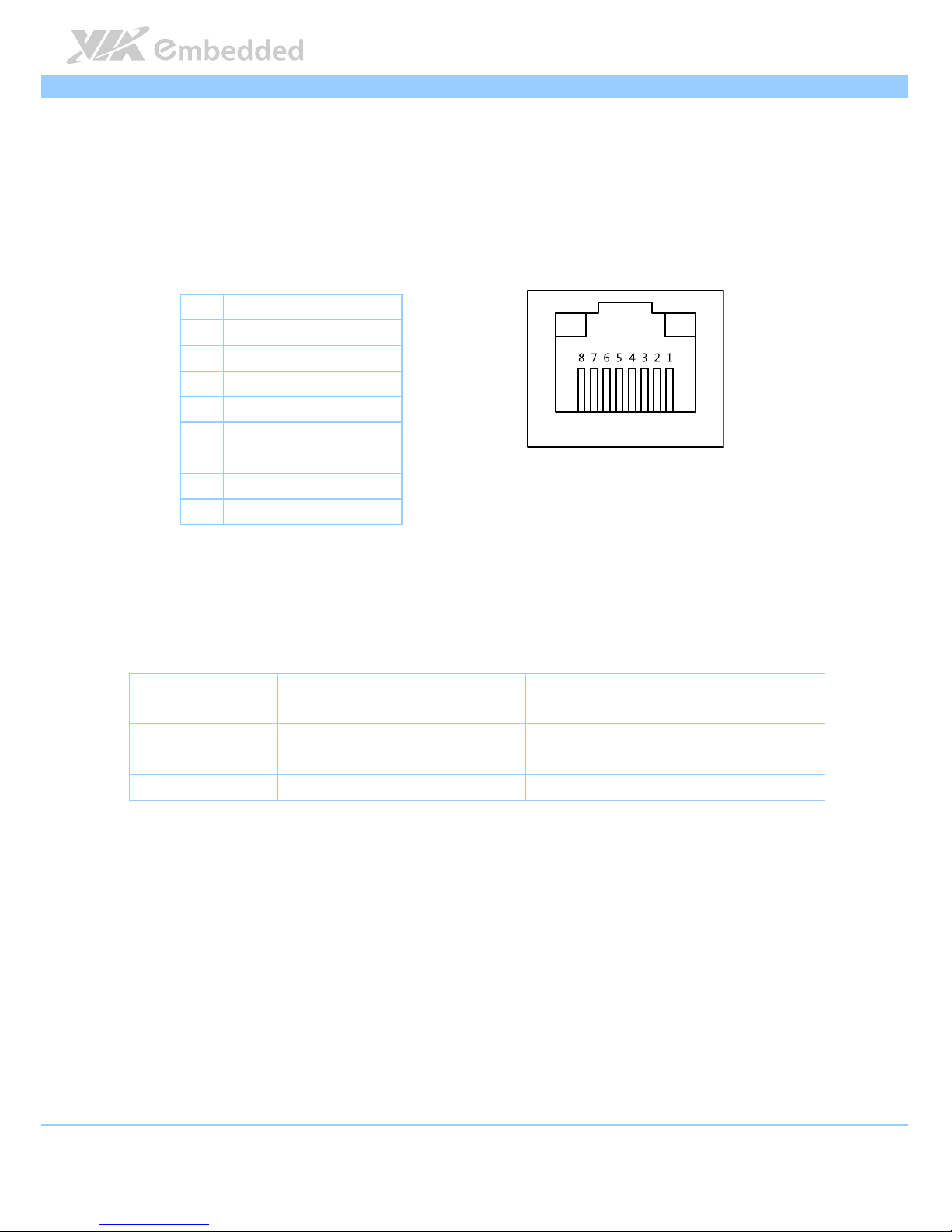
2.1.1. LAN port: Fast Ethernet
The integrated 8-pin Fast Ethernet port is using an 8 Position 8 Contact (8P8C)
receptacle connector (commonly referred to as RJ45). The Fast Ethernet ports
are controlled by VIA Fast Ethernet controller. The pinout of the Fast Ethernet
port is shown below.
Pin
PinPin
Pin
Signal
SignalSignal
Signal
1 TD+
2 TD-
3 RD+
4 REGOUT
5 REGOUT
6 RD-
7 GND
8 GND
Table
Table Table
Table 3333:
: :
: Fast
FastFast
Fast Ethernet port pinout
Ethernet port pinout Ethernet port pinout
Ethernet port pinout
Figur
FigurFigur
Figure
e e
e 5555:
: :
: Fast
FastFast
Fast Ethernet port pinout diagram
Ethernet port pinout diagram Ethernet port pinout diagram
Ethernet port pinout diagram
The RJ-45 port has two individual LED indicators located on the front side to
show its Active/Link status and Speed status.
Active
ActiveActive
Active LED
LED LED
LED
(Left LED on RJ
(Left LED on RJ(Left LED on RJ
(Left LED on RJ----45 connector)
45 connector)45 connector)
45 connector)
Link
LinkLink
Link LED
LED LED
LED
(Right LED on RJ
(Right LED on RJ(Right LED on RJ
(Right LED on RJ----45 connector)
45 connector)45 connector)
45 connector)
Link Off Off Off
Speed_10Mbit Flash in Green color Off
Speed_100Mbit Flash in Green color The LED is always On in Yellow color
Table
Table Table
Table 4444:
: :
: Fast
FastFast
Fast Ethernet LED color de
Ethernet LED color de Ethernet LED color de
Ethernet LED color definition
finitionfinition
finition
Page 19
VAB
VABVAB
VAB----800
800800
800 User Manual
User ManualUser Manual
User Manual
11
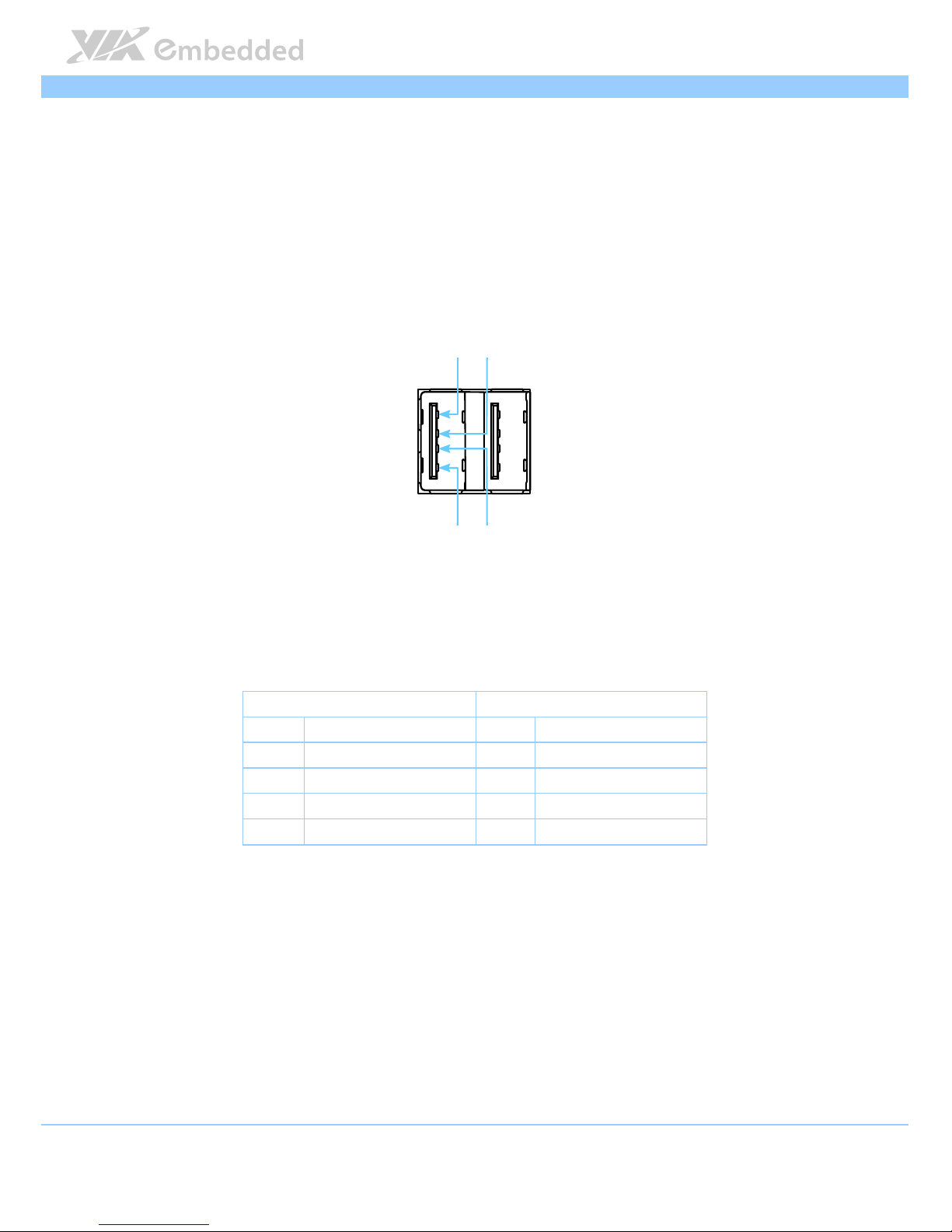
2.1.2. USB 2.0 Port
The VAB-800 mainboard provides two USB 2.0 ports, Each USB port gives
complete Plug and Play and hot swap capability for external devices. The USB
interface complies with USB UHCI, Rev. 2.0. The pinout of the typical USB 2.0
port is shown below.
Figure
Figure Figure
Figure 6666: USB
: USB : USB
: USB 2222.0 port pinout diagram
.0 port pinout diagram.0 port pinout diagram
.0 port pinout diagram
USB1
USB1USB1
USB1 USB2
USB2USB2
USB2
Pin
PinPin
Pin Signal
SignalSignal
Signal Pin
PinPin
Pin Signal
SignalSignal
Signal
1 VCC 1 VCC
2 USB data - 2 USB data -
3 USB data + 3 USB data +
4 GND 4 GND
Table
Table Table
Table 5555: USB
: USB : USB
: USB 2222.0 port pinout
.0 port pinout.0 port pinout
.0 port pinout
1111
2222
3333
4444
Page 20

VAB
VABVAB
VAB----800
800800
800 User Manual
User ManualUser Manual
User Manual
12
2.1.3. Mini HDMI
®
Port
The integrated 19-pin HDMI® port uses an HDMI® Type C connector as
defined in the HDMI® specification. The HDMI® port is for connecting to
HDMI® displays. The pinout of the Mini HDMI® port is shown below.
Figure
Figure Figure
Figure 7777:
: :
: Mini
Mini Mini
Mini HDMI
HDMIHDMI
HDMI
®®®®
port p
port p port p
port pinout diagram
inout diagraminout diagram
inout diagram
Pin
PinPin
Pin
Signal
SignalSignal
Signal Pin
PinPin
Pin
Signal
SignalSignal
Signal
1 TMDS Data2 Shield 2 TMDS Data2+
3 TMDS Data2– 4 TMDS Data1 Shield
5 TMDS Data1+ 6 TMDS Data1–
7 TMDS Data0 Shield 8 TMDS Data0+
9 TMDS Data0– 10 TMDS Clock Shield
11 TMDS Clock+ 12 TMDS Clock–
13 DDC/CEC Ground 14 CEC
15 SCL 16 SDA
17 Reserved (N.C. on
device)
18 +5V Power
19 Hot Plug Detect
Table
Table Table
Table 6666: HDMI
: HDMI: HDMI
: HDMI
®®®®
port pinout
port pinout port pinout
port pinout
Page 21

VAB
VABVAB
VAB----800
800800
800 User Manual
User ManualUser Manual
User Manual
13
2.1.4. VGA Port
The 15-pin VGA port uses a female DE-15 connector. The VGA port is for
connecting to analog displays. The pinout of the VGA port is shown below.
Figure
Figure Figure
Figure 8888: VGA port pinout diagram
: VGA port pinout diagram: VGA port pinout diagram
: VGA port pinout diagram
Pin
PinPin
Pin
Signal
SignalSignal
Signal Pin
PinPin
Pin
Signal
SignalSignal
Signal
1 VGA-R 9 +5VCRT
2 VGA-G 10 Ground
3 VGA-B 11 NC
4 NC 12 VGA-SPD
5 Ground 13 VGA_HS
6 Ground 14 VGA_VS
7 Ground 15 VGA-SPCLK
8 Ground
Table
Table Table
Table 7777: VGA port pinout
: VGA port pinout: VGA port pinout
: VGA port pinout
Page 22

VAB
VABVAB
VAB----800
800800
800 User Manual
User ManualUser Manual
User Manual
14
2.2. Onboard Connectors
2.2.1. LVDS1 & LVDS2 Connectors
The mainboard has two 24-pin LVDS panel connectors on the bottom side.
The onboard LVDS panel connectors allow to connect the panel’s LVDS cable
to support the single-channel 18-bit/24-bit display. Backlight controls are
integrated into the LVDS panel connector pinout. The LVDS panel connectors
are labeled as “LVDS1” and “LVDS2”. The pinout of the connectors is shown
below.
Figure
Figure Figure
Figure 9999:
: :
: LVDS
LVDSLVDS
LVDS1111 and LVDS2
and LVDS2 and LVDS2
and LVDS2 connector
connector connector
connectorssss
Page 23

VAB
VABVAB
VAB----800
800800
800 User Manual
User ManualUser Manual
User Manual
15
Pin
PinPin
Pin
Signal
SignalSignal
Signal Pin
PinPin
Pin Signal
SignalSignal
Signal
1 LVDS0_TX0_N 2 12C2_SCL
3 LVDS0_TX0_P 4 12C2_SDA
5 GND 6 PVDD1 (3.3V-default; 5V-optional)
7 LVDS0_TX1_N- 8 PVDD1 (3.3V-default; 5V-optional)
9 LVDS0_TX1_P 10 IVDD1 (5V)
11 GND 12 IVDD1 (5V)
13 LVDS0_TX2_N- 14 DISP0_CONTRAST
15 LVDS0_TX2_P 16 DISP0_RD
17 GND 18 LCD0_BLT_EN
19 LVDS0_CLK_N- 20 GND
21 LVDS0_CLK_P 22 LVDS0_TX3_N
23
GND 24 LVDS0_TX3_P
Table
Table Table
Table 8888:
: :
: LVDS
LVDSLVDS
LVDS1111 connector pinout
connector pinout connector pinout
connector pinout
Pin
PinPin
Pin
Signal
SignalSignal
Signal Pin
PinPin
Pin Signal
SignalSignal
Signal
1 LVDS1_TX0_N 2 12C3_SCL
3 LVDS1_TX0_P 4 12C3_SDA
5 GND 6 PVDD2 (3.3V-default; 5V-optional)
7 LVDS1_TX1_N- 8 PVDD2 (3.3V-default; 5V-optional)
9 LVDS1_TX1_P 10 IVDD2 (5V)
11 GND 12 IVDD2 (5V)
13 LVDS1_TX2_N- 14 DISP0_CONTRAST
15 LVDS1_TX2_P 16 DISP1_RD
17 GND 18 LCD1_BLT_EN
19 LVDS1_CLK_N- 20 GND
21 LVDS1_CLK_P 22 LVDS1_TX3_N
23
GND 24 LVDS1_TX3_P
Table
Table Table
Table 9999:
: :
: LVDS
LVDSLVDS
LVDS2222 connector pinout
connector pinout connector pinout
connector pinout
Page 24

VAB
VABVAB
VAB----800
800800
800 User Manual
User ManualUser Manual
User Manual
16
2.2.2. SATA Connector
The SATA connector onboard can support up to 1.5 Gb/s transfer speeds. The
SATA connector has a 7th pin1 that can provide +5V power to a SATA Disk-
on-Module (DOM). When a regular SATA hard drive is connected, the 7th pin
will be a ground pin. The SATA connector is labeled as “SATA1”. The pinout
of the SATA connector is shown below.
Figure
Figure Figure
Figure 10
1010
10:
: :
: SATA connector
SATA connectorSATA connector
SATA connectorssss
SATA1
SATA1SATA1
SATA1
Pin
PinPin
Pin
Signal
SignalSignal
Signal
1 GND
2 STXP_0
3 STXN_0
4 GND
5 SRXN_0
Page 25

VAB
VABVAB
VAB----800
800800
800 User Manual
User ManualUser Manual
User Manual
17
6 SRXP_0
7 GND/+5V
Table
Table Table
Table 10
1010
10: SATA connector pinouts
: SATA connector pinouts: SATA connector pinouts
: SATA connector pinouts
Note:
Note:Note:
Note:
The SATA connector pin 7 default setting is GND. The +5V supports is a factory option.
Page 26

VAB
VABVAB
VAB----800
800800
800 User Manual
User ManualUser Manual
User Manual
18
2.2.3. USB/USB device/CAN/RST/PWNON Combination
Pin Header
The mainboard includes one USB, USB device, CAN, RST and PWNON
combination pin header block labeled as “J9”. The combination pin header is
for connecting USB, USB device, CAN, RST and PWNON devices. The pinout
of the pin header is shown below.
Figure
Figure Figure
Figure 11
1111
11:
: :
: US
USUS
USB/
B/B/
B/USB
USBUSB
USB device
device device
device////CAN
CANCAN
CAN////RST
RSTRST
RST/
/ /
/ PWNON
PWNONPWNON
PWNON combination
combination combination
combination pin header
pin headerpin header
pin header
Pin
PinPin
Pin Signal
SignalSignal
Signal Pin
PinPin
Pin Signal
SignalSignal
Signal
1 GND 2 GND
3 USBD_T3+ 4 C ANH1
5 USBD_T3- 6 C ANL1
7 USB_HOST5V 8 GND
9 USBD_T4- 10 CANH2
11 USBD_T4+ 12 CANL2
Page 27

VAB
VABVAB
VAB----800
800800
800 User Manual
User ManualUser Manual
User Manual
19
13 GND 14 GND
15 PWNON1 16 USB_OTG_DP
17 GLBRST 18 USB_OTG_DN
19 GND 20 EXT_USB5V
21 P_LED 22
Table
Table Table
Table 11
1111
11:
: :
: US
USUS
USBBBB////USB
USBUSB
USB device
device device
device////CAN
CANCAN
CAN////RST
RSTRST
RST////PWNON
PWNONPWNON
PWNON combination
combination combination
combination pin header pinout
pin header pinout pin header pinout
pin header pinout
Page 28

VAB
VABVAB
VAB----800
800800
800 User Manual
User ManualUser Manual
User Manual
20
2.2.4. DIO + Touch + I2C Combination Pin Header
The mainboard includes one DIO, 4-wire resistive touch and I2C combination
pin header block labeled as “J10”. The pinout of the pin header is shown
below.
Figure
Figure Figure
Figure 12
1212
12: DIO
: DIO: DIO
: DIO +
+ +
+ Touch
TouchTouch
Touch +
+ +
+ I2C
I2CI2C
I2C combina
combina combina
combination
tion tion
tion pin header
pin headerpin header
pin header
Pin
PinPin
Pin
Signal
SignalSignal
Signal Pin
PinPin
Pin
Signal
SignalSignal
Signal
1 TOPUCH_X0 2 LED+
3 TOPUCH_X1 4 LED-
5 TOPUCH_Y0 6 12C3_SCL
7 TOPUCH_Y1 8
9 GND 10 12C3_SDA
11 GPO_10 12 GPI_2
13 GPO_11 14 GPI_16
15 GPO_12 16 GPI_18
17 GPO_13 18 GPI_19
19 GND 20 GND
Table
Table Table
Table 12
1212
12:
: :
: DIO
DIODIO
DIO +
+ +
+ Touch
TouchTouch
Touch +
+ +
+ I2C
I2CI2C
I2C combination
combination combination
combination pin header pinout
pin header pinoutpin header pinout
pin header pinout
Page 29

VAB
VABVAB
VAB----800
800800
800 User Manual
User ManualUser Manual
User Manual
21
2.2.5. F_Audio Pin Header
The mainboard has a pin header for Line-out, Line-in and MIC-in. The pin
header is labeled as “AUDIO”. The pinout of the pin header is shown below.
Figure
Figure Figure
Figure 13
1313
13:
: :
: F_Audio pin header
F_Audio pin headerF_Audio pin header
F_Audio pin header
Pin
PinPin
Pin
Signal
SignalSignal
Signal Pin
PinPin
Pin
Signal
SignalSignal
Signal
1 HEAD_RIGHT 2 HEAD_LEFT
3 LINE_IN_R 4 LINE_IN_L
5 MIC_IN 6 MIC_IN
7
--
8 MIC_R_ESD
9 GND 10 GND
Table
Table Table
Table 13
1313
13:
: :
: F_Audio pin header
F_Audio pin headerF_Audio pin header
F_Audio pin header pinout
pinout pinout
pinout
Page 30

VAB
VABVAB
VAB----800
800800
800 User Manual
User ManualUser Manual
User Manual
22
2.2.6. External SATA Power Connector
The mainboard provides one built-in SATA power connector. This connector
is required to power SATA hard drive. The SATA power connector is labeled
as “PWR1”. The pinout of the SATA power connector is shown below.
Figure
Figure Figure
Figure 14
1414
14: External
: External : External
: External SATA Power
SATA PowerSATA Power
SATA Power connector
connector connector
connector
Pin
PinPin
Pin
Signal
SignalSignal
Signal
1 DCDC_+5V
2 --
3 GND
Table
Table Table
Table 14
1414
14: External SATA Power
: External SATA Power: External SATA Power
: External SATA Power connector pinout
connector pinout connector pinout
connector pinout
Page 31

VAB
VABVAB
VAB----800
800800
800 User Manual
User ManualUser Manual
User Manual
23
2.2.7. SATA DOM Power Select
The SATA connectors can be used to support Disk-on-Module (DOM) flash
drives. When the jumpers are set, +5V will be delivered to the 7th pin of the
SATA connectors. The pin jumper is labeled as “J3”. The jumper settings are
shown below.
Figure
Figure Figure
Figure 15
1515
15: SATA DOM Power
: SATA DOM Power: SATA DOM Power
: SATA DOM Power select
selectselect
select
Pin
PinPin
Pin
Signal
SignalSignal
Signal
1 DCDC_+5V
2 SATA1_+5V
3 GND
Table
Table Table
Table 15
1515
15: SATA DOM Power
: SATA DOM Power: SATA DOM Power
: SATA DOM Power select
selectselect
select
Page 32

VAB
VABVAB
VAB----800
800800
800 User Manual
User ManualUser Manual
User Manual
24
2.2.8. COM1 Connector
The mainboard includes one onboard COM connector on the top side of
VAB-800. The onboard COM connector labeled as “COM1” is used to attach
additional COM port that support RS-232 standard with DCE (data
communication Equipment) type. The pinout of COM connector is as shown
below.
Figure
Figure Figure
Figure 16
1616
16:
: :
: COM1
COM1 COM1
COM1 connector
connectorconnector
connector
Pin
PinPin
Pin Signal
SignalSignal
Signal
1 --
2 COM_TXD1
3 COM_RXD1
4 COM_DCD1
5 COM_RI1
6 GND
7 COM_DTR1
8 COM_CTS1
9 COM_RTS1
10 COM_DSR1
Table
Table Table
Table 16
1616
16: COM1
: COM1: COM1
: COM1 connector pinout
connector pinout connector pinout
connector pinout
Page 33

VAB
VABVAB
VAB----800
800800
800 User Manual
User ManualUser Manual
User Manual
25
2.2.9. COM2 Connector
The mainboard includes one onboard COM connector on the bottom side of
VAB-800. The onboard COM connector labeled as “COM2” is used to attach
additional COM port that support RS-232 standard. COM2 connector is used
for debugging only. The pinout of COM connector is as shown below.
Figure
Figure Figure
Figure 17
1717
17:
: :
: COM
COMCOM
COM2222 connector
connector connector
connector
Pin
PinPin
Pin Signal
SignalSignal
Signal
1 --
2 COM_RXD2
3 COM_TXD2
4 --
5 --
6 GND
7 --
8 --
9 --
10 --
Table
Table Table
Table 17
1717
17: COM
: COM: COM
: COM2222 connector pinout
connector pinout connector pinout
connector pinout
Page 34

VAB
VABVAB
VAB----800
800800
800 User Manual
User ManualUser Manual
User Manual
26
2.2.10. RTC Battery Connector
The mainboard is equipped with onboard RTC battery connector used for
connecting the external cable battery that provides power to the 32.768KHz
crystal oscillator for Real Time Clock (RTC). The RTC battery connector is
labeled as “J8”. The connector pinout is shown below.
Figure
Figure Figure
Figure 18
1818
18:
: :
: RTC
RTCRTC
RTC Battery
Battery Battery
Battery connector
connector connector
connector
Pin
PinPin
Pin Signal
SignalSignal
Signal
1 +VBAT
2 GND
Table
Table Table
Table 18
1818
18: RTC
: RTC: RTC
: RTC battery connector pinout
battery connector pinout battery connector pinout
battery connector pinout
Page 35

VAB
VABVAB
VAB----800
800800
800 User Manual
User ManualUser Manual
User Manual
27
2.2.11. DC-In Power Connector
The mainboard supports +5V DC-In power connector to provide addition
power to the rest of the system. The 2-pin power connector is used to
connect the DC-In power jack. The connector is labeled as “PWR1”. The
pinout of the connector is shown below.
Figure
Figure Figure
Figure 19
1919
19:
: :
: DC
DCDC
DC----In Power connector
In Power connectorIn Power connector
In Power connector
Pin
PinPin
Pin Signal
SignalSignal
Signal
1 +5V@3A Max.
2 GND
Table
Table Table
Table 19
1919
19:
: :
: DC
DCDC
DC----In Power connector
In Power connectorIn Power connector
In Power connector
Page 36

VAB
VABVAB
VAB----800
800800
800 User Manual
User ManualUser Manual
User Manual
28
2.2.12. J_TAG Connector
The J_TAG connector provides a set of JTAG signals that allow JTAG
debugging equipment to be used. The connector is labeled as “JTAG”. The
pinout of the connector is shown below.
Figure
Figure Figure
Figure 20
2020
20:
: :
: J_Tag connector
J_Tag connectorJ_Tag connector
J_Tag connector
Pin
PinPin
Pin Signal
SignalSignal
Signal
1 DCDC_3V2
2 VTREF_JTAG
3 JTAG_nTRST
4 JTAG_TD1
5 JTAG_TMS
6 JTAG_RTCK
7 JTAG_TCK
8 JTAG_TD0
9 JTAG_nSRST
10 JTAG_DE
11 JTAG_DACK
12 GND
Table
Table Table
Table 20
2020
20: J_Tag connector
: J_Tag connector: J_Tag connector
: J_Tag connector
Page 37

VAB
VABVAB
VAB----800
800800
800 User Manual
User ManualUser Manual
User Manual
29
2.2.13. Boot Select
The Boots Select jumper labeled as J4 is to specify the boot device.
Figure
Figure Figure
Figure 21
2121
21:
: :
: Boot Select
Boot Select Boot Select
Boot Select jumper
jumperjumper
jumper
Pin
PinPin
Pin
Signal
SignalSignal
Signal Pin
PinPin
Pin
Signal
SignalSignal
Signal
1 DCDC_3V2 2 EIM_A20
3 DCDC_3V2 4 EIM_A21
5 DCDC_3V2 6 EIM_DA6
7 DCDC_3V2 8 EIM_DA7
9 1V8_SW5 10 MODE
Table
Table Table
Table 21
2121
21:
: :
: Boot Select
Boot Select Boot Select
Boot Select jumper
jumperjumper
jumper settings
settings settings
settings
J4: Boot Select
J4: Boot SelectJ4: Boot Select
J4: Boot Select
1-2 3-4 5-6 7-8 9-10
*eMMC short short short open open
Micro-SD open short open open open
USB device open open open open short
Page 38

VAB
VABVAB
VAB----800
800800
800 User Manual
User ManualUser Manual
User Manual
30
2.2.14. CAN BUS
The CAN BUS jumper labeled as J2 is used to enable/disable CAN BUS
termination device.
Figure
Figure Figure
Figure 22
2222
22:
: :
: CAN BUS jumper
CAN BUS jumperCAN BUS jumper
CAN BUS jumper
CAN Bus Jumper S
CAN Bus Jumper SCAN Bus Jumper S
CAN Bus Jumper Setting
ettingetting
etting Pin 1
Pin 1Pin 1
Pin 1 Pin 3
Pin 3Pin 3
Pin 3 Pin 5
Pin 5Pin 5
Pin 5
On On Off
Pin 2
Pin 2Pin 2
Pin 2 Pin 4
Pin 4Pin 4
Pin 4 Pin 6
Pin 6Pin 6
Pin 6
Enabled CAN Termination
(default)
On On Off
Table
Table Table
Table 22
2222
22:
: :
: CAN BUS jumper settings
CAN BUS jumper settingsCAN BUS jumper settings
CAN BUS jumper settings
Page 39

VAB
VABVAB
VAB----800
800800
800 User Manual
User ManualUser Manual
User Manual
31
3.
3.3.
3. Hardware Installation
Hardware InstallationHardware Installation
Hardware Installation
3.1. Installing into a Chassis
The VAB-800 can be fitted into any chassis that has the mounting holes
compatible with the standard Pico-ITX mounting hole locations. Additionally,
the chassis must meet the minimum height requirements for specified areas of
the mainboard.
3.1.1. Suggested minimum chassis dimensions
The figure below shows the suggested minimum space requirements that a
chassis should have in order to work well with the VAB-800.
Figure
Figure Figure
Figure 23
2323
23: Suggested minimum chassis dimensions
: Suggested minimum chassis dimensions: Suggested minimum chassis dimensions
: Suggested minimum chassis dimensions
Each side of the mainboard should have a buffer zone from the internal wall
of the chassis. The side of the mainboard that accommodates the I/O coastline
should have a buffer of 1.00 mm. The side on the opposite end of the I/O
coastline should have a buffer of at least 5.00 mm. The two sides adjacent to
the I/O coastline should have at least a 10.00 mm buffer.
Page 40

VAB
VABVAB
VAB----800
800800
800 User Manual
User ManualUser Manual
User Manual
32
3.1.2. Suggested minimum chassis height
The figure below shows the suggested minimum height requirements for the
internal space of the chassis. It is not necessary for the internal ceiling to be
evenly flat. What is required is that the internal ceiling height must be strictly
observed for each section that is highlighted.
Figure
Figure Figure
Figure 24
2424
24: Suggested minimum internal chassis ceiling height
: Suggested minimum internal chassis ceiling height: Suggested minimum internal chassis ceiling height
: Suggested minimum internal chassis ceiling height
Page 41

VAB
VABVAB
VAB----800
800800
800 User Manual
User ManualUser Manual
User Manual
33
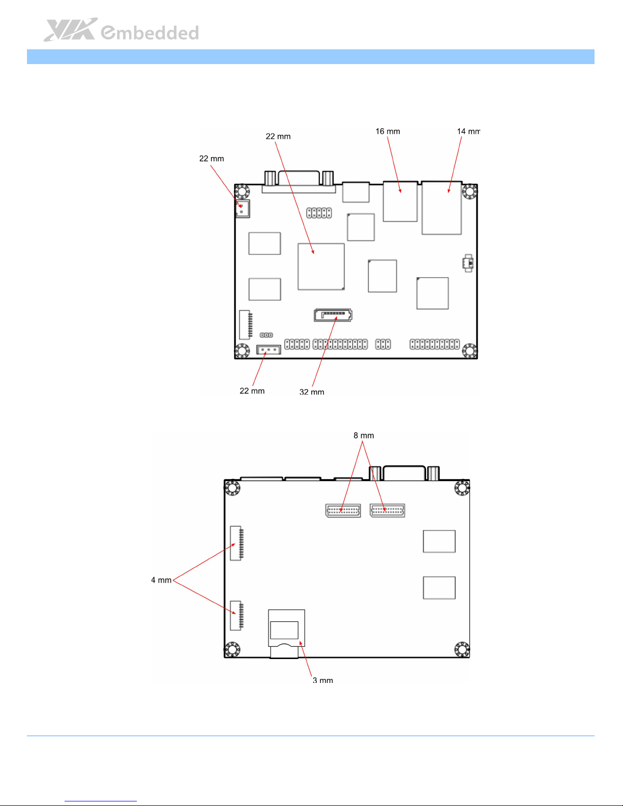
3.1.3. Suggested keepout areas
The figure below shows the areas of the mainboard that is highly suggested to
leave unobstructed.
Figure
Figure Figure
Figure 25
2525
25: Suggested keepout areas
: Suggested keepout areas: Suggested keepout areas
: Suggested keepout areas
Page 42

VAB
VABVAB
VAB----800
800800
800 User Manual
User ManualUser Manual
User Manual
34
3.2. Connection of Cables
VAB-800 is equipped with 4 cables, including DC-in X 1, COM X 1, Audio X 1,
USB/CAN X 1. The figure below shows the connection of these cables.
Figure
Figure Figure
Figure 26
2626
26: Connection of cables (top view)
: Connection of cables (top view): Connection of cables (top view)
: Connection of cables (top view)
Figure
Figure Figure
Figure 27
2727
27: Connection of cables (bottom view)
: Connection of cables (bottom view): Connection of cables (bottom view)
: Connection of cables (bottom view)
USB/CAN
Audio
COM
DC-in
COM (for debug only)
Page 43

VAB
VABVAB
VAB----800
800800
800 User Manual
User ManualUser Manual
User Manual
35
4.
4.4.
4. Making Ubuntu Demo Image
Making Ubuntu Demo ImageMaking Ubuntu Demo Image
Making Ubuntu Demo Image
This section describes how to evaluate the VAB-800 with Ubuntu image
downloaded from Freescale official web site.
Note:
Note:Note:
Note:
1. User should follow the Freescale’s policy to download the Ubuntu demo image from Freescale
official web site.
2. User should contact and follow Canonical’s policy for Ubuntu commercial usage or redistribution.
4.1. Getting Ubuntu demo image
1. Register your account at http://www.freescale.com/ to be able to
download the files.
2. Go to “Design Resources” item --> Software and Tools--> then click “All
Software and Tools”.
Page 44

VAB
VABVAB
VAB----800
800800
800 User Manual
User ManualUser Manual
User Manual
36
3. Go to “Featured Embedded Software and Tools”. Click the “i.MX Softward
and Development Tools”.
4. Go to “i.MX Development Boards and Systems by Device”. Click the
“i.MX53” plus sign to expand. Then click “i.MX53 Quick Start Board”.
Page 45

VAB
VABVAB
VAB----800
800800
800 User Manual
User ManualUser Manual
User Manual
37
5. Click “Downloads”.
There are development tools and prebuilt images shown here. You can select
Run-time Software to expand all items.
6. Download MX53_QSB_UBUNTU_SD_DEMO_IMAGE
http://www.freescale.com/webapp/sps/site/prod_summary.jsp?code=IMX53QSB&fpsp=1
http://www.freescale.com/webapp/sps/site/prod_summary.jsp?code=IMX53QSB&fpsp=1http://www.freescale.com/webapp/sps/site/prod_summary.jsp?code=IMX53QSB&fpsp=1
http://www.freescale.com/webapp/sps/site/prod_summary.jsp?code=IMX53QSB&fpsp=1
&tab=Design_Tools_Tab#
&tab=Design_Tools_Tab#&tab=Design_Tools_Tab#
&tab=Design_Tools_Tab#
User can get a zip file “MCIMX53-START-UBUNTU-11-09-Demo-Image.zip”.
Page 46

VAB
VABVAB
VAB----800
800800
800 User Manual
User ManualUser Manual
User Manual
38
4.2. Making demo image into Micro SD
1. Prepare a Micro SD storage card (at least 4 GB size and Class 4).
2. Refer to the document “MCIMX53-START-R Flashing Doc.pdf” after
unzipped. Follow the steps to make bootable Micro SD storage card.
4.3. Replace U-boot/Kernel/Modules of VAB-800
User has to replace u-boot, kernel and modules binary files which built from
VAB-800 BSP on the Micro SD storage card. These files can be found from EVK
folder.
1. Getting u-boot, kernel and modules.
User can get u-boot.bin, uImage and modules.tar.bz2 from EVK folder.
Table 2
Table 2Table 2
Table 2
Binary
BinaryBinary
Binary Description
DescriptionDescription
Description
uuuu----boot.bin
boot.binboot.bin
boot.bin U-Boot bootloader
uImage
uImageuImage
uImage Kernel
modules.tar.bz2
modules.tar.bz2modules.tar.bz2
modules.tar.bz2 Driver modules made through LTIB
vab
vabvab
vab----800_rootfs_patch.tar.bz2
800_rootfs_patch.tar.bz2800_rootfs_patch.tar.bz2
800_rootfs_patch.tar.bz2
Modifications configure files if user would like
to evaluate VAB-800 with Ubuntu
2. Copying the u-boot/uImage/driver modules.
2.1 Insert the Micro SD storage card which the OS has made by
“MCIMX53-START-R-BSP-11-09_C.exe” into your Linux developing PC.
2.2 Umount the Micro SD storage card if Linux OS auto mount your Micro
SD card.
The Micro SD card code name for this example is sdb1.
user@user:~ $ sudo umount /dev/sdb1
The path of EVK for this example is /home/user/EVK
Page 47

VAB
VABVAB
VAB----800
800800
800 User Manual
User ManualUser Manual
User Manual
39
2.3 Copy u-boot “u-boot.bin” to Micro SD storage card
user@user:~/EVK$ sudo dd if=./u-boot.bin of=/dev/sdb bs=512 seek=2
skip=2
2.4 Copy kernel “uImage” to Micro SD storage card
user@user:~/EVK$ sudo dd if=uImage of=/dev/sdb bs=512 seek=2048
2.5 Add driver modules of VAB-800
user@user:~/EVK$ sudo mount /dev/sdb1 /mnt
user@user:~/EVK$ sudo mkdir /mnt/mountpoint
user@user:~/EVK$ sudo cp ./modules.tar.bz2 /mnt/mountpoint/lib
user@user:~/EVK$ cd /mnt/mountpoint/lib
user@user:/mnt/mountpoint/lib$ sudo tar jxvf modules.tar.bz2
2.6 Put modification files in root file system
The configuration files should be modified for VAB-800. User can use files
“vab-800_rootfs_patch.tar.bz2” in EVK folder.
■ Unzip vab-800_rootfs_patch.tar.bz2
user@user:~/EVK$ sudo tar jxvf vab-800_rootfs_patch.tar.bz2
User will get the following files as shown below:
■ User runs the script “vab-800.sh” to copy modification files automatically.
user@user:~/EVK$ sudo ./vab-800.sh /mnt/mountpoint
user@user:~/EVK$ sudo sync && sync
user@user:~/EVK$ sudo umount /mnt
Now, unplug Micro SD storage card from your computer.
Page 48

VAB
VABVAB
VAB----800
800800
800 User Manual
User ManualUser Manual
User Manual
40
2.7 Boot from Micro SD storage card (on VAB-800)
■ Attach COM cable to VAB-800 COM2, and connect to your computer
■ To modify parameters in u-boot
To setup or modify u-boot parameters in u-boot:
[Display parts]
[Display parts][Display parts]
[Display parts]
setenv vga 'setenv bootargs console=ttymxc1,115200
video=mxcdi1fb:GBR24,VGA-XGA di1_primary vga'
setenv hdmi ‘setenv bootargs console=ttymxc1,115200
video=mxcdi0fb:RGB24,1024x768M@60 hdmi di0_primary’
setenv lvds1 ‘video=mxcdi0fb:RGB24,480C60 di0_primary ldb=di0
vga=off’
setenv lvds2 ‘video=mxcdi1fb:RGB24,480C60 di1_primary ldb=di1
vga=off’
[S
[S[S
[Storage
toragetorage
torage device parts]
device parts] device parts]
device parts]
setenv bootargs_mmc 'set bootargs ${bootargs} root=/dev/mmcblk1p1 rw
rootwait'
setenv bootargs_emmc ‘setenv bootargs ${bootargs}
root=/dev/mmcblk0p2 rootwait rw’
setenv bootcmd_emmc ‘run bootargs_base bootargs_emmc;fatload mmc 1
0x70800000 uImage;bootm’
Page 49

VAB
VABVAB
VAB----800
800800
800 User Manual
User ManualUser Manual
User Manual
41
[Boot s
[Boot s[Boot s
[Boot storage
toragetorage
torage device parts]
device parts] device parts]
device parts]
Here, user can set the boot device as either Micro SD or eMMC.
Set boot device as Micro SD:
setenv bootcmd ‘run bootcmd_mmc; bootm ${loadaddr}’
Set boot device as eMMC:
setenv bootcmd ‘run bootcmd_emmc; bootm ${loadaddr}’
[Others]
[Others][Others]
[Others]
setenv bootargs ‘console=ttymxc1,115200 gpu_nommu setenv bootargs
console=ttymxc1,115200 video=mxcdi0fb:RGB24,1920x1080M@60 hdmi
di0_primary root=/dev/nfs ip=dhcp
nfsroot=10.29.240.144:/tftpboot/rootfs,v3,tcp’
User has to save the parameters when completing the settings.
VAB-800 U-Boot > saveenv
VAB-800 U-Boot > boot
Finally, user should get the parameter in u-boot after modifying, type
command
pri
in u-boot. In the example: the display is VGA and boot from
Micro SD card.
baudrate=115200
loadaddr=0x70800000
netdev=eth0
ethprime=FEC0
uboot=u-boot.bin
kernel=uImage
ethact=FEC0
bootcd=run bootcmd_mmc
bootargs_nfs=setenv bootargs ${bootargs} root=/dev/nfs ip=dhcp
nfsroot=${serverip}:${nfsroot},v3,tcp
bootcmd_net=run bootargs_base bootargs_nfs; tftpboot ${loadaddr}
${kernel}; bootm
bootcmd_mmc=run bootargs_base bootargs_mmc; mmc read ${loadaddr}
0x800 0x1800; bootm
bootargs_mmc=set bootargs ${bootargs} root=/dev/mmcblk1p1 rw
rootwait
vga=setenv bootargs console=ttymxc1,115200 video=mxcdi1fb:GBR24,VGA-
Page 50

VAB
VABVAB
VAB----800
800800
800 User Manual
User ManualUser Manual
User Manual
42
XGA di1_primary vga
bootcmd_obds=ext2load mmc 0:1 0x70800000 /unit_tests/obds.bin; go
70800000
nfsroot=/tftpboot/rootfs
lcd=video=mxcdi0fb:RGB24,SEIKO-WVGA di0_primary
lvds=video=mxcdi0fb:RGB666,XGA di0_primary ldb=di0
lvds1=video=mxcdi0fb:RGB24,480C60 di0_primary ldb=di0 vga=off
lvds2=video=mxcdi1fb:RGB24,480C60 di1_primary ldb=di1 vga=off
bootcmd=run bootcmd_mmc; bootm ${loadaddr}
bootfile=uImage
bootargs=console=ttymxc1,115200 gpu_nommu setenv bootargs
console=ttymxc1,115200 video=mxcdi0fb:RGB24,1920x1080M@60 hdmi
di0_primary root=/dev/nfs ip=dhcp
nfsroot=10.29.240.144:/tftpboot/rootfs,v3,tcp
fileaddr=70800000
netmask=255.255.254.0
hdmi=setenv bootargs console=ttymxc1,115200
video=mxcdi0fb:RGB24,1024x768M@60 hdmi di0_primary
serverip=192.168.0.1
ipaddr=192.168.0.2
gatewayip=192.168.0.1
bootargs_base=setenv bootargs console=ttymxc1,115200 gpu_nommu
${vga}
dnsip=192.168.0.1
bootdelay=3
stdin=serial
stdout=serial
stderr=serial
Page 51

VAB
VABVAB
VAB----800
800800
800 User Manual
User ManualUser Manual
User Manual
43
4.4. Setting U-boot
1. Setting the display devices
[VGA]
[VGA][VGA]
[VGA]
To set VGA as display output
setenv bootargs_base ‘setenv bootargs console=ttymxc1,115200
gpu_nommu ${vga}’
To set VGA resolution
setenv vga 'setenv bootargs console=ttymxc1,115200
video=mxcdi1fb:GBR24,VGA-XGA di1_primary vga'
To replace the resolution, change the red color part with the desire resolution
mode.
For example: To set 1680 x 1050 resolution, change VGA-XGA with VGA-
WSXGA+:
setenv vga 'setenv bootargs console=ttymxc1,115200
video=mxcdi1fb:GBR24,VGA-WSXGA+ di1_primary vga'
There are four modes to be set in VAB-800:
VGA-WSXGA+ : 1680x1050p-60
VGA-SXGA : 1280x1024p-60
VGA-XGA : 1024x768p-60
VGA-SVGA : 800x600p-60
[HDMI]
[HDMI][HDMI]
[HDMI]
To set hdmi as display output
setenv bootargs_base ‘setenv bootargs console=ttymxc1,115200
gpu_nommu ${hdmi}’
Page 52

VAB
VABVAB
VAB----800
800800
800 User Manual
User ManualUser Manual
User Manual
44
To set HDMI resolution
setenv hdmi ‘setenv bootargs console=ttymxc1,115200
video=mxcdi0fb:RGB24,1024x768M@60 hdmi di0_primary’
To replace the resolution, change the red color part with the desire resolution
mode.
For example: To set 1920x1080, change 1024x768 with 1920x1080:
setenv hdmi ‘setenv bootargs console=ttymxc1,115200
video=mxcdi0fb:RGB24,1920x1080M@60 hdmi di0_primary’
[LVDS]
[LVDS][LVDS]
[LVDS]
To set LVDS as display output
setenv bootargs_base ‘setenv bootargs console=ttymxc1,115200
gpu_nommu ${lvds1}’
or
setenv bootargs_base ‘setenv bootargs console=ttymxc1,115200
gpu_nommu ${lvds2}’
To set LVDS port
setenv lvds1 ‘video=mxcdi0fb:RGB24,480C60 di0_primary ldb=di0
vga=off’
setenv lvds2 ‘video=mxcdi1fb:RGB24,480C60 di1_primary ldb=di1
vga=off’
VAB-800 support AUO 7” 800x480 LVDS panel in default.
2. Setting storage devices
[[[[Mic
MicMic
Micro SD
ro SD ro SD
ro SD storage
storagestorage
storage card
card card
card]]]]
setenv bootargs_mmc ‘set bootargs ${bootargs} root=/dev/mmcblk1p1 rw
rootwait’
setenv bootcmd_mmc ‘run bootargs_base bootargs_mmc; mmc read
${loadaddr} 0x800 0x1800; bootm’
Page 53

VAB
VABVAB
VAB----800
800800
800 User Manual
User ManualUser Manual
User Manual
45
[eMMC]
[eMMC][eMMC]
[eMMC]
setenv bootargs_emmc ‘setenv bootargs ${bootargs}
root=/dev/mmcblk0p2 rootwait rw’
setenv bootcmd_emmc ‘run bootargs_base bootargs_emmc;fatload mmc 1
0x70800000 uImage;bootm’
3. Setting booting storage devices
Here, user can set the boot device as either Micro SD or eMMC.
Set boot device as Micro SD:
setenv bootcmd ‘run bootcmd_mmc; bootm ${loadaddr}’
Set boot device as eMMC:
setenv bootcmd ‘run bootcmd_emmc; bootm ${loadaddr}’
4. Setting MAC address
Here, user can set the MAC address in u-boot. The address is on the Ethernet
physical port.
setenv ethaddr xx:xx:xx:xx:xx:xx
It is a must to reset after you set MAC address and save already:
saveenv
reset
Page 54

VAB
VABVAB
VAB----800
800800
800 User Manual
User ManualUser Manual
User Manual
46
4.5. Making demo image to eMMC (optional)
This section will guide user to copy images to eMMC for evaluation. However,
it is a must to finish first the section 4.2~4.3 before applying this section.
To make a demo image compression file, follow the steps below:
1. Getting u-boot, and kernel image.
User can directly get the u-boot.bin, and uImage from EVK folder.
TTTTable 3
able 3able 3
able 3
Binary Description
uuuu----boot.bin
boot.binboot.bin
boot.bin U-Boot bootloader Image
uImage
uImageuImage
uImage Linux Kernel Image
2. Making Ubuntu root file system
2.1 Insert the Micro SD storage card which the OS has made in section 4.3
on your Linux developing PC. (Ubuntu 10.04.x x86 at least)
2.2 Compress Micro SD storage card as a compression file.
The Micro SD card code name for this example is sdb1.
user@user:~ $ sudo mount /dev/sdb1 /mnt/mountpoint
user@user:~ $ cd /mnt/mountpoint
user@user: /mnt/mountpoint$ sudo tar jcvf ~/EVK/rootfs.tar.bz2 ./*
...
user@user: /mnt/mountpoint$ sudo sync && sync
user@user: /mnt/mountpoint$ cd ~
user@user:~ $ sudo umount /mnt/mountpoint
It would take 30~40 min to generate a “rootfs.tar.bz2”. User can uncompress it
into eMMC, and get an Ubuntu demo image.
3. Make demo image boot from eMMC.
Page 55

VAB
VABVAB
VAB----800
800800
800 User Manual
User ManualUser Manual
User Manual
47
Appendix A.
Appendix A.Appendix A.
Appendix A. Sta
StaSta
Starter Kit
rter Kitrter Kit
rter Kit
A.1. Starter Kit Assembly
The starter kit includes the following items:
1 x VAB-800
1 x VAB-800-A
1 x 7” LCD display with 4-wire resistive touch screen
1 x DC-in cable
1 x LVDS cable
1 x COM cable
To install the VAB-800-A to the VAB-800 mainboard, align and attach the
board-to-board connectors (J3, J1 & J2) on the bottom of VAB-800-A with the
pin headers (F_audio, J9 & J10 respectively) on the top of VAB-800 mainboard.
Figure
Figure Figure
Figure 28
2828
28: Connecting
: Connecting : Connecting
: Connecting VAB
VABVAB
VAB----800
800800
800----A to
A to A to
A to VAB
VABVAB
VAB----800
800800
800 mainboard
mainboard mainboard
mainboard
VAB
VABVAB
VAB----800
800800
800
VAB
VABVAB
VAB----800
800800
800----AAAA
Page 56

VAB
VABVAB
VAB----800
800800
800 User Manual
User ManualUser Manual
User Manual
48
The figure below shows the connection of panel.
Figure
Figure Figure
Figure 29
2929
29:
: :
: Connection of panel
Connection of panelConnection of panel
Connection of panel
Page 57

VAB
VABVAB
VAB----800
800800
800 User Manual
User ManualUser Manual
User Manual
49
A.2. VAB-800-A Specifications
Onboard I/O
Onboard I/OOnboard I/O
Onboard I/O
1 x I²C pin header
1 x DPIO pin header (4 Ins and 4 OUTS)
1 x 4-wire connector for the resistive touch screen
Back Panel I/O
Back Panel I/OBack Panel I/O
Back Panel I/O
1 x Stack type 3 ports audio I/O connector (support Line-out, Line-in and MIC-in)
1 x Power button
1 x Stack type 2 ports USB2.0 connector
1 x USBOTG connector for USB device
1 x Reset button
1 x Stack type 2 ports CAN D-sub connector
Form Factor
Form FactorForm Factor
Form Factor
4-layers
11.3 cm x 3.5 cm
Page 58

VAB
VABVAB
VAB----800
800800
800 User Manual
User ManualUser Manual
User Manual
50
A.3. VAB-800-A Layout
Figure
Figure Figure
Figure 30
3030
30:
: :
: VAB
VABVAB
VAB----800
800800
800----A
A A
A Layout (top view)
Layout (top view)Layout (top view)
Layout (top view)
Figure
Figure Figure
Figure 31
3131
31:
: :
: VAB
VABVAB
VAB----800
800800
800----A
A A
A Layout (b
Layout (bLayout (b
Layout (bottom view)
ottom view)ottom view)
ottom view)
CAN D-sub connector Reset button
USBOTG USB2.0
Power button
Audio I/O connector
4-wire connector DIO J_I²C3
J2 J1 J3
Page 59

VAB
VABVAB
VAB----800
800800
800 User Manual
User ManualUser Manual
User Manual
51
A.4. VAB-800-A Pinouts and Jumpers
DIO
Pin
PinPin
Pin Signal
SignalSignal
Signal Pin
PinPin
Pin Signal
SignalSignal
Signal
1 NC 2 -3 GPO_10 4 GPI_2
5 GPO_11 6 GPI_16
7 GPO_12 8 GPI_18
9 GPO_13 10 GPI_19
11 GND
J_I²C3
Pin
PinPin
Pin Signal
SignalSignal
Signal Pin
PinPin
Pin Signal
SignalSignal
Signal
1 I2C3_SCL 2 I2C3_SDA
3 GND
4-wire resistive touch
Pin
PinPin
Pin Signal
SignalSignal
Signal
1 TOPUCH_X+
2 TOPUCH_Y+
3 TOPUCH_X4 TOPUCH_Y-
Page 60

Page 61

VAB
VABVAB
VAB----800
800800
800 User Manual
User ManualUser Manual
User Manual
53
Appendix B.
Appendix B.Appendix B.
Appendix B. Mating Connector
Mating Connector Mating Connector
Mating Connector
Vendor Lists
Vendor ListsVendor Lists
Vendor Lists
The following table listed the mating connector vendor lists of VAB-800
mainboard.
Connectors
ConnectorsConnectors
Connectors
Vendor &
Vendor & Vendor &
Vendor & P/N
P/NP/N
P/N Mating Vendor & P/N
Mating Vendor & P/NMating Vendor & P/N
Mating Vendor & P/N
COM1 Neltron 1600R-XX-SM-TR JST SHR-10V-S-B
J9
Neltron 2208SM-XXG-EXX-XX-CR Samtec MMS-1XX-01-XX-DV series
J10
Neltron 2208SM-XXG-EXX-XX-CR Samtec MMS-1XX-01-XX-DV series
DC5V Neltron 2317SJ-XX-F4
JST
XHP-2
JTAG
Neltron 1600R-XX-SM-TR
JST
SHR-12V-S-B
LVDS ACES 87216-2416-06 ACES 87219-2400
Table
Table Table
Table 23
2323
23:
: :
: VAB
VABVAB
VAB----800
800800
800 mating connector vendor lists
mating connector vendor lists mating connector vendor lists
mating connector vendor lists
 Loading...