

Page 1

TRADEMARK
All products and company names are trademarks or registered
trademarks of their respective holders.
These specifications are subject to change without notice.
Manual Revision 2.1
May 27, 2004
User’User’
User’User’
User’
ss
ss
s
ManualManual
ManualManual
Manual
6000002P4MK21
VIA VIA
VIA VIA
VIA
P4M266AP4M266A
P4M266AP4M266A
P4M266A
mainboard mainboard
mainboard mainboard
mainboard
for Intel Socket 478 processorfor Intel Socket 478 processor
for Intel Socket 478 processorfor Intel Socket 478 processor
for Intel Socket 478 processor
Page 2

DISCLAIMER OF WARRANTIES:
THERE ARE NO WARRANTIES WHICH EXTEND BEYOND THE
DESCRIPTION ON THE FACE OF THE MANUFACTURER LIMITED
WARRANTY. THE MANUFACTURER EXPRESSLY EXCLUDES ALL
OTHER WARRANTIES, EXPRESS OR IMPLIED, REGARDING ITS
PRODUCTS; INCLUDING ANY IMPLIED WARRANTIES OF
MERCHANTABILITY, FITNESS FOR A PARTICULAR PURPOSE OR
NONINFRINGEMENT. THIS DISCLAIMER OF WARRANTIES SHALL
APPLY TO THE EXTENT ALLOWED UNDER LOCAL LAWS IN THE
COUNTRY PURCHASED IN WHICH LOCAL LAWS DO NOT ALLOW
OR LIMIT THE EXCLUSION OF THE IMPLIED WARRANTIES.
Page 3

Table of Contents
Section 1 Introduction
Package Contents ...................................................... 1-1
System Block Diagram ............................................... 1-2
Section 2 Features
Mainboard Features ................................................... 2-1
Section 3 Installation
Mainboard Layout ..................................................... 3-2
Easy Installation Procedure
Jumper Settings .......................................................... 3-3
System Memory Configuration .................................. 3-4
Device Connectors..................................................... 3-5
External Modem Ring-in Power ON and
Keyboard Power ON Function (KBPO) ..................... 3-10
Section 4 BIOS Setup
Main Menu ................................................................ 4-1
Standard CMOS Setup ............................................... 4-2
Advanced BIOS Features .......................................... 4-3
Advanced Chipset Features ...................................... 4-6
Integrated Peripherals ................................................ 4-11
Power Management Setup ......................................... 4-16
PNP/PCI Configuration Setup .................................... 4-19
PC Health Status ........................................................ 4-21
Power BIOS Features ................................................. 4-22
Defaults Menu ........................................................... 4-24
Supervisor/User Password Setting ............................ 4-25
Exit Selecting .............................................................. 4-26
Page
Page 4

Section 5 Driver Installation
Easy Driver Installation .............................................. 5-1
Appendix Appendix A
Update Your System BIOS ......................................... A-1
Page
Page 5
Introduction
Page 1-1
B
A
C
D
USER’S
MANUAL
E
F
G
H
Section 1
INTRODUCTION
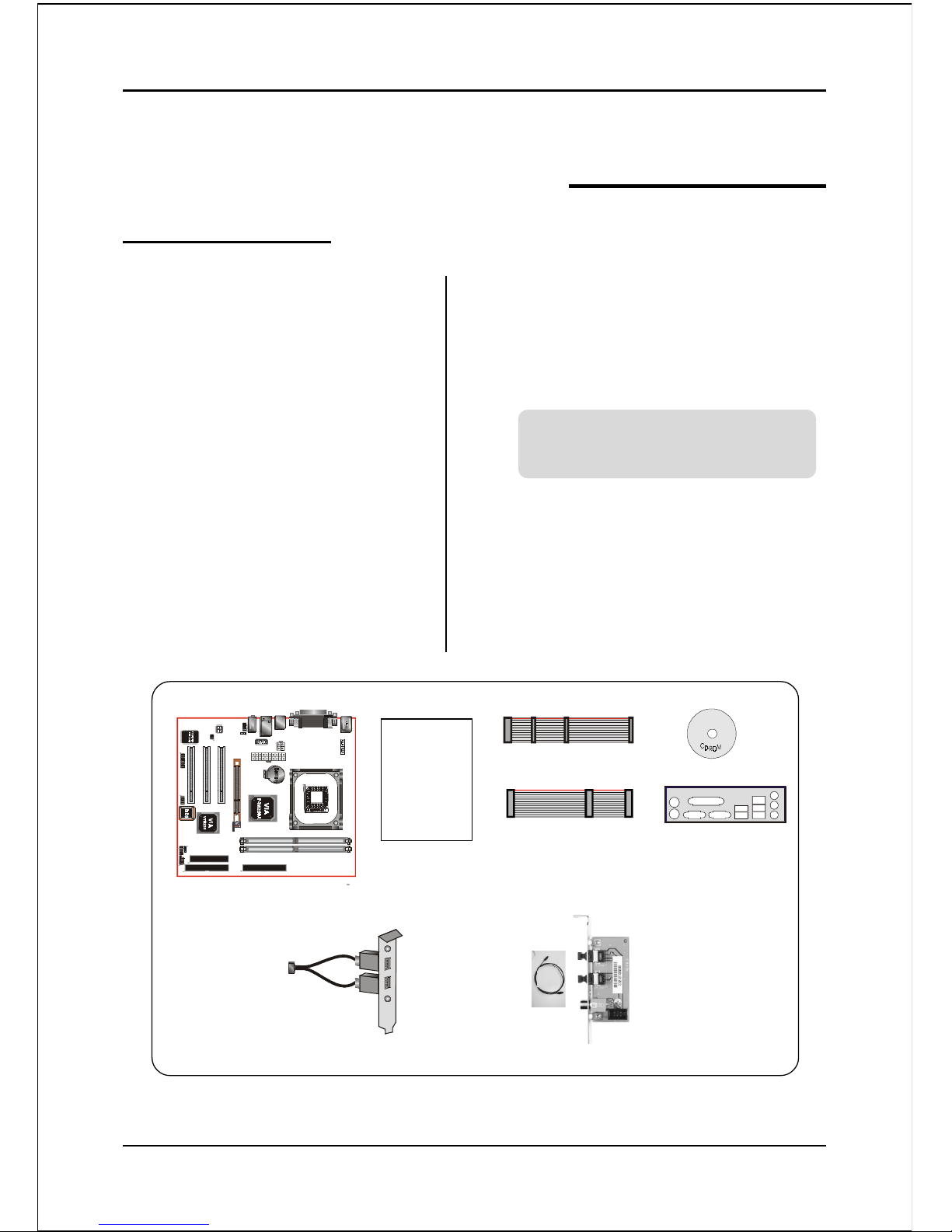
Package Contents
Contents
A. Mainboard
B. User’s manual
C. Floppy drive cable
D. HDD drive cable
E. CD (drivers and utilities)
F. I/O Shield
Optional Items
G. Extra USB2.0 port cable
H. S/PDIF Module
If you need the optional item, please
contact your dealer for assistance.
Page 6

Introduction
Page 1-2
Figure 2: System Block Diagram
System Block Diagram
Page 7

Features
Page 2-1
Section 2
FEATURES
Mainboard Features
Processor
Socket 478 Intel® Pentium® 4 processor with 533MHz front side bus up to
3.0+ GHz
Socket 478 Intel®Celeron processor with 400MHz front side bus up to 2.4 GHz
Chipset
VIA P4M266A AGPset : VIA P4M266A + VT8235
- Built-in VIA ProSavage 8 Graphics core
Main Memory
Two 184-pin DDR DIMM sockets for 64-bit, Unbuffered, Single/Double-
side and Non-ECC DDR-200/266 DIMMs
Supports up to 2GB memory size
BIOS
Flash EEPROM with Award BIOS
- ACPI v2.0 compliant
- S3 (Suspend to DRAM) sleep-state support (Optional)
- SMBIOS (System Management BIOS) v2.2 compliant
- Supports Power failure recovery
- Able to wake the computer from specific states by Power switch, RTC alarm,
USB, PS2 KB&Mouse, Modem ring on COM#1…
Onboard PCI Devices
LAN --> Embedded 10/100Mbps Fast Ethernet controller with onboard
VIA 6103 PHY
Page 8

Features
Page 2-2
IDE --> Embedded IDE controller with 2 ordinary IDE ports up to 4 IDE
devices, supports ATA-133 with up to 133MB/sec bandwidth
Legacy IO Controller
ITE 8705 LPC IO controller for floppy, printer, serial, game and CIR/SIR
interface
Audio
Six channel audio with analog and digital output
- AC’97 v2.3 compliant
- In 2-CH mode, supports Line-In (Light blue), Line-Out (Lime) and Mic-In
(Pink) at rear panel
- In 6-CH mode, supports Rear speaker out (Light blue), Front speaker out
(Lime) and Center&Subwoofer speaker out (Pink) at rear panel
- Supports CD-In and S/PDIF-in/out interface
- Supports Line-out and Mic-In for front panel
Peripheral Interfaces
) At Rear Panel
PS/2 keyboard and mouse ports
One Parallel (printer) port
One Serial port
One VGA port
One RJ45 LAN connector
Four USB2.0 ports
Three Audio jacks
) Onboard connector and pin-header
One floppy drive connector
Two IDE connectors
Two extra USB2.0 ports
One CD-IN connector
Page 9

Features
Page 2-3
One S/PDIF in/out connector
One IR connector
One Front Panel Audio connector
One Game port connector
Two Fan connectors
Front Panel Controller
Supports Reset & Soft-Off switches
Supports HDD & Power LEDs
Supports PC speaker
Expansion Slots
One AGP slot supporting 1.5v 4X AGP cards
- AGP v2.0 compliant
Three PCI slots with Bus Master support
- PCI v2.2 compliant
Other Features
Magic Health – a BIOS H/W monitoring utility for voltage, temperature and
fan-speed sensing displayed during POST
EZ Boot – A simple shortcut to select the boot device, e.g. hard drive, CD-
ROM or floppy without entering CMOS setup
Supports exclusive KBPO (Keyboard Power On) function
Excellent Over clocking capabilities through
- subtle frequency tuning on FSB
- supports complete Asynchronous FSB/Memory for overclocking
Form Factor
210mm x 245 mm Micro ATX size
Page 10

Features
Page 2-4
Page 11

Installation
Page 3-1
Section 3
INSTALLATION
Page 12

Installation
Page 3-2
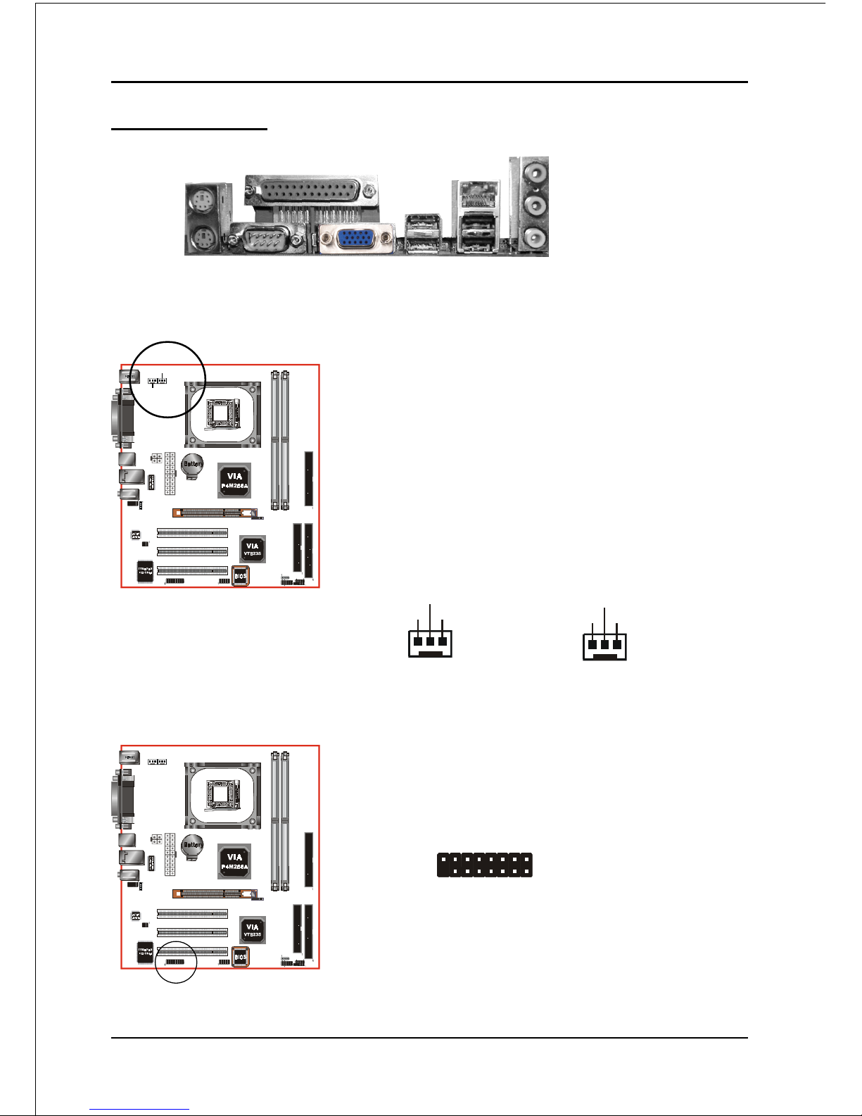
Mainboard Layout
Page 13

Installation
Page 3-3
3-1 Jumper Settings
JCMOS:
Settings:
1-2: Normal (Default)
2-3: Clear CMOS
1
Clear CMOS data Jumper
If the CMOS data becomes corrupted or you
forgot the supervisor or user password,
clear the CMOS data to reconfigure the
system back to the default values stored in
the ROM BIOS.
To CMOS Clear data, please follow the steps below.
1. Turn off the system.
2. Change the jumper from “1-2” to “2-3” position
for a few seconds.
3. Replace the jumper on to the “1-2” position.
4. Turn on the system and hold down the <Del>
key to enter BIOS setup.
Page 14

Installation
Page 3-4
NOTES:
• Using non-compliant memory with higher bus speeds
(overclocking) may severely compromise the integrity of the
system.
<Figure 1>
<Table 1>
3-2 System Memory Configuration
Memory Layout
The mainboard accommodates two PC1600/PC2100 184-pin DIMMs (Dual In-line
Memory Modules):
• Supports up to 2.0GB of 200/266MHz DDR SDRAM
• Supports unbuffered and non-ECC DIMMs
• Supports configurations defined in the JEDEC DDR DIMM specification
Figure 1 and Table 1 show two possible memory configurations.
DDR DIMM 1
DDR DIMM 2
yromeMlatoT
1MMIDRDD 2MMIDRDD
BG1=
mumixaM
*MARDSRDD
,BM215,BM652,BM821,BM46
1X*BG1
enoN
BG2=
mumixaM
*MARDSRDD
,BM215,BM652,BM821,BM46
1X*BG1
*MARDSRDD
,BM215,BM652,BM821,BM46
1X*BG1
Page 15
Installation
Page 3-5
JCPU_FAN / JSYS_FAN:
CPU/Chassis Fan Power Connectors
JCPU_FAN: The CPU must be kept cool by using a
heatsink with fan assembly.
JSYS_FAN: The chassis fan will provide adequate
airflow throughout the chassis to prevent overheating the CPU.
JCPU_FAN
Figure 2 - I/O Ports
3-3 Connectors
JCPU_FAN
Ground
+12V
Sence
JSYS_FAN
JSYS_FAN
1
2
GAME1: Game/MIDI connector
This port works well with any application that is
compatible with the standard PC joystick.
Ground
+12V
Sence
COM1
Parallel Port
VGA1
RJ-45 LAN
USB2.0
ports
USB2.0
ports
PS/2
Mouse
PS/2
Keyboard
Mic-in/Center&Subwoofer (Pink)
Line-out/Front out (Lime)
Line-in/Rear out (Light blue)
Page 16

Installation
Page 3-6
PW1
PW12
PW1: 20-pin ATX Power Connector
PW12: 4-pin ATX12V Power Connector
The mainboard is equipped with a standard 20-pin
ATX main power connector and a 4-pin +12V
power connector for connecting an ATX12V
power supply. The plugs of the power cables are
designed to fit in only one orientation. Find the
proper orientation then insert the plugs into the
connectors until they fit in place.
Caution:
The PW1 and PW12 Power Connector must be used simultaneously
or else this system will not boot-up.
40 39
2
1
IDE1/IDE2
34 33
2
1
FDD
The board requires a minimum of 250 Watt power
supply to operate. Your system configuration (amount
of memory, add-in cards, peripherals, etc.) may
exceed this minimum power requirement. To ensure
that adequate power is provided, use a 300 Watt or
greater power supply.
1
3
1
-12V3.3V
Ground+5V
PS-ON+5V
-5VPW-OK
+5V5VSB
+5V+12V
+12V+12V
10
11
4
2
3.3V3.3V
GroundGround
GroundGround
GroundGrou nd
GroundGround
20
PW1
PW12
IDE1
IDE2
FDD
FDD: Floppy Controller Connector
This mainboard is equipped with a floppy disk drive
connector for connecting up to 2 floppy disk drives.
IDE1/IDE2: Ultra DMA-66/100/133 Primary/Secondary
IDE Connector
This mainboard is equipped with 2 IDE disk connec-
tors for connecting up to 4 ATA-133 IDE drives.
It supports PIO and DMA mode operations for
maximum data transfer rate of 133MB/sec per channel.
When use two IDE drives, one must be set to Master
mode and the other one to Slave mode. Refer to your
disk drive user’s manual for information about selecting the proper drive switch settings.
Page 17

Installation
Page 3-7
Settings
Pins (5-6) & (9-10) Short (default): Only the onboard rear
panel audio jack can be used.
Pins (5-6) & (9-10) Open: Only front panel audio jack can
be used.
CFPA: Front Panel Audio Connector
When the jumpers are removed this connector
can be used for front panel audio.
The front panel line-out phone jack should
have a “normal close” switch . Without a
phone- plug inserted, the rear panel audio is
enabled. With phone plug inserted, the rear
panel audio will be disabled.
In 2-Channel audio mode, Mic-In is shared for both front panel and rear panel.
In 6-Channel audio mode, the Mic-In is dedicated for front panel use, and rear
panel Mic-In function will switch to Center and Subwoofer support.
1
Rear Line-out-FR
Front Line-out-R
Rear Line-out-FL
Front Line-out-L
MIC_In
NC
+5V
Key
9
2
10
GND
CD-IN: CD Audio_IN Connector
The CD-IN connector is for receiving audio form a
CD-ROM drive, TV tuner or MPEG card.
CD_IN_Left
1
CD_IN_Right
CD_Reference
CD-IN
Page 18

Installation
Page 3-8
S/PDIF: Sony/Philips Digital InterFace connector
This connector links digital audio between the
mainboard and your audio devices, such as CD
player, sampler or DAT recorder. It allows the
digital transmission of audio data in S/PDIF format.
1
5
2
6
VCC
NC
GND
SPDIF_IN
SPDIF_OUT
CUSB3: Two USB 2.0 ports
This mainboard includes 2 additional onboard USB
ports, identified by two 10-pin connector.
If you wish to use the additional USB ports, install
the card-edge bracket to the system chassis then
insert its cables to this 10-pin connector.
USB2.0 allows data transfer speed up to 480Mbps.
CUSB3
CAUTION !
Please make sure the USB cable has the same
pin assignment. A different pin assignment
may cause damage to the system.
If you need the USB cable, please contact our
retailer.
Page 19

Installation
Page 3-9
CFP / CIR / CSPK
CFP: Front Panel Connector
HD_LED
This LED will light up whenever the hard drive
is being accessed.
PWR_LED
This connects to the power button of the
system chassis
RST
This switch allows you to reboot without
having to power off the system thus prolonging
the life of the power supply or system.
PW_ON
This is connected to the power button on the
case. Using the Soft-Off by Pwr-BTTN feature,
you can choose either Instant Off (turn off
system immediately) or 4 sec delay (push the
button for 4 seconds to turn off the system).
When the system is in 4 sec delay mode,
suspend mode is enabled by pushing the
button momentarily.
CIR: IR connector
Connect your IrDA cable to this IR connector.
1. VCC 4. GND
2. NC 5. IRTX
3. IRRX
CSPK: Speaker
Connect to the system’s speaker for beeping
1. VCC 3. GND
2. NC 4. Speaker
Page 20

Installation
Page 3-10
NOTES:
• Intel ATX version 2.0 specification recommends a power supply that
supplies >=2.0 A in 5.0 VSB. However, this mainboard supports a 5.0
VSB standby power supply > = 2A .
• We recommend you use the power supply with 2.0 A in 5.0 VSB, which
supports PCI 2.3 specification for remote power-on and wake-up
functions.
3-4 External Modem Ring-in Power ON and
Keyboard Power ON Functions (KBPO)
Modem-Ring Power ON Function
The I/O chipset provides the two serial ports with the External Modem Ring-in Power
ON function. Once you connect an external modem to COM1 or COM2, the
mainboard enables you to turn on the system through remote and host dial-up
control.
Keyboard Power ON Function
The mainboard features a keyboard power on function that enables you to turn on
the power supply using a keypress. Follow these instructions to enable the Key-
board Power ON function .
Step : Use the Keyboard Power ON function (KBPO) to turn on the system by using
a key press, password, or hot key combination etc. as set in the BIOS Power
Management Setup menu (refer to the BIOS Power Management Setup for
details). The BIOS default setting is keyboard Hot key (<Ctrl> + <F1>). To power
off the system, use the Soft-OFF function under Windows XP/ME/2000/98.
(refer to Windows online help).
Page 21

BIOS
Page 4-1
Section 4
BIOS SETUP
Main Menu
The ROM BIOS provides a built-in Setup program which allows user to modify the
basic system configuration and hardware parameters. The modified data is stored in
a battery-backed CMOS, so that data will be retained even when the power is turned
off. In general, the information saved in the CMOS RAM will stay unchanged unless
there is a configuration change in the system, such as hard drive replacement or a
device is added.
It is possible for the CMOS battery to fail causing CMOS data loss. If this happens
you will need install a new CMOS battery and reconfigure your BIOS settings.
The BIOS setup screen and description are for reference only, and may
not exactly match what you see on your screen. The contents of BIOS are
subject to change without notice. Please visit our website for updates.
To enter the Setup Program :
Power on the computer and press the <Del> key during the POST (Power On Self
Test). The BIOS CMOS SETUP UTILITY opens.
Figure 1: CMOS Setup Utility
Page 22

BIOS
Page 4-2
The main menu displays all the major selection items. Select the item you need to
reconfigure. The selection is made by moving the cursor (press any direction (arrow
key ) to the item and pressing the ‘Enter’ key. An on-line help message is displayed
at the bottom of the screen as the cursor is moved to various items which provides a
better understanding of each function. When a selection is made, the menu of the
selected item will appear so that the user can modify associated configuration
parameters.
4-1 Standard CMOS Setup
Choose “STANDARD CMOS FEATURES” in the CMOS SETUP UTILITY Menu
(Figure 2). Standard CMOS Features Setup allows the user to configure system
settings such as the current date and time, type of hard disk drive installed, floppy
drive type, and display type. Memory size is auto-detected by the BIOS and
displayed for your reference. When a field is highlighted (use direction keys to move
the cursor and the <Enter> key to select), the entries in the field can be changed by
pressing the <PgDn> or the <PgUp> key.
Figure 2: Standard CMOS Setup
Notes: • If the hard disk Primary Master/Slave and Secondary Master/Slave are set to Auto,
the hard disk size and model will be auto-detected.
• The “Halt On:” field is used to determine when the BIOS will halt the system if an
error occurs.
Page 23

BIOS
Page 4-3
4-2 Advanced BIOS Features
Selecting the “ADVANCED BIOS FEATURES” option in the CMOS SETUP UTILITY
menu allows users to change system related parameters in the displayed menu. This
menu shows all of the manufacturer’s default values for the board.
Pressing the [F1] key displays a help message for the selected item.
Figure 3: BIOS Features Setup
Hard Disk Boot Priority
This item allows you to select the hard disk boot priority.
Virus Warning
During and after system boot up, any attempt to write to the boot sector or partition
table of the hard disk drive halts the system and an error message appears.
You should then run an anti-virus program to locate the virus. Keep in mind that this
feature protects only the boot sector, not the entire hard drive.
Enabled: Activates automatically when the system boots up causing a warning
message to appear when anything attempts to access the boot sector.
Disabled: No warning message appears when anything attempts to access the boot
sector.
Note: Many disk diagnostic programs that access the boot sector table can
trigger the virus warning message. If you plan to run such a program, we
recommend that you first disable the virus warning.
Page 24

BIOS
Page 4-4
CPU L1 & L2 Cache
This controls the status of the processor’s internal and external (L2) cache area.
Options: Enabled, Disabled.
CPU L2 Cache ECC Checking
This item allows you to enable/disable CPU L2 Cache ECC checking.
Options: Enabled, Disabled.
Quick Power On Self Test
This category speeds up the Power On Self Test (POST). The default is Enabled.
Enabled: This setting will shorten or skip of the items checked during POST.
Disabled: Normal POST.
First /Second/Third/Other Boot Device
The BIOS attempts to load the operating system from the devices in the sequence
selected in these items.
Options: Floppy, LS120, HDD-0, SCSI, CDROM, HDD-1, HDD-2, HDD-3, ZIP100,
USB-FDD, USB-ZIP, USB-CDROM, USB-HDD, LAN, Disabled.
Boot Other Device
When enabled, the system searches all other possible locations for an operating
system if it fails to find one in the devices specified under the first, second, and third
boot devices.
Options: Enabled, Disabled.
Swap Floppy Drive
This will swap your physical drive letters A & B if you are using two floppy disks.
Options: Enabled, Disabled.
Boot Up Floppy Seek
If this item is enabled, it checks the size of the floppy disk drives at start-up time.
You don’t need to enable this item unless you have a legacy diskette drive with
360K capacity.
Options: Enabled, Disabled.
Boot Up NumLock Status
This controls the state of the NumLock key when the system boots. The default is On.
On: The keypad acts as a 10-key pad.
Off: The keypad acts like cursor keys.
Page 25

BIOS
Page 4-5
Typematic Rate Setting
This determines the keystrokes repeat rate. The default is Disabled.
Enabled: Allows typematic rate and typematic delay programming.
Disabled: The typematic rate and typematic delay will be controlled by the keyboard
controller in your system.
Typematic Rate (Chars/Sec)
This is the number of characters that will be repeated by a keyboard press.
The default is 6.
Options: 6 ~ 30 characters per second.
Typematic Delay (msec)
This setting controls the time between the first and the second character displayed
by typematic auto-repeat. The default is 250.
Options: 250/500/750/1000 msec.
Security Option
This category allows you to limit access to the System and Setup, or just to Setup.
The default is Setup.
System: The system will not boot and the access to Setup will be denied if the
correct password is not entered at the prompt.
Setup: The system will boot; but the access to Setup will be denied if the
incorrect password is not entered at the prompt.
OS Select For DRAM > 64 MB
Some operating systems require special handling. Use this option only if your
system has greater than 64 MB of memory. The default is Non-OS2.
OS2: Select this if you are running the OS/2 operating system with greater
than 64 MB of RAM.
Non-OS2: Select this for all other operating systems and configurations.
Small Logo (EPA) Show
If the BIOS contains an internal bitmap picture, this option sets the bitmap display at
the top right corner of the screen.
Options: Enabled, Disabled.
Page 26

BIOS
Page 4-6
4-3 Advanced Chipset Features
Choose the “ADVANCED CHIPSET FEATURES” option in the CMOS SETUP
UTILITY menu to display following menu.
Figure 4: Chipset Features Setup
System BIOS Cacheable
This item allows the system to be cached in memory for faster execution.
Options: Disabled, Enabled.
Delay Prior to Thermal
Set this item to enable the CPU Thermal function to engage after the specified time.
The default is 16 minutes.
Options: 4, 8, 16, 32 minutes.
VGA Share Memory Size
This item allows you to select the VGA share memory size for video.
Options: 8M, 16M, 32M, Disabled.
Page 27

BIOS
Page 4-7
DRAM Clock / Drive Control
Scroll to DRAM Clock/Drive Control and press <Enter>. The following screen
appears:
Current FSB Frequency
Display the current CPU front side bus frequency information.
Current DRAM Frequency
Display the current DRAM frequency information.
DRAM Clock
This item allows you to select DRAM clock.
Options: By SPD, 100MHz, 133MHz.
DRAM Timing
For setting DRAM Timing select By SPD to follow SDRAM Serial Presence Detect
Specification.
Options: Manual, Auto by SPD.
DRAM CAS Latency
Enables you to select the CAS latency time. The value is set at the factory depending
on the DRAM installed. Do not change the values in this field unless you change
specifications of the installed DRAM and DRAM clock from DRAM Timing Selectable.
The default is set by SPD (see ‘DRAM Timing’).
Options: 2, 2.5.
Bank Interleave
The item allows you to set how many banks of SDRAM support in your mainboard.
Default is by SPD.
Options: 2 Bank, 4 Bank, Disabled.
Page 28

BIOS
Page 4-8
Precharge to Active (Trp)
This item refers to the number of cycles required to return data to its original
location to close the bank or the number of cycles required to page memory before
the next bank activate command can be issued. The default is by DRAM SPD.
Options: 3T, 2T.
Active to Precharge (Tras)
This item sets the minimum RAS pulse width. The default is by DRAM SPD.
Options: 5T, 6T.
Active to CMD (Trcd)
This item sets the timing parameters for the system memory such as the CAS (Column
Address Strobe) and RAS (Row Address Strobe). The default is by DRAM SPD.
Options: 3T, 2T.
DRAM Command Rate
Setup the timing at each cycle.
Options: 1T Command, 2T Command.
Page 29

BIOS
Page 4-9
AGP & P2P Bridge Control
Scroll to AGP & P2P Bridge Control and press <Enter>. The following screen appears:
AGP Aperture Size (MB)
This item defines the size of the aperture if you use an AGP graphics adapter. It
refers to a section of the PCI memory address range used for graphics memory.
Options: 4M, 8M, 16M, 32M, 64M, 128M, 256M.
AGP Mode
Chipset AGP Mode support.
Options: 1X, 2X, 4X.
AGP Driving Control
This item allows you to adjust the AGP driving force. Choose Manual to key in a
AGP Driving Value in the next selection. This field is recommended to set in Auto for
avoiding any error in your system.
Options: Auto, Manual.
AGP Fast Write
Selecting Enabled allows to use Fast Write Protocol for 4X AGP card.
Options: Enabled, Disabled.
AGP Master 1 WS Write
When Enabled, Writes to the AGP (Accelerated Graphics Port) are executed with one
wait states.
Options: Enabled, Disabled.
AGP Master 1 WS Read
When Enabled, Reads to the AGP (Accelerated Graphics Port) are executed with one
wait states.
Options: Enabled, Disabled.
Page 30

BIOS
Page 4-10
CPU & PCI Bus Control
Scroll to CPU & PCI Bus Control and press <Enter>. The following screen
appears:
CPU to PCI Write Buffer
When enabled, up to four words of data can be written to the PCI bus without interruting
the CPU. When disabled, a write buffer is not used and the CPU read cycle will not be
completed until the PCI bus signals that it is ready to receive the data.
Options: Enabled, Disabled.
PCI Master 0 WS Write
When Enabled, Writes to the PCI bus are commanded with zero wait states.
Options: Enabled, Disabled.
PCI Delay Transaction
The chipset has an embedded 32-bit posted write buffer to support delay transactions
cycles. Select Enabled to support compliance with PCI specification version 2.3.
Options: Enabled, Disabled.
Page 31

BIOS
Page 4-11
4-4 Integrated Peripherals
Figure 5: Integrated Peripherals
Init Display First
If two video cards are used (1 AGP and 1 PCI) this specifies which one will be the
primary display adapter. The default is PCI Slot.
Options: PCI Slot, AGP.
VIA OnChip IDE Device
Scroll to VIA Onchip IDE Device and press <Enter>. The following screen appears:
IDE DMA transfer access
Automatic data transfer between system memory and IDE device with minimum CPU
intervention. This improves data throughput and frees CPU to perform other tasks.
Options: Enabled, Disabled.
Page 32

BIOS
Page 4-12
OnChip IDE Channel0/1
The integrated peripheral controller contains an IDE interface with support for two
IDE channels. Select “Enabled” to activate each channel separately.
Options: Enabled, Disabled.
Note: If you do not use the onboard IDE connector, then you will need to set the
Onboard Primary PCI IDE and Onboard Secondary PCI IDE to “Disabled”.
IDE Prefetch Mode
Selecting “Enabled” reduces latency between each drive read/write cycle, but may
cause instability in IDE subsystems that cannot support such fast performance. If
you are getting disk drive errors, try setting this value to Disabled. This field does
not appear when the Internal PCI/IDE field, above, is Disabled.
Options: Enabled, Disabled.
Primary/Secondary Master/Slave PIO
The four IDE PIO (Programmed Input/Output) fields let you set a PIO mode (0-4) for
each of the four IDE devices that the onboard IDE interface supports. Modes 0 to 4
provide successively increased performance. In Auto mode, the system automati-
cally determines the best mode for each device.
Options: Auto, Mode 0 ~ 4.
Primary/Secondary Master/Slave UDMA
Select the mode of operation for the IDE drive. Ultra DMA-33/66/100/133 implemen-
tation is possible only if your IDE hard drive supports it and the operating environ-
ment includes a DMA driver. If your hard drive and your system software both
support Ultra DMA-33/66/100/133, select Auto to enable UDMA mode by BIOS.
Options: Auto, Disabled.
IDE HDD Block Mode
Block mode is also called block transfer, multiple commands, or multiple sector read/
write. If your IDE hard drive supports block mode (most new drives do), select
Enabled for automatic detection of the optimal number of block read/writes per
sector the drive can support.
Options: Enabled, Disabled.
Page 33

BIOS
Page 4-13
VIA Onchip PCI Device
Scroll to VIA Onchip PCI Device and press <Enter>. The following screen appears:
VIA-3058 AC97 Audio
This item allows you to disable the chipset on-chip support for AC97 Audio.
Options: Auto, Disabled.
VIA-3043 Onchip LAN (Optional)
Enables the onboard LAN feature.
Options: Auto, Disabled.
VIA-6102 MAC Address (Optional)
Allows you to input the VIA-6102 MAC address.
Onboard Lan Boot ROM (Optional)
Enable/disable the onboard LAN Boot ROM.
Options: Enabled, Disabled.
Onchip USB Controller
Enables the USB controller.
Options: All Enabled, All Disabled, 1&2 USB Port, 2&3 USB Port, 1&3 USB Port, 1
USB Port, 2 USB Port, 3 USB Port.
Onchip EHCI Controller
Enables the EHCI (USB2.0) controller.
Options: Enabled, Disabled.
USB Keyboard Support
Enable/disable support for USB keyboard.
Options: Enabled, Disabled.
USB Mouse Support
Enable/disable support for USB mouse.
Options: Enabled, Disabled.
Page 34

BIOS
Page 4-14
Super IO Chip Setup
Scroll to Super IO Chip Setup and press <Enter>. The following screen appears:
Onboard FDC Controller
Select Enabled if your system has a floppy disk controller (FDC) installed on the
system board and you wish to use it. If you install add-in FDC or the system has no
floppy drive, select Disabled in this field.
Options: Enabled, Disabled.
Onboard Serial Port 1
Select an address and corresponding interrupt for the first serial port.
Options: 3F8/IRQ4, 2E8/IRQ3, 3E8/IRQ4, 2F8/IRQ3, Disabled, Auto.
Infrared Port Select
Select an address for Infrared port.
Options: 3F8/IRQ4, 2E8/IRQ3, 3E8/IRQ4, 2F8/IRQ3, Disabled, Auto.
UR2 Duplex Mode
This item allows you to select IR half/full duplex function.
Options: Half, Full.
Onboard Parallel Port
This field allows the user to configure the LPT port.
Options: 378/IRQ7, 278/IRQ5, 3BC/IRQ7, Disabled.
Parallel Port Mode
This field allows the user to select the parallel port mode.
Options: SPP, EPP, ECP, ECP+EPP.
ECP Mode USE DMA
This field allows the user to select DMA1 or DMA3 for the ECP mode.
Options: DMA1, DMA3.
Page 35

BIOS
Page 4-15
Game Port Address
Select an address for the Game port.
Options: 201, 209, Disabled.
Midi Port Address
Select an address for the Midi port.
Options: 300, 330, Disabled.
Midi Port IRQ
Select an interrupt for the Midi port.
Options: 5, 10.
Page 36

BIOS
Page 4-16
4-5 Power Management Setup
Choose the “POWER MANAGEMENT SETUP” in the CMOS SETUP UTILITY to
display the following screen. This menu allows the user to modify the power
management parameters and IRQ signals. In general, these parameters should not be
changed unless it’s absolutely necessary.
Figure 6: Power Management
ACPI Function
This option allows you to select ACPI Function.
Options: Enabled, Disabled.
ACPI Suspend Type (Optional)
This item allows you to select S1(Power-On-Suspend) or S3(Suspend-To-RAM)
function. When set to “S3(STR)” or “S1&S3” the following two fields become
available.
Options: S1(POS), S3(STR), S1&S3.
Power Management Option
Use this to select your Power Management selection.
Max. saving: Maximum power savings. Inactivity period is 1 minute in each mode.
Min. saving: Minimum power savings. Inactivity period is 1 hour in each mode.
User define: Allows user to define PM Timers parameters to control power saving
mode.
Page 37

BIOS
Page 4-17
HDD Power Down
Powers down the hard disk drive after a preset period of system inactivity.
Options: Disabled, 1 ~ 15 Min.
Suspend Mode
Automatically, shuts off all devices except the CPU after a preset period of system
inactivity.
Options: Disabled, 1 , 2, 4 ,6, 8, 10, 20, 30, 40 min and 1 hour .
Video Off Option
When enabled, this feature allows the VGA adapter to operate in a power saving mode.
Always On: Monitor will remain on during power saving modes.
Suspend->Off: Monitor blanked when the systems enters the suspend mode.
Video Off Method
This option allows you to select how the video will be disabled by the power
management. The default is V/H Sync + Blank
V/H Sync + Blank: System turns off vertical and horizontal synchronization ports
and writes blanks to the video buffer.
DPMS Support: Select this option if your monitor supports the Display Power
Management Signaling (DPMS) standard of the Video
Electronics Standards Association (VESA). Use the software
supplied for your video subsystem to select video power
management values.
Blank Screen: System only writes blanks to the video buffer.
MODEM Use IRQ
Name the interrupt request (IRQ) line assigned to the modem (if any) on your
system. Activity of the selected IRQ always awakens the system. Default is IRQ 3.
Options: N/A, 3, 4, 5, 7, 9, 10, 11
Soft-Off by PWRBTN
Pressing the power button for more than 4 seconds forces the system to enter the
Soft-Off state when the system has “hung.” The default is Instant-off.
Options: Delay 4 Sec, Instant-Off.
Page 38

BIOS
Page 4-18
Run VGABIOS if S3 Resume (Optional)
This determines whether or not to enable the system to run the VGA BIOS when
resuming from S3(STR) or S1&S3.
Options: Auto, Yes, No.
PWRON After PWR-Fail
This item enables your computer to automatically restart or return to its last operat-
ing status after power returns from a power failure.
Off: The system stays off after a power failure.
Former-Sts: The system returns to the state it was in just prior to the power
failure.
IRQ/Event Activity Detect
Scroll to IRQ/Event Activity Detect and press <Enter>. The following screen appears:
PS2KB Wakeup Select
This item allows you to select Hot Key or Password to wake-up the system by PS2
Keyboard. When select Password, please press ENTER key to change password
max 8 numbers.
Options: Hot key, Password.
PS2KB Wakeup form S3/S4/S5 (Optional)
This item allows you to set a Hot Key to wake-up the system by PS2 Keyboard from
S3/S4/S5 mode.
Options: Disabled, Ctrl+F1, Ctrl+F2, Ctrl+F3, Ctrl+F4, Ctrl+F5, Ctrl+F6, Ctrl+F7, Ctrl+F8,
Ctrl+F9, Ctrl+F10, Ctrl+F11, Ctrl+F12, Power, Wake, Any key.
Note: Power and Wake are Windows98 Keyboard button.
PS2MS Wakeup form S3/S4/S5 (Optional)
This item allows you to wake-up the system by PS2 Mouse from S3/S4/S5 mode.
Options: Enabled, Disabled.
Page 39

BIOS
Page 4-19
USB Resume from S3 (Optional)
This item allows you to wake-up the system by USB device when you save the
computer power at S3.
Options: Enabled, Disabled.
PowerOn by PCI Card
An input signal form PME on the PCI card awakens the system from a soft off state.
Options: Enabled, Disabled.
Modem Ring Resume
When set to Enabled, any event occurring to the Modem Ring will awaken a system
which has been powered down.
Options: Enabled, Disabled.
RTC Alarm Resume
When set to Enable rtc alarm resume, you could set the date (of month) and timer
(hh:mm:ss), any event occurring at will awaken a system which has been powered
down.
4-6 PNP/PCI Configuration
This page lets the user to modify the PCI/ISA IRQ signals when various PCI cards
are inserted.
WARNING: Conflicting IRQ’s may cause the system to not find certain devices.
Figure 7: PNP/PCI Configuration Setup
Page 40

BIOS
Page 4-20
Resources Controlled By
Determines what controls system PNP/PCI resources. The default is Auto (ESCD).
Manual: PNP Card’s resources are controlled manually. The “IRQ Resources” field
becomes available and you can set which IRQ-X and DMA-X are
assigned to PCI and onboard devices.
Auto: BIOS assigns the interrupt resource automatically.
PCI/VGA Palette Snoop
This item is designed to overcome problems that may be caused by some nonstandard
VGA cards. This board includes a built-in VGA system that does not require palette
snooping therefore you must leave this item disabled.
Options: Enabled, Disabled.
Interrupt requests are shared as shown below:
IMPORTANT!
When using PCI cards on shared IRQ slots, make sure its drivers support “Shared
IRQ”, or that the cards do not need IRQ assignments. IRQ conflicts between the two
PCI groups will make the system unstable or cards inoperable.
ATNIBTNICTNIDTNI
1ICP
V
2ICP
V
3ICP
V
tolSPGA
V
79CA
V
1BSUdraobnO
V
2BSUdraobnO
V
3BSUdraobnO
V
0.2BSU
V
)lanoitpO(NALdraobnO
V
Page 41

BIOS
Page 4-21
4-7 PC Health Status
Figure 8: PC Health Status
Show PC Health in POST
When this function is enabled the PC Health information is displayed during the
POST (Power On Self Test).
Options: Disabled, Enabled.
Current System/CPU Temperature
Displays the current system/CPU temperature.
Current CPU/Chassis FAN Speed
Displays the current speed of the CPU and chassis fan speed in RPMs.
Vcore (V)
The voltage level of the CPU(Vcore).
Vagp (V)
The voltage level of power supplied to AGP card.
3.3V, 5V, 12V, 5VSB
The voltage level of the switching power supply.
Vdimm (V)
The voltage level of the DRAM
VBAT (V)
The voltage level of the battery.
Page 42

BIOS
Page 4-22
4-8 Power BIOS Features
This page lets you adjust various parameters to obtain improved performance for
overclocking.
Warning:
Overclocking requires expert knowledge and risks permanent damage to
system components. We recommend you leave these parameters at their
default values for proper operation.
Figure 9: Frequency/Voltage Control
CPU Clock Ratio
Use this item to select a multiplier for the system front side bus (FSB) frequency.
The value of the multiplier must be set so that:
Multiplier x Front side Bus Frequency = CPU Clock Speed
For example, if you have a processor that is rated to run at 800 MHz and the
system is running a front side bus frequency of 100 MHz, you should select a
multiplier of 8 so that:
8 (Multiplier) x 100 MHz (front side bus) = 800 MHz (CPU clock)
Page 43

BIOS
Page 4-23
Key in the DEC (decimal) number for the CPU Clock Ratio.
Auto Detect PCI/DIMM Clk
When enabled the mainboard automatically disables the clock source for a PCI/
DIMM slot which does not have a module in it, reducing EMI (ElectroMagnetic
Interference).
Options: Enabled, Disabled.
Spread Spectrum
If you enable spread spectrum, it can significantly reduce the EMI (ElectroMagnetic
Interference) generated by the system.
Options: Disabled, Enabeld.
CPU Clock
Enables you to set the CPU front side bus speed at increments of 1MHz step. The
default is 100 MHz. Press <Enter> to display the following screen:
Key in the DEC (decimalism) number for the CPU clock.
Note: Overclocking failure will cause no display on monitor. At this instant,
press “Insert” key to revert back to the initial or default setting to boot
up your system.
Page 44

BIOS
Page 4-24
4-9 Defaults Menu
Selecting “Defaults” from the main menu shows you two options which are de-
scribed below
Load Fail-Safe Defaults
When you press <Enter> on this item you get a confirmation dialog box:
Load Fail-Safe Defaults (Y/N) ? N
Pressing ‘Y’ loads the BIOS default values for the most stable, minimal-performance
system operations.
Load Optimized Defaults
When you press <Enter> on this item you get a confirmation dialog box:
Load Optimized Defaults (Y/N) ? N
Pressing ‘Y’ loads the default values that are factory settings for optimal perfor-
mance system operations.
Page 45

BIOS
Page 4-25
4-10 Supervisor/User Password Setting
You can set either supervisor or user password, or both. The differences between are:
supervisor password: full rights to enter and change the options of the setup menus.
user password: only enter but do not have the right to change the options
of the setup menus.
When you select this function, the following message will appear at the center of
the screen to assist you in creating a password.
ENTER PASSWORD:
Type the password, up to eight characters in length, and press <Enter>. The pass-
word typed now will clear any previously entered password from CMOS memory. You
will be asked to confirm the password. Type the password again and press <Enter>.
You may also press <Esc> to abort the selection and not enter a password.
To disable a password, just press <Enter> when you are prompted to enter the
password. A message will confirm the password will be disabled. Once the password
is disabled, the system will boot and you can enter Setup freely.
PASSWORD DISABLED.
When a password has been enabled, you will be prompted to enter it every time you
try to enter Setup. This prevents an unauthorized person from changing any part of
your system configuration.
Additionally, when a password is enabled, you can also require the BIOS to request a
password every time your system is rebooted. This would prevent unauthorized use
of your computer.
You can determine when the password is required within the BIOS Features Setup
Menu and its Security option. If the Security option is set to “System”, the password
will be required both at boot and at entry to Setup. If set to “Setup”, prompting only
occurs when trying to enter Setup.
Page 46

BIOS
Page 4-26
4-11 Exiting BIOS
Save & Exit Setup
Pressing <Enter> on this item asks for confirmation:
Save to CMOS and EXIT (Y/N)? Y
Pressing “Y” stores the selections made in the menus in CMOS – a special section
of memory that stays on after you turn your system off. The next time you boot
your computer, the BIOS configures your system according to the Setup selections
stored in CMOS. After saving the values the system is restarted again.
Exit Without Saving
Pressing <Enter> on this item asks for confirmation:
Quit without saving (Y/N)? Y
This allows you to exit Setup without storing in CMOS any change. The previous
selections remain in effect. This exits the Setup utility and restarts your computer.
Page 47

Drivers Installation
Page 5-1
Section 5
DRIVER INSTALLATION
Easy Driver Installation
Insert the bundled CD-disk, the main menu screen will appear. The main menu
displays buttons that link you to the supported drivers, utilities and software.
Step 1 : Click “VIA SERIES PACK 4IN1 DRIVER” to install chipset driver.
Step 2 : Click “AC’97 AUDIO DRIVER” to install audio driver.
Step 3 : Click “VGA (ProSavage) DRIVER” to install onboard graphics driver.
Step 4 : Click “USB V2.0 DRIVER ” to install USB V2.0 driver.
Step 5 : Click “VIA 6103 LAN DRIVER” to install LAN driver.
[ VIA P4M266A Series ]
Note: Main menu varies depends on model you purchased.
Page 48

Drivers Installation
Page 5-2
Page 49

Appendix
A-1
Appendix A
A-1 Update Your System BIOS
Download the xxxxx.EXE file corresponding to your model from our website to an
empty directory on your hard disk or floppy. Run the downloaded xxxxx.EXE file and
it will self extract. Copy these extracted files to a bootable floppy disk.
Note: The floppy disk should contain NO device drivers or other programs.
1. Type “A:\AWDFLASH and press <Enter> Key.
2. You will see the following setup screen.
3. Please key in the xxxxx.bin BIOS file name.
4. If you want to save the previous BIOS data to the diskette, please key in [Y],
otherwise please key in [N].
xxxxx.bin
XXXX
XXXXX
XXXX
Page 50

Appendix
A-2
5. Key in File Name to save previous BIOS to file.
6. To confirm and proceed, please key in [Y] to start the programming.
7. The BIOS update is finished.
xxxxx.bin
F1 : Reset
F10 : Exit
XXXXX
XXXX
xxxxx.bin
xxxxx.bin
XXXXX
XXXX
xxxxx.bin
xxxxx.bin
XXXXX
XXXX
 Loading...