

Page 1

User’s Manual
EPIA-LT
Version 1.11
September 30, 2008
Page 2

Copyright
Copyright © 2005-2008 VIA Technologies Incorporated. All rights reserved.
No part of this document may be reproduced, transmitted, transcribed, stored in a retrieval
system, or translated into any language, in any form or by any means, electronic, mechanical,
magnetic, optical, chemical, manual or otherwise without the prior written permission of VIA
Technologies, Incorporated.
Trademarks
All trademarks are the property of their respective holders. PS/2 is a registered trademark of
IBM Corporation. Award BIOS is a registered trademark of Phoenix Technologies Ltd.
Macrovision
Apparatus Claims of U.S. Patent Nos. 6,836,549; 6,381,747; 7,050,698; 6,516,132; 5,583,936
licensed for limited viewing uses only. This product incorporates copyright protection
technology that is protected by certain U.S. patents and other intellectual property rights owned
by Macrovision and other rights owners. Use of this copyright protection technology must be
authorized by Macrovision, and is intended for home and other limited viewing uses only
unless otherwise authorized by Macrovision. Reverse engineering or disassembly is
prohibited.
Disclaimer
No license is granted, implied or otherwise, under any patent or patent rights of VIA
Technologies. VIA Technologies makes no warranties, implied or otherwise, in regard to this
document and to the products described in this document. The information provided in this
document is believed to be accurate and reliable as of the publication date of this document.
However, VIA Technologies assumes no responsibility for the use or misuse of the information
in this document and for any patent infringements that may arise from the use of this
document. The information and product specifications within this document are subject to
change at any time, without notice and without obligation to notify any person of such change.
Page 3

FCC-B Radio Frequency Interference Statement
This equipment has been tested and found to comply with the limits for a class B digital
device, pursuant to part 15 of the FCC rules. These limits are designed to provide reasonable
protection against harmful interference when the equipment is operated in a commercial
environment. This equipment generates, uses and can radiate radio frequency energy and, if not
installed and used in accordance with the instruction manual, may cause harmful interference
to radio communications. Operation of this equipment in a residential area is likely to cause
harmful interference, in which case the user will be required to correct the interference at his
personal expense.
Notice 1
The changes or modifications not expressly approved by the party responsible for compliance
could void the user's authority to operate the equipment.
Notice 2
Shielded interface cables and A.C. power cord, if any, must be used in order to comply with
the emission limits.
Tested To Comply
With FCC Standards
FOR HOME OR OFFICE USE
Page 4

Safety Instructions
1. Always read the safety instructions carefully.
2. Keep this User's Manual for future reference.
3. Keep this equipment away from humidity.
4. Lay this equipment on a reliable flat surface before setting it up.
5. The openings on the enclosure are for air convection hence protects the equipment from
overheating. DO NOT COVER THE OPENINGS.
6. Make sure the voltage of the power source and adjust properly 110/220V before
connecting the equipment to the power inlet.
7. Place the power cord in such a way that people cannot step on it. Do not place anything
over the power cord.
8. Always unplug the power cord before inserting any add-on card or module.
9. All cautions and warnings on the equipment should be noted.
10. Never pour any liquid into the opening. Liquid can cause damage or electrical shock.
11. If any of the following situations arises, get the equipment checked by a service personnel:
• The power cord or plug is damaged
• Liquid has penetrated into the equipment
• The equipment has been exposed to moisture
• The equipment has not work well or you cannot get it work according to User's
Manual.
• The equipment has dropped and damaged
• If the equipment has obvious sign of breakage
12. DO NOT LEAVE THIS EQUIPMENT IN AN ENVIRONMENT UNCONDITIONED,
OR IN A STORAGE TEMPERATURE ABOVE 60oC (140oF). THE EQUIPMENT
MAY BE DAMAGED.
Caution:
Only use the appropriate battery specified for this product.
Do not reuse, recharge, or reheat an old battery.
Do not attempt to force open the battery.
Do not discard used batteries with regular trash.
Discard used batteries according to local regulations.
Page 5

B
OX CONTENTS
One VIA Mini-ITX mainb oard
One ATA-133/100 IDE ribbon cable
One driver and utilities CD
One IO bracket
i
Page 6

T
ABLE OF CONTENTS
Box Contents............................................................................ i
Table of Contents .................................................................... ii
Chapter 1 ............................................................................... 1
Specifica tions ....................................................................... 1
Mainboard S pecifications ....................................................... 2
Mainboard Layout ................................................................. 4
Back Panel Layout ................................................................. 5
Chapter 2 ............................................................................... 7
Installation........................................................................... 7
CPU ..................................................................................... 8
Memory Module Installation ................................................. 10
Connecting the Power Supply ............................................... 11
Back Panel Ports ................................................................. 12
Connectors ......................................................................... 14
Jumpers............................................................................. 21
Slots.................................................................................. 23
Chapter 3 ............................................................................. 25
BIOS Setup ........................................................................ 25
Entering Setup ................................................................... 26
Control Keys....................................................................... 27
Getting Hel p ....................................................................... 28
Main Menu ......................................................................... 29
Advanced Settings .............................................................. 30
CPU Configuration ............................................................... 31
IDE Configuration ............................................................... 32
IDE Drives ......................................................................... 33
SuperI/O Co nfiguration ........................................................ 34
Hardware Health Configuration............................................. 36
ACPI Settings ..................................................................... 37
General ACPI Configuration .................................................. 38
Advanced AC PI Config ur ation ............................................... 39
Chipset A CPI Configuration .................................................. 40
APM Configuration .............................................................. 41
Remote Access Configur ation ............................................... 44
ii
Page 7

USB Configu ration ............................................................... 45
Advanced PC IPnP Settings ................................................... 47
Boot Sett ings...................................................................... 49
Boot Sett ings Configuration ................................................. 50
Boot Device Priority ............................................................ 51
Security Settings................................................................. 52
Advanced Chipset Setti ngs ................................................... 53
NorthBridge VIA CX700 Configuration.................................... 54
OnChip VGA Configurati on ................................................... 55
SouthBridge VIA CX700 Configuration ................................... 57
Exit Options ....................................................................... 58
Chapter 4 ............................................................................. 59
Driver Installation ............................................................... 59
Driver Ut ilities .................................................................... 60
CD Content ........................................................................ 62
iii
Page 8

This page is intentionally left blank.
iv
Page 9

HAPTER
C
1
Specifications
The ultra-compact and highly integ rated VIA EPIA-LT uses the
Mini-ITX mainboar d for m-factor develope d by VIA Technologi es,
Inc. as pa rt of the company’s open industry-wide total
connectivity initiative. The ma inboard enables the creation of an
exciting new generation of small, ergonomic, i nnovative and
affordable embedded systems. Through a high level of
integration, the Mini-ITX occupy 66% of the size of FlexATX
mainboard form factor. The mainboard comes with an embedded
VIA Processor, boasting of ultra-low power consump tion, cool and
quiet ope ration.
1
Page 10

Chapter 1
M
AINBOARD SPECIFICATIONS
CPU
• VIA C7
Chipset
• VIA CX7 00 Advanc ed All-in -One system proc essor
Graphic s
• In tegrated UniCh rome™ Pro II 3D/ 2D AGP gr aphics with MPEG -2
vi deo decoding acceleration
Audio
• VIA VT170 8A High D efiniti on Audio Codec
Memory
• 1 x DDR2 533 DIM M slot (u p to 1 GB)
Expansion Slot
• 1 x PCI s lot
IDE
• 1 x Ultra DMA 133 /1 00/66 c onnecto r
Serial AT A
• 2 x SAT A connector s
®
1.5GHz / 1.0GHz N anoBGA2 Processor
LAN
• VIA VT610 7 10/10 0 Mbps Fa st Ethe rnet Controller
• VIA VT610 7 10/10 0 Mbps Fa st Ethe rnet Controller or VIA
VT6122 Gi gabit LAN Contro ller (Manufactur ing Optio n)
2
Page 11

Back Panel I/O Ports
• 1 x PS/2 mouse por t and 1 x PS/2 keyboard port
• 2 x RJ4 5 LAN port
• 1 x VGA port
• 1 x COM port
• 4 x USB 2 .0 ports
• 3 x Audio jacks: Line-out , Line-in and Mi c-in
On board I /O Connectors
• 3 x Seria l port pin heade rs for CO M2/3/4 (with 5V/12V sel ect
jumper)
• 1 x Digit al I/O pin header
• 1 x USB p in header for 2 USB 2.0 ports
• 1 x LPC c onnector
• 1 x SMBus & Secu ri ty pin header
• 1 x Front Panel Audio pin header
• 1 x Paral lel Por t pin hea der
• 1 x LVDS Module connector
• 1 x LVDS Panel Power Selector pin header
• 1 x LVDS Inverter pin hea der
• 1 x CIR p in header (Convertible to KB/MS)
• 2 x Fan connecto r for CPU fan & SYS fan
• 1 x Front Panel connector
• 1 x ATX Power co nnector
• 1 x TV-ou t pin h eader (Ma nufactu ring Opti on with CX700M2)
Specifications
BIOS
• AMI BIOS with LPC 2/4/8Mb it flash memory capacity
Form Fact or
• Mini-ITX (6 layers)
• 17 cm X 1 7 cm
Note:
Due to the hardware limitation, DDR2 SDRAM chips organized as
128Mb x 8 bank cannot be supported by EPIA products with CN700
and CX700M2 chipsets.
3
Page 12
Chapter 1
M
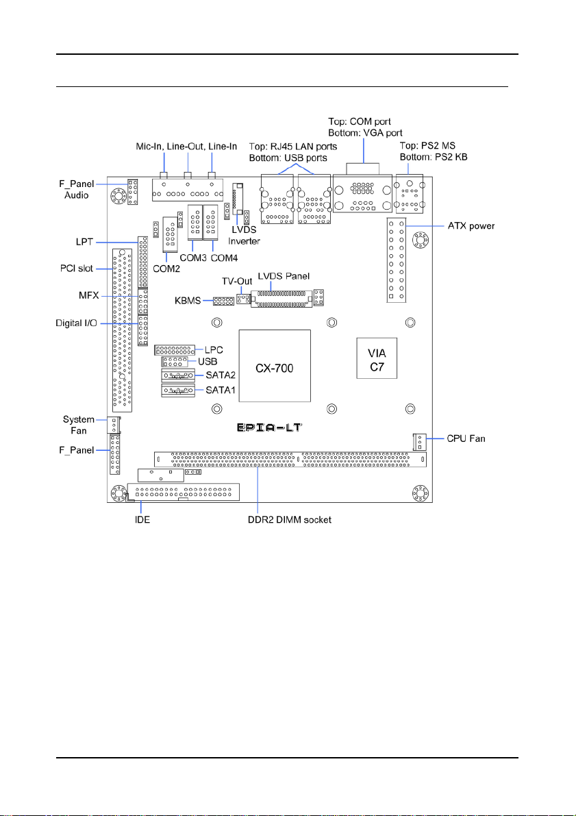
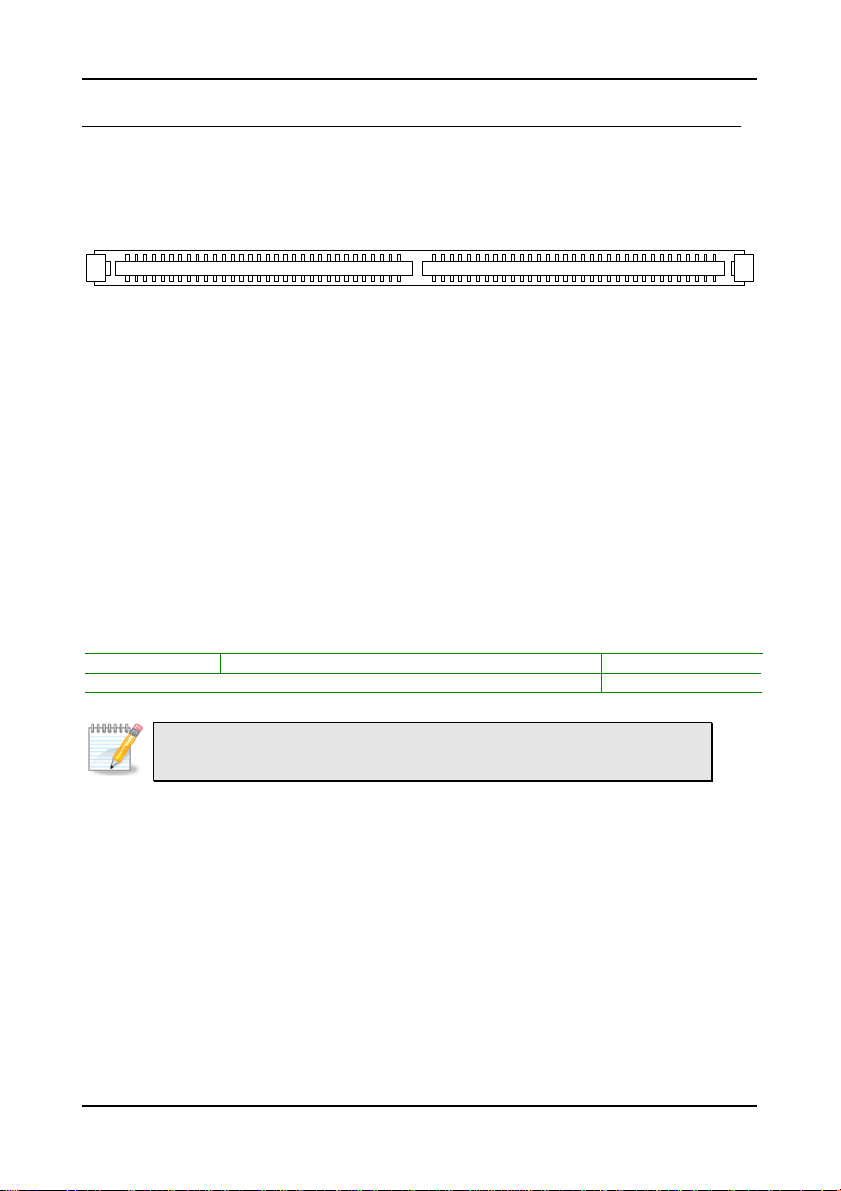
AINBOARD LAYOUT
4
Page 13
B
ACK PANEL LAYOUT
Specifications
5
Page 14

Chapter 1
This page is intentionally left blank.
6
Page 15

HAPTER
C
2
Installation
This chapter provides you with information about hardware
installation procedures. It is recommended to use a grounded wrist
strap before handling computer components. Electrostatic discharge
(ESD) can damage some components.
7
Page 16
Chapter 3
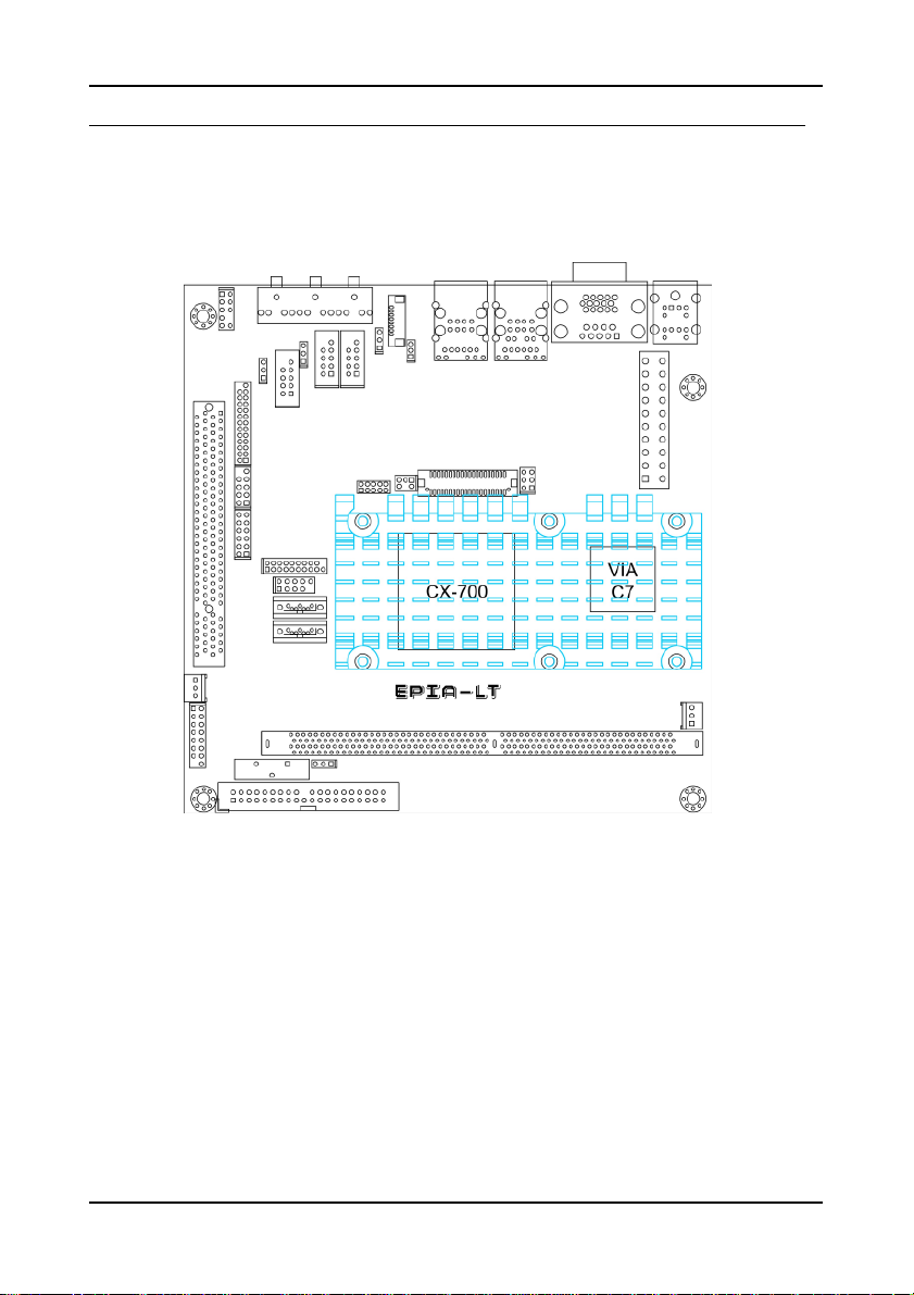
CPU
The VIA EPIA-LT Mini-ITX mainboard includes an embedded VIA C7 V4 Bus
Processor. The VIA C7 V4 Bus Processor requires only a heatsink to provide
sufficient cooling.
8
Page 17
BIOS Setup
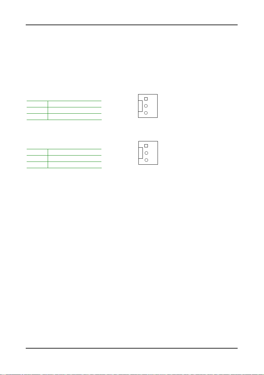
CPUFAN
CPU Fan and System Fan: CPUFAN and SYSFAN
The CPUFAN (CPU fan) and SYSFAN (system fan) run on +12V and maintain
system cooling. When connecting the wire to the connectors, always be
aware that the red wire is the Positive and should be connected to the +12V.
The black wire is Ground and should always be connected to GND.
CPUFAN
Pin Signal
1 NC
2 +12V
3 GND
SYSFAN
Pin Signal
1 NC
2 +12V
3 GND
1
SYSFAN
1
9
Page 18
Chapter 3
M
EMORY MODULE INSTALLATION
The VIA EPIA-LT Mini-ITX mainboard provides one 240-pin DIMM slot for
DDR2 533 SDRAM memory modules and supports the memory size up to 1GB.
DIMM
DDR SDRAM Module Installation Procedures
• Locate the DIMM slot in the motherboard.
• Unlock a DIMM slot by pressing the retaining clips outward.
• Align a DIMM on the socket such that the notch on the DIMM
matches the break on the slot.
• Firmly insert the DIMM into the slot until the retaining clips snap
back in place and the DIMM is properly seated.
Available DDR SDRAM Configurations
Refer to the table below for available DDR SDRAM configurations on the
mainboard.
Slot Module Size Total
DIMM 64MB, 128MB, 256MB, 512MB, 1GB 64MB-1GB
Maximum supported system memory 64MB-1GB
Note:
Only supports 1GB SDRAM with 64M x 8bits x16 configuration.
10
Page 19
BIOS Setup
C
ONNECTING THE POWER SUPPLY
The VIA EPIA-LT Mini-ITX mainboard supports a conventional ATX power
supply for the power system. Before inserting the power supply connector,
always make sure that all components are installed correctly to ensure that
no damage will be caused.
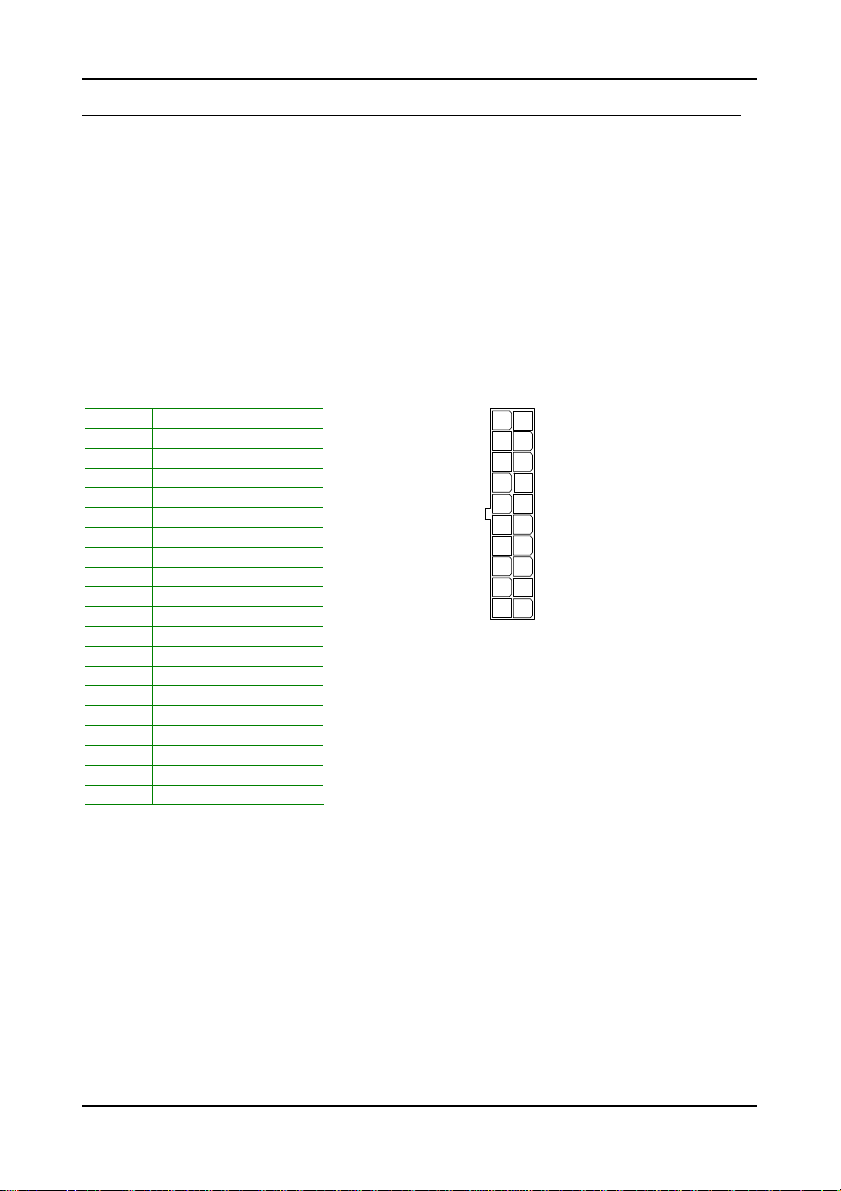
ATX 20-Pin Power Connector
To connect the ATX power supply, make sure the power plug is inserted in
the proper orientation and the pins are aligned. Then push down the plug
firmly into the connector.
Pin Signal
1 +3.3V
2 +3.3V
3 GND
4 +5V
5 GND
6 +5V
7 GND
8 Power Good
9 +5V Standby
10 +12V
11 +3.3V
12 -12V
13 GND
14 Power Supply On
15 GND
16 GND
17 GND
18 -5V
19 +5V
20 +5V
ATXPWR
11
20
1
10
11
Page 20
Chapter 3
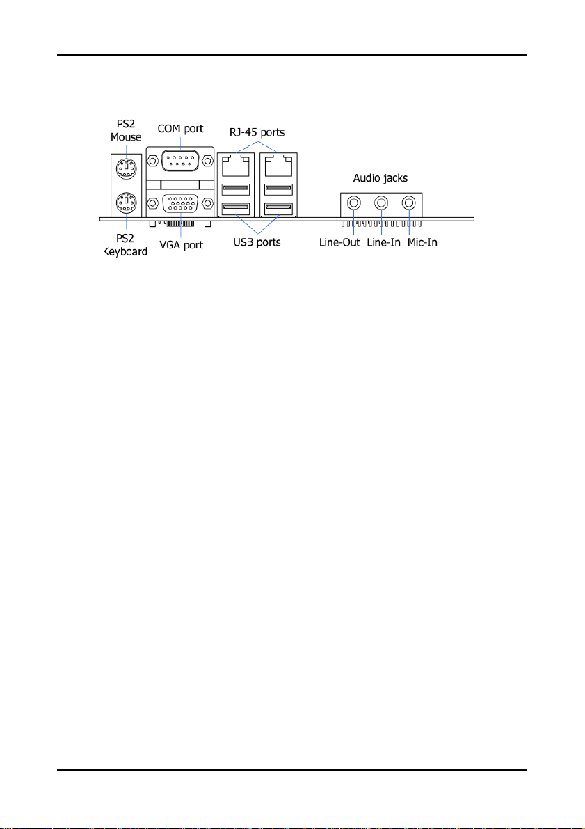
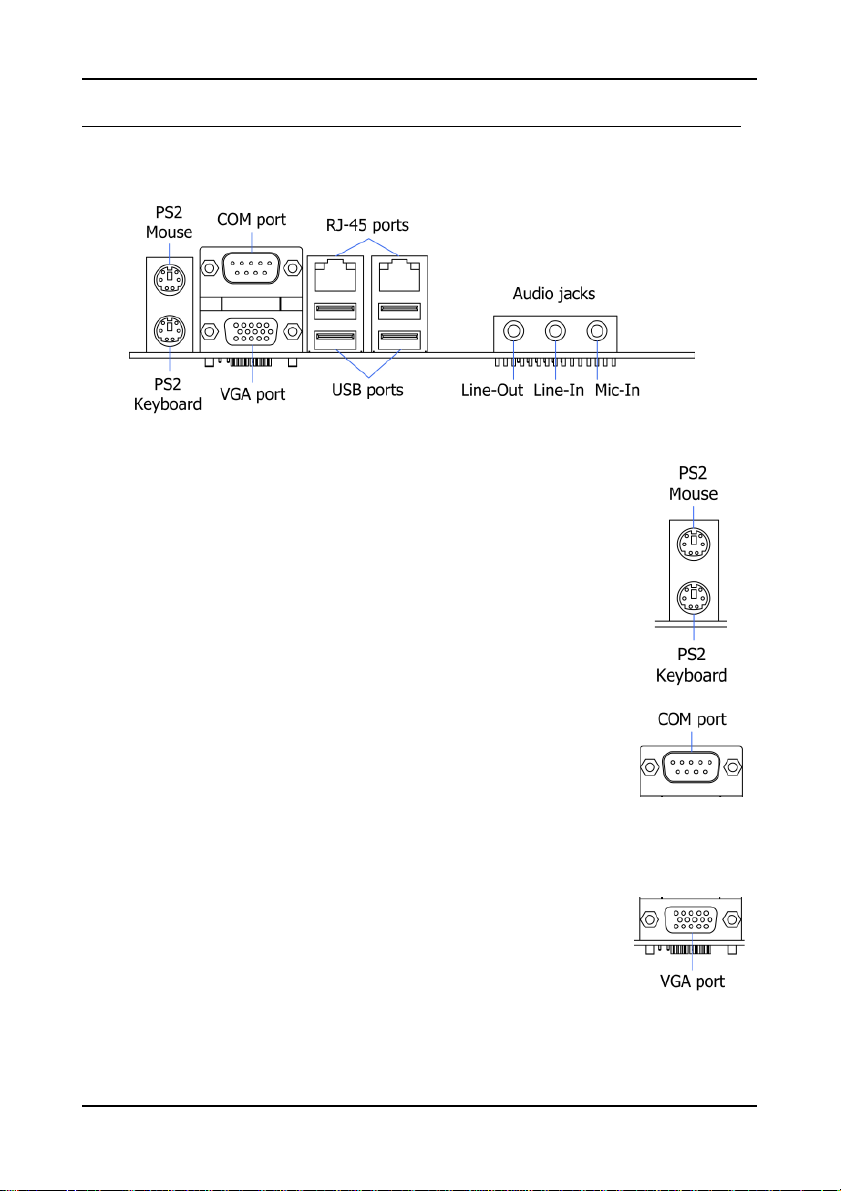
B
ACK PANEL PORTS
The back panel has the following ports:
Mouse and Keyboard
The connector above is for a PS/2 mouse, and the one below is
for a PS/2 keyboard.
Serial port: COM
The 9-pin COM port is for pointing devices or other serial
devices.
VGA Port
The 15-pin female VGA connector can be used to connect to
any analog VGA monitor.
12
Page 21
BIOS Setup
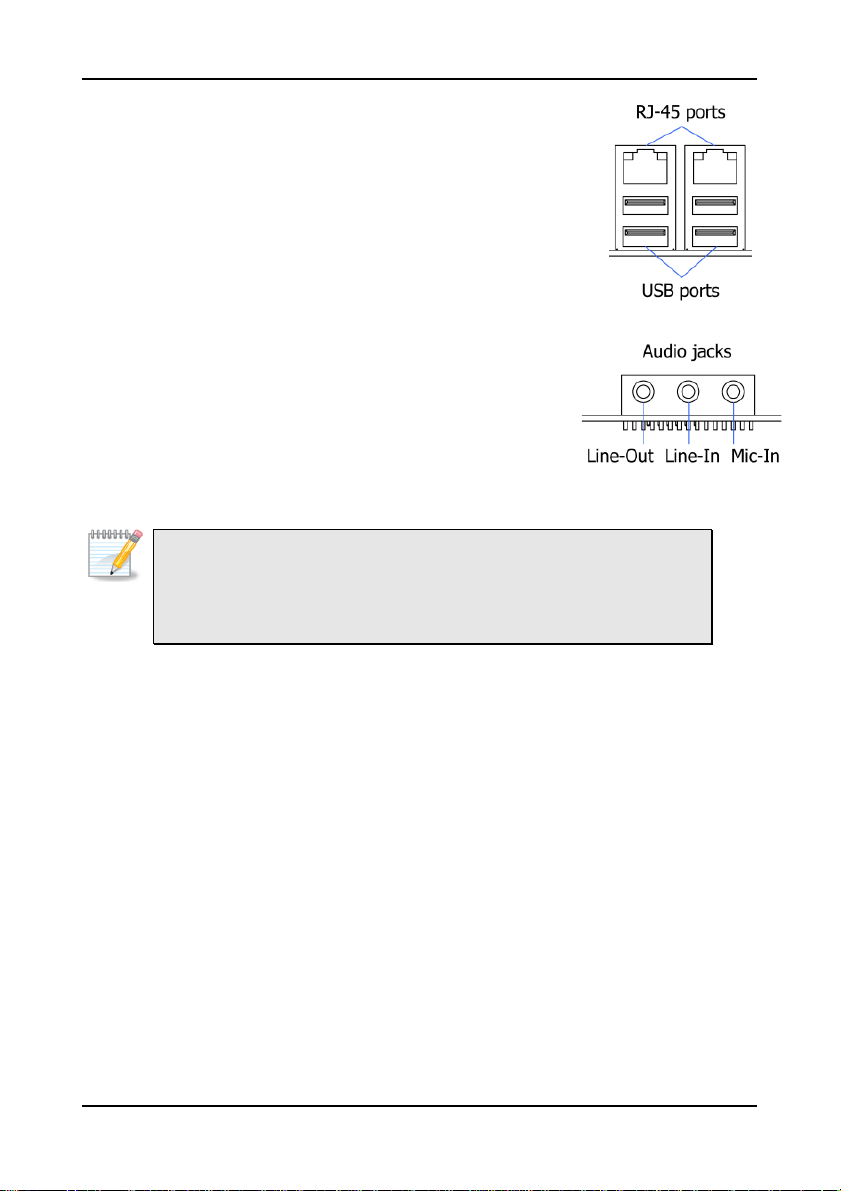
RJ45 10/100 LAN and USB Connectors
The mainboard provides a standard RJ-45 and USB 2.0
ports. These ports allow connection to a Local Area
Network (LAN) through a network hub and USB 2.0
devices.
Audio Port
The Line-Out jack is for connecting to external speakers
or headphones. The Line-In jack is for connecting to
an external audio device such as a CD player, tape
player, etc. The Mic jack is for connecting to a
microphone.
Note:
The audio ports can be switched to Smart 5.1 6-channel audio output.
You can enable the function by clicking the “Vinyl Audio” icon on your
desktop after installing the audio driver.
After completing the previous installation, connect the speakers to the 3-jack
connectors on the back panel.
13
Page 22

Chapter 3
IDE1
SATA1-2
USB
2
C
ONNECTORS
Hard Disk Connectors: IDE1
The mainboard has a 32-bit Enhanced IDE and Ultra DMA 133/100/66
controller that provides PIO mode 0~4, Bus Master, and Ultra DMA
133/100/66 functions. You can connect up to four hard disk drives, CD-ROM
and other devices.
1
Serial ATA Connectors: SATA1 and SATA2
These next generation connectors support the thin Serial ATA
cables for primary internal storage devices. The current Serial
ATA interface allows up to 150MB/s data transfer rate, faster
than the standard parallel ATA with 133 MB/s (Ultra DMA).
USB Pin Connector: USB
The mainboard provides one USB pin header, allowing up to 2 additional
USB2.0 ports up to maximum throughput of 480 Mbps. Connect each 2-port
USB cable into this pin header. This port can be used to connect high-speed
USB interface peripherals such as USB HDD, digital cameras, MP3 players,
printers, modem and the like.
Pin Signal Pin Signal
1 VUSB0 2 VUSB0
3 USBD_T0- 4 USBD_T15 USBD_T0+ 6 USBD_T1+
7 GND 8 GND
9 Key 10 GND
1
9
10
14
Page 23

BIOS Setup
F_PANEL
Case Connector: F_PANEL
The F_PANEL pin header allows you to connect the power switch, reset switch,
power LED, sleep LED, HDD LED and the case speaker.
Pin Signal Pin Signal
1 +PWR_LED 2 +HD_LED
3 +PWR_LED 4 -HD_LED
5 -PWR_LED 6 PW_BN
7 SPEAK+ 8 GND
9 NC 10 RST_SW
11 NC 12 GND
13 SPEAK- 14 +SLEEP_LED
15 Key 16 -SLEEP_LED
1 2
15 16
Power Switch (PW_BN)
Connect to a 2-pin power button switch. Pressing this button will turn the
system power on or off.
Reset Switch (RST_SW)
The reset switch is used to reboot the system rather than turning the power
ON/OFF. Avoid rebooting the system, if the HDD is still working. Connect
the reset switch from the system case to this pin.
Power LED (-PLED)
The LED will light when the system is on. If the system is in S1 (POS - Power
On Suspend) or S3 (STR - Suspend To RAM) state, the LED will blink.
HDD LED (HD_LED)
HDD LED shows the activity of a hard disk drive. Avoid turning the power off
when the HDD LED still has a lit. Connect the HDD LED from the system case
to this pin.
Speaker
The speaker from the system case is connected to this pin.
15
Page 24

Chapter 3
9
Front Panel Audio Connector: F_AUDIO
This is an interface for the VIA front panel audio cable that allow convenient
connection and control of audio devices. By default, the pins labeled
LINE_OUT_R/NEXT_R and the pins LINE_OUT_L/NEXT_L are shorted with
jumper caps. Remove the caps only when you are connecting the front panel
audio cable.
F_AUDIO
Pin Signal Pin Signal
1 MICIN_L 2 AUD_GND
3 MICIN_R 4 -PRESENSE
5 HPOUT_R 6 AUD_RET_R
7 FRONT_IO_SENSE 8 Key
9 HPOUT_L 10 AUD_RET_L
1 2
10
Note:
If you don’t want to connect to the front audio header, pins 5 & 6, 9 & 10
have to be jumpered in order to have signal output directed to the rear
audio ports. Otherwise, the Line-Out connector on the back panel will not
function.
Consumer Infrared Module / PS2 Header: CIR / KBMS
The mainboard provides a CIR pin header. It is also convertible to a KBMS
pin header which is to attach a PS/2 keyboard and mouse.
Pin Signal Pin Signal
1 +5VDUAL 2 GND
3 KB_CLK 4 KB_DATA
5 EXT_KBCLK 6 EXT_KBDATA
7 MS_CLK 8 MS_DATA
9 EXT_MSCLK 10 EXT_MSDATA
Note:
When the pin header is not in use, please short pin 3&5, pin 4&6, pin
7&9, and pin 8&10.
CIR/KBMS
1 2
109
16
Page 25

BIOS Setup
LPC
Serial Port Connectors: COM2, COM3, and COM4
COM2/3/4 pin headers can be used to attach additional ports for serial mouse
or other serial devices.
COM2/3/4
Pin Signal Pin Signal
1 DCD 2 RXD
3 TXD 4 DTR
5 GND 6 DSR
7 RTS 8 CTS
9 RI 10 Key
1 2
9 10
Digital I/O Connector: DIO
General purpose input and output for POS systems.
DIO
Pin Signal Pin Signal
1 5V_DIO 2 12V_DIO
3 GPO_21 4 GPI_44
5 GPO_22 6 GPI_45
7 GPO_32 8 GPI_46
9 GPO_33 10 GPI_47
11 GND 12 GND
1 2
11 12
LPC Connector: LPC
This pin connector is for LPC devices.
Pin Signal Pin Signal
1 LAD1 2 LPC_33_CLK
3 -PCIRSTX 4 GND
5 LAD0 6 SIO_48_OSC
7 LAD2 8 -LFRAME
9 SERIRQ 10 LAD3
11 -LDRQ1 12 -EXTSMI
13 +5V 14 +3.3V
15 +5V 16 +3.3V
17 GND 18 GND
19 GND 20 Key
17
1 2
2019
Page 26

Chapter 3
LPT
LPT Connector: LPT
The mainboard provides a 26-pin connector to be able to connect a 25-pin
female external connector for LPT (parallel port). A parallel port is a standard
printer port that supports Enhanced Parallel Port (EPP) and Extended
Capabilities Parallel Port (ECP) modes.
Pin Signal Pin Signal
1 -LP_STB 2 -LP_AFD
3 LP_D0 4 -LP_ERR
5 LP_D1 6 -LP_INIT
7 LP_D2 8 -LP_SLIN
9 LP_D3 10 GND
11 LP_D4 12 GND
13 LP_D5 14 GND
15 LP_D6 16 GND
17 LP_D7 18 GND
19 -LP_ACK 20 GND
21 LP_BUSY 22 GND
23 LP_PE 24 GND
25 LP_SLCT 26 Key
1 2
2625
18
Page 27

BIOS Setup
LVDS Panel Connector: PANEL
The LVDS Panel connector allow you to connect the panel’s LVDS cable
directly to support LVDS panel without any need of a daughter card.
Pin Signal Pin Signal
1 -LD2C4 2 PVDD
3 +LD2C4 4 PVDD
5 GND 6 GND
7 -LD2C5 8 GND
9 +LD2C5 10 -LD1C0
11 GND 12 +LD1C0
13 -LD2C6 14 GND
15 +LD2C6 16 -LD1C1
17 GND 18 +LD1C1
19 -LCLK2 20 GND
21 +LCLK2 22 -LD1C2
23 GND 24 +LD1C2
25 -LD2C7 26 GND
27 +LD2C7 28 -LCLK1
29 NC 30 +LCLK1
31 NC 32 GND
33 NC 34 -LD1C3
35 NC 36 +LD1C3
37 NC 38 GPIOA_CLK
39 NC 40 GPIOB_DATA
2
40
1
39
Inverter Connector: INVERTER
The mainboard provides an inverter for supplying power to the backlight of
the LCD panel.
Pin Signal
1 IVDD
2 IVDD
3 BLON
4 NC
5 BLON
6 BR_CNTR
7 GND
8 GND
19
Page 28

Chapter 3
MFX
MFX Pin connector
This pin connector is for MFX-01 add-on cards. This pin header also allows
you to connect SMBus (System Management Bus) devices (using pins 4, 6,
and 8). Such devices communicate with a SMBus host and/or other SMBus
devices using the SMBus interface.
Pin Signal Pin Signal
1 +5V 2 +5VSUS
3 PW_BN 4 SMB_CLK
5 NC 6 SMB_DAT
7 NC 8 GND
9 GND 10 Key
TV Connector: TV
This pin connector allows you to connect to a TV set.
Pin Signal Pin Signal
1 Y (Y, G) 2 GND
3 Pr (C, R) 4 Key
5 Pb (CVBS, B) 6 GND
1 2
9 10
TV
1 2
5
6
20
Page 29

BIOS Setup
132
J
UMPERS
The mainboard provides jumpers for setting some mainboard functions. This
section will explain how to change the settings of the mainboard functions
using the jumpers.
Clear CMOS: CLEAR_CMOS
The onboard CMOS RAM stores system configuration data and has an
onboard battery power supply. To reset the CMOS settings, set the jumper
on pins 2 and 3 while the system is off. Return the jumper to pins 1 and 2
afterwards. Setting the jumper while the system is on will damage the
mainboard.
Clear
Setting 1 2 3
Clear CMOS setting OFF ON ON
Keep CMOS setting ON ON OFF
1 32
Keep
Caution:
Except when clearing the RTC RAM, never remove the cap on
CLEAR_CMOS jumper default position. Removing the cap will cause
system boot failure. Avoid clearing the CMOS while the system is on; it
will damage the mainboard.
1 32
Voltage Selector for COM Connectors: J1/2/3
This VCC selector is to determine the input voltage of each COM connector.
Setting 1 2 3
+5V ON ON OFF
+12V OFF ON ON
+5V:
1 32
+12V:
21
Page 30

Chapter 3
+3.3V
+5V
+12V
132
Inverter Selector: IVDD_SEL
IVDD is the VCC selector jumper to determine the input voltage of the panel
inverter for panel’s back-light.
Setting 1 2 3
+5V ON ON OFF
+12V OFF ON ON
+5V:
1 32
+12V:
4
1 2
3
5 6
4
Panel Power Selector: PVDD_SEL
PVDD is the VCC selector jumper to determine
the panel’s signal voltage.
Setting 1 2 3 4 5 6
+12V ON ON OFF OFF OFF OFF
+5V OFF OFF ON ON OFF OFF
+3.3V OFF OFF OFF OFF ON ON
1 2
3
5 6
1 2
3
5 6
4
22
Page 31

BIOS Setup
PCI
S
LOTS
Peripheral Component Interconnect: PCI
The PCI slot allows you to insert PCI expansion card. When adding or
removing expansion card, unplug first the power supply. Read the
documentation for the expansion card if any changes to the system are
necessary.
PCI Interrupt Request Routing
The IRQ (interrupt request line) are hardware lines over which devices can
send interrupt signals to the microprocessor. The “PCI & LAN” IRQ pins are
typically connected to the PCI bus INT A# ~ INT D# pins as follows:
Order 1 Order 2 Order 3 Order 4
PCI Slot 1 INT B# INT C# INT D# INT A#
23
Page 32

Chapter 3
This page is intentionally left blank.
24
Page 33

HAPTER
C
3
BIOS Setup
This chapter gives a detailed explanation of the BIOS setup functions.
25
Page 34

Chapter 3
E
NTERING SETUP
Power on the computer and press <Delete> during the beginning of the boot
sequence to enter the BIOS setup menu. If you missed the BIOS setup entry
point, you may restart the system and try again.
26
Page 35

BIOS Setup
C
ONTROL KEYS
Keys Description
Up Arrow Move to the previous item
Down Arrow Move to the next item
Left Arrow Move to the previous tab
Right Arrow Move to the next tab
Enter Select the item
Escape Jumps to the Exit menu or returns to the main menu from a
+ Increase the numeric value
- Decrease the numeric value
F1 General help, only for Status Page Setup Menu and Option
F7 Discard Changes
F9 Load Optimized defaults
F10 Save all the changes and exit
submenu
Page Setup Menu
27
Page 36

Chapter 3
G
ETTING HELP
The BIOS setup program provides a “General Help” screen. You can display
this screen from any menu/sub-menu by pressing <F1>. The help screen
displays the keys for using and navigating the BIOS setup. Press <Esc> to
exit the help screen.
28
Page 37

M
AIN MENU
AMIBIOS
BIOS version number and related information.
Processor
CPU information.
BIOS Setup
System Memory
Memory size.
System Time
Use the key “+” or “-” to configure system time. The time format is [Hour :
Minute : Second].
System Date
Use the key “+” or “-” to configure system Date. The date format is [Day,
Month, Date, Year].
29
Page 38

Chapter 3
A
DVANCED SETTINGS
CPU Configuration
IDE Configuration
Super I/O Configuration
Hardware Health Configuration
ACPI Configuration
APM Configuration
Remote Access Configuration
USB Configuration
30
Page 39

BIOS Setup
CPU C
ONFIGURATION
CMPXCHG8B instruction support
Settings: [Enabled, Disabled]
VIA Processor Power Management
Setting Description
Enabled This selection enables CPU speed to be adjustable according to
Disabled Disable the function and CPU will be working in high speed.
system loads in order to lower power consumption.
31
Page 40

Chapter 3
IDE C
ONFIGURATION
Parallel ATA IDE Controller
Settings: [Disabled, Primary, Secondary, Both]
Hard Disk Write Protect
Settings: [Enabled, Disabled]
IDE Detect Time Out (Sec)
Settings: [0, 5, 10, 15, 20, 25, 30, 35]
ATA(PI) 80Pin Cable Detection
Settings: [Host & Device, Host, Device]
32
Page 41

BIOS Setup
IDE D
RIVES
Type
Settings: [Not Installed, Auto, CD/DVD, ARMD]
LBA/Large Mode
Settings: [Disabled, Auto]
Block (Multi-Sector Transfer)
Settings: [Disabled, Auto]
PIO Mode
Settings: [Auto, 0, 1, 2, 3, 4]
DMA Mode
Settings: [Auto]
S.M.A.R.T.
Self Monitoring Analysis and Reporting Technology, a monitoring system for
hard disks.
Settings: [Auto, Enabled, Disabled]
32Bit Data Transfer
Settings: [Enabled, Disabled]
33
Page 42

Chapter 3
S
UPER
I/O C
ONFIGURATION
Serial Port1 Address
Settings: [Disabled, 3F8, 3E8, 2E8]
Serial Port1 IRQ
Settings: [3, 4, 10, 11]
Serial Port2 Address
Settings: [Disabled, 2F8, 3E8, 2E8]
Serial Port2 IRQ
Settings: [3, 4, 10, 11]
Serial Port2 Mode
Settings: [Normal, IrDA, ASK IR]
Serial Port3 Address
Settings: [Disabled, A80, A88, A90, A98, AA0, AA8]
Serial Port3 IRQ
Settings: [3, 4, 10, 11]
34
Page 43

Serial Port4 Address
Settings: [Disabled, A80, A88, A90, A98, AA0, AA8]
Serial Port4 IRQ
Settings: [3, 4, 10, 11]
Parallel Port Address
Settings: [Disabled, 378, 278, 3BC]
Parallel Port Mode
Settings: [Normal, SPP (Bi-Dir), EPP+SPP, ECP, ECP+EPP]
Parallel Port IRQ
Settings: [IRQ5, IRQ7]
WATCH-DOG
Settings: [Disabled, Enabled]
BIOS Setup
35
Page 44

Chapter 3
H
ARDWARE HEALTH CONFIGURATION
Hardware Health Configuration
This item is used to enable or disable hardware health monitoring device.
Settings: [Enabled, Disabled]
36
Page 45

BIOS Setup
ACPI S
ETTINGS
General ACPI Configuration
This menu contains ACPI (Advanced Configuration and Power Management
Interface) options.
Advanced ACPI Configuration
Chipset ACPI Configuration
37
Page 46

Chapter 3
G
ENERAL
ACPI C
ONFIGURATION
Suspend mode
Select the ACPI state used for system suspend.
Setting Description
S1(POS) S1/Power On Suspend (POS) is a low power state. In this state,
S3(STR) S3/Suspend To RAM (STR) is a power-down state. In this state,
Auto Depends on the OS to select the state.
no system context (CPU or chipset) is lost and hardware
maintains all system contexts.
power is supplied only to essential components such as main
memory and wakeup-capable devices. The system context is
saved to main memory, and context is restored from the
memory when a "wakeup" event occurs.
Repost Video on S3 Resume
To determine whether to invoke VGA BIOS post on S3/STR resume or not.
Settings: [No, Yes]
38
Page 47

A
DVANCED
ACPI C
ONFIGURATION
ACPI 2.0 Features
To enable RSDP pointers to 64-bit Fixed System Description Tables.
Settings: [No, Yes]
BIOS Setup
ACPI APIC support
To include ACPI APIC table pointer to RSDT pointer list.
Settings: [Enabled, Disabled]
AMI OEMB table
To include OEMB table pointer to R(X)SDT pointer lists.
Settings: [Enabled, Disabled]
Headless mode
To enable or disable headless operation mode through ACPI.
Settings: [Enabled, Disabled]
39
Page 48

Chapter 3
C
HIPSET
USB Device Wakeup Function
Settings: [Enabled, Disabled]
ACPI C
ONFIGURATION
40
Page 49

BIOS Setup
APM C
ONFIGURATION
Power Management / APM
Settings: [Disabled, Enabled]
Power Button Mode
Settings: [On/Off, Standby, Suspend]
Suspend Power Saving Type
Settings: [C3, S1]
Restore on AC / Power Loss
The field defines how the system will respond after an AC power loss during
system operation.
Setting Description
Power Off Keeps the system in an off state until the power button is
Power On Restarts the system when the power is back
Last state Save in last state
pressed.
Standby Time Out
Settings: [Disabled, 1/2/4/8/10/20/30/40 minutes]
41
Page 50

Chapter 3
Suspend Time Out
Settings: [Disabled, 1/2/4/8/10/20/30/40 minutes]
Hard Disk Time Out
Settings: [Disabled, 1/2/3/4/5/6/7/8 minutes]
Green PC Monitor Power State
Settings: [Standby, Suspend, Off]
Video Power Down Mode
Settings: [Disabled, Standby, Suspend]
Hard Disk Power Down Mode
Settings: [Disabled, Standby, Suspend]
Display Activity
Settings: [Ignore, Monitor]
Monitor IRQ3~15
Enables or disables the monitoring of the specified IRQ line.
Settings: [Ignore, Monitor]
Note:
IRQ (Interrupt Request) lines are system resources allocated to I/O
devices. When an I/O device needs to gain attention of the operating
system, it signals this by causing an IRQ to occur. After receiving the
signal, when the operating system is ready, the system will interrupt itself
and perform the service required by the IO device.
Resume on PCI
Settings: [Disabled, Enabled]
Resume on KBC
Settings: [Disabled, S3, S3/S4/S5]
Wake-up Key
Settings: [Any Key, Specific Key]
42
Page 51

BIOS Setup
Resume on PS/2 Mouse
Enables any mouse activity to restore the system from the power saving
mode to an active state.
Settings: [Disabled, S3, S3/S4/S5]
Resume on RTC Alarm
Sets a scheduled time and/or date to automatically power on the system.
Settings: [Disabled, Enabled]
43
Page 52

Chapter 3
R
EMOTE ACCESS CONFIGURATION
Remote Access
To select Remote Access type.
Settings: [Disabled, Enabled]
44
Page 53

BIOS Setup
USB C
ONFIGURATION
USB 1.1 Ports Configuration
To enable USB 1.1 host controllers.
Settings: [Disabled, USB 2 ports, USB 4 ports, USB 6 ports]
USB 2.0 Ports Enable
To enable USB 2.0 host controllers.
Settings: [Disabled, Enabled]
Legacy USB Support
To enable support for legacy USB.
Settings: [Disabled, Enabled, Auto]
Port 64/60 Emulation
To enable I/O port 60h/64h emulation support.
Settings: [Disabled, Enabled]
45
Page 54

Chapter 3
USB 2.0 Controller Mode
To configure the USB 2.0 controller in HiSpeed (480Mbps) or FullSpeed
(12Mbps).
Settings: [HiSpeed, FullSpeed]
46
Page 55

A
DVANCED
PCIPNP S
Note:
This section covers some very technical items and it is strongly
recommended to leave the default settings as it is unless you are an
experienced user.
ETTINGS
BIOS Setup
Clear NVRAM
To clear NVRAM during system boot.
Settings: [No, Yes]
Plug & Play O/S
Settings: [No, Yes]
PCI Latency Timer
Value in units of PCI clocks for PCI device latency timer register.
Settings: [32, 64, 96, 128, 160, 192, 224, 248]
Allocate IRQ to PCI VGA
Settings: [No, Yes]
47
Page 56

Chapter 3
Palette Snooping
Settings: [Disabled, Enabled]
PCI IDE BusMaster
Settings: [Disabled, Enabled]
IRQ3~15
Settings: [Available, Reserved]
DMA Channel 0~7
Settings: [Available, Reserved]
Reserved Memory Size
To decide the size of memory block to reserve for legacy ISA devices.
Settings: [Disabled, 16k, 32k, 64k]
48
Page 57

B
OOT SETTINGS
Boot Settings Configuration
Configuration settings during system boot.
Boot Devices Priority
Specifies the boot device priority sequence.
BIOS Setup
49
Page 58

Chapter 3
B
OOT SETTINGS CONFIGURATION
Quick Boot
Settings: [Disabled, Enabled]
Quiet Boot
Settings: [Disabled, Enabled]
AddOn ROM Display Mode
Settings: [Force BIOS, Keep Current]
Bootup Num-Lock
To select power-on state for Num-Lock.
Settings: [Off, On]
PS/2 Mouse Support
Settings: [Disabled, Enabled, Auto]
50
Page 59

BIOS Setup
B
OOT DEVICE PRIORITY
1st Boot Device
To specifies the boot sequence from the available devices. The available boot
devices are detected dynamically according to real situation and variable
options will be provided.
Settings: [Network:VIA BootAgent, Disabled]
2nd Boot Device
Settings: [Network:VIA BootAgent, Disabled]
51
Page 60

Chapter 3
S
ECURITY SETTINGS
Change Supervisor Password
This option is for setting a password for entering BIOS Setup. When a
password has been set, a password prompt will be displayed whenever BIOS
Setup is run. This prevents an unauthorized person from changing any part
of your system configuration.
When a supervisor password is used, the BIOS Setup program can be
accessed and the BIOS settings can be changed.
Change User Password
When a user password is used, the BIOS Setup program can be accessed but
the BIOS settings cannot be changed.
Boot Sector Virus Protection
Settings: [Disabled, Enabled]
52
Page 61

A
DVANCED CHIPSET SETTINGS
Caution:
The Advanced Chipset Settings menu is used for optimizing the chipset
functions. Do not change these settings unless you are familiar with the
chipset.
BIOS Setup
North Bridge VIA CX700 Configuration
South Bridge VIA CX700 Configuration
53
Page 62

Chapter 3
N
ORTHBRIDGE
VIA CX700 C
Top Performance
Settings: [Disabled, Enabled]
Software Reset E2 issue
Settings: [Patch, Escape Patch]
ONFIGURATION
54
Page 63

ONC
HIP
VGA C
ONFIGURATION
VGA Frame Buffer Size
Settings: [32MB, 64MB, 128MB]
CPU Direct Access Frame Buffer
Settings: [Disabled, Enabled]
BIOS Setup
Select Display Device
Settings: [CRT, LCD, TV, HDTV, CRT+LCD, LCD+TV]
Panel Type
Settings: [02]
Outport Port
Settings: [DI0, DI1]
Dithering
Settings: [Disabled, Enabled]
55
Page 64

Chapter 3
TV H/W Layout
Settings: [Default, Composite+S-Video, S-Video+S-Video, Comp.+R/G/B,
Comp.+Y/Cb/Cr, Comp.+SDTV-R/G/B, Comp.+SDTV-Y/Pb/Pr, Composite, S-
Video]
TV Type
Settings: [NTSC, PAL/PAL B/PAL G/PAL H, PAL M, PAL N, PAL Nc, PAL I, PAL
D, NTSC Japan]
TV Output Connector
Settings: [CVBS (Composite), S-Video 0 (Y/C), R/G/B, Cr/Y/Cb, SDTV-R/G/B,
SDTV-Pr/Y/Pb, S-Video 1 (Y/C)]
HDTV Type
Settings: [SDTV 525I/480I NTSC, SDTV 625I/576I PAL, HDTV 480P/525P
NTSC, HDTV 576P/625P/ PAL, HDTV 720P, HDTV 1080I, HDTV 1080P]
HDTV Connector
Settings: [R/G/B, Pr/Y/Pb]
56
Page 65

S
OUTHBRIDGE
VIA CX700 C
Serial ATA IDE Controller
Settings: [IDE, RAID]
MC’97 Modem
Settings: [Disabled, Auto]
ONFIGURATION
BIOS Setup
High Definition Audio
Settings: [Disabled, Auto]
57
Page 66

Chapter 3
E
XIT OPTIONS
Save Changes and Exit
Exit system setup after saving the changes, or press “F10”.
Discard Changes and Exit
Exit system setup without saving any changes, or press “Esc”.
Discard Changes
Discard changes which have been done so far to any of the setup questions,
or press “F7”.
Load Optimal Defaults
Load optimal default values for all the setup items, or press “F9”. The default
optimized values are set by the mainboard manufacturer to provide a stable
system with optimized performance.
Load Failsafe Defaults
Load fail-safe default values for all the setup items, or press “F8”. The values
are set by the mainboard manufacturer to provide basic system performance.
This page is intentionally left blank.
58
Page 67

HAPTER
C
4
Driver Installation
This chapter gives you brief descriptions of each mainboard driver and
application. You must install the VIA chipset drivers first before
installing other drivers such as audio or VGA drivers. The applications
will only function correctly if the necessary drivers are already
installed.
59
Page 68

Chapter 4
D
RIVER UTILITIES
Getting Started
The Driver Utilities CD contains the driver utilities and software for enhancing
the performance of the mainboard.
Note:
The driver utilities and software are updated from time to time. The latest
updated versions are available at http://www.viaembedded.com/
60
Page 69

Driver Installation
Running the Driver Utilities CD
To start using the CD, insert the CD into the CD-ROM or DVD-ROM drive.
The CD should run automatically after closing the CD-ROM or DVD-ROM drive.
The driver utilities and software menu screen should then appear on the
screen. If the CD does not run automatically, click on the “Start” button and
select “Run…” Then type: "D:\Setup.exe".
Note:
D: might not be the drive letter of the CD-ROM/DVD-ROM in your system.
61
Page 70

Chapter 4
CD C
ONTENT
VIA 4in1 Drivers: Contains VIA ATAPI Vendor Support
Driver (enables the performance enhancing bus mastering
functions on ATA-capable Hard Disk Drives and ensures IDE
device compatibility), AGP VxD Driver (provides service routines
to your VGA driver and interface directly to hardware, providing
fast graphical access), IRQ Routing Miniport Driver (sets the
system's PCI IRQ routing sequence) and VIA INF Driver
(enables the VIA Power Management function).
VIA Graphics Driver: Enhances the onboard VIA graphic
chip.
VIA Audio Driver: Enhances the onboard VIA audio chip.
VIA USB 2.0 Driver: Enhances VIA USB 2.0 ports.
VIA LAN Driver: Enhances the onboard VIA 10/100M LAN
chip.
VIA RAID Driver: Support for SATA RAID devices.
Note:
EPIA-LT does not support video outputs of HDTV (YPbPr) and LCD.
Please DO NOT enable these functions in this system.
62
 Loading...