

Page 1
EMIO
EMIO----3450
EMIOEMIO
Quick
Quick Guide
QuickQuick
Key Features:
Key Features:
Key Features:Key Features:
• Compatible with Em-ITX form factor
• Optional support for WiFi, GPS,
Bluetooth, and HSPA/WCDMA/
EDGE/GPRS using miniPCIe module.
• Support one SIM slot
• Integrated 6W stereo audio power
amplifier
Guide
Guide Guide
3450
34503450
The EMIO-3450 Em-IO card is specially designed for Em-ITX form factor
mainboard. The combinations of both EMIO-3450 card and Em-ITX
mainboard is ideally suited for traffic, delivery, KIOSK, wireless, in-vehicle
system and fleet management applications.
The EMIO-3450 card can support one SIM card slot and four optional
wireless connectivity protocols for proper communication through
expansion modules. The four wireless protocols provide supports for
802.11b/g Wireless LAN, Bluetooth, GPS receiver and mobile network
such as HSPA/WCDMA/EDGE/GPRS. In addition, the EMIO-3450
offers HD Audio quality via a built-in 6W stereo audio power amplifier.
Specifications:
Specifications:
Specifications:Specifications:
• Bridge:
Bridge:
Bridge:Bridge:
PLX PEX8112 PCIe-to-PCI Bridge
• Mini PCIe Interface
Mini PCIe Interface
Mini PCIe InterfaceMini PCIe Interface
•
2 x Mini-PCIe slots
• SIM slot
SIM slot
SIM slotSIM slot
•
1 x SIM slot
• USB
USB
USBUSB
•
2 x USB 2.0 ports connector
• UART
UART
UARTUART
•
1 x D-sub 9-pin UART port
• Digital I/O
Digital I/O
Digital I/ODigital I/O
•
1 x D-sup 9 pin DIO port
• Digital I/O 5V Output:
Digital I/O 5V Output:
Digital I/O 5V Output:Digital I/O 5V Output:
•
1 x 2-Pole Phoenix connector (DC output for external GPIO device)
• Audio:
Audio:
Audio:Audio:
Onboard TI TPA1517, 6W stereo audio power
amplifier
•
3 x 3.5mm TRS jacks: Line-in, Speak-out, Mic-in
• WLAN (option):
WLAN (option):
WLAN (option): WLAN (option):
Reserved socket for EMIO-1530 WLAN module.
•
Supports IEEE802.11b/g
• Bluetooth (option):
Bluetooth (option):
Bluetooth (option):Bluetooth (option):
Reserved socket for EMIO-1531 Bluetooth module.
•
Bluetooth core specification version 2.1 compliant
+EDR supported module
• GPS (option):
GPS (option):
GPS (option):GPS (option):
Reserved socket for EMIO-1532 GPS receiver
module
•
SirFStarII base of 20-channel GPS receiver
•
Support external antenna
• 3G Mobile Broadband (option):
3G Mobile Broadband (option):
3G Mobile Broadband (option):3G Mobile Broadband (option):
Reserved MiniPCIe slots for mobile broadband
modules that supports HSPA/WCDMA/EDGE/GPRS.
•
EMIO-1534, Ericsson Mobile Broadband Module
F3307, data rate up to 7.2Mbps downlink and
2Mbps uplink.
•
EMIO-1538, Motorola Mobile Broadband Module
HTM1000, data rate up to 10.1Mbps downlink and
5.56Mbps uplink.
• Dimensions:
Dimensions:
Dimensions:Dimensions:
•
170 mm (W) x 120 mm (L)
• Operating Temperature:
Operating Temperature:
Operating Temperature:Operating Temperature:
•
-20°C ~ 70°C
•
With EMIO-1532 module: -20°C ~ 60°C;
•
With EMIO-1530 module: -20°C ~ 60°C
• Humidity:
Humidity:
Humidity:Humidity:
•
0% ~ 90% relative humidity, non-condensing
Packing List:
Packing List:
Packing List:Packing List:
EMIO
EMIO----3450
3450----00A1
EMIOEMIO
•
1 x EMIO-3450 Em-IO card
•
1 x Board-to-board audio cable (P/N: 99G33-190376)
•
1 x Board-to-board 2 port USB cable for USB connector
(P/N: 99G33-191036)
•
1 x Board-to-board 1 port USB cable for USB interface WLAN
connector (P/N: 99G33-191026)
•
1 x Hex spacer kit (P/N: 99G44-020192)
— 6 x M3*5.5*19mm
•
1 x Quick guide (P/N: 99G51-013064-10)
EMIO
EMIO----3450
EMIOEMIO
All of the above plus:
•
1 x EMIO-1531 Bluetooth module kit
•
1 x EMIO-1532 GPS module kit
•
1 x EMIO-1530 WLAN module kit (US version)
•
1 x Software driver and utility CD (P/N: 99G64-021358-100)
EMIO
EMIO----3450
EMIOEMIO
Same with EMIO-3450-01A1 except the WLAN module kit is the EU
version.
00A1
34503450
00A100A1
3450----01A1
01A1
34503450
01A101A1
3450----02A1
02A1
34503450
02A102A1
Note:
Note:
Note:Note:
Please ensure that all items in the packing list are present
before using this product. If any of the items are missing
or damaged, contact your distributor or sales
representative immediately.
P/N: 99G51-013064-10
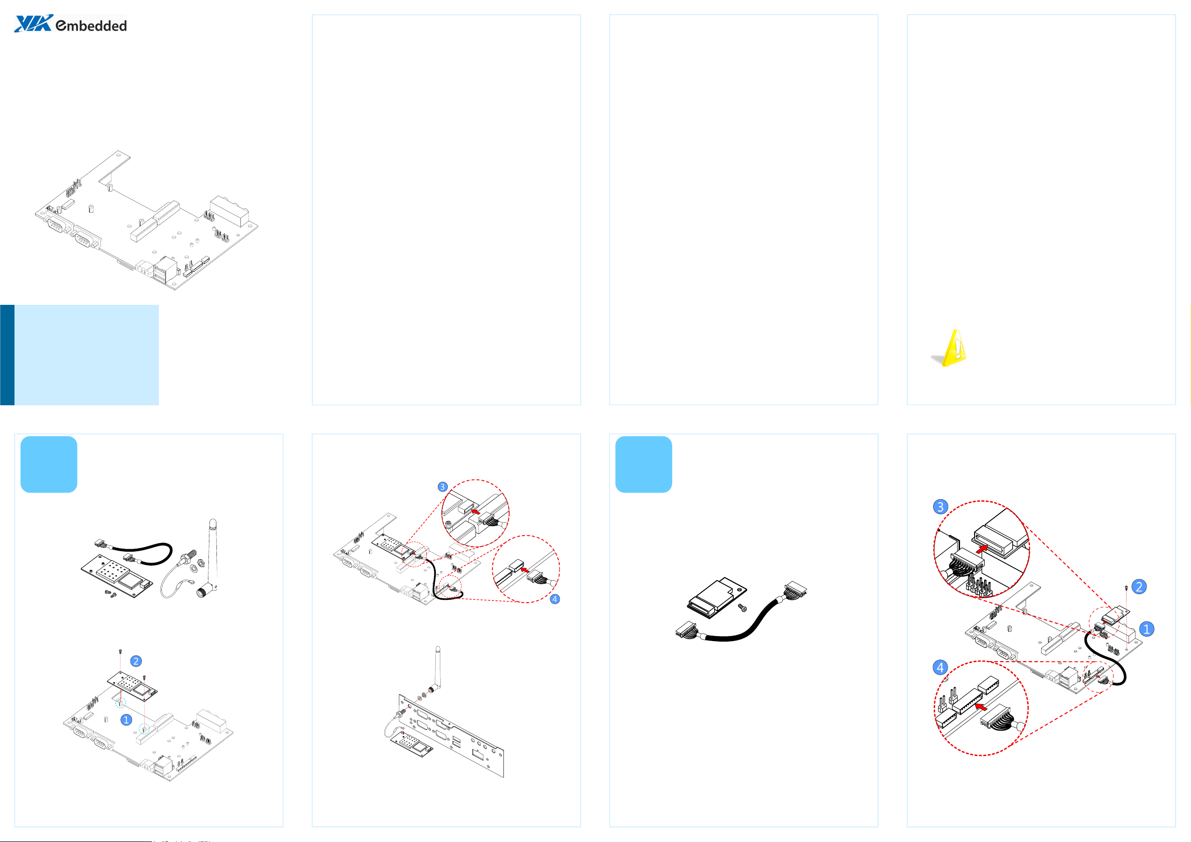
Installing the WLAN
Installing the WLAN
Installing the WLAN Installing the WLAN
module
module
1
The WLAN kit should include the WLAN module, two screws, one
board-to-board cable, one mini coaxial cable, one washer, one nut,
and one external antenna.
Step 1
Step 1
Step 1Step 1
Locate the mounting holes for the WLAN module. The mounting
holes have two standoffs pre-mounted. Then align the two
mounting holes on the WLAN module with the mounting holes
on the standoffs.
modulemodule
Step 3
Step 3
Step 3Step 3
Insert the one end of the WLAN signal cable into the connector on
the WLAN module. Be sure to have the metal contacts facing
down before inserting.
Step 4
Step 4
Step 4Step 4
Insert the other end of the WLAN signal cable into the connector
labeled JWLAN1 on the upper board. Be sure to have the metal
contacts facing down before inserting.
Installing the Bluetooth
Installing the Bluetooth
Installing the Bluetooth Installing the Bluetooth
module
module
2
The Bluetooth kit should include the Bluetooth module, one screw,
and one board-to-board cable.
The optional Bluetooth module includes a printed antenna and
uses the QCM-QBT400UB Bluetooth controller. The Bluetooth
module is classified as a Class 2 device with an effective range of 10
meters. It supports multi-point operation and a full 7-slave piconet.
Step 1
Step 1
Step 1Step 1
Locate the mounting hole for the Bluetooth module. The
mounting hole (labeled U31) is located next to the edge of the
upper board near the audio jacks.
modulemodule
Step 3
Step 3
Step 3Step 3
Insert one end of the Bluetooth signal cable into the connector on
the Bluetooth module. Be sure to have the metal contacts facing
down before inserting.
Step 2
Step 2
Step 2Step 2
Secure the WLAN module in place with the two screws provided
with the WLAN kit.
Step 5
Step 5
Step 5Step 5
Secure the WLAN antenna jack to the chassis with the toothed
washer and nut, then attach the antenna Connect the WLAN
antenna cable to the micro RF connector labeled MAIN on the
WLAN module.
Step 2
Step 2
Step 2Step 2
Align the mounting holes and secure the Bluetooth module to the
EMIO-3450.
Step 4
Step 4
Step 4Step 4
Insert the other end of the Bluetooth signal cable into the
connector labeled JBT1 on the upper board. Be sure to have the
metal contacts facing down before inserting.
Page 2
Pin
PinPin
Pin
Signal
SignalSignal
Signal Pin
PinPin
Pin
Signal
SignalSignal
Signal
Pin
PinPin
Pin
Signal
SignalSignal
Signal
Pin
PinPin
Pin
Signal
SignalSignal
Signal
3
Pin
PinPin
Pin
Signal
SignalSignal
Signal Pin
PinPin
Pin
Signal
SignalSignal
Signal
Pin
PinPin
Pin
Signal
SignalSignal
Signal Pin
PinPin
Pin
Signal
SignalSignal
Signal
Pin
PinPin
Pin
Signal
SignalSignal
Signal
Pin
PinPin
Pin
Signal
SignalSignal
Signal Pin
PinPin
Pin
Signal
SignalSignal
Signal
Pin
PinPin
Pin
Signal
SignalSignal
Signal Pin
PinPin
Pin
Signal
SignalSignal
Signal
Pin
PinPin
Pin
Signal
SignalSignal
Signal
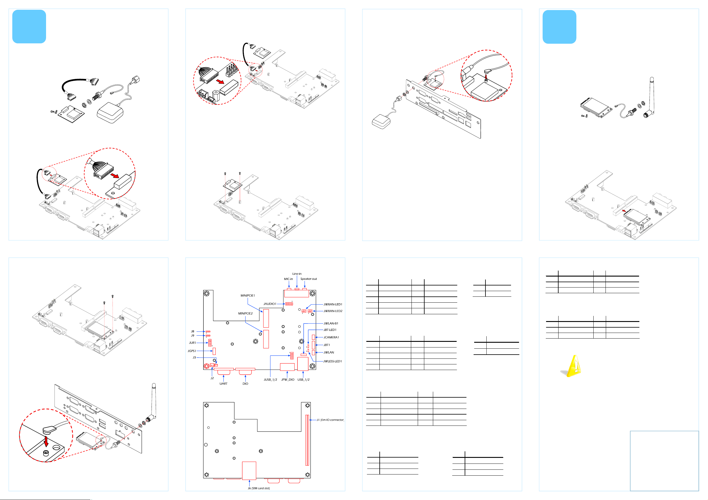
Installing the GPS
Installing the GPS
Installing the GPS Installing the GPS
module
module
modulemodule
Step 2
Step 2
Step 2Step 2
Insert the other end of the GPS signal cable into the connector
labeled JGPS1 on the upper board. Be sure to have the metal
contacts facing down before inserting.
Step 5
Step 5
Step 5Step 5
Insert the antenna cable (provided with the GPS kit) into the GPS
antenna hole. Secure the GPS antenna jack to the chassis with the
toothed washer and nut. Then attach the antenna provide with
4
Installing the Mobile
Installing the Mobile
Installing the MobileInstalling the Mobile
Broadband module
Broadband module
Broadband moduleBroadband module
The GPS kit should include the GPS module, two screws, one
board-to-board cable, one mini coaxial cable, one washer, one nut,
and one external antenna.
The optional GPS module includes a Leadtek LR9102 20-channel
GPS receiver.
Step 1
Step 1
Step 1Step 1
Insert one end of the GPS signal cable into the connector on the
GPS module. Be sure to have the metal contacts facing down
before inserting.
Step 3
Step 3
Step 3Step 3
Locate the mounting holes for the GPS module. The mounting
holes have two standoffs pre-mounted on the upper board next to
the mounting location of the WLAN module.
Step 4
Step 4
Step 4Step 4
Align the two mounting holes on the GPS module with the
mounting holes on the standoffs. Then secure the GPS module
with two screws.
Step 6
Step 6
Step 6Step 6
Connect the other end of the GPS antenna cable to the micro-RF
connector on the GPS module.
The Mobile Broadband kit should include the broadband module,
one screw, one mini coaxial cable, one washer, one nut, and one
external antenna. The broadband module options of EMIO-1534
(Ericsson Mobile Broadband Module F3307) or EMIO-1538
(Motorola Mobile Broadband Module HTM1000).
Step 1
Step 1
Step 1Step 1
Locate the Mini-PCIe slot (MINIPCIE2) near the center of the upper
board.
Step 2
Step 2
Step 2Step 2
Align the notch on the Mobile Broadband module with the notch
on the Mini-PCIe slot (MINIPCIE2) then insert the module
horizontally.
Step 3
Step 3
Step 3Step 3
Once the module has been fully inserted, secure the module with
two screws to the standoffs.
Step 4
Step 4
Step 4Step 4
Insert the antenna cable into the Mobile broadband antenna hole
from the inside. Secure the Mobile Broadband antenna jack to the
chassis with the toothed washer and nut.
Step 5
Step 5
Step 5Step 5
Attach the antenna provide with the Mobile Broadband kit to the
Mobile Broadband antenna jack.
Layout
Layout Pinouts
LayoutLayout
(Top view)
(Top view)
(Top view)(Top view)
(Bottom View)
(Bottom View)
(Bottom View)(Bottom View)
Pinouts
PinoutsPinouts
JAUDIO1
JAUDIO1
JAUDIO1JAUDIO1
1 LINE_OUT_R 2 LINE_OUT_L
3 LINE_IN_R 4 LINE_IN_L
5 MIC_R_R 6 MIC_R_L
7 KEY 8 NC
9 AGND 10 AGND
JUSB_1/2
JUSB_1/2
JUSB_1/2JUSB_1/2
1 VUSB4 2 VUSB4
3 USBD_T3- 4 USBD_T45 USBD_T3+ 6 USBD_T4+
7 GND 8 GND
9 Key 10 GND
JUR1
JUR1
JUR1JUR1
1 -DCD_2 2 SIO_RXD2-UR
3 SIO_TXD2-UR 4 -DTR_2
5 GND 6 -DSR_2
7 -RTS_2 8 -CTS_2
9 -RI_2 10 key
J9
J9
J9J9
1 SIO_RXD2-UR
2 RXD_2
3 SIO_RXD2-PMM
JBT
JBT----LED1
LED1
JBTJBT
LED1LED1
1 BT_LED
2 GND
JWLESS
JWLESS----LED1
JWLESSJWLESS
1 W_LESS_LED
2 GND
J8
J8
J8J8
1 SIO_TXD2-UR
2 TXD_2
3 SIO_TXD2-PMM
LED1
LED1LED1
JWXAN
JWXAN----LED1
JWXANJWXAN
1 WWAN_LED+ 2 WWAN_LED3 WLAN_LED+ 4 WLAN_LED5 WPAN_LED+ 6 WPAN_LED-
JWXAN
JWXAN----LED2
JWXANJWXAN
1 WWAN_LED+ 2 WWAN_LED3 WLAN_LED+ 4 WLAN_LED5 WPAN_LED+ 6 WPAN_LED-
For more information on this and
other VIA products, please visit
www.viaembedded.com.
For further support and service,
please visit www.via.com/tw/en/
products/mainboards/contact.jsp
LED1 (for MINIPCIE1 slot)
(for MINIPCIE1 slot)
LED1 LED1
(for MINIPCIE1 slot)(for MINIPCIE1 slot)
LED2 (for MINIPCIE2 slot)
(for MINIPCIE2 slot)
LED2 LED2
(for MINIPCIE2 slot)(for MINIPCIE2 slot)
Note:
Note:
Note:Note:
WWAN — Wireless Wide Area Network
WLAN — Wireless Local Area Network
WPAN—Wireless Personal Area Network
VIA Technologies, Inc.
1F, 531, Zhong-Zheng Road,
Xindian Dist., Taipei New City
231, Taiwan
Tel: 886-2-2218-5452
Fax: 886-2-2218-5453
Web: www.via.com.tw
Copyright © 2011 VIA Technologies, Inc. All rights reserved.
 Loading...