

Page 1

USER MANUAL
ARTiGO-A1250
Low Profile System with EPIA-P910
1.03-09142015-153500
Page 2

Copyright
Copyright © 2015 VIA Technologies Incorporated. All rights reserved.
No part of this document may be reproduced, transmitted, transcribed, stored in a retrieval system, or translated into any language,
in any form or by any means, electronic, mechanical, magnetic, optical, chemical, manual or otherwise without the prior written
permission of VIA Technologies, Incorporated.
Trademarks
All trademarks are the property of their respective holders.
Disclaimer
No license is granted, implied or otherwise, under any patent or patent rights of VIA Technologies. VIA Technologies makes no
warranties, implied or otherwise, in regard to this document and to the products described in this document. The information
provided in this document is believed to be accurate and reliable as of the publication date of this document. However, VIA
Technologies assumes no responsibility for the use or misuse of the information (including use or connection of extra
device/equipment/add-on card)
The information and product specifications within this document are subject to change at any time, without notice and without
obligation to notify any person of such change.
VIA Technologies, Inc. reserves the right the make changes to the products described in this manual at any time without prior
notice.
Regulatory Compliance
FCC
FCC----A Radio Frequency Interference Statement
A Radio Frequency Interference Statement
FCCFCC
A Radio Frequency Interference Statement A Radio Frequency Interference Statement
This equipment has been tested and found to comply with the limits for a class A digital device, pursuant to part 15 of the FCC
rules. These limits are designed to provide reasonable protection against harmful interference when the equipment is operated in a
commercial environment. This equipment generates, uses, and can radiate radio frequency energy and, if not installed and used in
accordance with the instruction manual, may cause harmful interference to radio communications. Operation of this equipment in a
residential area is likely to cause harmful interference, in which case the user will be required to correct the interference at his
personal expense.
Notice 1
Notice 1
Notice 1Notice 1
The changes or modifications not expressly approved by the party responsible for compliance could void the user's authority to
operate the equipment.
Notice 2
Notice 2
Notice 2Notice 2
Shielded interface cables and A.C. power cord, if any, must be used in order to comply with the emission limits.
Notice 3
Notice 3
Notice 3Notice 3
The product described in this document is designed for general use, VIA Technologies assumes no responsibility for the conflicts
or damages arising from incompatibility of the product. Check compatibility issue with your local sales representatives before
placing an order.
in this document and for any patent infringements that may arise from the use of this document.
Tested To Comply
With FCC Standards
FOR HOME OR OFFICE USE
Page 3
Battery Recycling and Disposal
Only use the appropriate battery specified for this product.
Do not re-use, recharge, or reheat an old battery.
Do not attempt to force open the battery.
Do not discard used batteries with regular trash.
Discard used batteries according to local regulations.
CAUT
CAUTION
ION
CAUTCAUT
IONION
RISK OF EXPLOSION IF BATTERY IS REPLACED BY AN INCORRECT TYPE.
DISPOSE OF USED BATTERIES ACCORDING TO THE INISTRUCTIONS.
Safety Precautions
Always read the safety instructions carefully.
Keep this User's Manual for future reference.
All cautions and warnings on the equipment should be noted.
Keep this equipment away from humidity.
Lay this equipment on a reliable flat surface before setting it up.
Make sure the voltage of the power source and adjust properly 110/220V before connecting
the equipment to the power inlet.
Place the power cord in such a way that people cannot step on it.
Always unplug the power cord before inserting any add-on card or module.
If any of the following situations arises, get the equipment checked by authorized service
personnel:
The power cord or plug is damaged.
Liquid has penetrated into the equipment.
The equipment has been exposed to moisture.
The equipment has not worked well or you cannot get it work according to User's Manual.
The equipment has dropped and damaged.
The equipment has obvious sign of breakage.
Do not leave this equipment in an environment unconditioned or in a storage temperature
above 60°C (140°F). The equipment may be damaged.
Do not leave this equipment in direct sunlight.
Never pour any liquid into the opening. Liquid can cause damage or electrical shock.
Do not place anything over the power cord.
Do not cover the ventilation holes. The openings on the enclosure protect the equipment
from overheating
Page 4

ARTiGO
ARTiGO----A1250
ARTiGOARTiGO
Box Content
1 x ARTiGO-A1250 system
1 x AC-to-DC adapter
1 x Power cable
HDD screws
DC jack strap holder
SATA ribbon cable
1 x Quick Guide
Ordering Information
Part Number
Part Number Description
Part NumberPart Number
ATG
ATG----A1250
A1250----5Q12A3
ATGATG
ATG
ATG----A1250
ATGATG
ATG
ATG----A1250
ATGATG
ATG
ATG----A1250
ATGATG
5Q12A3 1.2GHz VIA Eden® X4 CPU Based Semi-Embedded System with
A1250A1250
5Q12A35Q12A3
A1250----6Q12A3
6Q12A3 1.2GHz VIA Eden® X4 CPU Based Semi-Embedded System with
A1250A1250
6Q12A36Q12A3
A1250----7Q12A3
7Q12A3 1.2GHz VIA Eden® X4 CPU Based Semi-Embedded System with
A1250A1250
7Q12A37Q12A3
A1250----8Q12A3
8Q12A3 1.2GHz VIA Eden® X4 CPU Based Semi-Embedded System with
A1250A1250
8Q12A38Q12A3
Description
DescriptionDescription
Mini HDMI, VGA, 2 USB 3.0, 2 USB 2.0, Gigabit Ethernet, SATA,
12V DC-in, US Power Cord.
Mini HDMI, VGA, 2 USB 3.0, 2 USB 2.0, Gigabit Ethernet, SATA,
12V DC-in, EU Power Cord.
Mini HDMI, VGA, 2 USB 3.0, 2 USB 2.0, Gigabit Ethernet, SATA,
12V DC-in, JP Power Cord.
Mini HDMI, VGA, 2 USB 3.0, 2 USB 2.0, Gigabit Ethernet, SATA,
12V DC-in, CN Power Cord.
A1250 User Manual
User Manual
A1250A1250
User ManualUser Manual
Optional Accessories
Part Number
Part Number Description
Part NumberPart Number
EMIO
EMIO----1533
1533----00A2
EMIOEMIO
15331533
VNT9271 IEEE 802.11 b/g/n USB Wi-Fi module with assembly kit
00A2
00A200A2
Description
DescriptionDescription
iv
Page 5

ARTiGO
ARTiGO----A1250
ARTiGOARTiGO
A1250 User Manual
A1250A1250
Table of Contents
1.
1. Product Overview
Product Overview................................
1.1.
Product OverviewProduct Overview
1.1.
Key Features................................................................................................... 1
1.1.1. Compact, Ultra-slim and Space Saving................................................. 1
1.1.2. Optimize integration with dual sided I/O access............................ 1
1.1.3. Wide Range of Operating Temperatures........................................... 2
1.1.4. Networking Support............................................................................... 2
1.1.5. Embedded OS ready ............................................................................. 2
1.2.
Product Specifications................................................................................. 3
1.3.
ARTiGO-A1250 Dimensions ...................................................................... 7
1.4.
ARTiGO-A1250 Layout ............................................................................... 8
2.
2. External I/O Pin Descriptions and Functionality
External I/O Pin Descriptions and Functionality................................
2.2.
External I/O Pin Descriptions and FunctionalityExternal I/O Pin Descriptions and Functionality
2.1.
Front Panel..................................................................................................... 9
2.1.1. Power Button ........................................................................................... 9
2.1.2. LED Indicators (Power LED and HDD LED) ...................................... 9
2.1.3. USB 2.0 Port ........................................................................................... 10
2.1.4. Audio Jacks............................................................................................. 11
2.2.
Rear Panel .................................................................................................... 12
2.2.1. Power Input (DC-In) Jack .................................................................... 12
2.2.2. LAN Port: Gigabit Ethernet ................................................................. 13
2.2.3. USB 3.0 Port ........................................................................................... 14
2.2.4. VGA Connector..................................................................................... 15
2.2.5. Mini HDMI® Port.................................................................................... 16
................................................................
................................................................
................................................................
................................................................
...............................................
................................................................
................................ 1111
................................................................
User Manual
User ManualUser Manual
............... 9999
..............................
3.
3. Hardware Installation
Hardware Installation ................................
3.3.
Hardware InstallationHardware Installation
3.1.
Installing the Rubber Feet and Memory................................................ 17
3.2.
Installing 2.5 inch SATA Hard Disk Drive .............................................20
3.3.
Installing the WLAN kit............................................................................. 23
3.4.
Installing the Power DC Jack Strap Holder.......................................... 26
................................................................
................................................................
........................................................
................................................................
........................ 17
................................................
17
1717
v
Page 6

ARTiGO
4.
4. BIOS Setup Utility
BIOS Setup Utility................................
4.4.
BIOS Setup UtilityBIOS Setup Utility
4.1.
Entering the BIOS Setup Utility............................................................... 29
4.2.
Control Keys................................................................................................ 29
4.3.
Getting Help................................................................................................ 30
4.4.
System Overview........................................................................................ 31
4.4.1. BIOS Information ................................................................................... 31
4.4.2. Memory Information ............................................................................. 31
4.4.3. System Language................................................................................... 31
4.4.4. System Date............................................................................................ 32
4.4.5. System Time ...........................................................................................32
4.5.
Advanced Settings ..................................................................................... 33
4.5.1. ACPI Settings.......................................................................................... 34
4.5.2. S5 RTC Wake Settings .......................................................................... 35
4.5.3. CPU Configuration ................................................................................36
4.5.4. SATA Configuration.............................................................................. 37
4.5.5. PC Health Status.................................................................................... 38
4.5.6. Clock Generator Configuration.......................................................... 39
4.5.7. OnBoard Device Configuration.......................................................... 40
4.6.
Chipset Settings .......................................................................................... 42
4.6.1. DRAM Configuration ............................................................................43
4.6.2. Video Configuration ............................................................................. 46
4.6.3. PMU_ACPI Configuration ....................................................................47
4.6.4. Others Configuration............................................................................ 49
4.7.
Boot Settings ............................................................................................... 50
4.7.1. Boot Configuration................................................................................ 50
4.7.2. Boot Option Priorities ..........................................................................51
4.8.
Save & Exit ...................................................................................................52
4.8.1. Save Changes and Exit .........................................................................52
4.8.2. Discard Changes and Exit.................................................................... 52
4.8.3. Save Changes and Reset...................................................................... 52
4.8.4. Discard Changes and Reset................................................................. 53
4.8.5. Save Options.......................................................................................... 53
4.8.6. Save Changes .........................................................................................53
................................................................
................................................................
..............................................................
................................................................
ARTiGO----A1250
ARTiGOARTiGO
A1250 User Manual
A1250A1250
.............................. 29
............................................................
User Manual
User ManualUser Manual
29
2929
vi
Page 7

ARTiGO
4.8.7. Discard Changes.................................................................................... 53
4.8.8. Restore Defaults .................................................................................... 53
5.
5. Driver Installation
Driver Installation................................
5.5.
Driver InstallationDriver Installation
5.1.
Microsoft Driver Support.......................................................................... 54
5.2.
Linux Driver Support.................................................................................. 54
................................................................
................................................................
...............................................................
................................................................
ARTiGO----A1250
ARTiGOARTiGO
A1250 User Manual
A1250A1250
............................... 54
..............................................................
User Manual
User ManualUser Manual
54
5454
vii
Page 8

ARTiGO
ARTiGO----A1250
ARTiGOARTiGO
A1250 User Manual
A1250A1250
User Manual
User ManualUser Manual
Lists of Figures
Figure 1: Dimensions of the ARTiGO-A1250 (front view) ....................................... 7
Figure 2: Dimensions of the ARTiGO-A1250 (side view) ........................................ 7
Figure 3: Front Panel layout ............................................................................................ 8
Figure 4: Rear Panel layout.............................................................................................. 8
Figure 5: Power button switch diagram ....................................................................... 9
Figure 6: Power and HDD LED indicator diagrams.................................................... 9
Figure 7: USB 2.0 port pinout diagram ....................................................................... 10
Figure 8: Audio jack receptacle stack diagram......................................................... 11
Figure 9: Power input jack diagram .............................................................................12
Figure 10: Gigabit Ethernet port pinout diagram .....................................................13
Figure 11: USB 3.0 port pinout diagram..................................................................... 14
Figure 12: VGA connector pinout diagram ............................................................... 15
Figure 13: Mini HDMI® port pinout diagram ............................................................. 16
Figure 14: Illustration of the Main menu screen....................................................... 31
Figure 15: Illustration of the Advanced Settings screen......................................... 33
Figure 16: Illustration of the ACPI Settings screen .................................................. 34
Figure 17: Illustration of the S5 RTC Wake Settings screen................................... 35
Figure 18: Illustration of CPU Configuration screen ................................................ 36
Figure 19: Illustration of SATA Configuration screen ............................................. 37
Figure 20: Illustration of PC Health Status screen ................................................... 38
Figure 21: Illustration of Clock Generator Configuration screen ......................... 39
Figure 22: Illustration of OnBoard Device Configuration screen ......................... 40
Figure 23: Illustration of Chipset Settings screen..................................................... 42
Figure 24: Illustration of DRAM Configuration screen ............................................ 43
Figure 25: Illustration of Video Configuration screen .............................................46
Figure 26: Illustration of PMU_ACPI Configuration screen .................................... 47
Figure 27: Illustration of Other Control screen........................................................ 47
Figure 28: Illustration of Others Configuration screen ...........................................49
Figure 29: Illustration of Boot Settings screen.......................................................... 50
Figure 30: Illustration of Save & Exit screen.............................................................. 52
viii
Page 9

ARTiGO
ARTiGO----A1250
ARTiGOARTiGO
A1250 User Manual
A1250A1250
User Manual
User ManualUser Manual
Lists of Tables
Table 1: USB 2.0 port pinout........................................................................................ 10
Table 2: Audio jack receptacle description.............................................................. 11
Table 3: Power input jack pinout................................................................................. 12
Table 4: Gigabit Ethernet port pinout ........................................................................13
Table 5: Gigabit Ethernet LED color definition ........................................................13
Table 6: USB 3.0 port pinout........................................................................................ 14
Table 7: VGA connector pinout .................................................................................. 15
Table 8: Mini-HDMI® port pinout ................................................................................ 16
ix
Page 10

ARTiGO
1.
1. Product Overview
Product Overview
1.1.
Product OverviewProduct Overview
The VIA ARTiGO-A1250 is a compact, ultra-slim and fan-base embedded
system with an elegant chassis design. The ARTiGO-A1250 is based on the VIA
EPIA-P910 Pico-ITX embedded board and powered by high performance
1.2GHz VIA Eden® X4 Processor which includes the VIA AES Security Engine,
VIA CoolStream™ Architecture and VIA PowerSaver™ Technology. The
ARTiGO-A1250 is fully compatible with Microsoft
systems.
The ARTiGO-A1250 supports intensive dual sided I/O connectors such as USB
2.0 ports, USB 3.0 ports, VGA port, mini-HDMI® port, GigaLAN port, and audio
ports for diversified embedded applications. In addition, the ARTiGO-A1250
offers an expanding option for WiFi networking system through WLAN USB
module.
The ARTiGO-A1250’s system is a robust aluminum alloy with rugged bottom
steel chassis.
ARTiGO----A1250
ARTiGOARTiGO
®
and Linux operating
A1250 User Manual
User Manual
A1250A1250
User ManualUser Manual
1.1. Key Features
1.1.1. Compact, Ultra-slim and Space Saving
The ARTiGO-A1250 has an ultra slim and compact chassis, designed to save
space that makes it suitable to install in space critical environment and to
ensure maximum reliability. It is using a low noise but high efficient fan as a
thermal solution.
1.1.2. Optimize integration with dual sided I/O access
Front and rear I/O access enables the ARTiGO-A1250 to easily support various
applications as well as for easy integration and quick setup.
1
Page 11

ARTiGO
ARTiGO----A1250
ARTiGOARTiGO
A1250 User Manual
A1250A1250
User Manual
User ManualUser Manual
1.1.3. Wide Range of Operating Temperatures
The ARTiGO-A1250 carries a qualified thermal performance design which
allows a wide range of operating temperatures from 0°C up to 40°C.
1.1.4. Networking Support
The ARTiGO-A1250 is equipped with one RJ-45 port that supports Gigabit
Ethernet. The ARTiGO-A1250 also has WLAN module option that gives the
ARTiGO-A1250 a freedom of WiFi network connectivity through WLAN USB
module.
1.1.5. Embedded OS ready
The ARTiGO-A1250 is 100% compatible with several operating systems
including Microsoft Windows 7, Widows XP, Windows XP Embedded
Standard 2009, Windows Embedded Standard 7 and Embedded Linux.
2
Page 12

ARTiGO
ARTiGO----A1250
ARTiGOARTiGO
1.2. Product Specifications
Processor Core Logic System
Processor Core Logic System
Processor Core Logic SystemProcessor Core Logic System
CPU
CPU
CPUCPU
1.2GHz VIA Eden® X4
Chipset
Chipset
ChipsetChipset
VIA VX11H advanced all-in-one system
1333/1066/800 MHz FSB support
System Memory
System Memory
System MemorySystem Memory
1 x SODIMM slcket supporting DDR3 1066/1333 MHz
BIOS
BIOS
BIOSBIOS
AMI BIOS, 32 Mbit EFI SPI Flash BIOS
System Power Management
System Power Management
System Power ManagementSystem Power Management
Times Power On
ACPI supported
Graphics
Graphics
GraphicsGraphics
Controller
Controller
ControllerController
Integrated VIA Chrome™ 645/640 (DX11) Graphics Processor with 2D/3D/Video
Acceleration with MPEG-2, VC-1, and H.264 video decoder
Display Memory
Display Memory
Display MemoryDisplay Memory
Optimized Unified Memory Architecture (UMA), supports from 256MB to 1GB
frame buffer using system memory
CRT Interface
CRT Interface
CRT InterfaceCRT Interface
Onboard 1 x VGA connector via P910. There 10-bit true-color RAMDAC up to
350MHz pixel rate with gamma correction capability
Supports up to 2560 x 1600 of pixel resolution
HDMI
HDMI® Interface
Interface
HDMIHDMI
Interface Interface
Supports one mini-HDMI® connector via EPIA P910
Dual Independent Display
Dual Independent Display
Dual Independent DisplayDual Independent Display
Two independent display engines built in VX11 chipset,
Supports dual independent display of CRT + HDMI® at different resolutions, pixel
depths, and refresh rates with completely two different video contents
A1250 User Manual
User Manual
A1250A1250
User ManualUser Manual
3
Page 13

ARTiGO
ARTiGO----A1250
ARTiGOARTiGO
Gigabit Ethernet
Gigabit Ethernet
Gigabit EthernetGigabit Ethernet
Controller
Controller
ControllerController
VIA VT6130 Gigabit Ethernet Controller for PCI Express Interface
Interfa
Interface
ce
InterfaInterfa
cece
One RJ-45 connector for Gigabit connection
Support wake-on-LAN and Boot from LAN (PXE)
High Definition Audio
High Definition Audio
High Definition AudioHigh Definition Audio
Controller
Controller
ControllerController
VIA VT2021 High Definition Audio Codec
Interface
Interface
InterfaceInterface
Supports Line-In, Line-Out and Mic-In connectors
Serial
Serial
SerialSerial
USB
USB
USBUSB
2 x USB 2.0 ports connector via P910-C
Storage Interface
Storage Interface
Storage InterfaceStorage Interface
Signal Interface
Signal Interface
Signal InterfaceSignal Interface
1 x onboard SATA II port, maximum data transfer rate up to 300MB/s
1 x onboard SATA power connector
2.5” Drive Bay
2.5” Drive Bay
2.5” Drive Bay2.5” Drive Bay
1x 2.5” SATA Disk Drive Bay
System Indicator
System Indicator
System IndicatorSystem Indicator
Power Status LED
Power Status LED
Power Status LEDPower Status LED
One green color LED
HDD
HDD Activity LED
Activity LED
HDD HDD
Activity LEDActivity LED
One red color LED
Watchdog Timer
Watchdog Timer
Watchdog TimerWatchdog Timer
Output
Output
OutputOutput
System reset
Interval
Interval
IntervalInterval
Programmable 1 ~ 255 sec.
A1250 User Manual
User Manual
A1250A1250
User ManualUser Manual
4
Page 14

ARTiGO
ARTiGO----A1250
ARTiGOARTiGO
External I/O connectors
External I/O connectors
External I/O connectorsExternal I/O connectors
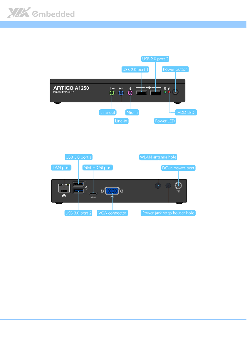
Front I/O panel
Front I/O panel
Front I/O panelFront I/O panel
3 X 3.5Ø Audio Jacks (Line-In, Line-Out and Mic-In)
2 x USB 2.0 ports
Power status LED indicator
HDD activity LED indicator
Power On/Off Switch
Rear I/O panel
Rear I/O panel
Rear I/O panelRear I/O panel
1 x Gigabit Ethernet port (1 x RJ-45)
2 x USB 3.0 ports
1 x VGA connector
1 x mini-HDMI®
1 x 3.5 Ø DC Jack Power Input connector
1 x Antenna hole reserve cutout to support WiFi networking via Cable connection
to EMIO-1533 WLAN module
1 x DC jack strap holder hole reserve cutout
WLAN
WLAN (optional)
(optional)
WLAN WLAN
(optional)(optional)
EMIO
EMIO----1533
1533
EMIOEMIO
15331533
1 x USB 820.11b/g/n WLAN connector on P910-C for VIA EmIO-1533 WLAN
connection
Power Supply
Power Supply
Power SupplyPower Supply
Power Input Connector
Power Input Connector
Power Input ConnectorPower Input Connector
1 x 3.5 Ø DC Jack connector via cable connect to P910 mainboard
Power Consumption
Power Consumption
Power ConsumptionPower Consumption
Maximum 30 W
Input Voltage
Input Voltage
Input VoltageInput Voltage
DC 12V Power Input
Mechanical Power Supply
Mechanical Power Supply
Mechanical Power SupplyMechanical Power Supply
Chassis Construction
Chassis Construction
Chassis ConstructionChassis Construction
Aluminum top cover chassis housing
Galvanized steel sheet (SECC) body chassis housing
Venting Holes
Venting Holes
Venting HolesVenting Holes
Stylish Venting holes on left & right pleat
Mounting
Mounting
MountingMounting
VESA mounting holes on bottom chassis
System Dimension
System Dimension
System DimensionSystem Dimension
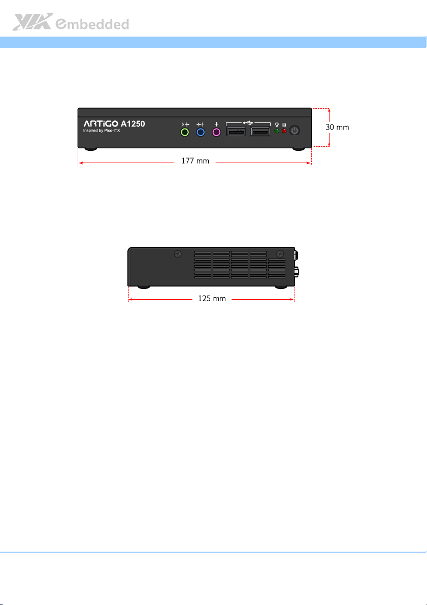
177 mm (w) x 30 mm (H) x 125 mm (D)
A1250 User Manual
User Manual
A1250A1250
User ManualUser Manual
5
Page 15
ARTiGO
Environmental Specification
Environmental Specification
Environmental SpecificationEnvironmental Specification
Operating Temperature
Operating Temperature
Operating TemperatureOperating Temperature
0°C up to 40°C for 1.2GHz VIA Eden® X4 (under working environment at PMON
ARTiGO----A1250
ARTiGOARTiGO
disable from P910 BIOS)
Storage Temperature
Storage Temperature
Storage TemperatureStorage Temperature
-10°C to 60°C
Relative Humidity
Relative Humidity
Relative HumidityRelative Humidity
0% ~ 90% @ 40°C, non-condensing
EMC Approved
EMC Approved
EMC ApprovedEMC Approved
Industrial PC, CE, FCC Class B
Safety
Safety
SafetySafety
CB/CCC
Software Compatibility (Operating System)
Software Compatibility (Operating System)
Software Compatibility (Operating System)Software Compatibility (Operating System)
Microsoft Windows 7
Microsoft Windows XP
Microsoft Windows XP Embedded Standard 2009
Microsoft Windows Embedded Standard 7
Embedded Linux
Reminder:
Reminder:
Reminder:Reminder:
1. The ambient temperature and the CPU loadings affect the system fan rpm. Therefore, the higher rpm
will generate higher fan noise (dB). The smart fan of ARTiGO-A1250 system runs at lowest speed
(default) at 25°C room temperature and when the CPU loading is less than 60%.
2. As the operating temperature provided in the specifications is a result of the test performed in VIA’s
chamber, a number of variables can influence this result. Please note that the working temperature may
vary depending on the actual situation and environment. It is highly suggested to execute a solid
testing and take all the variables into consideration when building the system. Please ensure that the
system runs well under the operating temperature in terms of application.
A1250 User Manual
User Manual
A1250A1250
User ManualUser Manual
6
Page 16
ARTiGO
ARTiGO----A1250
ARTiGOARTiGO
1.3. ARTiGO-A1250 Dimensions
Figure
Figure 1111: Dimensions of the ARTiGO
: Dimensions of the ARTiGO----A1250 (front view)
Figure Figure
: Dimensions of the ARTiGO: Dimensions of the ARTiGO
Figure
Figure 2222: Dimensions of the AR
: Dimensions of the ARTiGO
Figure Figure
: Dimensions of the AR: Dimensions of the AR
A1250 (front view)
A1250 (front view)A1250 (front view)
TiGO----A1250 (side view)
A1250 (side view)
TiGOTiGO
A1250 (side view)A1250 (side view)
A1250 User Manual
User Manual
A1250A1250
User ManualUser Manual
7
Page 17
ARTiGO
ARTiGO----A1250
ARTiGOARTiGO
1.4. ARTiGO-A1250 Layout
Figure
Figure 3333: Front Panel layout
: Front Panel layout
Figure Figure
: Front Panel layout: Front Panel layout
A1250 User Manual
User Manual
A1250A1250
User ManualUser Manual
Figure
Figure 4444: Rear Panel layout
: Rear Panel layout
Figure Figure
: Rear Panel layout: Rear Panel layout
8
Page 18
ARTiGO
2.
2. External I/O Pin Descriptions
External I/O Pin Descriptions
2.2.
External I/O Pin Descriptions External I/O Pin Descriptions
and Functionality
and Functionality
and Functionalityand Functionality
The VIA ARTiGO-A1250 has a wide selection of interfaces located on the
front and rear panels as part of the external I/O.
ARTiGO----A1250
ARTiGOARTiGO
A1250 User Manual
A1250A1250
User Manual
User ManualUser Manual
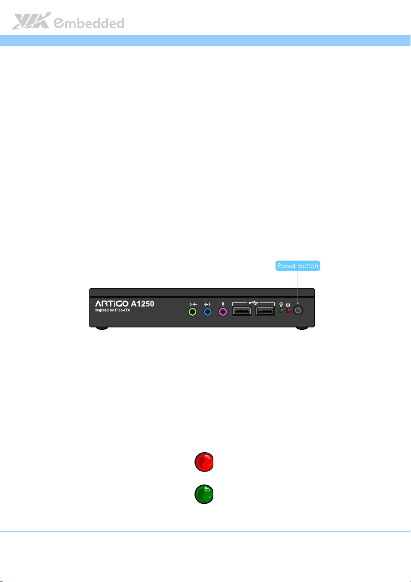
2.1. Front Panel
2.1.1. Power Button
The ARTiGO-1250 comes with a Power On/Off button, that supports Soft
Power-On/Off (Instant Off or 4 second delay) and Suspend.
Figure
Figure 5555: Power button switch diagram
: Power button switch diagram
Figure Figure
: Power button switch diagram: Power button switch diagram
2.1.2. LED Indicators (Power LED and HDD LED)
There are two LEDs on the front panel that indicate the system status:
PWR LED flashes in green and indicates the status of the system’s
power status.
HDD LED flashes in red and indicates any storage activity for the HDD.
Figure
Figure 6666: Power and HDD LED indicator diagrams
: Power and HDD LED indicator diagrams
Figure Figure
: Power and HDD LED indicator diagrams: Power and HDD LED indicator diagrams
9
Page 19
ARTiGO
ARTiGO----A1250
ARTiGOARTiGO
A1250 User Manual
A1250A1250
User Manual
User ManualUser Manual
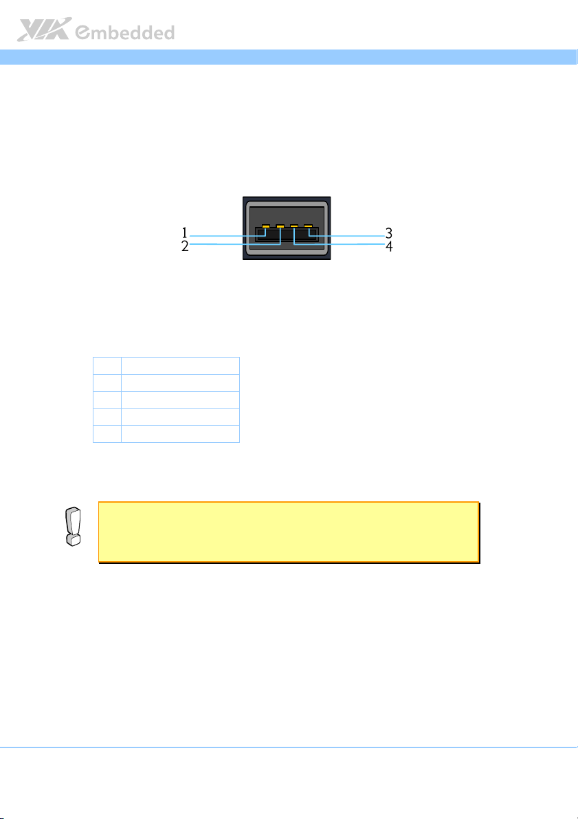
2.1.3. USB 2.0 Port
The ARTiGO-A1250 provides two USB 2.0 ports in the front panel for Plug &
Play and hot swapping access to external devices. The USB interface complies
with USB UHCI, Rev. 2.0.
Figure
Figure 7777: USB 2.0 port pinout diagram
: USB 2.0 port pinout diagram
Figure Figure
: USB 2.0 port pinout diagram: USB 2.0 port pinout diagram
Pin
Pin
Signal
Signal
PinPin
SignalSignal
1 VCC
2 USB_PO-
3 USB_PO+
4 GND
Table
Table 1111: USB 2.0 port pinout
: USB 2.0 port pinout
Table Table
: USB 2.0 port pinout: USB 2.0 port pinout
Reminder:
Reminder:
Reminder:Reminder:
1. The maximum power for both USB ports (together) is 2.5W.
2. Please reserve at least one USB port for keyboard or mouse usage.
10
Page 20
ARTiGO
ARTiGO----A1250
ARTiGOARTiGO
A1250 User Manual
A1250A1250
User Manual
User ManualUser Manual
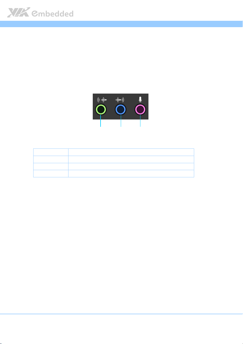
2.1.4. Audio Jacks
The ARTiGO-A1250 offers High Definition Audio through three 3.5 mm TRS
jack connectors: Line-in, Line-out and Mic-in.
The Line-In jack is for connecting an external audio devices such as CD player,
tape player and etc. The Line-out jack is for connecting to external speakers or
headphones. The Mic-in jack is for connecting to a microphone.
Figure
Figure 8888: Audio
: Audio jack receptacle stack diagram
Figure Figure
Jack
Jack Description
JackJack
Mic-In TRS jack, 3.5mm Ø 5P, 90 Degree, Female, shielded
Line-Out TRS jack, 3.5mm Ø 5P, 90 Degree, Female, shielded
Line-In TRS jack, 3.5mm Ø 5P, 90 Degree, Female, shielded
Table
Table 2222: Audio jack receptacle description
Table Table
jack receptacle stack diagram
: Audio : Audio
jack receptacle stack diagramjack receptacle stack diagram
: Audio jack receptacle description
: Audio jack receptacle description: Audio jack receptacle description
Line-out Line-in Mic-in
Description
DescriptionDescription
11
Page 21

ARTiGO
ARTiGO----A1250
ARTiGOARTiGO
A1250 User Manual
A1250A1250
User Manual
User ManualUser Manual
2.2. Rear Panel
2.2.1. Power Input (DC-In) Jack
The ARTiGO-A1250 comes with a DC power input jack on the real panel that
carries 12V
Figure
Figure 9999: Power input jack diagram
Figure Figure
Table
Table 3333: Power input jack pinout
Table Table
. External power input.
DC
: Power input jack diagram
: Power input jack diagram: Power input jack diagram
Pin
Pin Sig
PinPin
1 GND
2 12VDC
: Power input jack pinout
: Power input jack pinout: Power input jack pinout
Signal
nal
SigSig
nalnal
12
Page 22

ARTiGO
ARTiGO----A1250
ARTiGOARTiGO
A1250 User Manual
A1250A1250
User Manual
User ManualUser Manual
2.2.2. LAN Port: Gigabit Ethernet
The ARTiGO-A1250 system is equipped with one Gigabit Ethernet port (LAN1)
on rear panel. The port is fully compliant with IEEE 802.3 (10BASE-T), 802.3u
(100BASE-TX), and 802.3ab (1000BASE-T) standards. The pinout of the LAN1
port is shown below
Figure
Figure 10
10: Gigabit Ethernet port pinout diagram
Figure Figure
Table
Table 4444: Gigabit Ethernet port pinout
Table Table
: Gigabit Ethernet port pinout diagram
1010
: Gigabit Ethernet port pinout diagram: Gigabit Ethernet port pinout diagram
LAN1
LAN1
LAN1LAN1
Pin
Pin Signal
Signal
PinPin
SignalSignal
1 LAN1_TD0+
2 LAN1_TD0-
3 LAN1_TD1+
4 LAN1_TD1-
5 LAN1_TD2+
6 LAN1_TD2-
7 LAN1_TD3+
8 LAN1_TD3-
: Gigabit Ethernet port pinout
: Gigabit Ethernet port pinout: Gigabit Ethernet port pinout
The LAN port (RJ-45) has two individual LED indicators located on the front
side to show its Active/Link status and Speed status.
Link LED
(Left LED on RJ
(Left LED on RJ----45 connector)
(Left LED on RJ(Left LED on RJ
Link Off Off Off
Speed_10Mbit The LED is always On in either Green
or Orange colors
Speed_100Mbit The LED is always On in Green color Flash in Yellow color
Speed_1000Mbit The LED is always On in Orange color Flash in Yellow color
Table
Table 5555: Gigabit Ethernet LED color definition
: Gigabit Ethernet LED color definition
Table Table
: Gigabit Ethernet LED color definition: Gigabit Ethernet LED color definition
13
Link LED
Link LEDLink LED
45 connector)
45 connector)45 connector)
Active LED
Active LED
Active LEDActive LED
(Right LED on RJ
(Right LED on RJ----45 connector)
(Right LED on RJ(Right LED on RJ
Flash in Yellow color
45 connector)
45 connector)45 connector)
Page 23

ARTiGO
ARTiGO----A1250
ARTiGOARTiGO
A1250 User Manual
A1250A1250
User Manual
User ManualUser Manual
2.2.3. USB 3.0 Port
The ARTiGO-1250 is equipped with two USB 3.0 ports, also known as
SuperSpeed USB. The USB 3.0 port has a maximum data transfer rate up to 5
Gbps and offers a backwards compatible with previous USB 2.0 specifications.
It gives complete Plug and Play and hot swap capability for external devices.
The pinout of the typical USB 3.0 port is shown below.
Figure
Figure 11
11: USB 3.0 port pinout diagram
Figure Figure
Table
Table 6666: USB 3.0 port pinout
Table Table
: USB 3.0 port pinout diagram
1111
: USB 3.0 port pinout diagram: USB 3.0 port pinout diagram
Pin
Pin
Signal
Signal
PinPin
SignalSignal
1 +5V
2 Data-
3 Data+
4 Ground
5 Rx-
6 Rx+
7 Ground
8 Tx-
9 Tx+
: USB 3.0 port pinout
: USB 3.0 port pinout: USB 3.0 port pinout
14
Page 24

ARTiGO
ARTiGO----A1250
ARTiGOARTiGO
A1250 User Manual
A1250A1250
User Manual
User ManualUser Manual
2.2.4. VGA Connector
The ARTiGO-A1250 provides a high resolution VGA interface through a 15-pin
D-sub female connector to support analog VGA monitors. It supports up to
2560 x 1600 @ 60Hz resolution and up to 512 MB shared memory.
Figure
Figure 12
12: VGA connector pinout diagram
Figure Figure
Table
Table 7777: VGA connector pinout
Table Table
: VGA connector pinout diagram
1212
: VGA connector pinout diagram: VGA connector pinout diagram
Pin
Pin
Signal
Signal
PinPin
SignalSignal
1 Red
2 Green
3 Blue
4 NC
5 GND
6 GND
7 GND
8 GND
9 NC
10 GND
11 NC
12 DDC DAT
13 H-SYNC
14 V-SYNC
15 DDC CLK
: VGA connector pinout
: VGA connector pinout: VGA connector pinout
15
Page 25

ARTiGO
ARTiGO----A1250
ARTiGOARTiGO
A1250 User Manual
User Manual
A1250A1250
User ManualUser Manual
2.2.5. Mini HDMI
®
Port
The integrated 19-pin HDMI® port uses an HDMI® Type C connector as
®
defined in the HDMI
®
HDMI
displays. The pinout of the Mini HDMI® port is shown below.
specification. The Mini-HDMI® port is for connecting to
Figure
Figure 13
13: Mini HDMI
Figure Figure
1313
: Mini HDMI
: Mini HDMI: Mini HDMI
®®®®
port pinout diagram
port pinout diagram
port pinout diagram port pinout diagram
Pin
Pin
Signal
Table
Table 8888: Mini
: Mini----HDMI
Table Table
: Mini: Mini
Signal Pin
PinPin
SignalSignal
1 TMDS Data2 Shield 2 TMDS Data2+
3 TMDS Data2– 4 TMDS Data1 Shield
5 TMDS Data1+ 6 TMDS Data1–
7 TMDS Data0 Shield 8 TMDS Data0+
9 TMDS Data0– 10 TMDS Clock Shield
11 TMDS Clock+ 12 TMDS Clock–
13 DDC/CEC Ground 14 CEC
15 SCL 16 SDA
17 Reserved (N.C. on
device)
19 Hot Plug Detect
®®®®
HDMI
port pinout
port pinout
HDMIHDMI
port pinout port pinout
Pin
Signal
Signal
PinPin
SignalSignal
18 +5V Power
16
Page 26

ARTiGO
3.
3. Hardware Installation
Hardware Installation
3.3.
Hardware InstallationHardware Installation
This chapter provides you with information about hardware installation
procedures. It is recommended to use a grounded wrist strap before handling
computer components. Electrostatic discharge (ESD) can damage some
components.
ARTiGO----A1250
ARTiGOARTiGO
A1250 User Manual
A1250A1250
User Manual
User ManualUser Manual
3.1. Installing the Rubber Feet and Memory
Step 1
At the bottom side of ARTiGO-1250, attach carefully each rubber foot to the
designated area then firmly press it down to ensure the rubber foot is properly
in place.
17
Page 27

ARTiGO
ARTiGO----A1250
ARTiGOARTiGO
A1250 User Manual
A1250A1250
User Manual
User ManualUser Manual
Step 2
Remove the two screws from the memory access cover then gently lift up the
cover. Flip over the memory access cover and remove the memory thermal
pad plastic cover.
Step 3
Gently insert the DDR3 memory module into the SODIMM socket at 30
degrees angle. Push down the memory module until it snaps into place.
18
Page 28

ARTiGO
ARTiGO----A1250
ARTiGOARTiGO
A1250 User Manual
A1250A1250
Step 4
Reinstall the memory access cover and secure it with two screws.
User Manual
User ManualUser Manual
19
Page 29

ARTiGO
ARTiGO----A1250
ARTiGOARTiGO
A1250 User Manual
A1250A1250
User Manual
User ManualUser Manual
3.2. Installing 2.5 inch SATA Hard Disk Drive
Step 1
Remove the six screws of the top cover from both sides and bottom side of
the chassis. Slightly pull the cover horizontally then gently pull up the cover.
Step 2
Unscrew the hard disk bracket tray.
20
Page 30

ARTiGO
ARTiGO----A1250
ARTiGOARTiGO
A1250 User Manual
A1250A1250
User Manual
User ManualUser Manual
Step 3
Pull out the hard disk bracket tray. Then remove the cover plastic of the hard
disk thermal pad.
Step 4
Flip over the hard disk drive and install it to the hard disk bracket tray over the
thermal pad. Make sure the plastic cover of the thermal pad has been
removed before installing the hard disk. Then secure the hard disk with four
screws.
21
Page 31

ARTiGO
ARTiGO----A1250
ARTiGOARTiGO
A1250 User Manual
A1250A1250
User Manual
User ManualUser Manual
Step 5
Gently slide back the bracket tray with the 2.5 inch hard disk. Ensure that no
wiring has been pinched while reinstalling the bracket tray. Secure the bracket
tray with screw.
Step 6
Connect the SATA cable (power and data) to the hard disk drive.
22
Page 32

ARTiGO
ARTiGO----A1250
ARTiGOARTiGO
A1250 User Manual
A1250A1250
User Manual
User ManualUser Manual
3.3. Installing the WLAN kit
Step 1
Remove the antenna WLAN hole cover at the back panel of ARTiGO-1250.
Install the WLAN module and secure it with two screws.
Step 2
Remove the P910-D bridge board connector.
23
Page 33

ARTiGO
ARTiGO----A1250
ARTiGOARTiGO
A1250 User Manual
A1250A1250
User Manual
User ManualUser Manual
Step 3
Attach the WLAN cable to the WLAN module. Then attach the other end of
the cable to the P910-C daughter board. The WLAN cable must be layout
underneath the P910-D bridge board connector before reinstalling the P910-D
bridge board connector.
Reminder:
Reminder:
Reminder:Reminder:
Be sure to install the P910-D bridge board connector in the correct orientation. The top marking
“P910-D” should be on the top side as indicated in the figure.
24
Page 34

ARTiGO
ARTiGO----A1250
ARTiGOARTiGO
A1250 User Manual
A1250A1250
User Manual
User ManualUser Manual
Step 4
Insert the WLAN port connector into the antenna hole from the inside of the
chassis. Insert the washer, fasten it with the nut and install the external antenna.
Gently connect the mini coaxial cable of the WLAN port connector to the
mini RF connector on the WLAN module.
25
Page 35

ARTiGO
ARTiGO----A1250
ARTiGOARTiGO
A1250 User Manual
A1250A1250
User Manual
User ManualUser Manual
3.4. Installing the Power DC Jack Strap Holder
Step 1
Prepare the DC jack strap holder. The DC jack strap holder consists of two
parts: Slide strap tie and jack holder.
Note:
Note:
Note:Note:
The Jack holder has locking clip that controls the locking and releasing of the jack holder. Slightly
pulling the locking clip will unlock the jack holder from the rail of slide strap tie.
Step 2
Remove the DC jack strap holder hole cover (rubber) at the back panel of the
chassis. The hole is located between the antenna hole and DC-In power port.
26
Page 36

ARTiGO
ARTiGO----A1250
ARTiGOARTiGO
A1250 User Manual
A1250A1250
User Manual
User ManualUser Manual
Step 3
Insert the strap cable tie into the hole. Ensure the strap cable tie is fully
inserted in vertical position and the slide rails are facing the left side as
indicated in the figure.
Step 4
Attach the jack holder to the DC jack cable.
27
Page 37

ARTiGO
ARTiGO----A1250
ARTiGOARTiGO
A1250 User Manual
A1250A1250
User Manual
User ManualUser Manual
Step 5
Insert the slide strap tie into the side of the jack.
Step 6
Slide in deeply the jack holder until the power DC jack reaches the DC-in
power port. Then connect the DC jack into the DC-in power port.
28
Page 38

ARTiGO
4.
4. BIOS Setup Utility
BIOS Setup Utility
4.4.
BIOS Setup UtilityBIOS Setup Utility
ARTiGO----A1250
ARTiGOARTiGO
4.1. Entering the BIOS Setup Utility
A1250 User Manual
User Manual
A1250A1250
User ManualUser Manual
Power on the computer and press Delete
sequence to enter the BIOS Setup Utility. If the entry point has passed, restart
the system and try again.
Delete during the beginning of the boot
DeleteDelete
4.2. Control Keys
Up
Up Move up one row
UpUp
Down
Down Move down one row
DownDown
Left
Left Move to the left in the navigation bar
LeftLeft
Right
Right Move to the right in the navigation bar
RightRight
Enter
Enter Access the highlighted item / Select the item
EnterEnter
Esc
Esc Jumps to the Exit screen or returns to the previous screen
EscEsc
++++1 Increase the numeric value
1
Decrease the numeric value
----
2
F1
F1 General help
F1F1
F2
F2 Previous value
F2F2
F3
F3 Load optimized defaults
F3F3
F4
F4 Save all the changes and exit
F4F4
Note:
Note:
Note:Note:
1. Must be pressed using the 10-key pad.
2. The General help contents are only for the Status Page and Option Page setup menus.
29
Page 39

ARTiGO
ARTiGO----A1250
ARTiGOARTiGO
4.3. Getting Help
A1250 User Manual
User Manual
A1250A1250
User ManualUser Manual
The BIOS Setup Utility provides a “General Help
accessed at any time by pressing F1
using and navigating the BIOS Setup Utility. Press Esc
General Help” screen. This screen can be
General HelpGeneral Help
F1. The help screen displays the keys for
F1F1
Esc to exit the help screen.
EscEsc
30
Page 40

ARTiGO
ARTiGO----A1250
ARTiGOARTiGO
A1250 User Manual
A1250A1250
User Manual
User ManualUser Manual
4.4. System Overview
The System Overview screen is the default screen that is shown when the
BIOS Setup Utility is launched. This screen can be accessed by traversing the
navigation bar to the “Main” label.
Figure
Figure 14
14: Illustration of the Main menu screen
Figure Figure
: Illustration of the Main menu screen
1414
: Illustration of the Main menu screen: Illustration of the Main menu screen
4.4.1. BIOS Information
The content in this section of the screen shows the information about the
vendor, the Core version, UEFI specification version, the project version and
date & time of the project build.
4.4.2. Memory Information
This section shows the amount of memory that is installed on the hardware
platform.
4.4.3. System Language
This option allows the user to configure the language that the user wants to
use.
31
Page 41

ARTiGO
ARTiGO----A1250
ARTiGOARTiGO
A1250 User Manual
A1250A1250
User Manual
User ManualUser Manual
4.4.4. System Date
This section shows the current system date. Press Tab
Shift+Tab
Shift+Tab to traverse left through the month, day, and year segments. The ++++
Shift+TabShift+Tab
and ---- keys on the number pad can be used to change the values. The weekday
name is automatically updated when the date is altered. The date format is
[Weekday, Month, Day, Year].
Tab to traverse right and
TabTab
4.4.5. System Time
This section shows the current system time. Press Tab
Shift+Tab
Shift+Tab to traverse left through the hour, minute, and second segments. The
Shift+TabShift+Tab
++++ and ---- keys on the number pad can be used to change the values. The time
format is [Hour : Minute : Second].
Tab to traverse right and
TabTab
32
Page 42

ARTiGO
ARTiGO----A1250
ARTiGOARTiGO
A1250 User Manual
A1250A1250
User Manual
User ManualUser Manual
4.5. Advanced Settings
The Advanced Settings screen shows a list of categories that can provide
access to a sub-screen. Sub-screen links can be identified by the preceding
right-facing arrowhead.
Figure
Figure 15
15: Illustration of the Advanced Settings screen
Figure Figure
: Illustration of the Advanced Settings screen
1515
: Illustration of the Advanced Settings screen: Illustration of the Advanced Settings screen
The Advanced Settings screen contains the following links:
ACPI Settings
S5 RTC Wake Settings
CPU Configuration
SATA Configuration
F81801 H/W Monitor
Clock Generator Configuration
Onboard Configuration
33
Page 43

ARTiGO
ARTiGO----A1250
ARTiGOARTiGO
A1250 User Manual
A1250A1250
User Manual
User ManualUser Manual
4.5.1. ACPI Settings
ACPI grants the operating system direct control over system power
management. The ACPI Configuration screen can be used to set a number of
power management related functions.
Figure
Figure 16
16: Illustration of the ACPI Settings screen
Figure Figure
: Illustration of the ACPI Settings screen
1616
: Illustration of the ACPI Settings screen: Illustration of the ACPI Settings screen
4.5.1.1.
4.5.1.1. Enable Hibernation
4.5.1.1.4.5.1.1.
Enable/disable system ability to Hibernate.
4.5.1.2.
4.5.1.2. ACPI Sleep State
4.5.1.2.4.5.1.2.
Select the highest ACPI sleep state the system will enter when the SUSPEND
button is selected. Available options are: Suspend Disabled / S1 only(CPU
Stop Clock) /S3 only(Suspend to RAM) / Both S1 and S3 available for OS to
choose from.
Enable Hibernation
Enable HibernationEnable Hibernation
ACPI Sleep State
ACPI Sleep StateACPI Sleep State
34
Page 44

ARTiGO
ARTiGO----A1250
ARTiGOARTiGO
A1250 User Manual
A1250A1250
User Manual
User ManualUser Manual
4.5.2. S5 RTC Wake Settings
Figure
Figure 17
17: Illustration of the
Figure Figure
4.5.2.1.
4.5.2.1. Wake system with Fixed Time
4.5.2.1.4.5.2.1.
: Illustration of the S5 RTC
1717
: Illustration of the : Illustration of the
Wake system with Fixed Time
Wake system with Fixed TimeWake system with Fixed Time
Enable or disable system wake on alarm event. When enabled, system will
wake on the hr:min:sec specified.
S5 RTC Wake Settings screen
Wake Settings screen
S5 RTC S5 RTC
Wake Settings screenWake Settings screen
4.5.2.2.
4.5.2.2. Wake system with Dynamic Time
4.5.2.2.4.5.2.2.
Wake system with Dynamic Time
Wake system with Dynamic TimeWake system with Dynamic Time
Enable or disable Wake system with Dynamic Time.
35
Page 45

ARTiGO
ARTiGO----A1250
ARTiGOARTiGO
A1250 User Manual
A1250A1250
User Manual
User ManualUser Manual
4.5.3. CPU Configuration
The CPU Configuration screen shows detailed information about the built-in
processor. In addition to the processor information, the thermal controls can
be set.
Figure
Figure 18
18: Illust
: Illustration of
ration of CPU
CPU Configuration screen
Figure Figure
1818
: Illust: Illust
ration of ration of
Configuration screen
CPUCPU
Configuration screen Configuration screen
4.5.3.1.
4.5.3.1. TM3
4.5.3.1.4.5.3.1.
TM3
TM3TM3
The TM3 Function has two settings: Disabled and Enabled. When the setting is
changed to “Disabled”, the CPU’s built-in thermal sensor will not function.
When the setting is changed to “Enabled”, the thermal sensor will
automatically adjust the CPU ratio and V CORE to prevent the CPU from
overheating.
36
Page 46

ARTiGO
ARTiGO----A1250
ARTiGOARTiGO
A1250 User Manual
A1250A1250
User Manual
User ManualUser Manual
4.5.4. SATA Configuration
The SATA Configuration screen allows the user to view and configure the
settings of the SATA configuration settings.
Figure
Figure 19
19: Illustration of SATA Configuration screen
Figure Figure
4.5.4.1.
4.5.4.1. SATA Mode
4.5.4.1.4.5.4.1.
: Illustration of SATA Configuration screen
1919
: Illustration of SATA Configuration screen: Illustration of SATA Configuration screen
SATA Mode
SATA ModeSATA Mode
This option allows the user to manually configure SATA controller for a
particular mode.
IDE Mode
IDE Mode
IDE ModeIDE Mode
Set this value to change the SATA to IDE mode.
AHCI Mode
AHCI Mode
AHCI ModeAHCI Mode
Set this value to change the SATA to AHCI mode.
37
Page 47

ARTiGO
ARTiGO----A1250
ARTiGOARTiGO
A1250 User Manual
A1250A1250
User Manual
User ManualUser Manual
4.5.5. PC Health Status
The PC Health Status screen has no editable fields. The system temperature is
taken from an optional sensor that is connected to the J5 pin header.
Figure
Figure 20
20: Illustration of PC Health Status screen
Figure Figure
: Illustration of PC Health Status screen
2020
: Illustration of PC Health Status screen: Illustration of PC Health Status screen
38
Page 48

ARTiGO
ARTiGO----A1250
ARTiGOARTiGO
A1250 User Manual
A1250A1250
User Manual
User ManualUser Manual
4.5.6. Clock Generator Configuration
The Clock Generator Configuration screen enables access to the Spread
Spectrum Setting feature.
Figure
Figure 21
21: Illustration of Clock Generator Configuration screen
Figure Figure
: Illustration of Clock Generator Configuration screen
2121
: Illustration of Clock Generator Configuration screen: Illustration of Clock Generator Configuration screen
4.5.6.1.
4.5.6.1. CPU Spread Spectrum
4.5.6.1.4.5.6.1.
The Spread Spectrum Setting feature enables the BIOS to modulate the clock
frequencies originating from the mainboard. The settings are in percentages of
modulation. Higher percentages result in greater modulation of clock
frequencies. This feature has 3 options: Disabled, +-0.25% and -0.5%.
4.5.6.2.
4.5.6.2. PCIe Spread Spectrum
4.5.6.2.4.5.6.2.
Select PCIe Spread Spectrum. This feature has 2 options: Disabled and -0.5%.
CPU Spread Spectrum
CPU Spread SpectrumCPU Spread Spectrum
PCIe Spread Spectrum
PCIe Spread SpectrumPCIe Spread Spectrum
39
Page 49

ARTiGO
ARTiGO----A1250
ARTiGOARTiGO
A1250 User Manual
A1250A1250
User Manual
User ManualUser Manual
4.5.7. OnBoard Device Configuration
The OnBoard Device Configuration screen has the following features.
Figure
Figure 22
22: Illust
: Illustration of OnBoard Device Configuration screen
Figure Figure
4.5.7.1.
4.5.7.1. OnBoard LAN Enable
4.5.7.1.4.5.7.1.
The OnBoard LAN Enable feature determines whether the onboard LAN
controller will be used or not.
ration of OnBoard Device Configuration screen
2222
: Illust: Illust
ration of OnBoard Device Configuration screenration of OnBoard Device Configuration screen
OnBoard LAN Enable
OnBoard LAN EnableOnBoard LAN Enable
4.5.7.2.
4.5.7.2. EuP/ErP Lot6 support
4.5.7.2.4.5.7.2.
The EuP/ErP Lot6 Support feature enables the BIOS to reduce the power draw
to less than 1W when the system is in standby mode. This feature has two
options: enabled and disabled.
4.5.7.3.
4.5.7.3. S5 Wakeup On LAN
4.5.7.3.4.5.7.3.
The S5 Wakeup On LAN feature enables the BIOS to allow remote wake-up
from the S5 power off state through the PCI bus.
EuP/ErP Lot6 support
EuP/ErP Lot6 supportEuP/ErP Lot6 support
S5 Wakeup On LAN
S5 Wakeup On LANS5 Wakeup On LAN
40
Page 50

ARTiGO
4.5.7.4.
4.5.7.4. Eup/Erp Lot6
4.5.7.4.4.5.7.4.
The EuP/ErP Lot6 Support feature enables the BIOS to reduce the power draw
to less than 1W when the system is in standby mode. This feature has two
options: enabled and disabled.
Eup/Erp Lot6 Support
Eup/Erp Lot6 Eup/Erp Lot6
Support
SupportSupport
ARTiGO----A1250
ARTiGOARTiGO
A1250 User Manual
A1250A1250
User Manual
User ManualUser Manual
41
Page 51

ARTiGO
ARTiGO----A1250
ARTiGOARTiGO
A1250 User Manual
A1250A1250
User Manual
User ManualUser Manual
4.6. Chipset Settings
The Chipset Settings screen shows a list of categories that can provide access
to a sub-screen. Sub-screen links can be identified by the preceding right-
facing arrowhead.
Figure
Figure 23
23: Illustration of Chipset Settings screen
Figure Figure
: Illustration of Chipset Settings screen
2323
: Illustration of Chipset Settings screen: Illustration of Chipset Settings screen
The Chipset Settings screen contains the following links:
DRAM Configuration
Video Configuration
PMU-ACPI Configuration
Others Configuration
42
Page 52

ARTiGO
ARTiGO----A1250
ARTiGOARTiGO
A1250 User Manual
A1250A1250
User Manual
User ManualUser Manual
4.6.1. DRAM Configuration
The DRAM Configuration screen has two features for controlling the system
DRAM. All other DRAM features are automated and cannot be accessed.
Figure
Figure 24
24: Illustration of DRAM Configuration screen
FigureFigure
: Illustration of DRAM Configuration screen
2424
: Illustration of DRAM Configuration screen: Illustration of DRAM Configuration screen
4.6.1.1.
4.6.1.1. DRAM Clock
4.6.1.1.4.6.1.1.
DRAM Clock
DRAM ClockDRAM Clock
The DRAM Clock option enables the user to determine how the BIOS handles
the memory clock frequency. The memory clock can either be dynamic or
static. This feature has eleven options.
By SPD
By SPD
By SPDBy SPD
By SPD option enables the BIOS to select a compatible clock frequency for
the installed memory.
400 MHz
400 MHz
400 MHz400 MHz
The 400 MHz option forces the BIOS to be fixed at 800 MHz for DDR3
memory modules.
43
Page 53

ARTiGO
533 MHz
533 MHz
533 MHz533 MHz
ARTiGO----A1250
ARTiGOARTiGO
A1250 User Manual
A1250A1250
User Manual
User ManualUser Manual
The 533 MHz option forces the BIOS to be fixed at 1066 MHz for DDR3
memory modules.
566 MHz
566 MHz
566 MHz566 MHz
The 566 MHz option forces the BIOS to be fixed at 1132 MHz for DDR3
memory modules.
600 MHz
600 MHz
600 MHz600 MHz
The 600 MHz option forces the BIOS to be fixed at 1200 MHz for DDR3
memory modules.
633 MHz
633 MHz
633 MHz633 MHz
The 633 MHz option forces the BIOS to be fixed at 1266 MHz for DDR3
memory modules.
667 MHz
667 MHz
667 MHz667 MHz
The 667 MHz option forces the BIOS to be fixed at 1334 MHz for DDR3
memory modules.
700 MHz
700 MHz
700 MHz700 MHz
The 700 MHz option forces the BIOS to be fixed at 1400 MHz for DDR3
memory modules
733 MHz
733 MHz
733 MHz733 MHz
The 733 MHz option forces the BIOS to be fixed at 1466 MHz for DDR3
memory modules
766 MHz
766 MHz
766 MHz766 MHz
The 766 MHz option forces the BIOS to be fixed at 1532 MHz for DDR3
memory modules
800 MHz
800 MHz
800 MHz800 MHz
The 800 MHz option forces the BIOS to be fixed at 1600 MHz for DDR3
memory modules
44
Page 54

ARTiGO
4.6.1.2.
4.6.1.2. VGA Share Memory (Frame Buffer)
4.6.1.2.4.6.1.2.
The VGA Share Memory feature enables the user to choose the amount of the
system memory to reserve for use by the integrated graphics controller. The
selections of memory amount that can be reserved are 256MB, 512MB and
1024MB.
VGA Share Memory (Frame Buffer)
VGA Share Memory (Frame Buffer)VGA Share Memory (Frame Buffer)
ARTiGO----A1250
ARTiGOARTiGO
A1250 User Manual
A1250A1250
User Manual
User ManualUser Manual
45
Page 55

ARTiGO
ARTiGO----A1250
ARTiGOARTiGO
A1250 User Manual
A1250A1250
User Manual
User ManualUser Manual
4.6.2. Video Configuration
The Video Configuration screen has features for controlling the integrated
graphics controller in the VX11H chipset.
Figure
Figure 25
25: Illustration of Video Configuration screen
Figure Figure
4.6.2.1.
4.6.2.1. Select Display Device
4.6.2.1.4.6.2.1.
Available selections are: Auto and Manual.
: Illustration of Video Configuration screen
2525
: Illustration of Video Configuration screen: Illustration of Video Configuration screen
Select Display Device Control
Select Display DeviceSelect Display Device
Control
Control Control
4.6.2.2.
4.6.2.2. Select Display Device 1 and 2
4.6.2.2.4.6.2.2.
The Select Display Device feature enables the user to choose a specific
display interface. This feature has two options: CRT and HDMI. If both Select
Display Device 1 and Select Display Device 2 are set to the same interface,
then any display device connected to the other interface will not function. For
example, if both Select Display 1 and 2 are set to CRT, then no data will be
sent to the HDMI port.
Select Display Device 1 and 2
Select Display Device 1 and 2Select Display Device 1 and 2
46
Page 56

ARTiGO
ARTiGO----A1250
ARTiGOARTiGO
A1250 User Manual
A1250A1250
User Manual
User ManualUser Manual
4.6.3. PMU_ACPI Configuration
The PMU_ACPI Configuration screen can be used to set a number of power
management related functions.
Figure
Figure 26
26: Illustration of PMU_ACPI Configuration screen
Figure Figure
4.6.3.1.
4.6.3.1. Other Control
4.6.3.1.4.6.3.1.
: Illustration of PMU_ACPI Configuration screen
2626
: Illustration of PMU_ACPI Configuration screen: Illustration of PMU_ACPI Configuration screen
Other Control
Other ControlOther Control
Figure
Figure 27
27: Illustration of Oth
Figure Figure
: Illustration of Other Control screen
2727
: Illustration of Oth: Illustration of Oth
er Control screen
er Control screener Control screen
47
Page 57

ARTiGO
ARTiGO----A1250
ARTiGOARTiGO
A1250 User Manual
A1250A1250
User Manual
User ManualUser Manual
4.6.3.1.1.
4.6.3.1.1. AC Loss Auto
4.6.3.1.1.4.6.3.1.1.
AC Loss Auto----restart
AC Loss AutoAC Loss Auto
restart
restartrestart
AC Loss Auto-restart defines how the system will respond after AC power has
been interrupted while the system is on. There are three options.
Power Off
Power Off
Power OffPower Off
The Power Off option keeps the system in an off state until the power button
is pressed again.
Power On
Power On
Power OnPower On
The Power On option restarts the system when the power has returned.
Last State
Last State
Last StateLast State
The Last State option restores the system to its previous state when the power
was interrupted.
4.6.3.1.2.
4.6.3.1.2. USB S4 WakeUp
4.6.3.1.2.4.6.3.1.2.
USB S4 WakeUp
USB S4 WakeUpUSB S4 WakeUp
The USB S4 WakeUp enables the system to resume through the USB device
port from S4 state. There are two options: “Enabled” or “Disabled”.
48
Page 58

ARTiGO
ARTiGO----A1250
ARTiGOARTiGO
A1250 User Manual
A1250A1250
4.6.4. Others Configuration
The Others Configuration screen can be used to set Watchdog Timer
Configuration and Keyboard/Mouse Wakeup Configuration.
Figure
Figure 28
28: Illustration of Others Configuration screen
Figure Figure
: Illustration of Others Configuration screen
2828
: Illustration of Others Configuration screen: Illustration of Others Configuration screen
User Manual
User ManualUser Manual
4.6.4.1.
4.6.4.1. WATCHDOG Timer Enable
4.6.4.1.4.6.4.1.
When this feature is enabled, an embedded timing device automatically
prompts corrective action upon system malfunction detection.
4.6.4.2.
4.6.4.2. Keyboard/Mouse Wak
4.6.4.2.4.6.4.2.
When this feature is enabled, pressing any key of the keyboard or moving the
mouse can wake up the system from suspend.
WATCHDOG Timer Enable
WATCHDOG Timer EnableWATCHDOG Timer Enable
Keyboard/Mouse Wakeup Control
Keyboard/Mouse WakKeyboard/Mouse Wak
eup Control
eup Controleup Control
49
Page 59

ARTiGO
ARTiGO----A1250
ARTiGOARTiGO
4.7. Boot Settings
A1250 User Manual
User Manual
A1250A1250
User ManualUser Manual
The Boot Settings screen has a single link that goes to the Boot Configuration
and Boot Option Priorities
Boot Option Priorities screens.
Boot Option PrioritiesBoot Option Priorities
Figure
Figure 29
29: Illustration of Boot Settings screen
Figure Figure
: Illustration of Boot Settings screen
2929
: Illustration of Boot Settings screen: Illustration of Boot Settings screen
Boot Configuration
Boot ConfigurationBoot Configuration
4.7.1. Boot Configuration
The Boot Settings Configuration screen has several features that can be run
during the system boot sequence.
4.7.1.1.
4.7.1.1. Quiet Boot
4.7.1.1.4.7.1.1.
Quiet Boot
Quiet BootQuiet Boot
The Quiet Boot feature hides all of the Power-on Self Test (POST) messages
during the boot sequence. Instead of the POST messages, the user will see an
OEM logo. This feature has two options: enabled and disabled.
50
Page 60

ARTiGO
ARTiGO----A1250
ARTiGOARTiGO
4.7.2. Boot Option Priorities
The Boot Option Priorities screen lists all bootable devices.
4.7.2.1.
4.7.2.1. Launch PXE OpROM policy
4.7.2.1.4.7.2.1.
Do not launch
Do not launch
Do not launchDo not launch
Prevent the option for Legacy Network Device.
Legacy only
Legacy only
Legacy onlyLegacy only
Allow the option for Legacy Network Device.
Launch PXE OpROM policy
Launch PXE OpROM policyLaunch PXE OpROM policy
A1250 User Manual
User Manual
A1250A1250
User ManualUser Manual
51
Page 61

ARTiGO
ARTiGO----A1250
ARTiGOARTiGO
A1250 User Manual
A1250A1250
User Manual
User ManualUser Manual
4.8. Save & Exit
The Save & Exit Configuration screen has the following features:
Figure
Figure 30
30: Illustration of Save & Exit screen
Figure Figure
4.8.1. Save Changes and Exit
Save all changes to the BIOS and exit the BIOS Setup Utility. The “F10” hotkey
can also be used to trigger this command.
: Illustration of Save & Exit screen
3030
: Illustration of Save & Exit screen: Illustration of Save & Exit screen
4.8.2. Discard Changes and Exit
Exit the BIOS Setup Utility without saving any changes. The “Esc” hotkey can
also be used to trigger this command.
4.8.3. Save Changes and Reset
Save all changes to the BIOS and reboot the system. The new system
configuration parameters will take effect.
52
Page 62

ARTiGO
ARTiGO----A1250
ARTiGOARTiGO
A1250 User Manual
A1250A1250
User Manual
User ManualUser Manual
4.8.4. Discard Changes and Reset
This command reverts all changes to the settings that were in place when the
BIOS Setup Utility was launched. The “F7” hotkey can also be used to trigger
this command.
4.8.5. Save Options
Save Changes done so far to any of the setup options.
4.8.6. Save Changes
Save system configuration and continue. For some of the options it required to
reset the system to take effect.
4.8.7. Discard Changes
Undo the previous changes.
4.8.8. Restore Defaults
Restore default values for all setup options.
53
Page 63

ARTiGO
5.
5. Driver Installation
Driver Installation
5.5.
Driver InstallationDriver Installation
ARTiGO----A1250
ARTiGOARTiGO
A1250 User Manual
A1250A1250
User Manual
User ManualUser Manual
5.1. Microsoft Driver Support
The VIA ARTiGO-A1250 mainboard is compatible with Microsoft operating
systems. The latest Windows drivers can be downloaded from the VIA
Embedded website at www.viaembedded.com.
For embedded operating systems, the related drivers can be found in the VIA
Embedded website at www.viaembedded.com.
5.2. Linux Driver Support
The VIA ARTiGO-A1250 mainboard is highly compatible with many Linux
distributions.
Support and drivers are provided through various methods including:
Drivers provided by VIA
Using a driver built into a distribution package
Visiting www.viaembedded.com for the latest updated drivers
Installing a third party driver (such as the ALSA driver from the
Advanced Linux Sound Architecture project for integrated audio)
For OEM clients and system integrators developing a product for long term
production, other code and resources may also be made available. Contact
VIA Embedded to submit a request.
54
Page 64

 Loading...