

Page 1
1 2
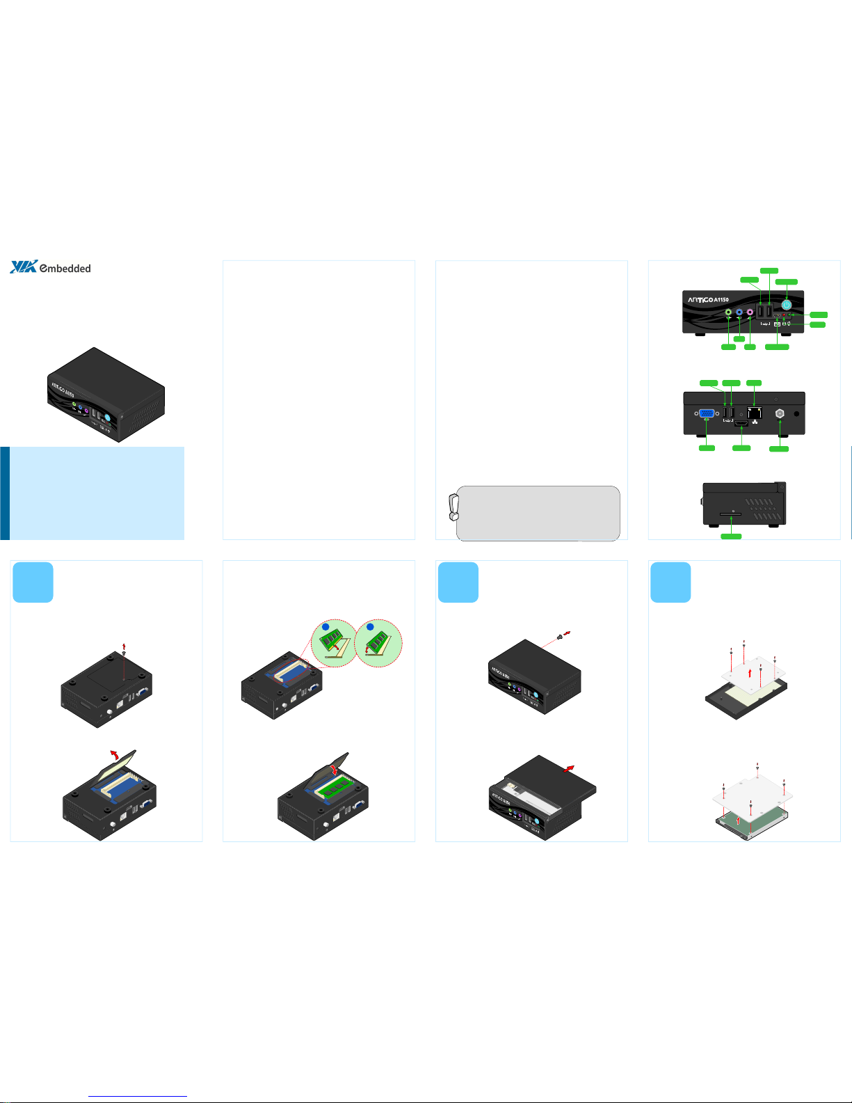
HDMI
DC IN 12V
Power port
VGA port
USB port 4
USB port 3
LAN port
HDMI port
5
Inspired by Pico-ITX
Power button
Mini USB port
USB port 2
USB port 1
HDD LED
Power LED
Mic-in
Line-in
Line-out
ARTiGO-A1150
Quick Guide
Key Features:
• Space saving, ultra compact design
• Onboard Gigabit Ethernet
• Four USB 2.0 host and one USB Device port
• One HDMI® and one VGA ports
• One drive bay for 2.5-inch SATA hard disk drive or SSD
• SD card reader and WLAN module (optional)
The ARTiGO-A1150 is an ultra compact embedded system. It’s based
on the VIA EPIA-P900 Pico-ITX form factor and powered by a high
performance VIA Eden™ X2 processor. The ARTiGO-A1150 is de-
signed with elegant chassis with dual I/O access plates for easy inte-
gration and quick setup.
Packing List:
•
1 x ARTiGO-A1150 system
•
1 x AC-to-DC adapter, DC 12V/5A, 60W
•
1 x Power cable, 180 cm
•
1 x Quick Guide
Important:
Please ensure that all items in the packing list are present before using
this product. If any of the items are missing or damaged, contact your
distributor or sales representative immediately.
Hard disk drive, CompactFlash disk, Flash SSD drive, SD card reader
module and SD card, wireless LAN module, system memory module
and operating system must be purchased separately.
2
Step 3
Insert the memory module into the SODIMM socket at the 45
degree angle. Then push down until the memory module snaps
into place. The SODIMM socket has two locking mechanisms that
will click once the memory module has been fully inserted.
Step 1
Locate the memory access cover on the bottom side of the
ARTiGO-A1150 and remove the screw.
1
Step 2
Remove the memory access cover as indicated in the figure below.
Installing the Memory
Step 4
Reinstall the memory access cover and secure it with screw.
Step 1
Remove the screw of the top cover from the rear side of the
ARTiGO-A1150.
Step 2
Then gently slide the top cover backward and lift off the top
cover as indicated in the figure below.
Rear I/O Layout
Side I/O Layout
Step 1
On the bottom side of the top cover, remove the SATA 2.5” hard
disk cover plate by unscrewing the four screws.
3
Installing the
SATA 2.5” Hard Disk
Step 2
Attach the hard disk plate to the 2.5-inch SATA hard disk by
aligning the mounting holes on the SATA 2.5” hard disk with the
mounting holes on the hard disk cover plate. Then secure the
hard disk in place with four screws.
Front I/O Layout
P/N: 99G51-013094-10
SD
SD Card slot
Specifications:
•
CPU:
VIA Eden™ X2 1.0GHz processor (800 MHz FSB)
•
System Chipset:
VIA VX900 Unified Digital Media IGP chipset
•
System Memory:
1 x DDR3 1066 MHz SDRAM SODIMM slot
•
Supports memory sizes up to 4 GB
•
Graphics:
Integrated VIA C-9 HCM DX9 3D/2D AGP graphics with MPEG-2,
H.264 and WMV9/VC1 video decoding accelerator
•
Storage:
•
1 x 2.5-inch SATA hard disk drive bay
•
1 x SD card reader (optional)
•
LAN:
VIA VT6130G Gigabit Ethernet controller
•
Audio:
VIA VT2021 High Definition Audio Codec
•
System Indicator:
•
Power Status (green LED)
•
Hard Disk Drive Activity (red LED)
•
BIOS:
AMI BIOS
•
8 Mbit LPC Flash Memory
•
Front I/O:
•
2 x USB 2.0 host ports
•
1 x USB device port
•
3 x Audio jacks (Line-out, Line-in & Mic-in)
•
Rear I/O:
•
1 x VGA connector
•
2 x USB 2.0 host ports
•
1 x HDMI® port
•
1 x RJ45 port (Gigabit Ethernet connection)
•
DC 12V Power Input connector
•
Side I/O
•
1 x SD slot (optional)
•
Dimensions:
146 mm (W) x 52 mm (H) x 99 mm (D)
•
Weight:
0.6 Kg (1.32 lbs)
•
Operating Temperature:
0°C up to 45°C
•
Storage Temperature:
-
10°C ~ 60°C
•
Humidity:
0% ~ 90% relative humidity (non-condensing) @ 45°C
Opening the
Top Cover Chassis
Page 2
1
1
1
1
1
2
3
1
2
VIA Technologies, Inc.
1F, 531, Zhong-zheng Road,
Xindian District, New Taipei
City 231, Taiwan
Tel: 886-2-2218-5452
Fax: 886-2-2218-5453
Web: www.via.com.tw
Copyright © 2013 VIA Technologies, Inc. All rights reserved.
For more information on this and other
VIA products, please visit
www.viaembedded.com
For further support and service, please
visit www.via.com.tw
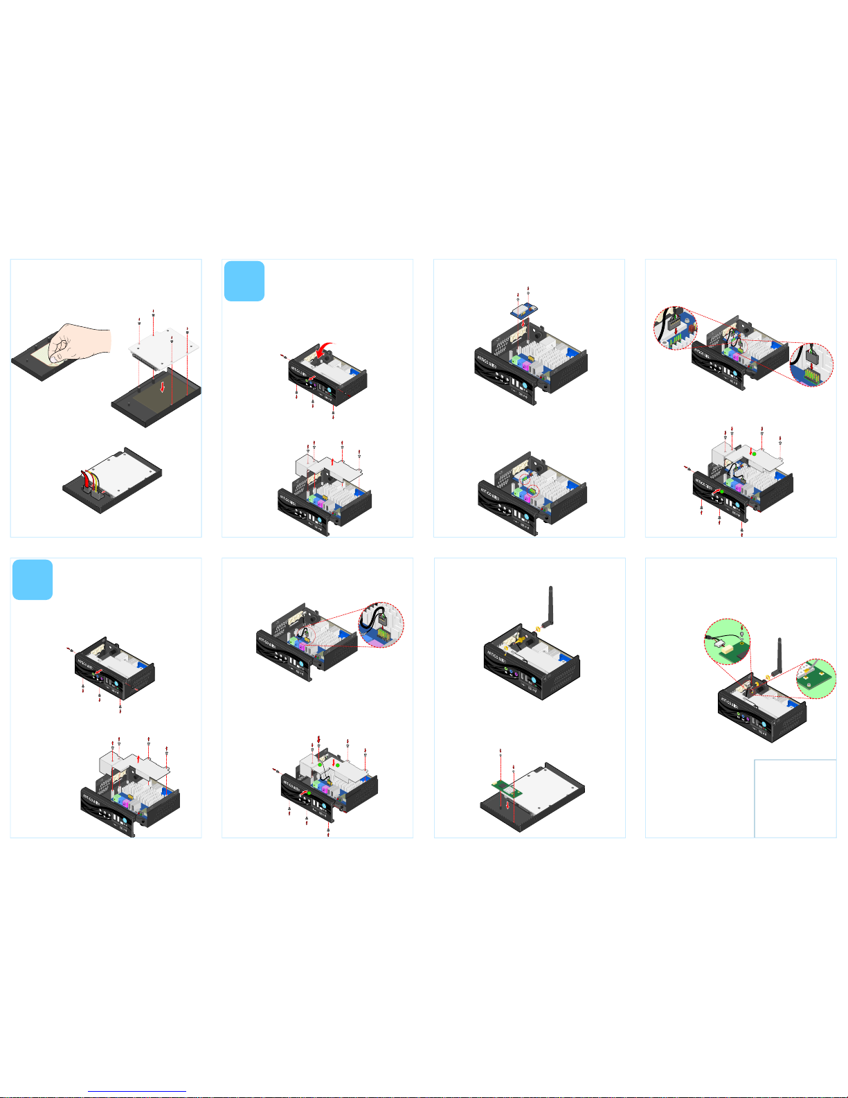
Step 3
Remove the protective (plastic) layer of the hard disk thermal
pad. Then reinstall the hard disk plate by aligning the cover plate
with the mounting holes under the top cover and secure it with
four screws.
Step 7
Connect the WLAN USB cable to the mini connector on the
WLAN module and the grounding cable to the screw area. Then
connect the WLAN antenna cable to the micro RF connector on
the WLAN USB module (EMIO-1530 or EMIO-1533) as indicated
in the figure below.
Step 4
Connect the SATA power and SATA data cables to the hard disk.
Step 5
Replace the top cover onto the ARTiGO-A1150.
5
Step 8
Reinstall the top cover of the ARTiGO-A1150.
4
Step 1
Locate the mounting area of SD card reader. Remove the five
screws in order to remove the front panel plate.
Step 2
Remove the fan duct as indicted in the figure below.
Step 3
Mount the SD card reader module (EMIO-5130) and secure it
with two screws.
Step 4
Locate the SD card reader pin headers on the SD card reader
module (EMIO-5130) and on the P820-B daughter card.
Step 1
Remove the top cover and the front panel plate by unscrewing
the five screws as indicated in the figure.
Step 5
Gently connect the SD card reader cable to the pin header on the SD
card reader module (EMIO-5130) and to the pin header on the P820-B
daughter card.
Step 6
Mount the WLAN USB module (EIMO-1530 or EMIO-1533) on
the bottom side of chassis top cover with two screws.
Step 5
Locate the WLAN antenna hole at the rear side of the chassis and
install the WLAN antenna.
Step 3
Locate the WLAN pin header on the P820-B daughter card. Then
gently connect the WLAN USB cable to the pin header on the
P820-B daughter card.
Step 4
Make sure that the WLAN USB cable is properly routed
underneath the fan duct before reinstalling it. Connect the
grounding cable to one of the screws of the fan duct as indicated
in the figure below. Then attach the front panel plate and secure
it with screws.
Step 2
Remove the four screws indicated by the red arrows and carefully
lift the fan duct off the board.
Step 6
Properly route the SD card reader cable underneath the fan duct. Then
reinstall the fan duct and front panel plate.
1
1
Installing the
WLAN Kit
Installing the
SD Card Reader
 Loading...