

Page 1

Revision
1.04
104-11232010-1056
user manual
ARTiGO-A1100
Barebone System with
EPIA-P820 Embedded Board
Page 2
Copyright and Trademarks
Copyright © 2010 VIA Technologies Incorporated. All rights reserved.
No part of this document may be reproduced, transmitted, transcribed, stored in a
retrieval system, or translated into any language, in any form or by any means, electronic,
mechanical, magnetic, optical, chemical, manual or otherwise without the prior written
permission of VIA Technologies, Incorporated.
All trademarks are the property of their respective holders.
PS/2 is a registered trademark of IBM Corporation.
Disclaimer
No license is granted, implied or otherwise, under any patent or patent rights of VIA
Technologies. VIA Technologies makes no warranties, implied or otherwise, in regard to
this document and to the products described in this document. The information provided
in this document is believed to be accurate and reliable as of the publication date of this
document. However, VIA Technologies assumes no responsibility for the use or misuse of
the information in this document and for any patent infringements that may arise from the
use of this document. The information and product specifications within this document are
subject to change at any time, without notice and without obligation to notify any person
of such change.
Regulatory Compliance
FCC-A Radio Frequency Interference Statement
This equipment has been tested and found to comply with the limits for a class B digital
device, pursuant to part 15 of the FCC rules. These limits are designed to provide
reasonable protection against harmful interference when the equipment is operated in a
commercial environment. This equipment generates, uses, and can radiate radio
frequency energy and, if not installed and used in accordance with the instruction manual,
may cause harmful interference to radio communications. Operation of this equipment in a
residential area is likely to cause harmful interference, in which case the user will be
required to correct the interference at his personal expense.
Notice 1
The changes or modifications not expressly approved by the party responsible for
compliance could void the user's authority to operate the equipment.
Notice 2
Shielded interface cables and A.C. power cord, if any, must be used in order to comply
with the emission limits.
Tested To Comply
With FCC Standards
FOR HOME OR OFFICE USE
Battery Recycling and Disposal
Only use the appropriate battery specified for this product.
Do not re-use, recharge, or reheat an old battery.
Do not attempt to force open the battery.
Do not discard used batteries with regular trash.
Discard used batteries according to local regulations.
II
Page 3

Safety Precautions
Do’s
o Always read the safety instructions carefully.
o Keep this User's Manual for future reference.
o All cautions and warnings on the equipment should be
noted.
o Keep this equipment away from humidity.
o Lay this equipment on a reliable flat surface before setting
it up.
o Make sure the voltage of the power source and adjust
properly 110/220V before connecting the equipment to the
power inlet.
o Place the power cord in such a way that people cannot
step on it.
o Always unplug the power cord before inserting any add-on
card or module.
o If any of the following situations arises, get the equipment
checked by authorized service personnel:
o The power cord or plug is damaged.
o Liquid has penetrated into the equipment.
o The equipment has been exposed to moisture.
o The equipment has not worked well or you cannot
get it work according to User's Manual.
o The equipment has dropped and damaged.
o The equipment has obvious sign of breakage.
Don’ts
o Do not leave this equipment in an environment
unconditioned or in a storage temperature above 60°C
(140°F). The equipment may be damaged.
o Do not leave this equipment in direct sunlight.
o Never pour any liquid into the opening. Liquid can cause
damage or electrical shock.
o Do not place anything over the power cord.
o Do not cover the ventilation holes. The openings on the
enclosure protect the equipment from overheating
III
Page 4

IV
Box Contents
1 x ARTiGO-A1100 system
1 x "Drivers and Utility" CD disc
1 x AC-to-DC adapter, DC 12V/5A, 60W
1 x Power cable, 180 cm, USA type
Page 5

V
Ordering Information
Model Number Description
ATG-1100-1N12A1 VIA Nano™ 1.2GHz Processor based
Embedded System, with 1 x VGA, 1 x
HDMI, HD Audio (Line-in, Line-out and Micin), 1 x GigaLAN, 4 x USB 2.0 1 x USB
device, DC-In 12V
Optional Accessories
Power Cord
99G33-02034C Power cord with PSE mark, 180 cm
99G33-02033C Power cord, 180 cm, Europe type
99G33-02031C Power cord, 180 cm, UK type
SD Card Reader
EMIO-5130-00A1 1 x slot SD card reader
WLAN Module
EMIO-1530-80A1 802.11 b/g Wireless LAN USB Module for
EMIO-1530-90A1 802.11 b/g Wireless LAN USB Module for
for Japan market
USA
Europe
Page 6

T
ABLE OF
C
ONTENTS
1 Product Overview............................................................................................... 1
Key Features...........................................................................................................2
Specifications ......................................................................................................... 4
ARTiGO-A1100 Dimensions...........................................................................7
2 Front, Rear and Side I/O Pin Descriptions and Functionality........ 9
Front I/O Layout ................................................................................................10
Rear I/O Layout ..................................................................................................10
Side I/O Layout...................................................................................................10
I/O Pin Description ...........................................................................................11
Power Button.................................................................................................11
LED Indicators (Power LED and HDD LED) ...................................11
USB device port.............................................................................................11
USB 2.0 ports..................................................................................................11
Audio Ports (Line-out, Line-in and Mic-in)........................................12
VGA Port ..........................................................................................................12
HDMI Port ........................................................................................................13
LAN Port ...........................................................................................................13
Power Input (DC-In) Port..........................................................................13
3 Basic installation .................................................................................................15
Installing the memory .....................................................................................16
Opening the Top Cover Chassis ................................................................19
Installing the SATA 2.5” Hard Disk ............................................................20
Installing the SD Card Reader .....................................................................24
Installing the WLAN kit ...................................................................................28
Installing VESA Mount Bracket ...................................................................32
4 BIOS Setup............................................................................................................35
Entering the BIOS Setup Menu ..................................................................36
Control Keys .........................................................................................................36
Getting Help ........................................................................................................37
Main Menu ...........................................................................................................38
AMIBIOS............................................................................................................38
Processor ..........................................................................................................38
System Memory.............................................................................................38
System Time ....................................................................................................38
System Date ....................................................................................................38
Advanced Settings............................................................................................39
CPU Configuration ......................................................................................39
VI
Page 7

IDE Configuration ........................................................................................39
ACPI Configuration .....................................................................................39
APM Configuration .....................................................................................39
Spread Spectrum Configuration...........................................................39
USB Configuration.......................................................................................39
CPU Configuration ...........................................................................................40
CMPXCHG8B instruction support........................................................40
Nano CPU Thermal Monitor Adjust....................................................40
IDE Configuration .............................................................................................41
Parallel ATA IDE Controller......................................................................41
Hard Disk Write Protect ............................................................................41
IDE Detect Time Out (Sec).......................................................................41
ATA(PI) 80Pin Cable Detection .............................................................41
IDE Drives..............................................................................................................42
Primary IDE Master ......................................................................................42
Primary IDE Slave (SATA Device)..........................................................42
Type.....................................................................................................................43
LBA/Large Mode..........................................................................................43
Block (Multi-Sector Transfer)....................................................................43
PIO Mode.........................................................................................................43
DMA Mode .....................................................................................................43
S.M.A.R.T............................................................................................................43
32Bit Data Transfer......................................................................................43
ACPI Settings........................................................................................................44
General ACPI Configuration...................................................................44
Advanced ACPI Configuration ..............................................................44
Chipset ACPI Configuration ....................................................................44
General ACPI Configuration ........................................................................45
Suspend Mode ..............................................................................................45
Repost Video on S3 Resume ..................................................................45
Advanced ACPI Configuration ...................................................................46
ACPI Version Features ...............................................................................46
ACPI APIC Support.......................................................................................46
AMI OEMB Table..........................................................................................46
Headless Mode..............................................................................................46
Chipset ACPI Configuration .........................................................................47
USB Device Wakeup Function..............................................................47
APM Configuration...........................................................................................48
Power Management / APM ...................................................................48
Power Button Mode...................................................................................48
Suspend Power Saving Type..................................................................48
Restore on AC / Power Loss ...................................................................48
Manual Throttle Ratio.................................................................................48
System Thermal .............................................................................................49
VII
Page 8

Standby Time Out........................................................................................49
Suspend Time Out.......................................................................................49
Hard Disk Time Out (Minute).................................................................49
Green PC Monitor Power State.............................................................49
Video Power Down Mode......................................................................49
Hard Disk Power Down Mode .............................................................49
Display Activity...............................................................................................49
Monitor IRQ3~15.........................................................................................49
Resume on Ring............................................................................................50
Resume on PME#.........................................................................................50
Resume On PS/2 KBC ................................................................................50
Wake-up Key ..................................................................................................50
Resume on PS/2 Mouse............................................................................50
Resume on RTC Alarm...............................................................................50
Spread Spectrum Configuration ................................................................51
Spread Spectrum Configuration...........................................................51
USB Configuration ............................................................................................52
USB 1.1 Ports Configuration ...................................................................52
USB 2.0 Ports Enable ..................................................................................52
USB Device Mode Enable........................................................................52
Legacy USB Support...................................................................................52
USB 2.0 Controller Mode .........................................................................52
BIOS EHCI Hand-Off ...................................................................................52
Advanced PCI/PnP Settings..........................................................................53
Clear NVRAM .................................................................................................53
Plug & Play O/S.............................................................................................53
PCI Latency Timer.........................................................................................53
Allocate IRQ to PCI VGA...........................................................................53
Palette Snooping ..........................................................................................53
PCI IDE BusMaster........................................................................................54
Off Board PCI/ISA IDE Card ....................................................................54
IRQ3~15 ...........................................................................................................54
DMA Channel 0~7 .....................................................................................54
Reserved Memory Size...............................................................................54
Boot Settings........................................................................................................55
Boot Settings Configuration....................................................................55
Boot Device Priority.....................................................................................55
Boot Settings Configuration.........................................................................56
Quick Boot.......................................................................................................56
Display Logo...................................................................................................56
AddOn ROM Display Mode....................................................................56
Bootup Num-Lock .......................................................................................56
PS/2 Mouse Support...................................................................................56
Wait For ‘F1’ If Error....................................................................................56
VIII
Page 9

Hit ‘DEL’ Message Display........................................................................56
Interrupt 19 Capture...................................................................................57
Boot Device Priority ..........................................................................................58
1st Boot Device .............................................................................................58
Security Settings..................................................................................................59
Change Supervisor Password ................................................................59
Change User Password ............................................................................59
Boot Sector Virus Protection...................................................................59
Advanced Chipset Settings...........................................................................60
North Bridge VIA VX855 Configuration...........................................60
South Bridge VIA VX855 Configuration...........................................60
North Bridge VIA VX855 Configuration................................................61
Software Reset E2 Issue.............................................................................61
Change DCLK using RDCKM .................................................................61
Dynamic CKE..................................................................................................61
NB Performance Register .........................................................................61
NB Energy Saving Register......................................................................61
OnChip VGA Configuration ........................................................................62
VGA Frame Buffer Size..............................................................................62
CPU Direct Access Frame Buffer ..........................................................62
Select Display Device..................................................................................62
Panel Type .......................................................................................................62
Dithering ..........................................................................................................62
Backlight Control ..........................................................................................62
South Bridge VIA VX855 Configuration ................................................63
Parallel Channel Enable ............................................................................63
ISA Master Support......................................................................................63
High Definition Audio................................................................................63
Enable Embedded COM..........................................................................63
PCI Debug Master Mode..........................................................................63
SMBus Multi-Master.....................................................................................63
PCI VCC33 Leakage Patch.......................................................................63
PCI Delay Transaction ................................................................................64
WATCH-DOG ................................................................................................64
Exit Options ..........................................................................................................65
Save Changes and Exit ..............................................................................65
Discard Changes and Exit........................................................................65
Discard Changes ..........................................................................................65
Load Optimal Defaults...............................................................................65
5 Driver Installation...............................................................................................67
Driver Utilities.......................................................................................................68
Getting Started ..............................................................................................68
Running the Driver Utilities CD .............................................................68
CD Content ..........................................................................................................69
IX
Page 10

1
Product Overview
1
Page 11

The ARTiGO-A1100 is an ultra compact embedded system. Its
based on the VIA EPIA-P820 Pico-ITX form factor board and
powered by high performance VIA Nano 1.2 GHz processor. The
ARTiGO-A1100 chassis is designed with dual-sided I/O access
plates for easy integration.
The mechanical parts in the ARTiGO-A1100 consist of a system
chassis, removable top cover and front faceplate. The ARTiGOA1100 comes with built-in SATA data and power cables for 2.5”
SATA hard disks. The ARTiGO-A1100 is also available with an
optional SD card reader and WLAN (wireless LAN) module.
KEY FEATURES
UUUUltra compact chassis for the
ltra compact chassis for the EPIA
ltra compact chassis for the ltra compact chassis for the
The ARTiGO-A1100 houses the VIA EPIA-P820 Pico-ITX form factor
board with a maximum height of 56 mm, width of 99 mm and
length of 146 mm. The ARTiGO-A1100 chassis is rugged
aluminum case, design to ensure maximum reliability.
SSSSmall and
mall and sssstylish design
mall and mall and
The ARTiGO-A1100 housing is composed of three mechanical
parts: the chassis, removable top cover and front faceplate. Its
space saving design enables it to be installed in space critical
environments.
tylish design
tylish designtylish design
EPIA----P820
P820
EPIAEPIA
P820P820
Optimized integration with front and rear I/O access
Optimized integration with front and rear I/O access
Optimized integration with front and rear I/O accessOptimized integration with front and rear I/O access
Front and rear I/O access enables the ARTiGO-A1100 to easily
supports various applications as well as for easy integration and
quick setup.
Quick Data Transmission by USB
Quick Data Transmission by USB ddddevice port
Quick Data Transmission by USB Quick Data Transmission by USB
The ARTiGO-A1100 comes with one USB device port that allows
ARTiGO-A1100 as a USB Client device for user friendly and quick
data transfer to another computer.
Display Acceleration
Display Acceleration
Display AccelerationDisplay Acceleration
The ARTiGO-A1100 supports hardware acceleration of MPEG-2/4,
WMV9 and H.264 for 1080p full HD display
Shock Resistant
Shock Resistant
Shock ResistantShock Resistant
The ARTiGO-A1100 is shock resistant to 20G for maximum
reliability.
evice port
evice portevice port
2
Page 12

Networking
Networking support
Networking Networking
The ARTiGO-A1100 is equipped with an RJ-45 port that supports
Gigabit Ethernet. The ARTiGO-A1100 also has a WLAN module
option that gives the ARTiGO-A1100 freedom of WiFi access.
Embedded OS
Embedded OS rrrready
Embedded OS Embedded OS
The ARTiGO-A1100 is 100% compatible with several operating
systems including Microsoft Widows XP, Windows XP Embedded,
and Ubuntu Linux. ARTiGO-A1100 is also well suited to the
newest Microsoft operating system which is the Windows 7.
support
supportsupport
eady
eadyeady
3
Page 13

SPECIFICATIONS
CPU
Processor Core
Logic System
System Memory
Graphic
Gigabit Ethernet
Audio
CPU
CPUCPU
• VIA Nano 1.2 GHz processor
• NanoBGA2 package
• 800 MHz Front Side Bus speed
• 1 MB L2 Cache memory
System Chipset
System Chipset
System ChipsetSystem Chipset
• VIA VX855 Unified Digital Media IGP chipset
BIOS
BIOS
BIOSBIOS
• AMI BIOS
• 4Mbit LPC Flash Memory
System Power Management
System Power Management
System Power ManagementSystem Power Management
• Times Power On
• ACPI Supported
Technology
Technology
TechnologyTechnology
• One DDR2 533/667/800 MHz SDRAM SODIMM slot
Maximum Capacity
Maximum Capacity
Maximum CapacityMaximum Capacity
• Supports memory sizes up to 2 GB
Controller
Controller
ControllerController
• Integrated VIA Chrome9 HCM DX9 3D/2D Graphics and
Video Processor
• Integrated Unified Video Decoding Accelerator for
MPEG-2/4, H.264 and WMV9
Display M
Display Memory
Display MDisplay M
• Optimized Shared Memory Architecture (UMA), supports
up to 256 MB frame buffer using system memory
CRT Interface
CRT Interface
CRT InterfaceCRT Interface
• Supports one VGA connector
• Pixel resolution support up 1920 x 1200
HDMI Interface
HDMI Interface
HDMI InterfaceHDMI Interface
• Supports one HDMI port
Dual Independent
Dual Independent Display
Dual IndependentDual Independent
• Supports CRT + HDMI at the same resolutions, pixel
depths, and refresh rates
Controller
Controller
ControllerController
• Onboard VIA VT6122 Gigabit Ethernet controllers
Interface
Interface
InterfaceInterface
• One RJ-45 connector
• Supports Wake On LAN (WOL)
Controller
Controller
ControllerController
• VIA VT1708S High Definition Audio Codec
Interface
Interface
InterfaceInterface
• Support three 3.5Ø Audio jacks (Line-in, Line-out, and Mic-in)
emory
emoryemory
Display
Display Display
4
Page 14

USB 2.0
Storage
Interface
System Indicator
Watchdog Timer
I/O connectors
Power Supply
UUUUSB
SB 2.0
2.0 ports
ports
SBSB
2.0 2.0
ports ports
• Supports four USB 2.0 ports
• Supports one USB device port
Hard Disk Drive
Hard Disk Drive
Hard Disk DriveHard Disk Drive
• One 2.5-inch hard disk drive bay supports 2.5-inch SATA
interface HDD and Flash SSD
SD
SD
SDSD
• Reserve space for optional support of one SD card by
EMIO-5130 (optional) SD card reader
Power Status LED
Power Status LED
Power Status LEDPower Status LED
• One green color LED
HDD Activity LED
HDD Activity LED
HDD Activity LEDHDD Activity LED
• One red color LED
Output
Output
OutputOutput
• System reset
Interval
Interval
IntervalInterval
• Programmable 1~255 sec.
Front I/O
Front I/O
Front I/OFront I/O
• Two USB 2.0 host ports
• One USB device port
• Three 3.5Ø Audio jacks support
• Line-in, Line-out and Mic.-in
Rear
Rear I/O
I/O
Rear Rear
I/OI/O
• One VGA connector (D-Sub 15-pin female connector)
• Two USB 2.0 host ports
• One HDMI connector
• One RJ-45 connector for Gigabit Ethernet connection
Left I/O
Left I/O
Left I/O Left I/O
• One SD slot for SD card (optional)
Power Consumption
Power Consumption
Power ConsumptionPower Consumption
• Typical 12.84W, Maximum 20.72W
Input Voltage
Input Voltage
Input VoltageInput Voltage
• DC 12V Power Input
• Typical Power Input: 12VDC @ 1.07A
Power Input Connector
Power Input Connector
Power Input ConnectorPower Input Connector
• DC Power Input connector by DC Jack connector
Fuse Rating
Fuse Rating
Fuse RatingFuse Rating
• 7A @ 125V
5
Page 15

Mechanical
Environment
Specifications
Software
Compatibility
Construction
Construction
ConstructionConstruction
• Aluminum Chassis Housing
Mounting
Mounting
MountingMounting
•Optional Wall/VESA dual function mouting bracket
Dimension (W x H x D)
Dimension (W x H x D)
Dimension (W x H x D)Dimension (W x H x D)
• 146 mm x 52 mm x 99 mm
Weight
Weight
WeightWeight
• 0.6 Kg (1.32 lbs)
Operating
Operating Temperature
OperatingOperating
• 0°C to 45°C
Storage
Storage Temperature
StorageStorage
• -10°C to 60°C
Operatin
Operatingggg HHHHumidity
OperatinOperatin
• 0% ~ 90% @ 45°C, relative humidity, non-condensing
Vibration loading during operation
Vibration loading during operation
Vibration loading during operationVibration loading during operation
• 0.6Grms, IEC 60068-2-64, random, 5~500Hz, 1 Oct./min,
1hr/axis
Shock during operation
Shock during operation
Shock during operationShock during operation
• 20G, IEC 60068-2-27, half size, 11ms duration
EMC appr
EMC approved
EMC apprEMC appr
• CE, FCC Class B
Operating System
Operating System
Operating SystemOperating System
• Microsoft Widows XP, Windows 7
• Windows XP Embedded, Ubuntu Linux
Temperature
TemperatureTemperature
Temperature
TemperatureTemperature
umidity
umidityumidity
oved
ovedoved
6
Page 16
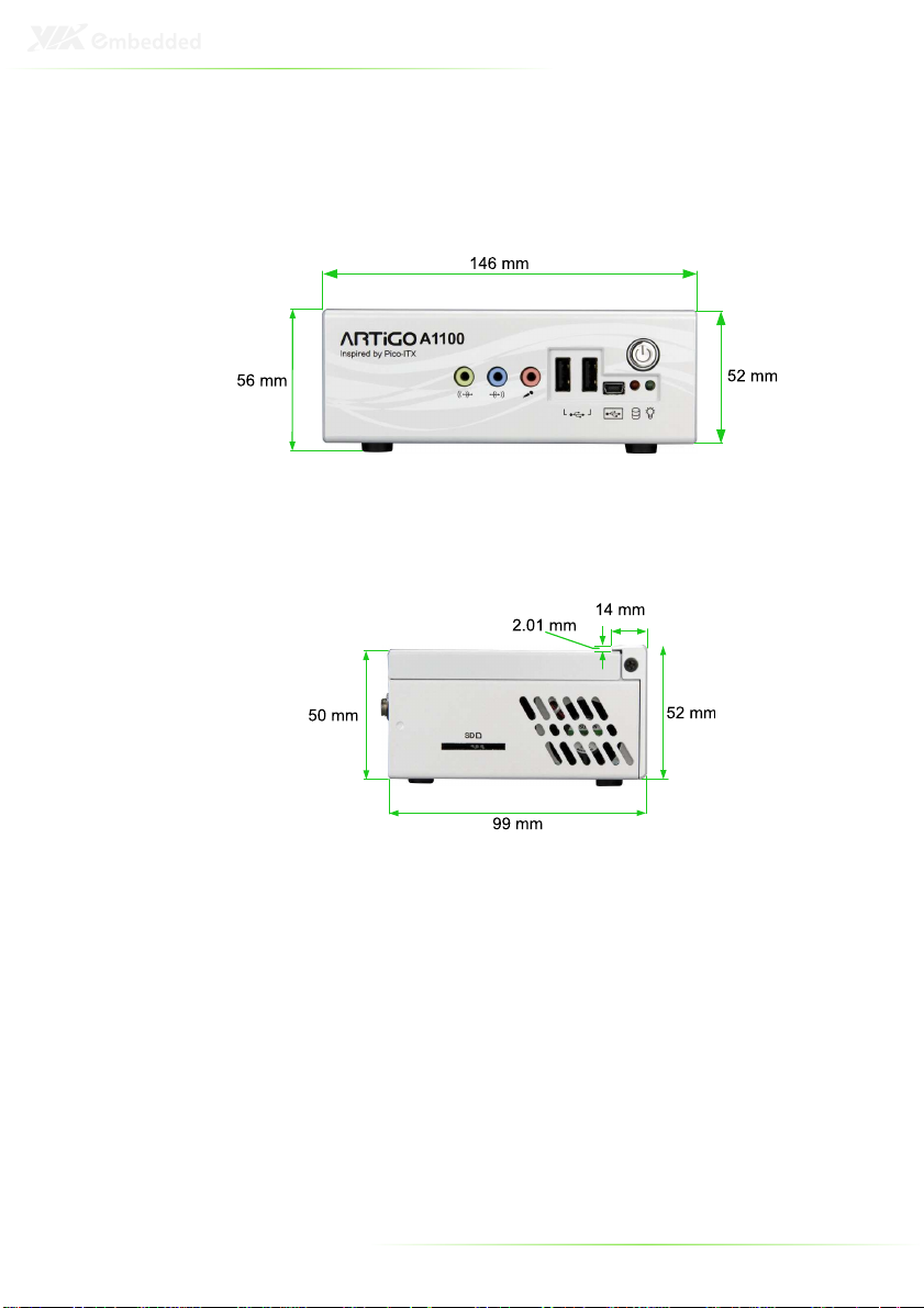
ARTIGO-A1100 DIMENSIONS
7
Page 17

8
Page 18

2
Front, Rear and Side
I/O Pin Descriptions
and Functionality
9
Page 19
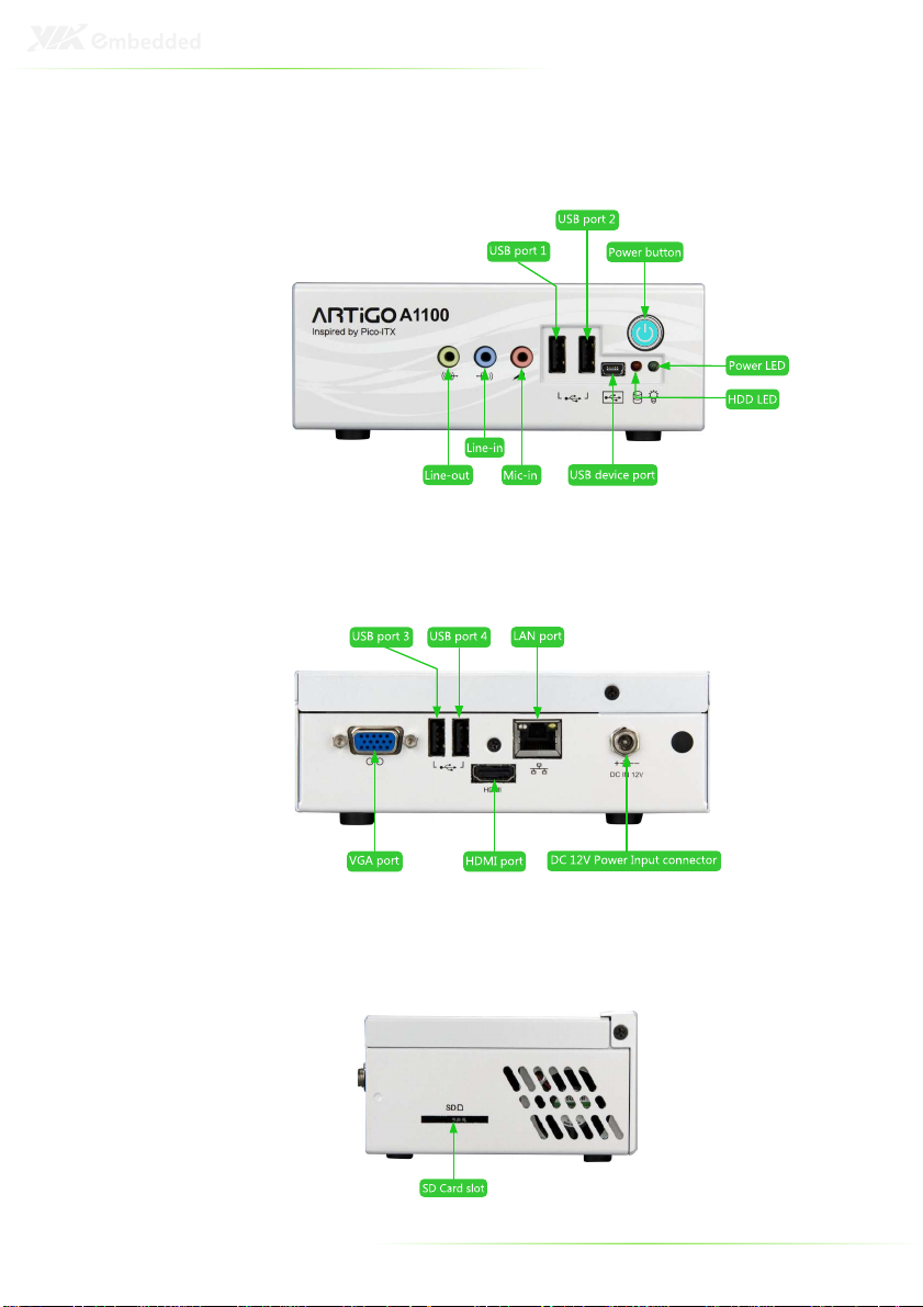
FRONT I/O LAYOUT
REAR I/O LAYOUT
SIDE I/O LAYOUT
10
Page 20
I/O PIN DESCRIPTION
Power Button
The ARTiGO-A1100 comes with a Power On/Off
button, that supports Soft Power-On/Off (Instant
Off or 4-Second Delay) and Suspend.
LED Indicators (Power LED and HDD LED)
There are two LEDs on the front face
plate that indicate the system status: The
Power LED indicates the power status
and flashes in green. The HDD LED
indicates the hard disk status and flashes
in red.
USB device port
The ARTiGO-A1100 provides a USB device port in the front panel for
quick data transfer to another computer.
Pin Signal
1 +5VUSBD
2 USBDP3 USBDP+
4 USBID
5 GND
USB 2.0 ports
The ARTiGO-A1100 provides four USB 2.0 ports (two in the front
panel, and two in the rear panel) for Plug & Play and hot
swapping access to external devices. The USB interface complies
with USB UHCI, Rev. 2.0.
Pin Signal
1 VCC
2 USB_P03 USB_P0+
4 GND
11
Page 21
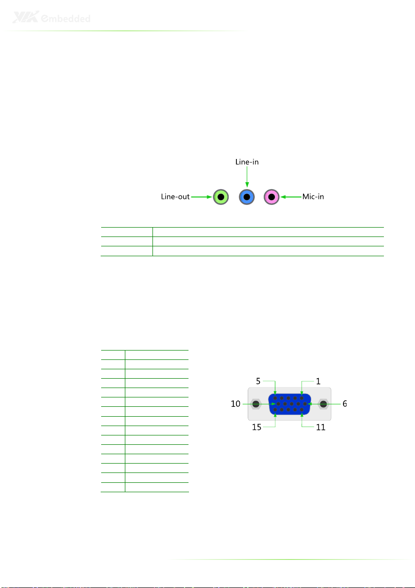
Audio Ports (Line-out, Line-in and Mic-in)
The ARTiGO-A1100 offers High Definition Audio through three
3.5 mm TRS jack connectors: Line-out, Line-in and Mic-in.
The Line-out jack is for connecting to external speakers or
headphones. The Line-In jack is for connecting to an external audio
device such as a CD player, tape player, etc. The Mic-in jack is for
connecting to a microphone.
Connector Type
Line-out Phone Jack 3.5Ø 5P, 90 Degree, Female, color lime green, SHIELDED
Line-in Phone Jack 3.5Ø 5P, 90 Degree, Female, color light blue, SHIELDED
Mic-in Phone Jack 3.5Ø 5P, 90 Degree, Female, color light pink, SHIELDED
VGA Port
The ARTiGO-A1100 provides a high resolution VGA interface
through a 15-pin D-sub female connector to support analog VGA
CRT monitors. It supports VGA and VESA, up to 1920 x 1200 @
60Hz resolution and up to 256 MB shared memory.
Pin Signal
1 Red
2 Green
3 Blue
4 NC
5 GND
6 GND
7 GND
8 GND
9 NC
10 GND
11 NC
12 DDC DAT
13 H-SYNC
14 V-SYNC
15 DDC CLK
12
Page 22
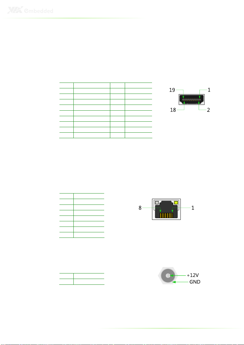
HDMI Port
The ARTiGO-A1100 provides a High Definition Multimedia
Interface (HDMI) port for connecting to high definition video and
digital audio. The HDMI port connector allows you to connect
digital video devices which utilize a high definition video signal.
Pin Signal Pin Signal
1 TX2+ 2 GND
3 TX2- 4 TX1+
5 GND 6 TX17 TX0+ 8 GND
9 TX0- 10 TXC+
11 GND 12 TXC13 - 14 15 DDCSCL 16 DDCSDA
17 GND 18 +5V
19 Hot Plug Detect
LAN Port
The ARTiGO-A1100 is equipped with the VIA VT6122 Gigabit LAN
controller. The Ethernet port provides a standard RJ-45 jack
connector with LED indicators to show its Active/Link status
(green LED) and Speed status (white LED).
Pin Signal
1 TXPA
2 TXNA
3 TXPB
4 TXNB
5 TXPC
6 TXNC
7 TXPD
8 TXND
Power Input (DC-In) Port
The ARTiGO-A1100 comes with a DC Power Input connector jack.
Pin Signal
1 GND
2 +12V
13
Page 23

14
Page 24

3
Basic installation
15
Page 25

INSTALLING THE MEMORY
Step 1
Step 1
Step 1Step 1
Locate the memory access cover on the bottom side of the
ARTiGO-A1100 and remove the screw.
Step 2
Step 2
Step 2Step 2
Remove the memory access cover as indicated in the figure below.
16
Page 26

Step 3
Step 3
Step 3Step 3
Insert the memory module into the SODIMM socket at the 45
degree angle. Then push down until the memory module snaps
into place. The SODIMM socket has two locking mechanisms that
will click once the memory module has been fully inserted.
Step 4
Step 4
Step 4Step 4
On the bottom side of the memory access cover, remove the
protective (plastic) layer of the memory thermal pad.
17
Page 27

Step
Step 5555
Step Step
Reinstall the memory access cover and secure it with screw.
18
Page 28

OPENING THE TOP COVER CHASSIS
Step 1
Step 1
Step 1Step 1
Remove the screw of the top cover from the rear panel of the
ARTiGO-A1100.
Step 2
Step 2
Step 2Step 2
Then gently slide the top cover backward and lift off the top cover
as indicated in the figure below.
19
Page 29

INSTALLING THE SATA 2.5” HARD DISK
Step 1
Step 1
Step 1Step 1
Gently slide and remove the top cover backward and lift off the
top cover.
Step
Step 2222
Step Step
On the bottom side of the top cover, remove the SATA 2.5” hard
disk cover plate by unscrewing the four screws.
20
Page 30

Step
Step 3333
Step Step
Attach the hard disk plate to the 2.5-inch SATA hard disk by
aligning the mounting holes on the SATA 2.5” hard disk with the
mounting holes on the hard disk cover plate. Then secure the
hard disk in place with four screws.
Step
Step 4444
Step Step
On the bottom side of the top cover, remove the protective
(plastic) layer of the hard disk thermal pad.
21
Page 31

Step
Step 5555
Step Step
Reinstall the hard disk plate by aligning the cover plate with the
mounting holes under the top cover and secure it with four
screws.
Step
Step 6666
Step Step
Connect the SATA power and SATA data cables to the hard disk.
22
Page 32

Step
Step 7777
Step Step
Replace the top cover onto the ARTiGO-A1100.
23
Page 33

INSTALLING THE SD CARD READER
Step 1
Step 1
Step 1Step 1
Locate the mounting area of SD card reader. Remove the five
screws in order to remove the front panel plate.
Step 2
Step 2
Step 2Step 2
Remove the fan duct as indicated in the figure below.
24
Page 34

Step 3
Step 3
Step 3Step 3
Mount the SD card reader module (EMIO-5130) and secure it with
two screws.
Step 4
Step 4
Step 4Step 4
Locate the SD card reader pin headers on the SD card reader
module (EMIO-5130) and on the P820-B daughter card.
25
Page 35

Step 5
Step 5
Step 5Step 5
Gently connect the SD card reader cable to the pin header on the
SD card reader module (EMIO-5130) and to the pin header on the
P820-B daughter card.
26
Page 36

Step
Step 6666
Step Step
Properly route the SD card reader cable underneath the fan duct.
Then reinstall the fan duct and front panel plate.
Step
Step 7777
Step Step
Replace the top cover of the ARTiGO-A1100.
27
Page 37

INSTALLING THE WLAN KIT
Step 1
Step 1
Step 1Step 1
Remove the top cover and the front panel plate by unscrewing
the five screws as indicated in the figure below.
Step 2
Step 2
Step 2Step 2
Remove the four screws indicated by the red arrows and carefully
lift the fan duct off the board.
28
Page 38

Step 3
Step 3
Step 3Step 3
Locate the WLAN pin header on the P820-B daughter card.
Step 4
Step 4
Step 4Step 4
Gently connect WLAN USB cable to the pin header on the P820-B
daughter card.
29
Page 39

Step 5
Step 5
Step 5Step 5
First reinstall the fan duct, and connect the grounding cable to one
of the screws of the fan duct as indicated in the figure below. Then
attach the front panel plate and secure it with screws.
Note:
Make sure the WLAN USB cable is properly routed underneath
the fan duct.
Step
Step 6666
Step Step
Locate the WLAN antenna hole at the rear side of the chassis and
install the WLAN antenna.
30
Page 40

Step
Step 7777
Step Step
Mount the WLAN USB module (EMIO-1530) on the bottom side
of chassis top cover with two screws.
Step
Step 8888
Step Step
Connect the WLAN USB cable to the mini connector on the WLAN
module and the grounding cable to the screw area. Then connect
the WLAN antenna cable to the micro RF connector on the WLAN
USB module (EMIO-1530) as indicated in the figure below.
Step
Step 9999
Step Step
Reinstall the top cover of the ARTiGO-A1100.
31
Page 41

INSTALLING VESA MOUNT BRACKET
An optional VESA mount bracket kit is available for mounting the
ARTiGO-A1100 behind the monitor.
Step
Step 1111
Step Step
Attach the VESA mount bracket to the back of the monitor as
indicated in the figure.
32
Page 42

Step
Step 2222
Step Step
Place the ARTiGO-A1100 unit into the VESA mount bracket. Then
connect all the necessary cables from the opening in the base of
the bracket.
33
Page 43

34
Page 44

4
BIOS Setup
This chapter gives a detailed explanation of the BIOS setup
functions.
35
Page 45

ENTERING THE BIOS SETUP MENU
Power on the computer and press <De
of the boot sequence to enter the BIOS setup menu. If you missed
the BIOS setup entry point, restart the system and try again.
Delete
lete> during the beginning
DeDe
letelete
CONTROL KEYS
Keys Description
Up Move to the previous item
Down Move to the next item
Left Move to the previous tab
Right Move to the next tab
Enter Select the item
Esc Jumps to the Exit menu or returns to the main menu
+ (number pad) Increase the numeric value
- (number pad) Decrease the numeric value
F1 General help, only for Status Page Setup Menu and
F7 Discard Changes
F9 Load Optimized defaults
F10 Save all the changes and exit
from a submenu
Option Page Setup Menu
36
Page 46

GETTING HELP
The BIOS setup program provides a “General Help
can display this screen from any menu/sub-menu by pressing
<F1
F1>. The help screen displays the keys for using and navigating
F1F1
the BIOS setup. Press <Esc
Esc> to exit the help screen.
EscEsc
General Help” screen. You
General HelpGeneral Help
37
Page 47

MAIN MENU
AMIBIOS
BIOS version number and related information.
Processor
CPU information.
System Memory
Memory size.
System Time
Use the key “+” or “-” to configure system time. The time format is
[Hour : Minute : Second].
System Date
Use the key “+” or “-” to configure system Date. The date format is
[Day, Month, Date, Year].
38
Page 48

ADVANCED SETTINGS
CPU Configuration
IDE Configuration
ACPI Configuration
APM Configuration
Spread Spectrum Configuration
USB Configuration
39
Page 49

CPU CONFIGURATION
CMPXCHG8B instruction support
Settings: [Enabled, Disabled]
Nano CPU Thermal Monitor Adjust
Settings: [Disabled, Thermal Monitor 1, Thermal Monitor 2,
Thermal Monitor 3]
40
Page 50

IDE CONFIGURATION
Parallel ATA IDE Controller
Settings: [Disabled, Primary]
Hard Disk Write Protect
Settings: [Disabled, Enabled]
IDE Detect Time Out (Sec)
Settings: [0, 5, 10, 15, 20, 25, 30, 35]
ATA(PI) 80Pin Cable Detection
Settings: [Host & Device, Host, Device]
41
Page 51

IDE DRIVES
Primary IDE Master
Primary IDE Slave (SATA Device)
42
Page 52

Type
Settings: [Not Installed, Auto, CD/DVD, ARMD]
LBA/Large Mode
Settings: [Disabled, Auto]
Block (Multi-Sector Transfer)
Settings: [Disabled, Auto]
PIO Mode
Settings: [Auto, 0, 1, 2, 3, 4]
DMA Mode
Settings: [Auto]
S.M.A.R.T.
Self Monitoring Analysis and Reporting Technology, a monitoring
system for hard disks.
Settings: [Auto, Disabled, Enabled]
32Bit Data Transfer
Settings: [Enabled, Disabled]
43
Page 53

ACPI SETTINGS
General ACPI Configuration
This menu contains ACPI (Advanced Configuration and Power
Management Interface) options.
Advanced ACPI Configuration
Chipset ACPI Configuration
44
Page 54

GENERAL ACPI CONFIGURATION
Suspend Mode
Select the ACPI state used for system suspend.
Settings Description
S1(POS) S1/Power On Suspend (POS) is a low power state. In this
state, no system context (CPU or chipset) is lost and
hardware maintains all system contexts
S3(STR) S3/Suspend To RAM (STR) is a power-down state. In this
state, power is supplied only to essential components
such as main memory and wakeup-capable devices. The
system context is saved to main memory, and context is
restored from the memory when a "wakeup" event
occurs.
Auto Depends on the OS to select the state.
Repost Video on S3 Resume
To determine whether to invoke VGA BIOS post on S3/STR
resume or not.
Settings: [No, Yes]
45
Page 55

ADVANCED ACPI CONFIGURATION
ACPI Version Features
To enable RSDP pointers to 64-bit Fixed System Description Tables.
Settings: [ACPI v1.0, ACPI v2.0, ACPI v3.0]
ACPI APIC Support
To include ACPI APIC table pointer to RSDT pointer list.
Settings: [Enabled, Disabled]
AMI OEMB Table
To include OEMB table pointer to R(X)SDT pointer lists.
Settings: [Disabled, Enabled]
Headless Mode
To enable or disable headless operation mode through ACPI.
Settings: [Disabled, Enabled]
46
Page 56

CHIPSET ACPI CONFIGURATION
USB Device Wakeup Function
Settings: [Disabled, Enabled]
47
Page 57

APM CONFIGURATION
Power Management / APM
Settings: [Disabled, Enabled]
Power Button Mode
Settings: [On/Off, Standby, Suspend]
Suspend Power Saving Type
Settings: [C3, S1]
Restore on AC / Power Loss
The field defines how the system will respond after an AC power
loss during system operation.
Settings Description
Power Off Keeps the system in an off state until the power button is
Power On Restarts the system when the power is back
Last State Save in last state
pressed.
Manual Throttle Ratio
Settings: [0%-6.25%, 6.25%-12.5%, 18.75%-25%, 31.25%-37.5%,
37.5%-43.75%, 43.75%-50%, 50%-56.25%, 56.25%-62.5%, 62.5%-
68.75%, 68.75%-75%, 75%-87.5%, 75%-81.25%, 81.25%-87.5%,
87.5%-93.75%, 93.75%-100%]
48
Page 58

System Thermal
Settings: [Disabled, Enabled]
Standby Time Out
Settings: [Disabled, 1/2/4/8/10/20/30/40/50/60 minutes]
Suspend Time Out
Settings: [Disabled, 1/2/4/8/10/20/30/40/50/60 minutes]
Hard Disk Time Out (Minute)
Settings: [Disabled, 1/2/3/4/5/6/7/8/9/10/11/12/13/14/15
minutes]
Green PC Monitor Power State
Settings: [Standby, Suspend, Off]
Video Power Down Mode
Settings: [Disabled, Standby, Suspend]
Hard Disk Power Down Mode
Settings: [Disabled, Standby, Suspend]
Display Activity
Settings: [Ignore, Monitor]
Monitor IRQ3~15
Enables or disables the monitoring of the specified IRQ line.
Settings: [Ignore, Monitor]
Note:
IRQ (Interrupt Request) lines are system resources allocated to
I/O devices. When an I/O device needs to gain attention of the
operating system, it signals this by causing an IRQ to occur.
After receiving the signal, when the operating system is ready,
the system will interrupt itself and perform the service required
by the IO device.
49
Page 59

Resume on Ring
Settings: [Disabled, Enabled]
Resume on PME#
Settings: [Disabled, Enabled]
Resume On PS/2 KBC
Settings: [Disabled, S3, S3/S4/S5]
Wake-up Key
Settings: [Any Key, Specific Key]
Resume on PS/2 Mouse
Enable any mouse activity to restore the system from the power
saving mode to an active state.
Settings: [Disabled, S3, S3/S4/S5]
Resume on RTC Alarm
Set a scheduled time and/or date to automatically power on the
system.
Settings: [Disabled, Enabled]
50
Page 60

SPREAD SPECTRUM CONFIGURATION
Spread Spectrum Configuration
Settings: [Disabled, 0.1%, 0.2%, 0.3%, 0.4%, 0.5%, 0.6%, 0.7%, 0.8%,
0.9%]
51
Page 61

USB CONFIGURATION
USB 1.1 Ports Configuration
To enable USB 1.1 host controllers.
Settings: [Disabled, USB 2 ports, USB 4 ports, USB 6 ports]
USB 2.0 Ports Enable
To enable USB 2.0 host controllers.
Settings: [Disabled, Enabled]
USB Device Mode Enable
Settings: [Enabled, Disabled]
Legacy USB Support
To enable support for legacy USB.
Settings: [Disabled, Enabled, Auto]
USB 2.0 Controller Mode
To configure the USB 2.0 controller in HiSpeed (480Mbps) or
FullSpeed (12Mbps).
Settings: [FullSpeed, HiSpeed]
BIOS EHCI Hand-Off
Settings: [Disabled, Enabled]
52
Page 62

ADVANCED PCI/PNP SETTINGS
Note:
This section covers some very technical items and it is strongly
recommended to leave the default settings as it is unless you
are an experienced user.
Clear NVRAM
To clear NVRAM during system boot.
Settings: [No, Yes]
Plug & Play O/S
Settings: [No, Yes]
PCI Latency Timer
Value in units of PCI clocks for PCI device latency timer register.
Settings: [32, 64, 96, 128, 160, 192, 224, 248]
Allocate IRQ to PCI VGA
Settings: [Yes, No]
Palette Snooping
Settings: [Disabled, Enabled]
53
Page 63

PCI IDE BusMaster
Settings: [Disabled, Enabled]
Off Board PCI/ISA IDE Card
Settings: [Auto, PCI Slot1, PCI Slot2, PCI Slot3, PCI Slot4, PCI Slot5,
PCI Slot6]
IRQ3~15
Settings: [Available, Reserved]
DMA Channel 0~7
Settings: [Available, Reserved]
Reserved Memory Size
To decide the size of memory block to reserve for legacy ISA
devices.
Settings: [Disabled, 16k, 32k, 64k]
54
Page 64

BOOT SETTINGS
Boot Settings Configuration
Configuration settings during system boot.
Boot Device Priority
Specifies the boot device priority sequence.
55
Page 65

BOOT SETTINGS CONFIGURATION
Quick Boot
Settings: [Disabled, Enabled]
Display Logo
Settings: [Disabled, Enabled]
AddOn ROM Display Mode
Settings: [Force BIOS, Keep Current]
Bootup Num-Lock
To select power-on state for Num-Lock.
Settings: [Off, On]
PS/2 Mouse Support
Settings: [Disabled, Enabled, Auto]
Wait For ‘F1’ If Error
Settings: [Disabled, Enabled]
Hit ‘DEL’ Message Display
Settings: [Disabled, Enabled]
56
Page 66

Interrupt 19 Capture
Settings: [Disabled, Enabled]
57
Page 67

BOOT DEVICE PRIORITY
1st Boot Device
To specifies the boot sequence from the available devices. The
available boot devices are detected dynamically according to real
situation and variable options will be provided.
Settings: [Network: VIA Networking Bootagent, Disabled]
58
Page 68

SECURITY SETTINGS
Change Supervisor Password
This option is for setting a password for entering BIOS Setup.
When a password has been set, a password prompt will be
displayed whenever BIOS Setup is run. This prevents an
unauthorized person from changing any part of your system
configuration.
When a supervisor password is used, the BIOS Setup program can
be accessed and the BIOS settings can be changed.
Change User Password
When a user password is used, the BIOS Setup program can be
accessed but the BIOS settings cannot be changed.
Boot Sector Virus Protection
Settings: [Disabled, Enabled]
59
Page 69

ADVANCED CHIPSET SETTINGS
Caution:
The Advanced Chipset Features menu is used for optimizing the
chipset functions. Do not change these settings unless you are
familiar with the chipset.
North Bridge VIA VX855 Configuration
South Bridge VIA VX855 Configuration
60
Page 70

NORTH BRIDGE VIA VX855
CONFIGURATION
Software Reset E2 Issue
Settings: [Patch, Escape Patch]
Change DCLK using RDCKM
Settings: [Program, Escape Program]
Dynamic CKE
Settings: [Disabled, Enabled]
NB Performance Register
Settings: [Disabled, Enabled]
NB Energy Saving Register
Settings: [Disabled, Enabled]
61
Page 71

ONCHIP VGA CONFIGURATION
VGA Frame Buffer Size
Settings: [64MB, 128MB, 256MB]
CPU Direct Access Frame Buffer
Settings: [Disabled, Enabled]
Select Display Device
Settings: [CRT, LCD, HDMI, CRT+LCD, CRT+HDMI]
Panel Type
Settings: [02]
Dithering
Settings: [Disabled, Enabled]
Backlight Control
Settings: [0%, 25%, 50%, 75%, 100%]
62
Page 72

SOUTH BRIDGE VIA VX855
CONFIGURATION
Parallel Channel Enable
Settings: [Enabled, Disabled]
ISA Master Support
Settings: [Support, Not Support]
High Definition Audio
Settings: [Disabled, Auto]
Enable Embedded COM
Settings: [Disabled, Enabled]
PCI Debug Master Mode
Settings: [Disabled, Enabled]
SMBus Multi-Master
Settings: [Disabled, Enabled]
PCI VCC33 Leakage Patch
Settings: [Disabled, Enabled]
63
Page 73

PCI Delay Transaction
Settings: [Disabled, Enabled]
WATCH-DOG
Settings: [Disabled, Enabled]
64
Page 74

EXIT OPTIONS
Save Changes and Exit
Exit system setup after saving the changes, or press “F10”.
Discard Changes and Exit
Exit system setup without saving any changes, or press “Esc”.
Discard Changes
Discard changes which have been done so far to any of the setup
questions, or press “F7”.
Load Optimal Defaults
Load optimal default values for all the setup items, or press “F9”.
The default optimized values are set by the mainboard
manufacturer to provide a stable system with optimized
performance.
65
Page 75

66
Page 76

5
Driver Installation
This chapter gives you brief descriptions of each mainboard driver
and application. You must install the VIA chipset drivers first before
installing other drivers such as VGA drivers. The applications will
only function correctly if the necessary drivers are already installed.
67
Page 77

DRIVER UTILITIES
Getting Started
The ARTiGO-A1100 includes a driver CD that contains the drivers
and software for enhancing the performance of the system. The
drivers can also be downloaded from http://www.via.com.tw.
Note:
The driver utilities and software are updated from time to time.
The latest updated versions are available at
http://www.via.com.tw
Running the Driver Utilities CD
To start using the CD, insert the CD into the CD-ROM or DVDROM drive. The CD should run automatically after closing the CDROM or DVD-ROM drive. The driver utilities and software menu
screen should then appear on the screen. If the CD does not run
automatically, click on the “Start” button and select “Run…” Then
type: "D:\Setup.exe".
For Linux drivers, click the right button on mouse and click open.
Linux drivers are located in the "Driver" folder.
Note:
D: might not be the drive letter of the CD-ROM/DVD-ROM in
your system.
68
Page 78

CD CONTENT
VIA 4 in 1 Drivers
VIA 4 in 1 Drivers
VIA 4 in 1 DriversVIA 4 in 1 Drivers
Contains VIA ATAPI Vendor Support Driver (enables the
performance enhancing bus mastering functions on ATAcapable Hard Disk Drives and ensures IDE device
compatibility), AGP VxD Driver (provides service routines
to your VGA driver and interface directly to hardware,
providing fast graphical access), IRQ Routing Miniport
Driver (sets the system's PCI IRQ routing sequence) and
VIA INF Driver (enables the VIA Power Management
function).
Includes V-RAID and RAID tools.
VIA Graphics Driver
VIA Graphics Driver
VIA Graphics DriverVIA Graphics Driver
Enhances the onboard VIA graphic chip.
Windows XP and Linux drivers are provided.
VIA Audio Driver
VIA Audio Driver
VIA Audio DriverVIA Audio Driver
Enables access to the onboard VIA HD audio codec.
VIA USB 2.0 Driver
VIA USB 2.0 Driver
VIA USB 2.0 DriverVIA USB 2.0 Driver
Enhances VIA USB 2.0 ports.
VIA LAN Driver
VIA LAN Driver
VIA LAN DriverVIA LAN Driver
Enhances the onboard VIA VT6122 Gigabit Ethernet
Chipset.
VIA Transmit SW Package
VIA Transmit SW Package
VIA Transmit SW PackageVIA Transmit SW Package
Enhances VIA USB Device function and software package
of date transmit function.
69
 Loading...