

Page 1
AMOS-5210
Quick Guide
Key Features:
•
Fanless operation
•
Quick installation and easy maintenance
•
Modularized design with compact
dimension
•
Easy to use, interchangeable and
customizable front and rear panels
•
Built-in common I/O functional cutouts
for an easy external access
P/N: 99G51-013024-10
The VIA AMOS-5210 is a rugged chassis kit, specially designed for VIA
EITX-3000 Em-ITX board stacked with EMIO-3210 Em-IO module. The
chassis kit offers fast and easy assembly. It consists of three parts: front
and rear I/O access plates, and the top cover.
The modularity of AMOS-5210 chassis kit combines with heatsink found
on EMIO-3210 board forming a solid and robust system chassis . And it
gives the developers a wealth of advantages including rich and versatile
I/O configurations through its expansive dual I/O coastline.
A system with the combination of AMOS-5210 chassis kit, EITX-3000
board and EMIO-3210 module can supports up to ten serial ports
(eight RS-232/422/485 ports are configurable in BIOS setup) and two
parallel ports. The combination is ideally suited for Kiosk and industrial
automation embedded applications.
Specifications:
• Chassis Construction:
▪ Front and rear I/O metal face plate
▪ Top cover metal plate
▪ Aluminum bottom chassis housing mixed
copper heat-pipe (installed with EITX-3000
board)
• Front I/O support:
▪ 2 x 3.5Φ Audio jacks (default audio cable)
− Line-out and Mic-in
▪ 7 x Serial ports (COM ports)
− D-Sub 9-pin COM connector
− COM1 ~ COM4 (two RS-232 and two
RS-232/422/485) from EITX-3000
− COM 5 ~ COM 7 (three RS-232/422/485)
from EMIO-3210
▪ 1 x GPIO port (default GPIO cable connector)
− D-sub 9-pin GPIO male connector
▪ 2 x USB ports (onboard USB connector)
− USB 2.0 compliant
▪ 1 x DC-in port (onboard power input)
− 2-pole Phoenix power input
▪ 1 x ATX Power On/Off button
▪ 1 x Green LED indicator (Power On/Off status)
▪ 1 x Red LED indicator (HDD activities status)
• Rear I/O support:
▪ 1 x VGA connector
− D-sub 15-pin VGA connector
▪ 2 x LVDS connectors
− DB-26 connectors as LVDS1 and LVDS2
▪ 2 x GigaLAN connectors
− RJ-45 connectors
− GigaLAN connectors as LAN1 and LAN2
▪ 2 x Parallel ports
− D-Sub 25-pin parallel ports (LPT1 and LPT2)
▪ 3 x Serial ports (COM ports)
− D-Sub 9-pin COM connector
− COM8 ~ COM10 (three RS-232/422/485)
from EMIO-3210
• Board-level support:
▪ Compatible with VIA EITX-3000 embedded
board and EMIO-3210 module
• Drive bay:
▪ Default support 1 x 2.5” hard disk drive bay
located on the aluminum bottom housing
(from EMIO-3210)
▪ Default support 1 x CompactFlash (CF) socket
(from EITX-3000)
• Mounting (optional):
▪ Supports table mounting and wall mounting
• Dimension after assembly:
▪ 330.6 mm (W) x 54.2 mm (H) x 124.8 mm (D)
• Weight (front, rear and top cover plates):
▪ 0.7 kg
• Barebones weight (after assembly):
▪ 2.4 kg (plates and aluminum bottom housing)
• Operating Temperature:
▪ 0˚C up to 45˚C (system equipped HDD)
▪ -20˚C up to 55˚C (system equipped CF card)
• Storage Temperature:
▪ -20˚C up to 60˚C
• Relative Humidity:
▪ 0 % to 90 % @ 45˚C, non-condensing
• EMC approved:
▪ CE, FCC, CCC Class A
• Safety approved:
▪ CB, CCC
Packing List:
• 1 x Front I/O plate (P/N: 99G42-091676-A1)
• 1 x Rear I/O plate (P/N: 99G42-091686-A1)
• 1 x Top cover plate (P/N: 99G42-091666-A1)
• 2 x Hex spacer kit (P/N: 99G44-030221)
• 1 x Screw pack (P/N: 99G44-030231)
− 23 x M*3.5 mm screws
• 1 x GPIO cable (P/N: 99G33-080185)
• 1 x Audio jacks cable (P/N: 99G33-09039A)
• 1 x CF cover (P/N: 99G42-090886-A0)
• 1 x SATA (data and power) cable (P/N: 99G33-02093F)
• 1 x Antenna cover (P/N: 99G43-120011)
• 1 x Quick guide (P/N: 99G51-013024-10)
Note:
Please ensure that all items in the packing list are present
before using this product. If any of the items are missing or
damaged, contact your distributor or sales representative
immediately.
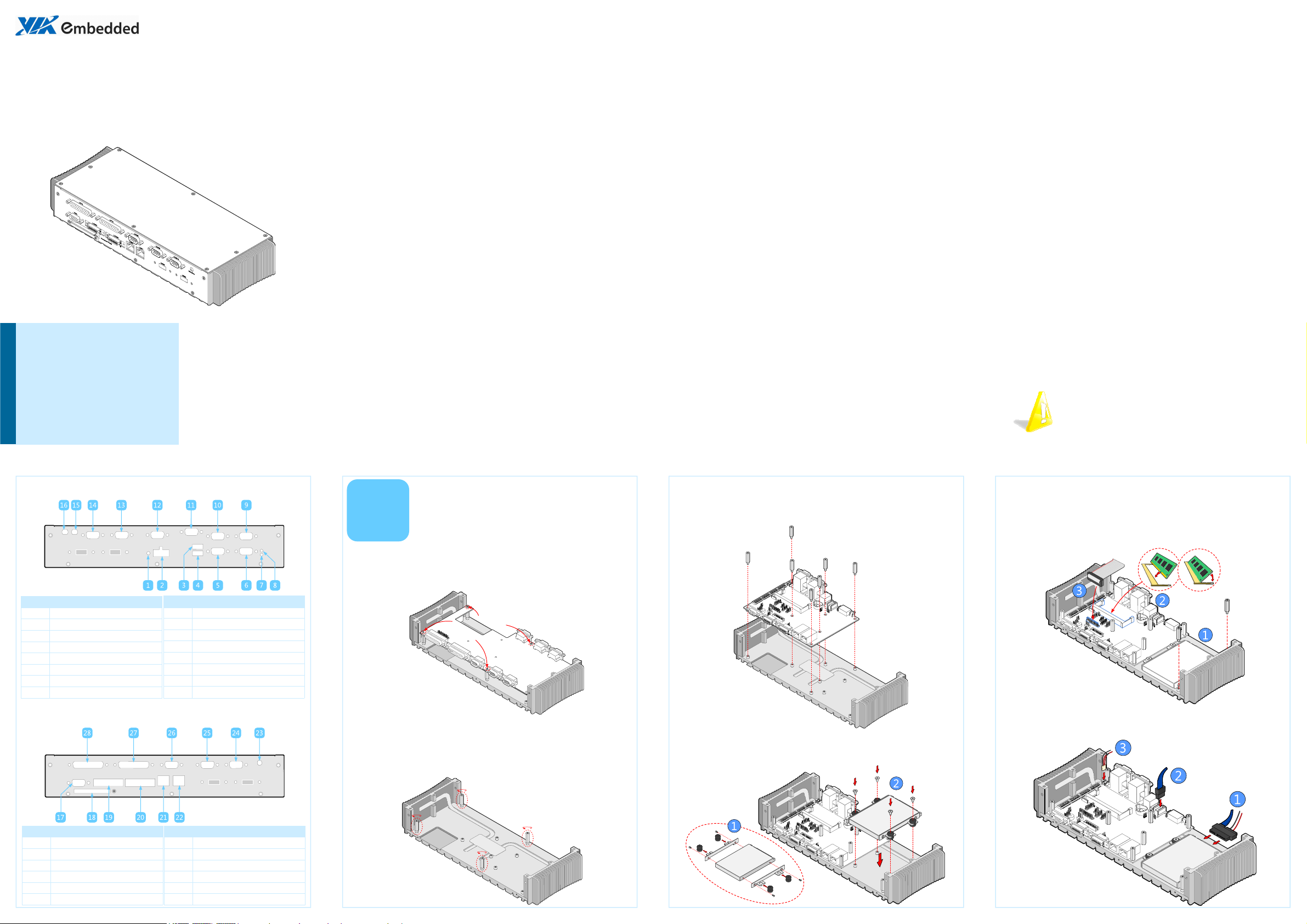
Front I/O cutout layout
Item Description
1 Power button (Power On/Off)
2 DC-in power input connector
3 USB 2.0 port 1 (USB1)
4 USB 2.0 port 2 (USB2)
5 COM2 port (RS-232/422/485)
6 COM1 port (RS-232/422/485)
7 Power LED indicator
8 HDD LED indicator
Item Description
Rear I/O cutout layout
9 COM3 port (RS-232)
10 COM4 port (RS-232)
11 GPIO port
12 COM5 port (RS-232/422/485)
13 COM6 port (RS-232/422/485)
14 COM7 port (RS-232/422/485)
15 Mic-in jack
16 Line-out jack
Installing EITX-3000,
1
Step 1
Remove the four screws indicated by the red arrows and carefully lift
the EMIO-3210 module off the heatsink.
Step 2
Remove the four spacers indicated by the red ovals. Turn the spacers in
the counterclockwise direction to loosen.
2.5” HDD & Memory
Step 3
Align the EITX-3000 board over the mounting holes and secure it to
the heatsink using the seven medium length spacers.
Step 4
After the hard disk brackets have been attached to the hard disk,
mount the brackets to the heatsink. Secure the brackets in place with
the four bracket screws.
Step 5
Install the long spacers. After that, insert the memory module into the
SODIMM socket at the 45 degrees angle and push down until the
memory module snaps into place. Then attach one end of the LPT
cable to LPT pinhead connector on the EITX-3000 board.
Step 6
Connect the SATA (power and data) cables to the hard disk and onto
the EITX-3000 board connector.
Item Description
17 VGA port
18 CompactFlash slot
19 LVDS port 1 (LVDS1)
20 LVDS port 2 (LVDS2)
21 RJ-45 GigaLAN port 2 (LAN2)
22 RJ-45 GigaLAN port 1 (LAN1)
Item Description
23 WLAN antenna hole
24 COM10 (RS-232/422/485)
25 COM9 (RS-232/422/485)
26 COM8 (RS-232/422/485)
27 LPT port 2 (LPT2)
28 LPT port 1 (LPT1)
Page 2
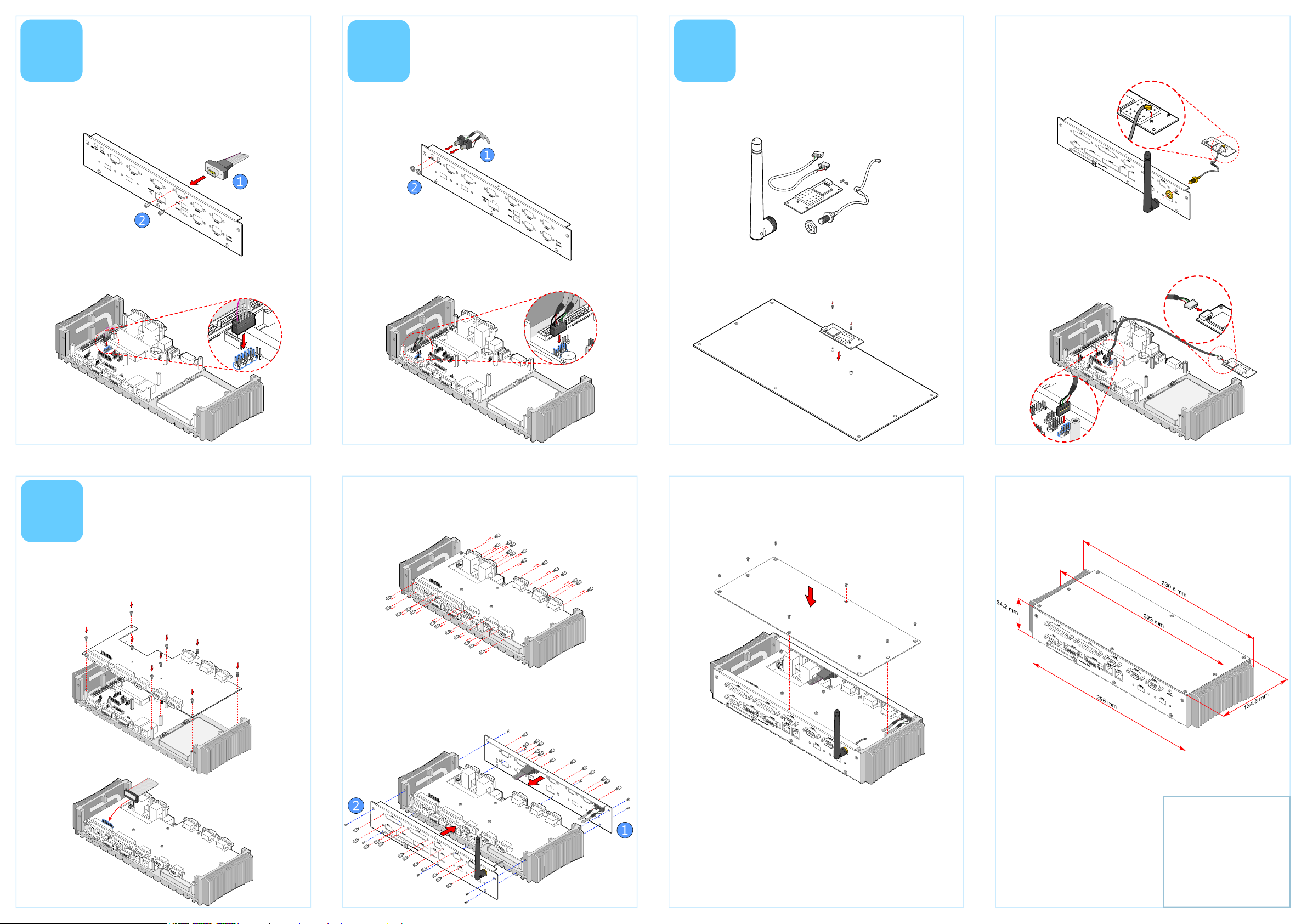
2
Installing the
GPIO connector
3
Installing the
audio jack cable
4
Installing the WiFi
module (optional)
Step 2
Insert the WLAN port (with washer) into the antenna cutout and
fasten it with the nut. Then install the external antenna and connect
the mini coaxial cable to the mini RF connector onto WLAN module.
Step 1
Insert the D-sub 9-pin GPIO connector into the GPIO cutout and
fasten the provided standoff screws to secure the connector.
Step 2
Locate the GPIO pin header on the EITX-3000 board and gently
connect the other end of GPIO cable to the pin header.
Step 1
Insert the two audio jacks into the audio cutout. Then fasten the
audio jacks in place with the nuts respectively.
Step 2
Locate the audio pin header on the EITX-3000 board and gently
connect the other end of audio jack cable to the pin header.
The WiFi kit should include the WiFi module, two screws, one boardto-board cable, one mini coaxial cable, one washer, one nut, and one
external antenna. The optional WLAN module includes a VT6656
WLAN controller and provides support for 802.11 b/g standards.
Step 1
Flip the top cover and align the WLAN module over the WLAN
mounting holes.
Step 3
Gently connect the WLAN board-to-board cable to the USB pin
header on the EITX-3000 board and to the mini connector on the
WLAN module.
Installing front , rear
5
Step 1
Align the EMIO-3210 module with the spacers, and secure the module
to the spacers with the nine mounting screws. (M3*6mm). Then
connect the other end of LPT cable to pinhead connector.
and top plate
Step 2
Remove all standoff screws from the front and rear I/O connectors of
the EMIO-3210 module.
Step 3
Align the front and rear I/O plates to the heatsink of the EITX-3000
board stacked with EMIO-3210 module. And reinstall all the standoff
screws (P/N: 99G44-030221) to the front and rear connectors.
Step 4
Align the top cover over the mounting holes on the heatsink. Then
secure the top cover with eight mounting screws.
Dimensions
For more information on this and
other VIA products, please visit
www.viaembedded.com.
For further support and service,
please visit www.via.com/tw/en/
products/mainboards/contact.jsp
VIA Technologies, Inc.
1F, 531, Zhong-Zheng Road,
Xindian, Taipei 23148
Taiwan
Tel: 886-2-2218-5452
Fax: 886-2-2218-5453
Web: www.via.com.tw
Copyright © 2010 VIA Technologies, Inc. All rights reserved.
 Loading...