

Page 1
AMOS-5110
Quick Guide
Key Features:
•
Fanless, and robust casting construction
•
High and scalable performance with low
power consumption
•
Quick installation and easy maintenance
•
Easy to use, interchangeable and
customizable front and rear panels
•
Built-in common I/O functional cutouts
for an easy external access
P/N: 99G51-013014-10
The VIA AMOS-5110 is a rugged chassis kit, specially designed for VIA
EITX-3000 Em-ITX board stacked with EMIO-3110 Em-IO module. The
chassis kit offers fast and easy assembly. It consists of four parts: front
and rear I/O access plates, storage bottom chassis and the top cover.
The modularity of AMOS-5110 chassis kit combines with heatsink found
on the EITX-3000 board forming a solid and robust system chassis . It
gives developers a wealth of advantages including rich and versatile I/O
configurations through its expansive dual I/O coastline.
A system with the combination of AMOS-5110 chassis kit, EITX-3000
board and EMIO-3110 module can support up to six displays (four of
which can display completely different content). The combination is
ideally suited for display streaming media/advertisement in schools,
hospitals, corporations, airports, museums, retailers and train stations.
Specifications:
• Chassis Construction:
▪ Front and rear I/O metal face plate
▪ Top cover metal plate
▪ Storage sub-system metal chassis
▪ Aluminum bottom chassis housing mixed
copper heat-pipe (installed with EITX-3000)
• Front I/O support:
▪ 4 x Serial ports (COM ports)
− D-Sub 9-pin COM connector
− COM1 ~ COM4 (two RS-232 and two
RS-232/422/485) from EITX-3000
▪ 1 x GPIO port (default GPIO cable connector)
− D-sub 9-pin GPIO male connector
▪ 2 x USB ports (USB 2.0 compliant)
▪ 1 x VGA connector
− D-sub 15-pin connector (from EMIO-3110)
▪ 1 x DC-in port (onboard power input)
− 2-pole Phoenix power input
▪ 1 x ATX Power On/Off button
▪ 1 x WLAN antenna hole
▪ 1 x Green LED indicator (Power On/Off status)
▪ 1 x Red LED indicator (HDD activities status)
• Rear I/O support:
▪ 1 x VGA connector
− D-sub 15-pin connector
▪ 2 x LVDS connectors
− DB-26 connectors as LVDS1 and LVDS2
▪ 2 x GigaLAN connectors
− RJ-45 connectors
− GigaLAN connectors as LAN1 and LAN2
▪ 2 x 3.5Φ Audio jacks
− Speaker-out and Mic-in
▪ 2 x HDMI ports
− HDMI1 and HDMI2 (from EMIO-3110)
▪ 2 x DVI ports (as DVI1 and DVI2)
• Board-level support:
▪ Compatible with VIA EITX-3000 embedded
board and EMIO-3110 module
• Drive bay:
▪ Default support 1 x 2.5” SATA hard disk drive
bay located on the storage bottom chassis
▪ Default support 1 x CompactFlash
type I/II socket (from EITX-3000)
• Mounting (optional):
▪ Supports VESA, table and wall mounting
• Dimension after assembly:
▪ 232.6 mm (W) x 73 mm (H) x 124.8 mm (D)
• Weight (front & rear plates and storage chassis):
▪ 0.8 kg
• Barebones weight (after assembly):
▪ 2.0 kg (front & rear plates, storage chassis and
aluminum bottom housing)
• Storage Temperature: -20˚C up to 60˚C
• Operating Temperature:
▪ 0˚C up to 45˚C (system equipped with HDD)
▪ -20˚C up to 45˚C (system equipped with CF)
• Relative Humidity:
0% to 90% @ 45˚C, non-condensing
• EMC approved: CE, FCC, CCC Class A
• Safety approved: CB, CCC
Packing List:
• 1 x Front I/O plate (P/N: 99G42-091636-A1)
• 1 x Rear I/O plate (P/N: 99G42-091646-A1)
• 1 x Storage metal top cover (P/N: 99G42-091656-A1)
• 1 x Storage bottom case (P/N: 99G42-092076-A1)
• 1 x CompactFlash cover (P/N: 99G42-090886-A0)
• 1 x Antenna cover (P/N: 99G43-120011)
• 1 x GPIO cable kit (P/N: 99G33-080185)
- 1 x GPIO cable port
- 2 x 6mm hex standoff screw
• 1 x SATA HDD (data and power) cable (P/N: 99G33-02093F)
• 1 x Screw pack (P/N: 99G44-030231)
- 23 x M3*5mm screw
• 1 x Screw pack (P/N: 99G44-010415)
- 10 x M3*6mm screw
• 1 x Hex screw package (P/N: 99G44-030221)
- 16 x 6mm hex standoff screw
• 1 x Quick guide (P/N: 99G51-013014-10)
Note:
Please ensure that all items in the packing list are present
before using this product. If any of the items are missing or
damaged, contact your distributor or sales representative
immediately.
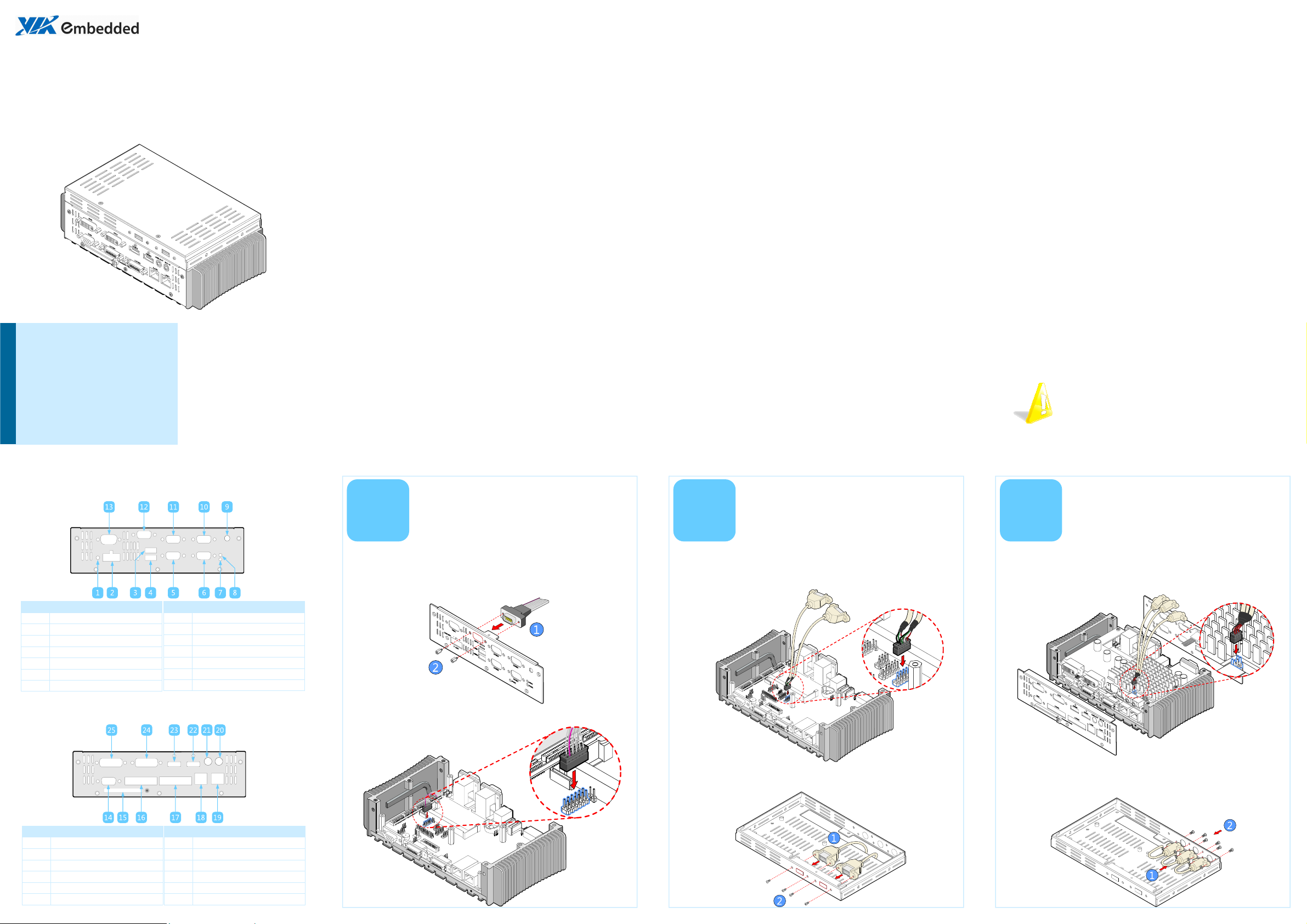
Front I/O cutout layout
Item Description
1 Power button (Power On/Off)
2 DC-in power input connector
3 USB 2.0 port 1 (USB1)
4 USB 2.0 port 2 (USB2)
5 COM2 port (RS-232/422/485)
6 COM1 port (RS-232/422/485)
7 Power LED indicator
Item Description
Rear I/O cutout layout
8 HDD LED indicator
9 WLAN antenna hole
10 COM3 port (RS-232)
11 COM4 port (RS-232)
12 GPIO port
13 VGA port
Installing the
1
Step 1
Break off the GPIO cutout filler. Then insert the D-sub 9-pin GPIO
connector into the GPIO cutout and fasten the provided hex standoff
screws to secure the connector.
Step 2
Locate the GPIO pinheader on the EITX-3000 mainboard and gently
connect the other end of GPIO cable.
GPIO cable
Installing the
2
Step 1
Locate the USB pinheader (USB_4/5) on the EITX-3000 board and
gently attach USB cable to the pinheader.
Step 2
Break off the USB cutout filler. Then attach USB cable port onto the
USB pre-cutout and fasten the screws to secure the USB cable port.
USB cable (optional)
Installing the TV-out
3
Step 1
Locate the TV-out pinheader (TV1) on the EMIO-3110 module and
gently attach Component video (YPbPr) cables to the pinheader.
Step 2
Break off the TV-out cutout filler. Then attach the other end (RCA
plugs) of the Component video (YPbPr) cables onto the TV precutout. And fasten the screws and nuts to secure the cables.
cables (optional)
Item Description
14 VGA port
15 CompactFlash slot
16 LVDS port 1 (LVDS1)
17 LVDS port 2 (LVDS2)
18 RJ-45 GigaLAN port 2 (LAN2)
19 RJ-45 GigaLAN port 1 (LAN1)
Item Description
20 Mic-in jack
21 Speaker-out jack
22 HDMI port 1 (HDMI1)
23 HDMI port 2 (HDMI2)
24 DVI port 1 (DVI2)
25 DVI port 2 (DVI1)
Page 2
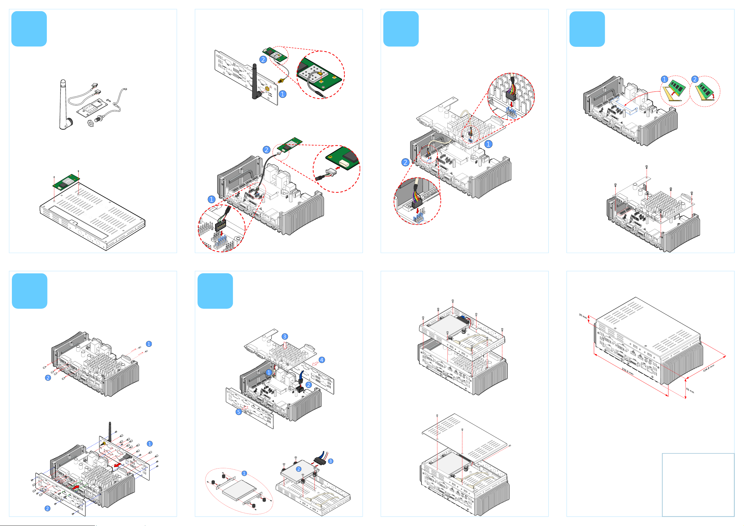
Installing WiFi (WLAN)
4
The WiFi kit should include the WiFi module, two screws, one boardto-board cable, one mini coaxial cable, one washer, one nut, and one
external antenna. The optional WLAN module includes a VT6656
WLAN controller and provides support for 802.11 b/g standards.
Step 1
Flip the storage chassis (bottom case) over and align the WLAN
module over the WLAN mounting holes. Then secure it with two
mounting screws.
module (optional)
Step 2
Insert the WLAN port (with washer) into the antenna cutout and
fasten it with the nut. Then install the external antenna, and connect
the mini coaxial cable to the mini RF connector onto WLAN module.
Step 3
Gently attach the WLAN board-to-board cable to the WLAN
pinheader (USB_2/3) on the EITX-3000 board and to the mini
connector on the WLAN module.
Installing board-to-
5
Step 1
Locate the audio pin header (JAUDIO1) on the EMIO-3110 module
and gently attach the board-to-board audio cable.
board audio cable
Installing SODIMM
6
Step 1
Insert the memory module into the SODIMM socket at 45 degrees
angle. Then push down the memory module until its snaps into place.
Step 2
Align the Em-IO connector on the bottom side of EMIO-3110 with the
Em-IO connector on the EITX-3000. Connect the module to the board
and secure it with six screws.
and EMIO-3110
Installing the front
7
Step 1
Remove all hex standoff screws from the front & rear I/O connectors
of EMIO-3110 module.
Step 2
Align the front and rear I/O plates to the heatsink. And install the
plates screws (P/N: 99G44-030231), HDMI screws (P/N: 99G44-
010415) and hex standoff screws (P/N: 99G44-030221) to the front
and rear connectors.
and rear I/O plates
Installing hard disk
8
Step 1
Connect the SATA (data and power) cable onto the EITX-3000 board.
Step 2
Mount the hard disk brackets on the 2.5” HDD. Then install the
brackets over the HDD mounting holes on the inside of the storage
chassis and secure it with four screws. And connect the other end of
SATA (data and power) cable to the hard disk.
and storage chassis
Step 2
Attach the other end of the board-to-board audio cable to the
pinheader (F_AUDIO) on the EITX-3000 board.
Step 3
Install and secure the bottom case of the storage chassis to the
heatsink with eight mounting screws (P/N: 99G44-010415).
Step 4
Align the top cover of the storage chassis with the bottom case of the
storage chassis. Then secure it with three screws (P/N: 99G44-030231).
Dimensions
For more information on this and
other VIA products, please visit
www.viaembedded.com.
For further support and service,
please visit www.via.com/tw/en/
products/mainboards/contact.jsp
VIA Technologies, Inc.
1F, 531, Zhong-Zheng Road,
Xindian, Taipei 23148
Taiwan
Tel: 886-2-2218-5452
Fax: 886-2-2218-5453
Web: www.via.com.tw
Copyright © 2010 VIA Technologies, Inc. All rights reserved.
 Loading...