

Page 1

USER MANUAL
AMOS-5002
Compact Fanless Embedded System
For product Part Number of AMOS-5002-1D10A1 and AMOS-5002-1D12A1
1.01-07022012-151400
Page 2

Copyright
Copyright © 2012 VIA Technologies Incorporated. All rights reserved.
No part of this document may be reproduced, transmitted, transcribed, stored in a retrieval system, or translated into any language,
in any form or by any means, electronic, mechanical, magnetic, optical, chemical, manual or otherwise without the prior written
permission of VIA Technologies, Incorporated.
Trademarks
All trademarks are the property of their respective holders.
PS/2 is a registered trademark of IBM Corporation.
Disclaimer
No license is granted, implied or otherwise, under any patent or patent rights of VIA Technologies. VIA Technologies makes no
warranties, implied or otherwise, in regard to this document and to the products described in this document. The information
provided in this document is believed to be accurate and reliable as of the publication date of this document. However, VIA
Technologies assumes no responsibility for the use or misuse of the information in this document and for any patent infringements
that may arise from the use of this document. The information and product specifications within this document are subject to
change at any time, without notice and without obligation to notify any person of such change.
VIA Technologies, Inc. reserves the right the make changes to the products described in this manual at any time without prior
notice.
Regulatory Compliance
FCC
FCC----A Radio Frequency Interference Statement
A Radio Frequency Interference Statement
FCCFCC
A Radio Frequency Interference StatementA Radio Frequency Interference Statement
This equipment has been tested and found to comply with the limits for a class A digital device, pursuant to part 15 of the FCC
rules. These limits are designed to provide reasonable protection against harmful interference when the equipment is operated in a
commercial environment. This equipment generates, uses, and can radiate radio frequency energy and, if not installed and used in
accordance with the instruction manual, may cause harmful interference to radio communications. Operation of this equipment in a
residential area is likely to cause harmful interference, in which case the user will be required to correct the interference at his
personal expense.
Notice 1
Notice 1
Notice 1Notice 1
The changes or modifications not expressly approved by the party responsible for compliance could void the user's authority to
operate the equipment.
Notice 2
Notice 2
Notice 2Notice 2
Shielded interface cables and A.C. power cord, if any, must be used in order to comply with the emission limits.
Tested To Comply
With FCC Standards
FOR HOME OR OFFICE USE
Page 3

Battery Recycling and Disposal
Only use the appropriate battery specified for this product.
Do not re-use, recharge, or reheat an old battery.
Do not attempt to force open the battery.
Do not discard used batteries with regular trash.
Discard used batteries according to local regulations.
Safety Precautions
Always read the safety instructions carefully.
Keep this User's Manual for future reference.
All cautions and warnings on the equipment should be noted.
Keep this equipment away from humidity.
Lay this equipment on a reliable flat surface before setting it up.
Make sure the voltage of the power source and adjust properly
110/220V before connecting the equipment to the power inlet.
Place the power cord in such a way that people cannot step on it.
Always unplug the power cord before inserting any add-on card or module.
If any of the following situations arises, get the equipment checked by authorized service
personnel:
The power cord or plug is damaged.
Liquid has penetrated into the equipment.
The equipment has been exposed to moisture.
The equipment has not worked well or you cannot get it work according to User's
Manual.
The equipment has dropped and damaged.
The equipment has obvious sign of breakage.
Do not leave this equipment in an environment unconditioned or in a storage temperature
above 75°C (167°F). The equipment may be damaged.
Never pour any liquid into the opening. Liquid can cause damage or electrical shock.
Do not place anything over the power cord.
Do not cover the ventilation holes. The openings on the enclosure protect the equipment
from overheating.
Page 4

AMOS
AMOS----5002
AMOSAMOS
Revision History
Version
Version Date
VersionVersion
1.00 12/30/2011 Initial release
Date Remarks
DateDate
Remarks
RemarksRemarks
5002 User Manual
User Manual
50025002
User ManualUser Manual
iv
Page 5

AMOS
AMOS----5002
5002 User Manual
AMOSAMOS
50025002
User Manual
User ManualUser Manual
Packing Lists
AMOS
AMOS----5002
AMOSAMOS
AMOS
AMOS----5002
AMOSAMOS
5002----1111D10A1
D10A1
50025002
D10A1D10A1
1 x AMOS-5002 unit with 1.0 GHz Eden™ X2 CPU
1 x Driver & Utility CD
2 x Wall mount brackets
1 x Power cable , 2-Pole Phoenix plug to DC-jack
5002----1111D12A1
D12A1
50025002
D12A1D12A1
1 x AMOS-5002 unit with 1.2 GHz Nano™ X2 CPU
1 x Driver & Utility CD
2 x Wall mount brackets
1 x Power cable , 2-Pole Phoenix plug to DC-jack
Ordering Information
AMOS
AMOS----5002
AMOSAMOS
Fanless Embedded System with 1.0 GHz Eden™ X2 CPU, EITX-3002 Em-ITX Board, 1 x VGA, 1 x
HDMI, 2 x RS-232/422/485, 2 x GigaLAN, 2 x USB 2.0, 1 x CFast, 1 x MIC-in and 1 x Speak-out
AMOS
AMOS----5002
AMOSAMOS
Fanless Embedded System with 1.2 GHz Nano™ X2 CPU, EITX-3002 Em-ITX Board, 1 x VGA, 1 x
HDMI, 2 x RS-232/422/485, 2 x GigaLAN, 2 x USB 2.0, 1 x CFast, 1 x MIC-in and 1 x Speak-out
5002----1111D10A1
D10A1
50025002
D10A1D10A1
5002----1111D12A1
D12A1
50025002
D12A1D12A1
Optional Accessories
Peripherals
Peripherals
PeripheralsPeripherals
Model Number
Model Number Description
Model NumberModel Number
EMIO-1530-A5A1 802.11b/g Wireless LAN USB module (USA)
EMIO-1530-A6A1 802.11b/g Wireless LAN USB module (Europe)
External AC
External AC----to
External ACExternal AC
Model Number
Model Number Description
Model NumberModel Number
99G63-020246 AC-to-DC adapter, DC 19V/90W with 2-pole Phoenix Power Plug
99G33-02032C Power Cable, 180 cm, USA type
99G33-02033C Power Cable, 180 cm, Europe type
99G33-02031C Power Cable, 180 cm, UK type
99G33-02034C Power Cable, 180 cm, with PSE mark type for Japan
*Note: The optional accessories may have minimum ordering quantity limitation. Please contact
VIA Sales representative for more details.
to----DC Adapter and Power Cable
DC Adapter and Power Cable
toto
DC Adapter and Power CableDC Adapter and Power Cable
Description
DescriptionDescription
Description
DescriptionDescription
v
Page 6

AMOS
AMOS----5002
5002 User Manual
AMOSAMOS
50025002
Table of Contents
1.
1. Product Overview
Product Overview................................
1.1.
Product OverviewProduct Overview
1.1.
Key Features................................................................................................... 1
1.2.
Product Specifications................................................................................. 3
1.2.1. Processor Core Logic System ............................................................... 3
1.2.2. System Memory ....................................................................................... 3
1.2.3. Graphics .................................................................................................... 3
1.2.4. System External I/O Ports ..................................................................... 4
1.2.5. Mechanical Characteristics.................................................................... 4
1.2.6. Environment Specifications................................................................... 5
1.2.7. Software Compatibility.......................................................................... 5
1.3.
Product Dimensions..................................................................................... 6
2.
2. I/O Interface
I/O Interface................................
2.2.
I/O InterfaceI/O Interface
2.1.
External I/O Ports ......................................................................................... 7
2.1.1. Power Button ........................................................................................... 9
2.1.2. DC-In Power Input Connector ............................................................. 9
2.1.3. USB 2.0 Ports.......................................................................................... 10
2.1.4. COM Connector.................................................................................... 11
2.1.5. LED Indicators ........................................................................................ 12
2.1.6. VGA Connector..................................................................................... 13
2.1.7. CFast Socket ...........................................................................................13
2.1.8. HDMI Port ............................................................................................... 14
2.1.9. Audio Jacks............................................................................................. 15
2.1.10. USB 3.0 Ports.......................................................................................... 16
2.1.11. Gigabit Ethernet Port............................................................................ 17
................................................................
................................................................
................................................................
................................................................
................................................................
................................................................
................................................................
................................................................
................................ 1111
................................................................
..........................................
................................................................
User Manual
User ManualUser Manual
.......... 7777
....................
3.
3. Hardware Installation
Hardware Installation ................................
3.3.
Hardware InstallationHardware Installation
3.1.
How to remove the cover........................................................................ 19
3.2.
How to install memory module and heatsink ..................................... 20
3.3.
How to install the WLAN module......................................................... 22
................................................................
................................................................
........................................................
................................................................
........................ 19
................................................
19
1919
vi
Page 7

AMOS
3.4.
How to install CFast Card ........................................................................27
3.5.
How to install the Mounting Brackets................................................... 30
4.
4. Jumper Settings
Jumper Settings................................
4.4.
Jumper SettingsJumper Settings
4.1.
Basic Jumper Configuration...................................................................... 33
4.2.
CLEAR_CMOS: Clear CMOS jumper ..................................................... 34
4.3.
COM Voltage Select Jumpers................................................................. 35
5.
5. BIOS Setup
BIOS Setup................................
5.5.
BIOS SetupBIOS Setup
5.1.
Entering the BIOS Setup Menu................................................................ 37
5.2.
Control Keys................................................................................................ 37
5.3.
Getting Help................................................................................................ 38
5.4.
System Overview........................................................................................ 39
5.4.1. AMIBIOS.................................................................................................. 39
5.4.2. Processor................................................................................................. 39
5.4.3. System Memory ..................................................................................... 39
5.4.4. System Time ...........................................................................................40
5.4.5. System Date............................................................................................ 40
5.5.
Advanced Settings ..................................................................................... 41
5.5.1. CPU Configuration ................................................................................42
5.5.2. SATA Configuration.............................................................................. 43
5.5.3. SuperIO Configuration .........................................................................44
5.5.4. Hardware Health Configuration ........................................................45
5.5.5. ACPI Configuration ............................................................................... 46
5.5.6. APM Configuration................................................................................ 48
5.5.7. Spread Spectrum Configuration ........................................................51
5.5.8. USB Configuration................................................................................. 52
5.5.9. FreeDos Configuration ......................................................................... 53
5.5.10. CRB Configuration................................................................................. 54
5.6.
Boot Settings ............................................................................................... 55
5.6.1. Boot Settings Configuration ................................................................ 55
5.6.2. Boot Device Priority.............................................................................. 57
5.7.
Security Settings ......................................................................................... 58
................................................................
................................................................
................................................................
................................................................
................................................................
................................................................
................................................................
................................................................
AMOS----5002
5002 User Manual
AMOSAMOS
50025002
..................................
................................................................
..........................................
................................................................
User Manual
User ManualUser Manual
.. 33
33
....
3333
.......... 37
37
....................
3737
vii
Page 8

AMOS
5.7.1. Change Supervisor Password ............................................................. 58
5.7.2. User Access Level................................................................................. 58
5.7.3. Change User Password ........................................................................ 59
5.7.4. Clear User Password ............................................................................ 59
5.7.5. Password Check .................................................................................... 59
5.8.
Advanced Chipset Settings ......................................................................61
5.8.1. North Bridge VIA VX900 Configuration........................................... 61
5.8.2. South Bridge VIA VX900 Configuration........................................... 65
5.9.
Exit Options................................................................................................. 66
5.9.1. Save Changes and Exit .........................................................................66
5.9.2. Discard Changes and Exit.................................................................... 66
5.9.3. Discard Changes.................................................................................... 66
5.9.4. Load Optimal Defaults ........................................................................ 66
6.
6. Driver Installation
Driver Installation................................
6.6.
Driver InstallationDriver Installation
6.1.
Microsoft Driver Support.......................................................................... 67
6.2.
Linux Driver Support.................................................................................. 67
Appendix A. Accessories
Appendix A. Accessories................................
Appendix A. AccessoriesAppendix A. Accessories
A.1. Power cable 2-pole Phoenix ...........................................................................69
A.2. Mounting Brackets .............................................................................................. 69
A.3. EMIO-1533 WLAN Kit ....................................................................................... 69
................................................................
................................................................
................................................................
................................................................
...............................................................
................................................................
..........................................................
................................................................
AMOS----5002
5002 User Manual
AMOSAMOS
............................... 67
..............................................................
User Manual
50025002
User ManualUser Manual
.......................... 69
....................................................
67
6767
69
6969
viii
Page 9

AMOS
AMOS----5002
5002 User Manual
AMOSAMOS
50025002
User Manual
User ManualUser Manual
Lists of Figures
Figure 1: AMOS-5002 Dimensions ................................................................................ 6
Figure 2: Front I/O panel ................................................................................................. 7
Figure 3: Rear I/O panel................................................................................................... 8
Figure 4: Power button diagram .................................................................................... 9
Figure 5: Power input connector pinout diagram ...................................................... 9
Figure 6: USB 2.0 port pinout diagram ....................................................................... 10
Figure 7: COM connector pinout diagram................................................................. 11
Figure 8: System LED indicators ...................................................................................12
Figure 9: VGA connector pinout diagram.................................................................. 13
Figure 10: CFast socket diagram................................................................................... 13
Figure 11: HDMI port pinout diagram ........................................................................14
Figure 12: Audio jack receptacle stack....................................................................... 15
Figure 13: USB 3.0 port pinout diagram..................................................................... 16
Figure 14: Gigabit Ethernet port pinout diagram .....................................................17
Figure 15: Basic jumper configuration......................................................................... 33
Figure 16: CLEAR CMOS jumper .................................................................................34
Figure 17: JCOMV1 and JCOMV2 voltage select jumpers ....................................35
Figure 18: Illustration of the Main menu screen....................................................... 39
Figure 19: Illustration of the Advanced Settings screen......................................... 41
Figure 20: Illustration of the CPU Configuration screen .........................................42
Figure 21: Illustration of SATA Configuration screen ............................................. 43
Figure 22: Illustration of Primary IDE Master screen................................................ 43
Figure 23: Illustration of SuperIO Configuration screen......................................... 44
Figure 24. Illustration of Hardware Health Configuration screen ........................45
Figure 25: Illustration of ACPI Configuration screen ...............................................46
Figure 26: Illustration of APM Configuration screen ...............................................48
Figure 27: Illustration of Spread Spectrum Configuration screen ........................ 51
Figure 28: Illustration of USB Configuration screen ................................................ 52
Figure 29: Illustration of FreeDos Configuration screen .........................................53
Figure 30: Illustration of CRB Configuration screen................................................. 54
Figure 31: Illustration of Boot Settings screen.......................................................... 55
ix
Page 10

AMOS
Figure 32: Illustration of Boot Settings Configuration screen................................ 55
Figure 33: Illustration of the Boot Device Priority screen ...................................... 57
Figure 34: Illustration of Security Settings screen.................................................... 58
Figure 35: Illustration of Advanced Chipset Settings screen................................. 61
Figure 36: Illustration of North Bridge VIA VX900 Configuration screen .......... 61
Figure 37: Illustration of DRAM Frequency/Timing Configuration screen ..........62
Figure 38: Illustration of OnChip VGA Configuration screen ............................... 63
Figure 39: Illustration of South Bridge VIA VX900 Configuration screen ..........65
Figure 40: Illustration of Exit Options screen ........................................................... 66
Figure 41: 2-pole Phoenix power cable .................................................................... 69
Figure 42: Mounting brackets .......................................................................................69
Figure 43: WLAN Kit .......................................................................................................69
AMOS----5002
5002 User Manual
AMOSAMOS
50025002
User Manual
User ManualUser Manual
x
Page 11

AMOS
AMOS----5002
5002 User Manual
AMOSAMOS
50025002
User Manual
User ManualUser Manual
Lists of Tables
Table 1: Power input connector pinout....................................................................... 9
Table 2: USB 2.0 port pinout........................................................................................ 10
Table 3: COM connector pinout ................................................................................. 11
Table 4: VGA connector pinout .................................................................................. 13
Table 5: HDMI port pinout ........................................................................................... 14
Table 6: Audio jack receptacle pinout....................................................................... 15
Table 7: USB 3.0 port pinout........................................................................................ 16
Table 8: Gigabit Ethernet port pinout ........................................................................17
Table 9: CLEAR CMOS jumper settings ..................................................................... 34
Table 10: JCOMV1 and JCOMV2 voltage select jumper settings ....................... 35
Table 11: Serial port addresses, IRQs and types .....................................................44
xi
Page 12

AMOS
1.
1. Product Overview
Product Overview
1.1.
Product OverviewProduct Overview
The AMOS-5002 is a compact and ultra-slim rugged embedded system
designed specifically for various industrial and embedded applications. It is
completely fanless and based on the Em-ITX mainboard form factor. The
AMOS-5002 is powered by VIA Nano X2 1.2 GHz (or VIA Eden X2 1.0 GHz)
processor which has improved multi-tasking ability, and supports high
computing power operation with low power consumption.
The AMOS-5002 system offers an expanding optional WLAN connectivity and
supports dual-sided multiple I/O connectors such as audio ports, USB 2.0
ports, USB 3.0 ports, configurable COM ports, VGA port, Gigabit Ethernet
ports, HDMI port and CFast slot. It is also built with DC power converter
capable of handling a wide range of DC power inputs from 7V to 36V. In
addition, the AMOS-5002’s system chassis is a robust aluminum alloy with
wall-mountable or table-mountable feature for easy setup and maintenance.
AMOS----5002
5002 User Manual
AMOSAMOS
50025002
User Manual
User ManualUser Manual
1.1. Key Features
Fanless, Compact and
Fanless, Compact and Ultra
Fanless, Compact and Fanless, Compact and
The AMOS-5002 features fanless operation in a sealed and slim aluminum
chassis that does double duty as a thermal solution.
USB ports, Serial (COM) Ports and Dual Gigabit LAN
USB ports, Serial (COM) Ports and Dual Gigabit LAN SSSSupports
USB ports, Serial (COM) Ports and Dual Gigabit LAN USB ports, Serial (COM) Ports and Dual Gigabit LAN
The AMOS-5002 supports two USB 2.0 ports and two optional USB 3.0
ports, enabling access to USB peripherals such as storage subsystems,
security ID devices, card readers, bar code scanners, multifunction printers
and scanners individually dedicated or shared among users via the
network, making the best of USB device investments.
The AMOS-5002 is equipped with Dual Gigabit Ethernet, and two RS-
232/422/485 serial (COM) ports that enable communication and control
at field level for measurement and operator control of diverse automation.
Ultra----Slim
Slim Rugged Chass
UltraUltra
Rugged Chassis
Slim Slim
Rugged ChassRugged Chass
is
isis
upports
upportsupports
1
Page 13

AMOS
Support for a Wide Range of Power Sources
Support for a Wide Range of Power Sources
Support for a Wide Range of Power SourcesSupport for a Wide Range of Power Sources
AMOS----5002
5002 User Manual
AMOSAMOS
50025002
User Manual
User ManualUser Manual
The AMOS-5002 supports a wide range of input power from DC 7V ~ 36V.
The flexibility of power input enables the AMOS-5002 to be deployable
for various automation environments.
Optimized Integration
Optimized Integration
Optimized IntegrationOptimized Integration
Optimized integration enables a quick setup and simplifies maintenance.
Systems are supplied ready to run with long lifecycle support.
2
Page 14

AMOS
AMOS----5002
AMOSAMOS
1.2. Product Specifications
1.2.1. Processor Core Logic System
CPU
CPU
CPUCPU
VIA 1.2 GHz Nano X2
- 1066 MHz Front Side Bus
- 2MB L2 cache
VIA 1.0 GHz VIA Eden X2
- 800 MHz front-side bus
- 2MB L2 cache
System Chipset
System Chipset
System ChipsetSystem Chipset
VIA VX900 Unified Digital Media IGP chipset
BIOS
BIOS
BIOSBIOS
AMI BIOS
8Mbit SPI Flash memory
System Power Management
System Power Management
System Power ManagementSystem Power Management
Timer Power on
ACPI Supported
5002 User Manual
User Manual
50025002
User ManualUser Manual
1.2.2. System Memory
Technology
Technology
TechnologyTechnology
1 x 204-pin SODIMM socket supporting DDR3 1066 SDRAM
Maximum
Maximum Capacity
Maximum Maximum
Capacity
CapacityCapacity
Supports memory sizes up to 4 GB
1.2.3. Graphics
Controller
Controller
ControllerController
Integrated VIA Chrome9 HD DX9 3D/2D video processor with MPEG-2,
WMV9/VC1, and H.264 video decoding acceleration.
Display Memory
Display Memory
Display MemoryDisplay Memory
Optimized Unified Memory Architecture (UMA), supports up to 512 MB
frame buffer using system memory
3
Page 15

AMOS
AMOS----5002
AMOSAMOS
1.2.4. System External I/O Ports
Front Panel I/O
Front Panel I/O
Front Panel I/OFront Panel I/O
1 x ATX Power On/Off button
1 x DC-In power connector by a 2-pole Phoenix power input connector
2 x USB 2.0 ports
2 x COM connectors (D-sub 9-pin)
- COM1 and COM2 (2*RS-232/422/485)
1 x Green LED indicator (Power On/Off status)
1 x Red LED indicator (HDD activities status)
Two USB Type A ports (USB1 and USB2)
Rear Panel I/O
Rear Panel I/O
Rear Panel I/ORear Panel I/O
1 x VGA connector
- D-sub 15-pin connector
1 x single-link HDMI port
1 x CFast socket
2 x 3.5 Ø audio jacks
- Mic-In and Speaker-Out
2 x USB 3.0 ports
2 x RJ-45 connectors
- 2 GigaLAN connectors as LAN 1 and LAN 2
5002 User Manual
User Manual
50025002
User ManualUser Manual
1.2.5. Mechanical Characteristics
Chassis
Chassis Construction
Construction
Chassis Chassis
ConstructionConstruction
Front and rear I/O metal face plates
Aluminum top cover
Aluminum bottom chassis housing with cooper heat-pie and fins (installed
with EITX-3002 motherboard)
Removable wall/table-mountable brackets at left and right
Wall
Wall Mounting
Mounting
Wall Wall
MountingMounting
Supports removable wall/table-mountable brackets
Dimension (
Dimension (LLLL x H x
Dimension (Dimension (
Weight
Weight
WeightWeight
4
x H x WWWW))))
x H x x H x
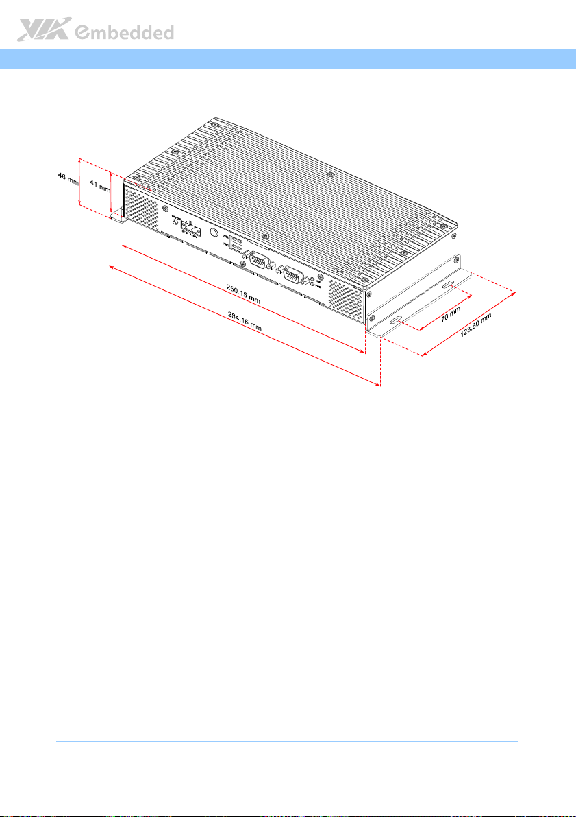
250.15 mm x 41 mm x 123.60 mm
284.15 mm x 46 mm x 123.60 mm (with mounting brackets installed)
1.6 Kg (net weight)
Page 16

AMOS
AMOS----5002
AMOSAMOS
1.2.6. Environment Specifications
Operating Temperature
Operating Temperature
Operating TemperatureOperating Temperature
System Specification
System built-in support of
optional USB 3.0
When System is running
without any storage, but
using PXE Boot from LAN,
the specification of operating
temperature is:
When System is running with
CFast Flash Disk only, the
specification of operating
temperature is:
Part Number
Storage Temperature
Storage Temperature
Storage Temperature Storage Temperature
Relative Humidity
Relative Humidity
Relative HumidityRelative Humidity
Vibration
Vibration During O
Vibration Vibration
Shock
Shock During Operation (with CFast card)
During Operation (with CFast card)
Shock Shock
During Operation (with CFast card)During Operation (with CFast card)
EMC Approv
EMC Approved
EMC ApprovEMC Approv
-20°C up to 60 °C
0% to 90% @ 45°C, non-condensing
During Operation
During ODuring O
5Grms, IEC 60068-2–64, random, 5–500Hz, 1 Oct./min, 1hr/axis
50G, IEC 60068-2–27, half size, 11ms duration
CE, FCC Class A
AMOS-5002-1D10A1 AMOS-5002-1D12A1
No Yes No Yes
-20°C up to 55°C -20°C up to 50°C -20°C up to 50°C -20°C up to 45°C
-20°C up to 50°C
peration (with CFa
perationperation
ed
eded
-20°C up to 45°C -20°C up to 45°C -20°C up to 40°C
(with CFast card)
(with CFa (with CFa
st card)
st card)st card)
5002 User Manual
User Manual
50025002
User ManualUser Manual
1.2.7. Software Compatibility
Operating System
Operating System
Operating SystemOperating System
Microsoft Windows 7
Microsoft Windows XP
Microsoft Windows XP Embedded
Microsoft Windows Embedded Standard 7
Debian Linux 6 (Kernel 2.6.32-5-686)
5
Page 17
AMOS
AMOS----5002
AMOSAMOS
1.3. Product Dimensions
Figure
Figure 1111:
: AMOS
AMOS----5002 Dimensions
: :
AMOSAMOS
5002 Dimensions
5002 Dimensions5002 Dimensions
Figure Figure
5002 User Manual
User Manual
50025002
User ManualUser Manual
6
Page 18
AMOS
2.
2. I/O Interface
I/O Interface
2.2.
I/O InterfaceI/O Interface
The AMOS-3002 has a wide selection of interfaces integrated into the board. It
includes a selection of frequently used ports as part of the external I/O coastline.
AMOS----5002
5002 User Manual
AMOSAMOS
50025002
User Manual
User ManualUser Manual
2.1. External I/O Ports
The AMOS-5002 has external I/O ports placed along both faces of the chassis.
Figure
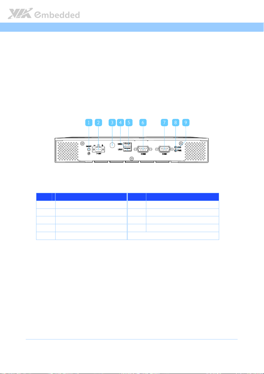
Figure 2222: Front I/O panel
: Front I/O panel
Figure Figure
: Front I/O panel: Front I/O panel
Item
Item Description
ItemItem
Description Item
DescriptionDescription
1 Power button (On/Off) 6 COM2 connector
2 DC power input connector 7 COM1 connector
3 WLAN antenna hole 8 HDD LED indicator
4 USB2.0 port 1 9 Power LED indicator
5 USB2.0 port 2
Item Description
ItemItem
Description
DescriptionDescription
7
Page 19
AMOS
USB3.0 2
USB3.0 1
17 18
10 12 13 14 15 16
11
AMOS----5002
AMOSAMOS
Figur
Figure
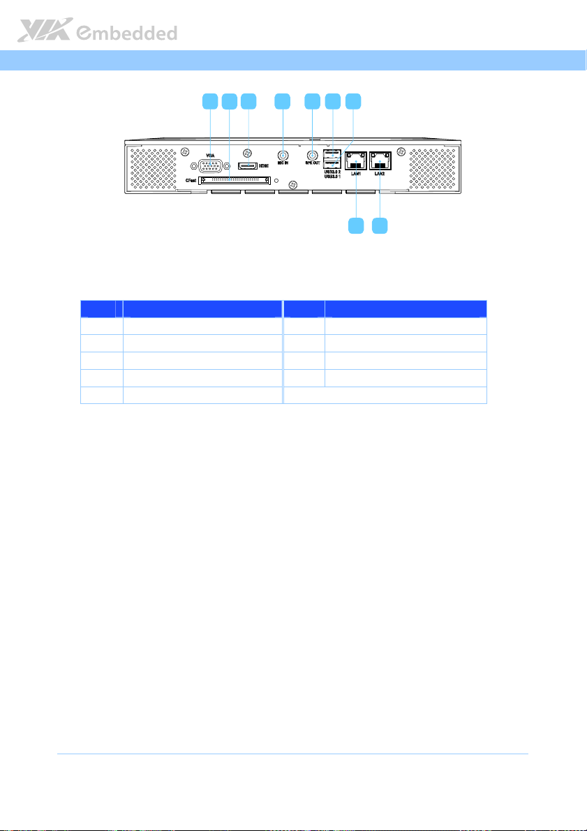
e 3333: Rear I/O panel
: Rear I/O panel
FigurFigur
e e
: Rear I/O panel: Rear I/O panel
Item
Item Description
ItemItem
Description Item
DescriptionDescription
10 VGA connector 15 USB 3.0 port 2
11 CFast socket 16 USB 3.0 port 1
12 HDMI port 17 Gigabit Ethernet port 2 (LAN2)
13 Mic-In jack 18 Gigabit Ethernet port 1 (LAN1)
14 Speaker-Out jack
Item Description
ItemItem
Description
DescriptionDescription
5002 User Manual
User Manual
50025002
User ManualUser Manual
8
Page 20
AMOS
AMOS----5002
5002 User Manual
AMOSAMOS
50025002
User Manual
User ManualUser Manual
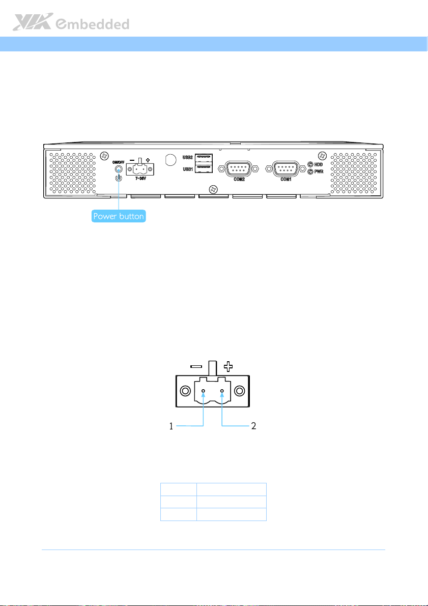
2.1.1. Power Button
The AMOS-5002 comes with a power button on the front panel that supports
two functions: soft power on/off (instant off or delay 4 seconds), and suspend.
Figure
Figure 4444: Power
: Power button
button diagram
Figure Figure
: Power : Power
buttonbutton
diagram
diagram diagram
2.1.2. DC-In Power Input Connector
The AMOS-5002 comes with a 2-pole Phoenix connector on the front panel
that carries 7V
– 36VDC external power input.
DC
Figure
Figure 5555: Power
: Power input
input connector pinout diagram
Figure Figure
: Power : Power
connector pinout diagram
input input
connector pinout diagramconnector pinout diagram
Pin
Table
Table 1111: Power
: Power input
Table Table
: Power : Power
Pin Signal
PinPin
1 GND
2 7VDC ~ 36VDC
input connector pinout
connector pinout
input input
connector pinoutconnector pinout
Signal
SignalSignal
9
Page 21
AMOS
AMOS----5002
5002 User Manual
AMOSAMOS
50025002
User Manual
User ManualUser Manual
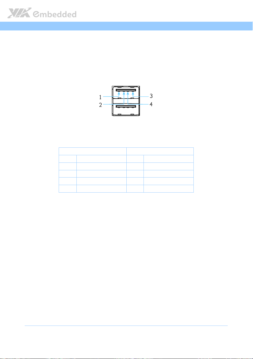
2.1.3. USB 2.0 Ports
The AMOS-5002 has two external USB ports (USB1 and USB2) on the front
panel. Each USB port gives complete Plug and Play and hot swap capability
for external devices. The USB interface complies with USB UHCI, Rev. 2.0.
Figure
Figure 6666:
: USB
USB 2.0
2.0 port
port pinout diagram
Figure Figure
Table
Table 2222:
Table Table
: :
USB USB
: USB
USB 2.0
: :
USB USB
pinout diagram
2.0 2.0
portport
pinout diagram pinout diagram
USB1
USB1 USB2
USB1USB1
Pin
Pin Signal
Signal Pin
PinPin
SignalSignal
1 VCC 1 VCC
2 USB data - 2 USB data -
3 USB data + 3 USB data +
4 GND 4 GND
2.0 port
port ppppinout
port port
inout
inoutinout
2.0 2.0
USB2
USB2USB2
Pin Signal
Signal
PinPin
SignalSignal
10
Page 22
AMOS
AMOS----5002
5002 User Manual
AMOSAMOS
50025002
User Manual
User ManualUser Manual
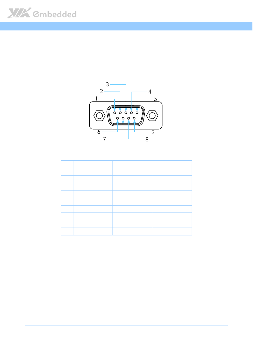
2.1.4. COM Connector
The AMOS-5002 has two D-sub 9-pin male connectors named COM1 and
COM2. The COM1 and COM2 connectors can be configured as RS-232, RS-
422, or RS-485. However, the default setting of COM1 and COM2 connectors
is RS-232. To configure the COM connectors, user needs to setup the BIOS.
Figure
Figure 7777: COM connector pinout diagram
: COM connector pinout diagram
Figure Figure
: COM connector pinout diagram: COM connector pinout diagram
Pin
Pin
RS
RS----232 Signal
PinPin
1 DCD Tx- DATA-
2 RxD Tx+ DATA+
3 TxD Rx+ NC
4 DTR Rx- NC
5 GND GND GND
6 DSR NC NC
7 RTS NC NC
8 CTS NC NC
9 RI NC NC
Table
Table 3333: COM connector pinout
: COM connector pinout
Table Table
: COM connector pinout: COM connector pinout
232 Signal RS
RSRS
232 Signal232 Signal
RS----422 Signal
422 Signal RS
RSRS
422 Signal422 Signal
RS----485 Signal
485 Signal
RSRS
485 Signal485 Signal
11
Page 23
AMOS
AMOS----5002
5002 User Manual
AMOSAMOS
50025002
User Manual
User ManualUser Manual
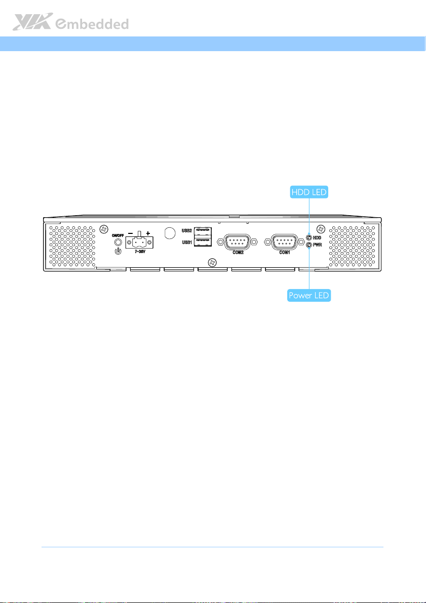
2.1.5. LED Indicators
There are two LEDs on the front panel of the AMOS-5002 that indicate the
status of the system:
PWR LED is green and indicates the status of the system’s power
status.
HDD LED is red and indicates any storage activity for the CFast disk.
Figure
Figure 8888:
: System LED indicators
Figure Figure
System LED indicators
: :
System LED indicatorsSystem LED indicators
12
Page 24
AMOS
AMOS----5002
5002 User Manual
AMOSAMOS
50025002
User Manual
User ManualUser Manual
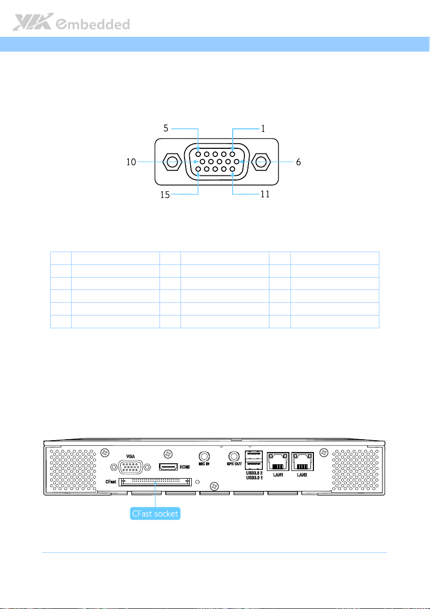
2.1.6. VGA Connector
The AMOS-5002 provides a high resolution VGA interface through DE-15
female connector on the rear I/O panel. It supports resolutions up to 2560 x
1600. The pinout of the VGA connector is shown below.
Figure
Figure 9999: VGA
: VGA connector
Figure Figure
connector pinout diagram
: VGA : VGA
connectorconnector
Pin
Pin
Signal
Signal Pin
PinPin
SignalSignal
1 RED 6 Ground 11 NC
2 GREEN 7 Ground 12 DDC_SPD
3 BLUE 8 Ground 13 HSync
4 NC 9 +5V 14 VSync
5 Ground 10 Ground 15 DDC_SCL
Table
Table 4444: VGA
: VGA connector
Table Table
connector pinout
: VGA : VGA
connectorconnector
pinout diagram
pinout diagram pinout diagram
Pin
PinPin
pinout
pinout pinout
Signal
Signal Pin
SignalSignal
Pin
PinPin
Signal
Signal
SignalSignal
2.1.7. CFast Socket
The AMOS-5002 has CFast socket located on the rear panel. The CFast socket
is compatible with Type I and Type II.
Figure
Figure 10
10:
: CFast socket
Figure Figure
CFast socket diagram
1010
: :
CFast socketCFast socket
13
diagram
diagram diagram
Page 25
AMOS
AMOS----5002
5002 User Manual
AMOSAMOS
50025002
User Manual
User ManualUser Manual
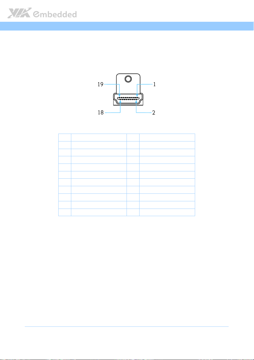
2.1.8. HDMI Port
The AMOS-5002 has one HDMI port (19-pin HDMI Type A receptacle)
connector as defined in the HDMI 1.2 specification. The HDMI port is for
connecting to HDMI displays. The pinout of the HDMI port is shown below.
Figure
Figure 11
11: HDMI port pinout diagram
Figure Figure
Table
Table 5555: HDMI port pinout
Table Table
: HDMI port pinout diagram
1111
: HDMI port pinout diagram: HDMI port pinout diagram
Pin
Pin
Signal
Signal Pin
PinPin
SignalSignal
1 HDMITX2+ 2 GND
3 HDMITX2- 4 HDMITX1+
5 GND 6 HDMITX1-
7 HDMITX0+ 8 GND
9 HDMITX0- 10 HDMITXC+
11 GND 12 HDMITXC-
13 CEC 14 NC
15 SPCLK 16 SPDAT
17 GND 18 PVDD5
19 -DP1_HPD
: HDMI port pinout
: HDMI port pinout: HDMI port pinout
Pin
PinPin
Signal
Signal
SignalSignal
14
Page 26

AMOS
AMOS----5002
5002 User Manual
AMOSAMOS
50025002
User Manual
User ManualUser Manual
2.1.9. Audio Jacks
The AMOS-5002 has two 3.5mm TRS audio jacks for Mic-In and Speaker-Out
on the rear panel. The MIC-In jack is for connecting to a microphone while the
Speaker-Out jack is for connecting to external speakers or headphones.
Figure
Figure 12
12:
: Audio jack receptacle stack
Figure Figure
Table
Table 6666: Audio jack receptacle pinout
Table Table
Audio jack receptacle stack
1212
: :
Audio jack receptacle stackAudio jack receptacle stack
Jack
Jack Description
JackJack
Mic-In TRS jack, 3.5mm Ø 5P, 90 Degree, Female, shielded
Speaker-Out TRS jack, 3.5mm Ø 5P, 90 Degree, Female, shielded
: Audio jack receptacle pinout
: Audio jack receptacle pinout: Audio jack receptacle pinout
Description
DescriptionDescription
15
Page 27

AMOS
AMOS----5002
5002 User Manual
AMOSAMOS
50025002
User Manual
User ManualUser Manual
2.1.10. USB 3.0 Ports
The AMOS-5002 provides two USB 3.0 ports, also known as SuperSpeed USB
on the rear panel. The USB 3.0 has a maximum data transfer rate up to 5 Gbps
and offers a backwards compatible with previous USB 2.0 specifications. Each
USB 3.0 port uses USB Type-A receptacle connector. The pinout of the typical
USB 3.0 port is as shown below.
Figure
Figure 13
13: USB
: USB 3333.0 port pinout diagram
Figure Figure
1313
Table
Table 7777: USB 3.0 port pinout
Table Table
.0 port pinout diagram
: USB : USB
.0 port pinout diagram.0 port pinout diagram
Pi
Pinnnn
Signal
Signal
PiPi
SignalSignal
1 +5V
2 Data-
3 Data+
4 GND
5 Rx-
6 Rx+
7 GND
8 Tx-
9 Tx+
: USB 3.0 port pinout
: USB 3.0 port pinout: USB 3.0 port pinout
16
Page 28

AMOS
AMOS----5002
5002 User Manual
AMOSAMOS
50025002
User Manual
User ManualUser Manual
2.1.11. Gigabit Ethernet Port
The AMOS-5002 system is equipped with two Gigabit Ethernet ports (LAN1
and LAN2) on rear I/O panel. Both ports are fully compliant with IEEE 802.3
(10BASE-T), 802.3u (100BASE-TX), and 802.3ab (1000BASE-T) standards. The
pinout of the LAN1 and LAN2 ports are shown below.
Figure
Figure 14
14: Gigabit Ethernet port pinout diagram
Figure Figure
Table
Table 8888: Gigabit Ethernet port pinout
Table Table
: Gigabit Ethernet port pinout diagram
1414
: Gigabit Ethernet port pinout diagram: Gigabit Ethernet port pinout diagram
LAN1
LAN1 LAN2
LAN1LAN1
Pin
Pin Signal
Signal Pin
PinPin
SignalSignal
1 LAN1_TD0+ 1 LAN2_TD0+
2 LAN1_TD0- 2 LAN2_TD0-
3 LAN1_TD1+ 3 LAN2_TD1+
4 LAN1_TD1- 4 LAN2_TD1-
5 LAN1_TD2+ 5 LAN2_TD2+
6 LAN1_TD2- 6 LAN2_TD3-
7 LAN1_TD3+ 7 LAN2_TD3+
8 LAN1_TD3- 8 LAN2_TD3-
: Gigabit Ethernet port pinout
: Gigabit Ethernet port pinout: Gigabit Ethernet port pinout
LAN2
LAN2LAN2
Pin Signal
Signal
PinPin
SignalSignal
Both LAN1 and LAN2 are equipped with two LED indicators located to show
its active/link status and speed status.
LAN LED Status
LAN LED Status
LAN LED StatusLAN LED Status
Link LED
Active The LED is always On, different LED colors
Link The LED is always On, different LED colors
Speed_10Mbit The LED is always On in Orange color Flash in Orange color
Speed_100 Mbit The LED is always On in Green color Flash in Orange color
Speed_1000 Mbit The LED is always On in Red color Flash in Orange color
Link LED
Link LEDLink LED
(Left LED on RJ
(Left LED on RJ----45 port)
(Left LED on RJ(Left LED on RJ
represent LAN connection speed.
represent LAN connection speed.
45 port)
45 port)45 port)
Active LED
Active LED
Active LEDActive LED
(Right LED on RJ
(Right LED on RJ----45 port)
(Right LED on RJ(Right LED on RJ
Flash in Orange color
LED is off
45 port)
45 port)45 port)
17
Page 29

AMOS
AMOS----5002
AMOSAMOS
5002 User Manual
User Manual
50025002
User ManualUser Manual
18
Page 30

AMOS
USB2
USB1
DC IN 7~36V
COM2
COM1
PWR
HDD
ON/OFF
+
-
3.
3. Hardware Installation
Hardware Installation
3.3.
Hardware InstallationHardware Installation
AMOS----5002
5002 User Manual
AMOSAMOS
50025002
User Manual
User ManualUser Manual
This chapter provides you with information about hardware installation
procedures. It is recommended to use a grounded wrist strap before handling
computer components. Electrostatic discharge (ESD) can damage some
components.
3.1. How to remove the cover
Step 1
Step 1
Step 1Step 1
Remove the eight screws on the top of the chassis.
Step 2
Step 2
Step 2Step 2
Lift up the cover slowly and carefully.
19
Page 31

AMOS
AMOS----5002
5002 User Manual
AMOSAMOS
50025002
User Manual
User ManualUser Manual
3.2. How to install memory module and heatsink
Step 1
Step 1
Step 1Step 1
Align the notch on the memory module with the notch on the SODIMM
socket.
Step 2
Step 2
Step 2Step 2
Insert the memory module into the SODIMM socket at the 30 degree angle.
Then push down until the memory module snaps into place. The SODIMM
socket has two locking mechanisms that will click once the memory module
has been fully inserted.
1 2
ON/OFF
+
DC IN 7~36V
USB2
USB1
COM2
COM1
HDD
PWR
20
Page 32

AMOS
Step 3
Step 3
Step 3Step 3
AMOS----5002
5002 User Manual
AMOSAMOS
50025002
User Manual
User ManualUser Manual
Flip over the top cover chassis. Install the memory heatsink with thermal pad
then secure it with four screws.
Step 4
Step 4
Step 4Step 4
Remove the thermal pad protective cover (plastic) of the memory heatsink.
21
Page 33

AMOS
AMOS----5002
5002 User Manual
AMOSAMOS
50025002
User Manual
User ManualUser Manual
3.3. How to install the WLAN module
Step 1
Step 1
Step 1Step 1
Connect the mini-coaxial antenna cable to the mini RF MAIN connector on Wi-
Fi module.
Step 2
Step 2
Step 2Step 2
Flip over the Wi-Fi module. Install it over the module plate and secure it with
three screws.
22
Page 34

AMOS
Step 3
Step 3
Step 3Step 3
AMOS----5002
5002 User Manual
AMOSAMOS
50025002
User Manual
User ManualUser Manual
Locate the mounting holes for the Wi-Fi module. Remove the two screws on
the mainboard and replace it with two standoff hex screws provided with the
WLAN kit.
Step 4
Step 4
Step 4Step 4
Align the two mounting holes on the Wi-Fi module plate with the mounting
holes on the standoffs hex screws.
Step 5
Step 5
Step 5Step 5
Secure the Wi-Fi module plate (with Wi-Fi module) in place with the screws
provided (x2).
23
Page 35

AMOS
Step
Step 6666
Step Step
AMOS----5002
5002 User Manual
AMOSAMOS
50025002
User Manual
User ManualUser Manual
Attach the board-to-board cable to the Wi-Fi USB pin header (J5 USB2.0) on
the mainboard. The red wire of the cable should be on pin number 2 of the
pin header (J5 USB2.0).
Step 7
Step 7
Step 7Step 7
Gently attach the other end of the board-to-board cable to the Wi-Fi mini
connector on the Wi-Fi module.
24
Page 36

AMOS
Step
Step 8888
Step Step
AMOS----5002
5002 User Manual
AMOSAMOS
50025002
User Manual
User ManualUser Manual
Remove the Wi-Fi antenna hole cover from the front chassis. To facilitate
removing the cover, use a pair of needle-nose pliers to depress both locking
clips simultaneously.
25
Page 37

AMOS
Step
Step 9999
Step Step
AMOS----5002
5002 User Manual
AMOSAMOS
50025002
User Manual
User ManualUser Manual
Insert the antenna cable (provided with the WLAN kit) into the WLAN antenna
hole from the inside. Make sure the flat side of the antenna jack matches the
flat side of the antenna hole.
Step
Step 10
10
Step Step
1010
Secure the WLAN antenna jack to the chassis with the toothed washer and nut.
26
Page 38

AMOS
AMOS----5002
AMOSAMOS
3.4. How to install CFast Card
Step 1
Step 1
Step 1Step 1
Remove the CFast card cover from the front chassis plate.
5002 User Manual
User Manual
50025002
User ManualUser Manual
27
Page 39

AMOS
Step 2
Step 2
Step 2Step 2
AMOS----5002
5002 User Manual
AMOSAMOS
50025002
User Manual
User ManualUser Manual
Insert the CFast card into the CFast socket. Ensure the orientation is correct
before inserting the card.
28
Page 40

AMOS
Step 3
Step 3
Step 3Step 3
AMOS----5002
AMOSAMOS
Install back the CFast socket cover and secure it with screw.
5002 User Manual
User Manual
50025002
User ManualUser Manual
29
Page 41

AMOS
AMOS----5002
5002 User Manual
AMOSAMOS
50025002
User Manual
User ManualUser Manual
3.5. How to install the Mounting Brackets
Step 1
Step 1
Step 1Step 1
Prepare the left and right brackets and the four screws.
Step 2
Step 2
Step 2Step 2
Fasten the mounting brackets to both sides of the AMOS-5002 chassis as
shown below.
30
Page 42

AMOS
Step 3
Step 3
Step 3Step 3
AMOS----5002
5002 User Manual
AMOSAMOS
50025002
Secure both mounting brackets to the wall/table with four screws.
User Manual
User ManualUser Manual
31
Page 43

Page 44

AMOS
4.
4. Jumper Settings
Jumper Settings
4.4.
Jumper SettingsJumper Settings
This section will explain how to configure the AMOS-5002 to match the needs
of your application by setting the jumpers.
AMOS----5002
5002 User Manual
AMOSAMOS
50025002
User Manual
User ManualUser Manual
4.1. Basic Jumper Configuration
The AMOS-5002 internal board provides a jumper for setting some system
hardware functions. The jumper is the simplest kind of electrical switch. It
consists of two metal pins and a small metal clip. It is often protected by a
plastic cover that slides over the pins to connect them. In order to “close” a
jumper, you should connect the pins with the clip. And remove the clip in
order to “open” the jumper. Sometimes a jumper will have three pins which
labeled 1, 2, and 3. In this case, you would connect either pins 1 and 2 or pins
2 and 3.
Figure
Figure 15
15:
: Basic j
Basic jumper configuration
Figure Figure
1515
umper configuration
: :
Basic jBasic j
umper configurationumper configuration
Note:
Note:
Note:Note:
A pair of needle nose pliers may be helpful when setting up the jumpers. If you have any doubts about
the proper hardware configuration for your application, contact your local distributor or sales
representative before you make any changes.
33
Page 45

AMOS
AMOS----5002
5002 User Manual
AMOSAMOS
50025002
User Manual
User ManualUser Manual
4.2. CLEAR_CMOS: Clear CMOS jumper
The onboard CMOS RAM stores system configuration data and has an onboard
battery power supply. To reset the CMOS settings, set the jumper on pins 2
and 3 while the system is off. Return the jumper to pins 1 and 2 afterwards.
Setting the jumper while the system is on will damage the mainboard. The
default setting is on pins 1 and 2.
Figure
Figure 16
16: CLEAR CMOS jumper
Figure Figure
Table
Table 9999: CLEAR CMOS jumper settings
Table Table
: CLEAR CMOS jumper
1616
: CLEAR CMOS jumper: CLEAR CMOS jumper
Setting
Setting 1111 2222 3333
SettingSetting
Normal Operation (default) ON ON OFF
Clear CMOS setting OFF ON ON
: CLEAR CMOS jumper settings
: CLEAR CMOS jumper settings: CLEAR CMOS jumper settings
NNNNote:
Except when clearing the RTC RAM, never remove the CLEAR_CMOS jumper cap from the default
position. Removing the cap will cause system boot failure. Avoid clearing the CMOS while the system
is on; it will damage the mainboard.
34
Page 46

AMOS
AMOS----5002
5002 User Manual
AMOSAMOS
50025002
User Manual
User ManualUser Manual
4.3. COM Voltage Select Jumpers
The voltage select jumpers “JCOMV1 and JCOMV2” are set to determine the
input carry voltage or Wake-on-ring signal of COM1 and COM2 connectors on
the front panel. The control signal Ring Indicator (RI) is the default setting. The
jumper settings are shown below.
Figure
Figure 17
17: JCOMV1 and JCOMV2 voltage select jumpers
Figure Figure
: JCOMV1 and JCOMV2 voltage select jumpers
1717
: JCOMV1 and JCOMV2 voltage select jumpers: JCOMV1 and JCOMV2 voltage select jumpers
JCOMV1 Setting
JCOMV1 Setting
JCOMV1 SettingJCOMV1 Setting
RI (default) Off Off Off RI (default) Off Off Off
+5V On On Off +5V On On Off
+12V Off On On
Table
Table 10
10: JCOMV1 and JCOMV2 voltage select jumper settings
: JCOMV1 and JCOMV2 voltage select jumper settings
Table Table
1010
: JCOMV1 and JCOMV2 voltage select jumper settings: JCOMV1 and JCOMV2 voltage select jumper settings
Pin 1
Pin 1
Pin 1Pin 1
Pin 2
Pin 2
Pin 2Pin 2
Pin 3
Pin 3
Pin 3Pin 3
JCOMV2 Setting
JCOMV2 Setting
JCOMV2 SettingJCOMV2 Setting
+12V Off On On
Pin 1
Pin 1
Pin 1Pin 1
Pin 2
Pin 2
Pin 2Pin 2
Pin 3
Pin 3
Pin 3Pin 3
35
Page 47

Page 48

AMOS
5.
5. BIOS Setup
BIOS Setup
5.5.
BIOS SetupBIOS Setup
This chapter gives a detailed explanation of the BIOS setup functions.
AMOS----5002
5002 User Manual
AMOSAMOS
50025002
User Manual
User ManualUser Manual
5.1. Entering the BIOS Setup Menu
Power on the computer and press Delete
sequence to enter the BIOS setup menu. If you missed the BIOS setup entry
point, restart the system and try again.
Delete during the beginning of the boot
DeleteDelete
5.2. Control Keys
Up
Up Move up one row
UpUp
Down
Down Move down one row
DownDown
Left
Left Move to the left in the navigation bar
LeftLeft
Right
Right Move to the right in the navigation bar
RightRight
Enter
Enter Access the highlighted item
EnterEnter
Esc
Esc Jumps to the Exit screen or returns to the previous screen
EscEsc
1
++++
Increase the numeric value
1
Decrease the numeric value
----
F1
F1 General help
F1F1
F7
F7 Discard changes
F7F7
F9
F9 Load optimized defaults
F9F9
2
F10
F10 Save all the changes and exit
F10F10
Note:
Note:
Note:Note:
1. Must be pressed using the 10-key pad.
2. The General help contents are only for the Status Page and Option Page setup menus.
37
Page 49

AMOS
AMOS----5002
5002 User Manual
AMOSAMOS
50025002
User Manual
User ManualUser Manual
5.3. Getting Help
The BIOS Setup Utility provides a “General Help” screen. This screen can be
accessed at any time by pressing F1
using and navigating the BIOS Setup Utility. Press Esc
F1. The help screen displays the keys for
F1F1
Esc to exit the help screen.
EscEsc
38
Page 50

AMOS
System Time [1 : 42 : 06]
System Overview
Version : 08.00.16
Use [ENTER], [TAB] or
[SHIFT-TAB] to select
a field.
Use [+] or [-] to
configure system time.
System Date [Tue 09/21/2011]
AMIBIOS
Build Date : 9/20/11
ID : X0300100
VIA Nano X2 U4300 @ 1.2+ GHz
Processor
Size : 3840MB
System Memory
BIOS SETUP UTILITY
V02.69 (C) Copyright 1985-2010, American Megatrends, Inc.
+ Tab
F1
F10
ESC
Select Screen
Select Item
Change Field
Select Field
General Help
Save and Exit
Exit
Main Advanced Boot Security Chipset Exit
AMOS----5002
5002 User Manual
AMOSAMOS
50025002
User Manual
User ManualUser Manual
5.4. System Overview
The System Overview screen is the default screen that is shown when the
BIOS Setup Utility is launched. This screen can be accessed by traversing the
navigation bar to the “Main” label.
Figure
Figure 18
18: Illustration of the Main menu screen
Figure Figure
: Illustration of the Main menu screen
1818
: Illustration of the Main menu screen: Illustration of the Main menu screen
5.4.1. AMIBIOS
The content in this section of the screen shows the current BIOS version, build
date, and ID number.
5.4.2. Processor
This content in this section shows the CPU information that has been detected.
5.4.3. System Memory
This section shows the amount of available memory that has been detected.
39
Page 51

AMOS
AMOS----5002
5002 User Manual
AMOSAMOS
50025002
User Manual
User ManualUser Manual
5.4.4. System Time
This section shows the current system time. Press Tab
Shift+Tab
Shift+Tab to traverse left through the hour, minute, and second segments. The
Shift+TabShift+Tab
++++ and ---- keys on the number pad can be used to change the values. The time
format is [Hour : Minute : Second].
Tab to traverse right and
TabTab
5.4.5. System Date
This section shows the current system date. Press Tab
Shift+Tab
Shift+Tab to traverse left through the month, day, and year segments. The ++++
Shift+TabShift+Tab
and ---- keys on the number pad can be used to change the values. The weekday
name is automatically updated when the date is altered. The date format is
[Weekday, Month, Day, Year].
Tab to traverse right and
TabTab
40
Page 52

AMOS
Advanced Settings
Configure CPU.
WARNING :
Setting wrong values in below sections
may cause system to malfunction.
CPU Configuration
ACPI Configuration
APM Configuration
Spread Spectrum Configuration
USB Configuration
SuperIO Configuration
Hardware Health Configuration
CRB Configuration
SATA Configuration
FreeDos Configuration
BIOS SETUP UTILITY
V02.69 (C) Copyright 1985-2010, American Megatrends, Inc.
Enter
F1
F10
ESC
Select Screen
Select Item
Go to Sub Screen
General Help
Save and Exit
Exit
Main Advanced Boot Security Chipset Exit
AMOS----5002
5002 User Manual
AMOSAMOS
50025002
User Manual
User ManualUser Manual
5.5. Advanced Settings
The Advanced Settings screen shows a list of categories that can provide
access to a sub-screen. Sub-screen links can be identified by the preceding
right-facing arrowhead.
Figure
Figure 19
19: Illustration of the Advanced Settings screen
Figure Figure
The Advanced Settings screen contains the following links:
: Illustration of the Advanced Settings screen
1919
: Illustration of the Advanced Settings screen: Illustration of the Advanced Settings screen
CPU Configuration
SATA Configuration
SuperIO Configuration
Hardware Health Configuration
ACPI Configuration
APM Configuration
Spread Spectrum Configuration
USB Configuration
FreeDos Configuration
CRB Configuration
41
Page 53

AMOS
Configure advanced CPU settings
Manufacturer : VIA
VIA Nano X2 U4300 @ 1.2+ GHz
Speed (FSB 266MHz * 4.5): 1200MHz
Core : 2
Cache L1 : 128 KB
Cache L2 : 1024 KB
Module Version: 01.0C
Microcode revision : 26
Advanced
Enabled/Disabled
Nano CPU Thermal
Monitor 3 function
PMON Support : N/A
PMON [Disabled]
BIOS SETUP UTILITY
V02.69 (C) Copyright 1985-2010, American Megatrends, Inc.
+ F1
F10
ESC
Select Screen
Select Item
Change Option
General Help
Save and Exit
Exit
AMOS----5002
5002 User Manual
AMOSAMOS
50025002
User Manual
User ManualUser Manual
5.5.1. CPU Configuration
The CPU Configuration screen shows detailed information about the built-in
processor.
Figure
Figure 20
20: Illustration of the CPU Configuration screen
Figure Figure
5.5.1.1.
5.5.1.1. PMON
5.5.1.1.5.5.1.1.
The PMON function has two settings: Auto and Disabled. When set to “Auto”,
the PMON function will be enabled and controlled the CPU speed to perform
automatically at best performance to comply with the given system
applications. The PMON default setting is Disabled.
: Illustration of the CPU Configuration screen
2020
: Illustration of the CPU Configuration screen: Illustration of the CPU Configuration screen
PMON
PMONPMON
Note:
Note:
Note:Note:
Enabling the PMON function have an effect on the PXE and CFast operating temperature that would
rise up to 60°C (for EITX-3002-1D10A1 and EITX-3002-2D10A1) and 50°C (for EITX-3002-1D12A1 and
EITX-3002-2D12A1). Also, it could possibly affect the RTC time value.
42
Page 54

AMOS
SATA Configuration
While entering setup,
BIOS auto detects the
presence of SATA devices.
This displays the status
of auto detection of SATA
devices.
Serial ATA IDE devices
Advanced
Primary IDE Master : [Hard Disk]
Primary IDE Slave : [Not Detected]
BIOS SETUP UTILITY
V02.69 (C) Copyright 1985-2010, American Megatrends, Inc.
Enter
F1
F10
ESC
Select Screen
Select Item
Go to Sub Screen
General Help
Save and Exit
Exit
Primary IDE Master
Select the type of
device connected to the
system.
Advanced
Device : Hard Disk
Vendor : Hitachi HTS545025B9A300
Size : 250.0 GB
LBA Mode : Supported
Block Mode : 16 Sectors
PIO Mode : 4
Async DMA : MultiWord DMA-2
Ultra DMA : Ultra DMA-6
S.M.A.R.T. : Supported
BIOS SETUP UTILITY
V02.69 (C) Copyright 1985-2010, American Megatrends, Inc.
+ F1
F10
ESC
Select Screen
Select Item
Change Option
General Help
Save and Exit
Exit
AMOS----5002
5002 User Manual
AMOSAMOS
50025002
User Manual
User ManualUser Manual
5.5.2. SATA Configuration
The SATA Configuration screen shows links to the primary IDE Master and
primary IDE Slave hard drive information screens.
Figure
Figure 21
21: Illustration of SATA Configuration screen
Figure Figure
5.5.2.1.
5.5.2.1. Hard Disk Information
5.5.2.1.5.5.2.1.
When a hard drive is detected, the hard drive’s detailed information can be
displayed on the Primary IDE Master/Slave sub-screen.
: Illustration of SATA Configuration screen
2121
: Illustration of SATA Configuration screen: Illustration of SATA Configuration screen
Hard Disk Information
Hard Disk InformationHard Disk Information
Figure
Figure 22
22: Illustration of Primary IDE Master screen
Figure Figure
: Illustration of Primary IDE Master screen
2222
: Illustration of Primary IDE Master screen: Illustration of Primary IDE Master screen
43
Page 55

AMOS
Configure F81865F Super IO Chipset
Allows BIOS to select
Serial Port1 base
addresses.
Serial Port [3F8/IRQ4]
Advanced
Serial Port1 Type [RS232]
Serial Port2 [2F8/IRQ4]
Serial Port2 Type [RS232]
Serial Port3 [3E8/IRQ4]
Serial Port4 [2E8/IRQ4]
Parallel Port [378/IRQ7]
Parallel Port Mode [Normal]
BIOS SETUP UTILITY
V02.69 (C) Copyright 1985-2010, American Megatrends, Inc.
+ F1
F10
ESC
Select Screen
Select Item
Change Option
General Help
Save and Exit
Exit
AMOS----5002
5002 User Manual
AMOSAMOS
50025002
User Manual
User ManualUser Manual
5.5.3. SuperIO Configuration
The SuperIO Configuration screen shows the specific addresses, IRQs and
types of the onboard serial ports.
Figure
Figure 23
23: Illustration of SuperIO
Figure Figure
5.5.3.1.
5.5.3.1. Serial Ports 1 to 4
5.5.3.1.5.5.3.1.
Table
Table 11
Table Table
: Illustration of SuperIO Configuration screen
2323
: Illustration of SuperIO : Illustration of SuperIO
Serial Ports 1 to 4
Serial Ports 1 to 4Serial Ports 1 to 4
Port
Port Address
PortPort
1 Disabled, 3F8 4 RS232, RS422, RS485
2 Disabled, 2F8 4 RS232, RS422, RS485
3 Disabled, 3E8 4 -
4 Disabled, 2E8 4 -
11: Serial port addresses, IRQs and types
: Serial port addresses, IRQs and types
1111
: Serial port addresses, IRQs and types: Serial port addresses, IRQs and types
Configuration screen
Configuration screenConfiguration screen
Address IRQ
Address Address
IRQ Type
IRQIRQ
Type
TypeType
5.5.3.2.
5.5.3.2. Parallel Port
5.5.3.2.5.5.3.2.
Parallel Port
Parallel PortParallel Port
This specifies the I/O port address and IRQ of the parallel port. The parallel
port has two options: Disabled, 378/IRQ7
5.5.3.3.
5.5.3.3. Parallel Port Mode
5.5.3.3.5.5.3.3.
Parallel Port Mode
Parallel Port ModeParallel Port Mode
This specifies the parallel port mode. The parallel port mode has five options:
Normal, Bi-Directional, ECP, EPP, ECP&EPP
44
Page 56

AMOS
Hardware Health Configuration
System Temperature :N/A
VCORE :0.968 V
+5V :4.918 V
+1.5VDIMM :1.502 V
Advanced
CPU Temperature :33°C/91°F
+3.3V :3.352 V
System Fan Speed :N/A
VBAT :3.328V
VSB :3.328V
+12V :12.232 V
BIOS SETUP UTILITY
V02.69 (C) Copyright 1985-2010, American Megatrends, Inc.
+ F1
F10
ESC
Select Screen
Select Item
Change Option
General Help
Save and Exit
Exit
AMOS----5002
5002 User Manual
AMOSAMOS
50025002
User Manual
User ManualUser Manual
5.5.4. Hardware Health Configuration
The Hardware Health Configuration screen displays the monitored aspects of
the mainboard such as CPU temperature, fan speed, and voltages of the power
planes.
Figure
Figure 24
24. Illust
. Illustration of Hardware Health Configuration screen
Figure Figure
ration of Hardware Health Configuration screen
2424
. Illust. Illust
ration of Hardware Health Configuration screenration of Hardware Health Configuration screen
45
Page 57

AMOS
ACPI Settings
Select the ACPI state used
for System Suspend
Suspend mode [Auto]
Advanced
ACPI Version Features [ACPI v3.0]
ACPI APIC Support [Enabled]
USB S4 WakeUp [Disabled]
BIOS SETUP UTILITY
V02.69 (C) Copyright 1985-2010, American Megatrends, Inc.
+ F1
F10
ESC
Select Screen
Select Item
Change Option
General Help
Save and Exit
Exit
AMOS----5002
5002 User Manual
AMOSAMOS
50025002
User Manual
User ManualUser Manual
5.5.5. ACPI Configuration
ACPI grants the operating system direct control over system power
management. The ACPI Configuration screen can be used to set a number of
power management related functions.
Figure
Figure 25
25: Illustration of ACPI Configuration screen
Figure Figure
5.5.5.1.
5.5.5.1. Suspend Mode
5.5.5.1.5.5.5.1.
The Suspend Mode field has three selectable options.
: Illustration of ACPI Configuration screen
2525
: Illustration of ACPI Configuration screen: Illustration of ACPI Configuration screen
Suspend Mode
Suspend ModeSuspend Mode
S1(POS)
S1(POS)
S1(POS)S1(POS)
S1/Power On Suspend (POS) is a low power state. In this state, no system
context (CPU or chipset) is lost and hardware maintains all system contexts.
S3(STR)
S3(STR)
S3(STR)S3(STR)
S3/Suspend To RAM (STR) is a power-down state. In this state, power is
supplied only to essential components such as main memory and wakeup-
capable devices. The system context is saved to main memory, and context is
restored from the memory when a "wakeup" event occurs.
Auto
Auto
AutoAuto
When the Suspend Mode is set to Auto, the operating system will control the
power state.
46
Page 58

AMOS
5.5.5.2.
5.5.5.2. ACPI Version Features
5.5.5.2.5.5.5.2.
The ACPI Version Features enables the BIOS to support the designated ACPI
specification. There are three versions to choose from: ACPI v1.0, ACPI v2.0,
and ACPI v3.0.
5.5.5.3.
5.5.5.3. ACPI APIC Support
5.5.5.3.5.5.5.3.
The ACPI APIC Supports enables the ACPI support in APIC. The ACPI APIC
Supports has two options: Enabled and Disabled. When select Enabled, the
ACPI APIC table pointer includes in the Root System Description Table (RSDT)
pointer lists. When select the Disabled, support for this feature will be
unavailable.
5.5.5.4.
5.5.5.4. USB S4 WakeUp
5.5.5.4.5.5.5.4.
The USB S4 WakeUp enables the system to resume through the USB device
port from S4 state. There are two options: Enabled, Disabled.
ACPI Version Features
ACPI Version FeaturesACPI Version Features
ACPI APIC Support
ACPI APIC SupportACPI APIC Support
USB S4 WakeUp
USB S4 WakeUpUSB S4 WakeUp
AMOS----5002
5002 User Manual
AMOSAMOS
50025002
User Manual
User ManualUser Manual
47
Page 59

AMOS
Options
Advanced
On/Off
Standby
Suspend
Power Button Mode [On/Off]
Advanced Resume Event Controls
Restore on AC/Power Loss [Power-off]
Resume On RTC Alarm [Disabled]
BIOS SETUP UTILITY
V02.69 (C) Copyright 1985-2010, American Megatrends, Inc.
+ F1
F10
ESC
Select Screen
Select Item
Change Option
General Help
Save and Exit
Exit
AMOS----5002
5002 User Manual
AMOSAMOS
50025002
User Manual
User ManualUser Manual
5.5.6. APM Configuration
APM enables the operating system to co-work with the BIOS to control the
system power management. The APM Configuration screen can be used to set
a number of power management functions.
Figure
Figure 26
26: Illustration of APM Configuration screen
Figure Figure
5.5.6.1.
5.5.6.1. Power Button Mode
5.5.6.1.5.5.6.1.
The Power Button Mode has three options.
: Illustration of APM Configuration screen
2626
: Illustration of APM Configuration screen: Illustration of APM Configuration screen
Power Button Mode
Power Button ModePower Button Mode
On/Off
On/Off
On/OffOn/Off
When On/Off is selected, pressing the power button will instantly cause the
system to power on or off.
Standby
Standby
StandbyStandby
When Standby is selected, the power button must be pressed and held down
for 4 seconds before the system will power off.
Suspend
Suspend
SuspendSuspend
When Suspend is selected, pressing the power button will instantly cause the
system to enter suspend mode.
48
Page 60

AMOS
5.5.6.2.
5.5.6.2. Restore on AC/Power L
5.5.6.2.5.5.6.2.
Restore on AC/Power Loss defines how the system will respond after AC
power has been interrupted while the system is on. There are three options.
Power Off
Power Off
Power OffPower Off
The Power Off option keeps the system in an off state until the power button
is pressed again.
PPPPower On
ower On
ower Onower On
The Power On option restarts the system when the power has returned.
Last State
Last State
Last StateLast State
The Last State option restores the system to its previous state when the power
was interrupted.
5.5.6.3.
5.5.6.3. Resume on LAN
5.5.6.3.5.5.6.3.
Resume on LAN wakes up a system that has been put into suspend or standby
mode. When this feature is enabled, the system can be restored to an active
state when a PCIE wake up signal is detected on the LAN.
5.5.6.4.
5.5.6.4. Resume on RTC Alarm
5.5.6.4.5.5.6.4.
Resume on RTC Alarm can only be used if Resume on Software RTC Alarm
not enabled. This feature enables the BIOS to automatically power on the
system at a scheduled time. When enabled, the RTC Alarm Date
Time
Time features will be unlocked.
TimeTime
Restore on AC/Power Loss
Restore on AC/Power LRestore on AC/Power L
Resume on LAN
Resume on LANResume on LAN
Resume on RTC Alarm
Resume on RTC AlarmResume on RTC Alarm
oss
ossoss
Resume on Software RTC Alarm is
Resume on Software RTC AlarmResume on Software RTC Alarm
RTC Alarm Date and System
RTC Alarm DateRTC Alarm Date
AMOS----5002
5002 User Manual
AMOSAMOS
50025002
User Manual
User ManualUser Manual
System
System System
5.5.6.5.
5.5.6.5. RTC Alarm Date (Days)
5.5.6.5.5.5.6.5.
The RTC Alarm Date feature is visible only when Resume on RTC Alarm
enabled. This feature enables the user to specify a specific date each month or
daily recurrence. Use the ++++ and ---- keys on the number pad to change the value
of the RTC Alarm Date.
Every Day
Every Day
Every DayEvery Day
The Every Day option triggers the RTC Alarm daily.
RTC Alarm Date (Days)
RTC Alarm Date (Days)RTC Alarm Date (Days)
Resume on RTC Alarm is
Resume on RTC AlarmResume on RTC Alarm
49
Page 61

AMOS
1
1 –––– 31
31
1 1
31 31
When a specific numeric date is selected, the RTC Alarm will be triggered on
that day of the month.
5.5.6.6.
5.5.6.6. System Time
5.5.6.6.5.5.6.6.
The System Time option enables the user to specify the time the system
should power on for the date that is set in RTC Alarm Date
System Time
System TimeSystem Time
RTC Alarm Date.
RTC Alarm DateRTC Alarm Date
AMOS----5002
5002 User Manual
AMOSAMOS
50025002
User Manual
User ManualUser Manual
50
Page 62

AMOS
Spread Spectrum Configuration
Dynamic to adjust SSC.
Spread Spectrum Configuration [0.1%]
Advanced
BIOS SETUP UTILITY
V02.69 (C) Copyright 1985-2010, American Megatrends, Inc.
+ F1
F10
ESC
Select Screen
Select Item
Change Option
General Help
Save and Exit
Exit
AMOS----5002
5002 User Manual
AMOSAMOS
50025002
User Manual
User ManualUser Manual
5.5.7. Spread Spectrum Configuration
The Spread Spectrum Configuration screen enables access to the Spread
Spectrum Setting feature.
Figure
Figure 27
27: Illustration of Spread Spectrum Configuration screen
Figure Figure
5.5.7.1.
5.5.7.1. Spread Spectrum Setting
5.5.7.1.5.5.7.1.
The Spread Spectrum Setting feature enables the BIOS to modulate the clock
frequencies originating from the mainboard. The settings are in percentages of
modulation. Higher percentages result in greater modulation of clock
frequencies. This feature has settings that range from 0.1% to 0.9%.
: Illustration of Spread Spectrum Configuration screen
2727
: Illustration of Spread Spectrum Configuration screen: Illustration of Spread Spectrum Configuration screen
Spread Spectrum Setting
Spread Spectrum SettingSpread Spectrum Setting
51
Page 63

AMOS
USB Configuration
Advanced
Enables support for legacy
USB. AUTO option disables
legacy support if no USB
devices are connected.
Module Version - 2.24.5-13.4
USB Devices Enabled :
1 Keyboard, 1 Mouse, 1 Hub
USB 2.0 Controller Mode [HiSpeed]
== Onboard VX900 USB Setup Items ==
Legacy USB Support [Enabled]
BIOS SETUP UTILITY
V02.69 (C) Copyright 1985-2010, American Megatrends, Inc.
+ F1
F10
ESC
Select Screen
Select Item
Change Option
General Help
Save and Exit
Exit
AMOS----5002
5002 User Manual
AMOSAMOS
50025002
User Manual
User ManualUser Manual
5.5.8. USB Configuration
The USB Configuration screen shows the number of connected USB devices.
Additionally, support for various USB features can be enabled or disabled.
Figure
Figure 28
28: Illustration of USB Configuration screen
Figure Figure
5.5.8.1.
5.5.8.1. Legacy USB
5.5.8.1.5.5.8.1.
The Legacy USB Support feature has two options: Enabled and Auto. When set
to Enabled, the system enables support for legacy USB devices. When set to
Auto, the system automatically disables legacy support if no USB Devices are
connected.
: Illustration of USB Configuration screen
2828
: Illustration of USB Configuration screen: Illustration of USB Configuration screen
Legacy USB Support
Legacy USBLegacy USB
Support
Support Support
5.5.8.2.
5.5.8.2. USB 2.0 C
5.5.8.2.5.5.8.2.
USB 2.0 Controller Mode
USB 2.0 CUSB 2.0 C
ontroller Mode
ontroller Modeontroller Mode
Configures the USB 2.0 controller in FullSpeed or HiSpeed. The FullSpeed
limit the USB 2.0 controller to transfer data at 12 Mbps. The HiSpeed enables
the USB 2.0 controller to transfer data at 480Mbps. The connected USB device
must support HiSpeed in order to benefit from this setting.
52
Page 64

AMOS
FreeDos Configuration
FreeDos [Disabled]
Advanced
BIOS SETUP UTILITY
V02.69 (C) Copyright 1985-2010, American Megatrends, Inc.
+ F1
F10
ESC
Select Screen
Select Item
Change Option
General Help
Save and Exit
Exit
AMOS----5002
5002 User Manual
AMOSAMOS
50025002
User Manual
User ManualUser Manual
5.5.9. FreeDos Configuration
The FreeDos Configuration screen can be used to enable the FreeDos function.
Figure
Figure 29
29: Illustration of FreeDos Configuration screen
Figure Figure
5.5.9.1.
5.5.9.1. FreeDos
5.5.9.1.5.5.9.1.
The FreeDos feature enables the BIOS to support FreeDos. The options are
Enabled and Disabled.
: Illustration of FreeDos Configuration screen
2929
: Illustration of FreeDos Configuration screen: Illustration of FreeDos Configuration screen
FreeDos
FreeDosFreeDos
53
Page 65

AMOS
Advanced
Options
Disabled
Enabled
VT6130 LAN Control [Enabled]
LAN Option ROM [Disabled]
CRB Configuration
BIOS SETUP UTILITY
V02.69 (C) Copyright 1985-2010, American Megatrends, Inc.
+ F1
F10
ESC
Select Screen
Select Item
Change Option
General Help
Save and Exit
Exit
AMOS----5002
5002 User Manual
AMOSAMOS
50025002
User Manual
User ManualUser Manual
5.5.10. CRB Configuration
The CRB Configuration screen includes chipset settings.
Figure
Figure 30
30: Illustration of CRB Configuration screen
Figure Figure
5.5.10.1.
5.5.10.1. VT6130 LAN Control
5.5.10.1.5.5.10.1.
The VT6130 LAN Control feature determines whether the onboard LAN
controller will be used or not.
: Illustration of CRB Configuration screen
3030
: Illustration of CRB Configuration screen: Illustration of CRB Configuration screen
VT6130 LAN Control
VT6130 LAN ControlVT6130 LAN Control
5.5.10.2.
5.5.10.2. LAN Option ROM
5.5.10.2.5.5.10.2.
LAN Option ROM
LAN Option ROMLAN Option ROM
The LAN Option ROM feature will only be visible if the VT6130 LAN Control
feature is enabled. If the LAN Option ROM feature is enabled, then the system
will load a separate ROM for the LAN controller in order to boot through the
Gigabit Ethernet.
54
VT6130 LAN Control
VT6130 LAN ControlVT6130 LAN Control
Page 66

AMOS
Boot Settings
Configure Settings
during System Boot.
Boot Settings Configuration
Boot Device Priority
BIOS SETUP UTILITY
V02.69 (C) Copyright 1985-2010, American Megatrends, Inc.
Enter
F1
F10
ESC
Select Screen
Select Item
Go to Sub Screen
General Help
Save and Exit
Exit
Main Advanced Boot Security Chipset Exit
Boot
Boot Settings Configuration
Allows BIOS to skip
certain tests while
booting. This will
decrease the time needed
to boot the system.
Quick Boot [Enabled]
Quiet Boot [Enabled]
Bootup Num-Lock [On]
Wait for 'F1' if Error [Enabled]
Hit 'DEL' Message Display [Enabled]
BIOS SETUP UTILITY
V02.69 (C) Copyright 1985-2010, American Megatrends, Inc.
+ F1
F10
ESC
Select Screen
Select Item
Change Option
General Help
Save and Exit
Exit
AMOS----5002
AMOSAMOS
5.6. Boot Settings
5002 User Manual
User Manual
50025002
User ManualUser Manual
The Boot Settings screen has two links that goes to the Boot Settings
Configuration
Configuration and Boot Device Priority
ConfigurationConfiguration
Boot Device Priority screens.
Boot Device Priority Boot Device Priority
Boot Settings
Boot Settings Boot Settings
Figure
Figure 31
31: Illustration of Boot Settings screen
Figure Figure
: Illustration of Boot Settings screen
3131
: Illustration of Boot Settings screen: Illustration of Boot Settings screen
5.6.1. Boot Settings Configuration
The Boot Settings Configuration screen has several features that can be run
during the system boot sequence.
Figure
Figure 32
32: Illustration of Boot Sett
Figure Figure
: Illustration of Boot Settings Configuration screen
3232
: Illustration of Boot Sett: Illustration of Boot Sett
ings Configuration screen
ings Configuration screenings Configuration screen
55
Page 67

AMOS
5.6.1.1.
5.6.1.1. Quick Boot
5.6.1.1.5.6.1.1.
The Quick Boot feature enables the BIOS to skip certain tests in order to
speed up the boot sequence. This feature has two options: enabled and
disabled.
5.6.1.2.
5.6.1.2. Quiet Boot
5.6.1.2.5.6.1.2.
The Quiet Boot feature hides all of the Power-on Self Test (POST) messages
during the boot sequence. Instead of the POST messages, the user will see an
OEM logo. This feature has two options: enabled and disabled.
5.6.1.3.
5.6.1.3. Bootup Num
5.6.1.3.5.6.1.3.
The Bootup Num-Lock feature determines how the 10-key pad will behave.
When the feature is enabled, the 10-key pad will behave as a number pad.
When the feature is disabled, the 10-key pad will behave as cursor navigation
keys.
5.6.1.4.
5.6.1.4. Wait for ‘F1’ if Error
5.6.1.4.5.6.1.4.
This feature determines how the system will respond if an error is detected
during the boot sequence. If this feature is enabled, the BIOS will pause
booting and wait for the user to press F1 to enter the BIOS setup menu. This
feature has two options: enabled and disabled.
Quick Boot
Quick BootQuick Boot
Quiet Boot
Quiet BootQuiet Boot
Bootup Num----Lock
Bootup NumBootup Num
Wait for ‘F1’ if Error
Wait for ‘F1’ if ErrorWait for ‘F1’ if Error
Lock
LockLock
AMOS----5002
5002 User Manual
AMOSAMOS
50025002
User Manual
User ManualUser Manual
5.6.1.5.
5.6.1.5. Hit ‘DEL’ Message Display
5.6.1.5.5.6.1.5.
This feature determines if the BIOS will display a POST message that informs
the user how to access the BIOS Setup Utility.
enabled and disabled.
Hit ‘DEL’ Message Display
Hit ‘DEL’ Message DisplayHit ‘DEL’ Message Display
1
This feature has two options:
Note:
Note:
Note:Note:
1. if the Quiet Boot option is enabled, the settings of this feature will have no effect.
56
Page 68

AMOS
Boot Device Priority
Specifies the best
sequence from the
available devices.
A device enclosed in
parenthesis has been
disabled in the
corresponding type menu.
1st Boot Device [SATA: PM-Hitachi HT]]
Boot
BIOS SETUP UTILITY
V02.69 (C) Copyright 1985-2010, American Megatrends, Inc.
+ F1
F10
ESC
Select Screen
Select Item
Change Option
General Help
Save and Exit
Exit
AMOS----5002
5002 User Manual
AMOSAMOS
50025002
User Manual
User ManualUser Manual
5.6.2. Boot Device Priority
The Boot Device Priority screen lists all bootable devices.
Figure
Figure 33
33: Illustration of the Boot Device Priority screen
Figure Figure
5.6.2.1.
5.6.2.1. 1
5.6.2.1.5.6.2.1.
This feature specifies the boot sequence from the available devices. The
available boot devices are detected dynamically and bootable devices will be
listed accordingly.
: Illustration of the Boot Device Priority screen
3333
: Illustration of the Boot Device Priority screen: Illustration of the Boot Device Priority screen
st
st
stst
1
Boot Device
Boot Device
11
Boot Device Boot Device
57
Page 69

AMOS
Security Settings
Install or Change the
password.
Supervisor Password : Not Installed
Change Supervisor Password
BIOS SETUP UTILITY
V02.69 (C) Copyright 1985-2010, American Megatrends, Inc.
Enter
F1
F10
ESC
Select Screen
Select Item
Change
General Help
Save and Exit
Exit
Main Advanced Boot Security Exit
AMOS----5002
5002 User Manual
AMOSAMOS
50025002
User Manual
User ManualUser Manual
5.7. Security Settings
The Security Settings screen provides a way to restrict access to the BIOS or
even the entire system.
Figure
Figure 34
34: Illustration of Secu
Figure Figure
: Illustration of Security Settings screen
3434
: Illustration of Secu: Illustration of Secu
5.7.1. Change Supervisor Password
This option is for setting a password for accessing the BIOS setup utility.
When a password has been set, a password prompt will be displayed
whenever the BIOS setup utility is launched. This prevents an unauthorized
person from changing any part of the system configuration.
rity Settings screen
rity Settings screenrity Settings screen
When a supervisor password is set, the Password Check
unlocked.
5.7.2. User Access Level
This feature controls the level of access a user (without the supervisor
password) is granted to the BIOS setup utility. This feature has four options.
No Access
No Access
No AccessNo Access
The No Access option completely locks the BIOS setup utility. The supervisor
password is required to access and change the BIOS settings.
58
Password Check option will be
Password CheckPassword Check
Page 70

AMOS
View Only
View Only
View OnlyView Only
AMOS----5002
5002 User Manual
AMOSAMOS
50025002
User Manual
User ManualUser Manual
The View Only option only allows access to view the BIOS settings. Users
with this permission level cannot make changes to the BIOS.
Limited
Limited
LimitedLimited
The Limited option only allows non-critical BIOS settings to be changed.
Changes are allowed to the following BIOS features:
System Time
System Date
Quick Boot
Display Logo
Full Access
Full Access
Full AccessFull Access
The Full Access option allows all BIOS settings to be changed except for the
Change Supervisor Password and User Access Level options.
5.7.3. Change User Password
This option is for setting a password for non-supervisors. When a user
password is set, the Clear User Password
unlocked.
Clear User Password and Password Check
Clear User PasswordClear User Password
Password Check options will be
Password CheckPassword Check
5.7.4. Clear User Password
This option is only available when the user accesses the BIOS Setup Utility
when the user password has been specified.
5.7.5. Password Check
This feature is compulsory when the Change Supervisor Password
The user will have up to three chances to enter the correct password before
the BIOS forces the system to stop booting. If the user does not enter the
correct password, the keyboard will also lock up. The only way to get past
this is to do a hard reboot (i.e., use the system reset button or cut off the
59
Change Supervisor Password option is set.
Change Supervisor PasswordChange Supervisor Password
Page 71

AMOS
AMOS----5002
5002 User Manual
AMOSAMOS
50025002
User Manual
User ManualUser Manual
power to the system). A soft reboot (i.e., Ctrl+Alt+Del) will not work
because the keyboard will be locked. This feature has two options.
Se
Setup
tup
SeSe
tuptup
The Setup option forces users to enter a password in order to access the BIOS
Setup Utility.
Always
Always
AlwaysAlways
The Always option forces users to enter a password in order to boot up the
system.
60
Page 72

AMOS
Advanced Chipset Settings
Options for VIA VX900
WARNING :
Setting wrong values in below sections
may cause system to malfunction.
North Bridge VIA VX900 Configuration
South Bridge VIA VX900 Configuration
BIOS SETUP UTILITY
V02.69 (C) Copyright 1985-2010, American Megatrends, Inc.
Enter
F1
F10
ESC
Select Screen
Select Item
Change
General Help
Save and Exit
Exit
Main Advanced Boot Security Chipset Exit
North Bridge VIA VX900 Configuration
DRAM Clock/Timing Configuration
Chipset
Options for DRAM
OnChip VGA Configuration
BIOS SETUP UTILITY
V02.69 (C) Copyright 1985-2010, American Megatrends, Inc.
Enter
F1
F10
ESC
Select Screen
Select Item
Go to Sub Screen
General Help
Save and Exit
Exit
AMOS----5002
5002 User Manual
AMOSAMOS
50025002
User Manual
User ManualUser Manual
5.8. Advanced Chipset Settings
The Advanced Chipset Settings screen has two links for accessing North and
South bridge functions. Though the VX900 is a single chip solution, the North
and South bridge categories are still for grouping features.
Figure
Figure 35
35: Illustration of Advanced Chipset Settings scr
Figure Figure
: Illustration of Advanced Chipset Settings screen
3535
: Illustration of Advanced Chipset Settings scr: Illustration of Advanced Chipset Settings scr
5.8.1. North Bridge VIA VX900 Configuration
The North Bridge VIA VX900 Configuration screen contains two links to sub-
screens and one feature.
een
eeneen
Figure
Figure 36
36: Illustration of North Bridge VIA VX900 Configuration screen
Figure Figure
: Illustration of North Bridge VIA VX900 Configuration screen
3636
: Illustration of North Bridge VIA VX900 Configuration screen: Illustration of North Bridge VIA VX900 Configuration screen
61
Page 73

AMOS
DRAM Frequency/Timing Configuration
DRAM Clock [Auto]
ChipsetChipset
Options
Auto
400 MHz
533 MHz
BIOS SETUP UTILITY
V02.69 (C) Copyright 1985-2010, American Megatrends, Inc.
+ F1
F10
ESC
Select Screen
Select Item
Change Option
General Help
Save and Exit
Exit
5.8.1.1.
5.8.1.1. DRAM Clock/Timing
5.8.1.1.5.8.1.1.
DRAM Clock/Timing Configuration
DRAM Clock/TimingDRAM Clock/Timing
Configuration
Configuration Configuration
AMOS----5002
5002 User Manual
AMOSAMOS
50025002
User Manual
User ManualUser Manual
The DRAM Clock/Timing Configuration screen has one feature for controlling
the system DRAM. All other DRAM features are automated and cannot be
accessed.
Figure
Figure 37
37: Illustration of DRAM Frequency/Timing Configurati
Figure Figure
5.8.1.1.1.
5.8.1.1.1. DRAM Clock
5.8.1.1.1.5.8.1.1.1.
: Illustration of DRAM Frequency/Timing Configuration screen
3737
: Illustration of DRAM Frequency/Timing Configurati: Illustration of DRAM Frequency/Timing Configurati
DRAM Clock
DRAM ClockDRAM Clock
on screen
on screenon screen
The DRAM Clock option enables the user to determine how the BIOS handles
the memory clock frequency. The memory clock can either be dynamic or
static. This feature has three options.
Auto
Auto
AutoAuto
The Auto option enables the BIOS to select a compatible clock frequency for
the installed memory.
400 MHz
400 MHz
400 MHz400 MHz
The 400 MHz option forces the BIOS to be fixed at 800 MHz for DDR3
memory modules.
533 MHz
533 MHz
533 MHz533 MHz
The 533 MHz option forces the BIOS to be fixed at 1066 MHz for DDR3
memory modules.
62
Page 74

AMOS
Chipset
VGA Share Memory (Frame Buffer) [256MB]
CPU Direct Access Frame Buffer [Enabled]
Select Display Device 1 [CRT]
Options
CRT
LCD
HDMI
DP
OnChip VGA Configuration
Select Display Device 2 [HDMI]
Panel Type [02]
Backlight Control by VX900 [Level 2]
Backlight Control by AD5301 [Level 2]
BIOS SETUP UTILITY
V02.69 (C) Copyright 1985-2010, American Megatrends, Inc.
+ F1
F10
ESC
Select Screen
Select Item
Change Option
General Help
Save and Exit
Exit
5.8.1.2.
5.8.1.2. OnChip VGA Configurat
5.8.1.2.5.8.1.2.
OnChip VGA Configuration
OnChip VGA ConfiguratOnChip VGA Configurat
ion
ionion
AMOS----5002
5002 User Manual
AMOSAMOS
50025002
User Manual
User ManualUser Manual
The OnChip VGA Configuration screen has features for controlling the
integrated graphics controller in the VX900 chipset.
Figure
Figure 38
38: Illustration of OnChip VGA Configuration screen
Figure Figure
5.8.1.2.1.
5.8.1.2.1. Select Display Device 1 and 2
5.8.1.2.1.5.8.1.2.1.
: Illustration of OnChip VGA Configuration screen
3838
: Illustration of OnChip VGA Configuration screen: Illustration of OnChip VGA Configuration screen
Select Display Device 1 and 2
Select Display Device 1 and 2Select Display Device 1 and 2
The Select Display Device feature enables the user to choose a specific
display interface. This feature has four options: CRT, LCD, HDMI and DP. If
both Select Display Device 1 and Select Display Device 2 are set to the same
interface, then any display device connected to the other interface will not
function. For example, if both Select Display 1 and 2 are set to CRT, then no
data will be sent to the HDMI and LCD port.
5.8.1.2.2.
5.8.1.2.2. VGA Share Memory (Frame Buffer)
5.8.1.2.2.5.8.1.2.2.
VGA Share Memory (Frame Buffer)
VGA Share Memory (Frame Buffer)VGA Share Memory (Frame Buffer)
The VGA Share Memory feature enables the user to choose the amount of the
system memory to reserve for use by the integrated graphics controller. The
amount of memory that can be reserved ranges from 64 – 512 MB.
5.8.1.2.3.
5.8.1.2.3. CPU Direct Access Frame Buffer
5.8.1.2.3.5.8.1.2.3.
The CPU Direct Access Frame Buffer feature enables the CPU to write to the
portion of memory reserved for the integrated graphics controller. This feature
CPU Direct Access Frame Buffer
CPU Direct Access Frame BufferCPU Direct Access Frame Buffer
has two options: enabled and disabled.
63
Page 75

AMOS
5.8.1.2.4.
5.8.1.2.4. Panel Type
5.8.1.2.4.5.8.1.2.4.
Panel Type
Panel TypePanel Type
AMOS----5002
5002 User Manual
AMOSAMOS
50025002
User Manual
User ManualUser Manual
The Panel Type feature enables the user to specify the resolution of the display
being used with the system. The panel types are predefined in the VGA VBIOS.
Panel Type
Panel Type
Panel TypePanel Type
00 640 x 480 08 800 x 480
01 800 x 600 09 1024 x 600
02 1024 x 768 10 1366 x 768
03 1280 x 768 11 1600 x 1200
04 1280 x 1024 12 1680 x 1050
05 1400 x 1050 13 1920 x 1200
06 1440 x 900 14 1920 x 1080
07 1280 x 800 15 1024 x 576
5.8.1.2.5.
5.8.1.2.5. Backlight Control by VX900
5.8.1.2.5.5.8.1.2.5.
Resolution
Resolution Panel Type
ResolutionResolution
Backlight Control by VX900
Backlight Control by VX900Backlight Control by VX900
Panel Type
Panel TypePanel Type
Resolution
Resolution
ResolutionResolution
The Backlight Control feature control by VX900 enables the user to control
the brightness of the LCD backlight. This feature has five options.
Level 1
Level 1 0% PW Duty
Level 1Level 1
Level 1
Level 1 25% PW Duty
Level 1Level 1
Level 2
Level 2 50% PW Duty
Level 2Level 2
Level 3
Level 3 75% PW Duty
Level 3Level 3
Level 4
Level 4 100% PW Duty
Level 4Level 4
5.8.1.2.6.
5.8.1.2.6. Backlight Control by AD5301
5.8.1.2.6.5.8.1.2.6.
Backlight Control by AD5301
Backlight Control by AD5301Backlight Control by AD5301
The Backlight Control feature control by AD5301. This feature has five options.
Level
Level 0000 0.00V
Level Level
Level
Level 1111 1.25V
Level Level
Level
Level 2222 2.50V
Level Level
Level
Level 3333 3.75V
Level Level
Level
Level 4444 5.00V
Level Level
64
Page 76

AMOS
Chipset
* OnChip HDAC Device [Enable]
South Bridge VIA VX900 Configuration
* WATCHDOG Timer Enable [Disabled]
* EuP/ErP Lot6 support [Disabled]
Options
Enabled
Disabled
BIOS SETUP UTILITY
V02.69 (C) Copyright 1985-2010, American Megatrends, Inc.
+ F1
F10
ESC
Select Screen
Select Item
Change Option
General Help
Save and Exit
Exit
AMOS----5002
5002 User Manual
AMOSAMOS
50025002
User Manual
User ManualUser Manual
5.8.2. South Bridge VIA VX900 Configuration
The South Bridge VIA VX900 Configuration screen has three features.
Figure
Figure 39
39: Illustration of South Bridge VIA VX900 Configuration screen
Figure Figure
5.8.2.1.
5.8.2.1. OnChip HDAC Device
5.8.2.1.5.8.2.1.
The OnChip HDAC Device feature enables the BIOS to control the high
definition audio codec in the chipset. This feature has two options: enable and
disable.
: Illustration of South Bridge VIA VX900 Configuration screen
3939
: Illustration of South Bridge VIA VX900 Configuration screen: Illustration of South Bridge VIA VX900 Configuration screen
OnChip HDAC Device
OnChip HDAC DeviceOnChip HDAC Device
5.8.2.2.
5.8.2.2. WATCHDOG Timer Enable
5.8.2.2.5.8.2.2.
WATCHDOG Timer Enable
WATCHDOG Timer EnableWATCHDOG Timer Enable
The WATCHDOG Timer Enable feature unlocks three other features that
enable the BIOS to monitor the state of the system. This feature has two
options: enabled or disabled.
5.8.2.3.
5.8.2.3. EuP/ErP Lot6 Support
5.8.2.3.5.8.2.3.
The EuP/ErP Lot6 Support feature enables the BIOS to reduce the power draw
to less than 1W when the system is in standby mode. This feature has two
options: enabled and disabled.
EuP/ErP Lot6 Support
EuP/ErP Lot6 SupportEuP/ErP Lot6 Support
Note:
Note:
Note:Note:
When EuP/ErP Lot6 support is enabled, the PCIe LAN remote wake-up capability will be disabled.
65
Page 77

AMOS
Exit Options
Exit system setup after
saving the changes.
F10 key can be used for
this operation.
Save Changes and Exit
Discard Changes and Exit
Save Changes
Load Optimal Defaults
BIOS SETUP UTILITY
V02.69 (C) Copyright 1985-2010, American Megatrends, Inc.
Enter
F1
F10
ESC
Select Screen
Select Item
Go to Sub Screen
General Help
Save and Exit
Exit
Main Advanced Boot Security Chipset Exit
AMOS----5002
5002 User Manual
AMOSAMOS
50025002
User Manual
User ManualUser Manual
5.9. Exit Options
Figure
Figure 40
40: Illustration of Exit Options screen
Figure Figure
5.9.1. Save Changes and Exit
Save all changes to the BIOS and exit the BIOS Setup Utility. The “F10” hotkey
can also be used to trigger this command.
: Illustration of Exit Options screen
4040
: Illustration of Exit Options screen: Illustration of Exit Options screen
5.9.2. Discard Changes and Exit
Exit the BIOS Setup Utility without saving any changes. The “Esc” hotkey can
also be used to trigger this command.
5.9.3. Discard Changes
This command reverts all changes to the settings that were in place when the
BIOS Setup Utility was launched. The “F7” hotkey can also be used to trigger
this command.
5.9.4. Load Optimal Defaults
Load optimal default values for all the setup items. The default optimized values
are defined by the mainboard manufacturer to provide optimized environment for
a basic system. The “F9” hotkey can also be used to trigger this command
66
Page 78

AMOS
6.
6. Driver Installation
Driver Installation
6.6.
Driver InstallationDriver Installation
AMOS----5002
5002 User Manual
AMOSAMOS
50025002
User Manual
User ManualUser Manual
6.1. Microsoft Driver Support
The AMOS-5002 is compatible with Microsoft operating systems. The latest
Windows drivers can be downloaded from the VEPD website at
www.viaembedded.com.
For embedded operating systems, the related drivers can be found in the VIA
Embedded website at www.viaembedded.com.
6.2. Linux Driver Support
The AMOS-5002 is compatible with many Linux distributions.
Support and drivers are provided through various methods including:
Drivers provided by VIA
Using a driver built into a distribution package
Visiting www.viaembedded.com for the latest updated drivers
Installing a third party driver (such as the ALSA driver from the
Advanced Linux Sound Architecture project for integrated audio)
Debian Linux 6 (Kernel 2.6.32-5-686)
For OEM clients and system integrators developing a product for long term
production, other code and resources may also be made available. You can
submit a request to your VEPD support contact.
67
Page 79

AMOS
AMOS----5002
AMOSAMOS
5002 User Manual
User Manual
50025002
User ManualUser Manual
68
Page 80

AMOS
Appendix A.
Appendix A.
Appendix A.Appendix A.
Accessories
Accessories
AccessoriesAccessories
AMOS----5002
AMOSAMOS
A.1. Power cable 2-pole Phoenix
Figure
Figure 41
41: 2
: 2----pole Phoenix power cable
Figure Figure
pole Phoenix power cable
4141
: 2: 2
pole Phoenix power cablepole Phoenix power cable
A.2. Mounting Brackets
5002 User Manual
User Manual
50025002
User ManualUser Manual
Figure
Figure 42
42: Mounting brackets
Figure Figure
: Mounting brackets
4242
: Mounting brackets: Mounting brackets
A.3. EMIO-1533 WLAN Kit
Figure
Figure 43
43: WLAN Kit
Figure Figure
69
: WLAN Kit
4343
: WLAN Kit: WLAN Kit
Page 81

Taiwan Headquarters USA Europe
1F, 531 Zhong-Zheng Road
Xindian District, New Taipei City 231,
Taiwan
TEL: 886.2.2218.5452
FAX: 886.2.2218.5453
Email: embedded@via.com.tw
940 Mission Court
Fremont, CA 94539
USA
TEL: 1.510.683.3300
FAX: 1.510.687.4654
Email: embedded@viatech.com
In den Dauen 6
53117 Bonn
Germany
TEL: 49.228.688565.0
FAX: 49.228.688565.19
Email: embedded@via-tech.de
China Japan Korea
Tsinghua Science Park Bldg. 7
No. 1 Zongguancun East Road
Haiden District, Beijing, 100084
China
TEL: 86.10.59852288
FAX: 86.10.59852299
Email: embedded@viatech.com.cn
3-15-7 Ebisu MT Bldg. 6F
Higashi, Shibuya-ku
Tokyo 150-0011
Japan
TEL: 81.3.5466.1637
FAX: 81.3.5466.1638
Email: embedded@viatech.co.jp
2F, Sangjin Bldg., 417
Dogok Dong, Gangnam-Gu
Seoul 135-854
South Korea
TEL: 82.2.571.2986
FAX: 82.2.571.2987
Email: embedded@via-korea.com
 Loading...