

Page 1

Revision
1.07
107-06242013-
1017
user manual
AMOS-3001
Fan-Less, Ultra Compact
Embedded System
Page 2

Copyright
Copyright © 2013 VIA Technologies Incorporated. All rights reserved.
No part of this document may be reproduced, transmitted, transcribed, stored in a retrieval system, or
translated into any language, in any form or by any means, electronic, mechanical, magnetic, optical,
chemical, manual or otherwise without the prior written permission of VIA Technologies, Incorporated.
Trademarks
All trademarks are the property of their respective holders.
Disclaimer
No license is granted, implied or otherwise, under any patent or patent rights of VIA Technologies. VIA
Technologies makes no warranties, implied or otherwise, in regard to this document and to the products
described in this document. The information provided in this document is believed to be accurate and
reliable as of the publication date of this document. However, VIA Technologies assumes no responsibility
for the use or misuse of the information (including use or connection of extra device/equipment/add-on
card) in this document and for any patent infringements that may arise from the use of this document. The
information and product specifications within this document are subject to change at any time, without
notice and without obligation to notify any person of such change.
VIA Technologies, Inc. reserves the right the make changes to the products described in this manual at any
time without prior notice.
Regulatory Compliance
FCC
FCC----A Radio Frequency Interference Statement
A Radio Frequency Interference Statement
FCCFCC
A Radio Frequency Interference Statement A Radio Frequency Interference Statement
This equipment has been tested and found to comply with the limits for a class A digital device, pursuant to
part 15 of the FCC rules. These limits are designed to provide reasonable protection against harmful
interference when the equipment is operated in a commercial environment. This equipment generates, uses,
and can radiate radio frequency energy and, if not installed and used in accordance with the instruction
manual, may cause harmful interference to radio communications. Operation of this equipment in a
residential area is likely to cause harmful interference, in which case the user will be required to correct the
interference at his personal expense.
Notice 1
Notice 1
Notice 1Notice 1
The changes or modifications not expressly approved by the party responsible for compliance could void
the user's authority to operate the equipment.
Notice 2
Notice 2
Notice 2Notice 2
Shielded interface cables and A.C. power cord, if any, must be used in order to comply with the emission
limits.
Notice 3
Notice 3
Notice 3Notice 3
The product described in this document is designed for general use, VIA Technologies assumes no
responsibility for the conflicts or damages arising from incompatibility of the product. Check compatibility
issue with your local sales representatives before placing an order.
Tested To Comply
With FCC Standards
FOR HOME OR OFFICE USE
II
Page 3

Battery Recycling and Disposal
Only use the appropriate battery specified for this product.
Do not re-use, recharge, or reheat an old battery.
Do not attempt to force open the battery.
Do not discard used batteries with regular trash.
Discard used batteries according to local regulations.
Safety Precautions
Always read the safety instructions carefully.
Keep this User's Manual for future reference.
All cautions and warnings on the equipment should be noted.
Keep this equipment away from humidity.
Lay this equipment on a reliable flat surface before setting it up.
Make sure the voltage of the power source and adjust properly 110/220V
before connecting the equipment to the power inlet.
Place the power cord in such a way that people cannot step on it.
Always unplug the power cord before inserting any add-on card or module.
If any of the following situations arises, get the equipment checked by
authorized service personnel:
• The power cord or plug is damaged.
• Liquid has penetrated into the equipment.
• The equipment has been exposed to moisture.
• The equipment has not worked well or you cannot get it work according
to User's Manual.
• The equipment has dropped and damaged.
• The equipment has obvious sign of breakage.
Do not leave this equipment in an environment unconditioned or in a
storage temperature above 60°C (140°F). The equipment may be damaged.
Do not leave this equipment in direct sunlight.
Never pour any liquid into the opening. Liquid can cause damage or
electrical shock.
Do not place anything over the power cord.
Do not cover the ventilation holes. The openings on the enclosure protect
the equipment from overheating
III
Page 4

IV
Box Contents
1 x AMOS-3001
1 x package of screws for mounting
1 x 2-pin Phoenix to DC Jack cable
1 x HDMI® to DVI-D Adapter cable
1 x thermal pad for memory
1 x set of rubber washers for desktop mounting
1 x VESA mounting plate
Ordering Information
Model Number Description
AMOS-3001-1E10A1 VIA Eden™ ULV 1.0GHz Processor, with 1 x
VGA, 1 x HDMI®, HD Audio, 1 x GigaLAN, 4
AMOS-3001-1N12A1 VIA Nano™ 1.2GHz Processor, with 1 x
AMOS-3001-2E10A1 VIA Eden™ ULV 1.0GHz Processor, with
AMOS-3001-2N12A1 VIA NanoTM 1.2GHz Processor, with storage
Optional accessories
99G63-020165 AC-to-DC adapter, DC 12V/5A, 60W
99G33-02032C Power Cable, 180 cm, USA type
99G33-02034C Power Cable with PSE mark
99G33-02033C Power Cable, 180 cm, Europe type
99G33-02031C Power Cable, 180 cm, UK type
x USB, 1 x COM, DC-In 12V
VGA, 1 x HDMI®, HD Audio, 1 x GigaLAN, 4
x USB, 1 x COM, DC-In 12V
storage chassis, SATA HDD cable, SATA
HDD Power Cable, 1 x VGA, 1 x DVI, 1 x
COM, 1 x GigaLAN, 4 x USB, HD Audio, DCin 12V
chassis, SATA HDD cable, SATA HDD power
cable, 1 x VGA, 1 x DVI, 1 x COM, 1 x
GigaLAN, 4 x USB, HD Audio, DC-in 12V
Page 5

V
T
ABLE OF
C
ONTENTS
1 Product Overview............................................................................................... 1
Key Features...........................................................................................................2
Specifications ......................................................................................................... 4
AMOS-3001 Dimensions .................................................................................6
AMOS-3001 I/O Layout (front)..................................................................... 7
AMOS-3001 I/O Layout (rear) ......................................................................7
Accessories.............................................................................................................. 8
AMOS-3001 storage expansion kit........................................................8
SATA 2.5” hard disk ....................................................................................... 8
IDE Flash DOM................................................................................................9
SATA hard disk cables..................................................................................9
WLAN kit ..........................................................................................................10
VESA mounting kit ......................................................................................10
2 Basic installation .................................................................................................11
Installing the memory .....................................................................................12
Installing the IDE Flash DOM ......................................................................15
Preparing Cables and Connectors............................................................17
Opening the Chassis ..................................................................................17
Connecting the DIO Cable .....................................................................19
Connecting the Audio Cable .................................................................20
Connecting the Power Switch Cable.................................................21
Connecting the 10-pin UART Cable ...................................................22
Connecting the 12-pin UART Cable ...................................................23
Connecting the Power Cable ................................................................24
3 Installing the expansion kit ...........................................................................25
Preparing the AMOS-3001 ...........................................................................26
Installing the SATA 2.5” hard disk..............................................................30
Installing the WLAN kit ...................................................................................32
Mounting the Storage Chassis....................................................................35
Installing the mounting plate ......................................................................37
4 BIOS Setup............................................................................................................39
Entering the BIOS Setup Menu ..................................................................40
Control Keys .........................................................................................................40
Getting Help ........................................................................................................41
Main Menu ...........................................................................................................42
AMIBIOS............................................................................................................42
Page 6

Processor ..........................................................................................................42
System Memory.............................................................................................42
System Time ....................................................................................................42
System Date ....................................................................................................42
Advanced Settings............................................................................................43
CPU Configuration ......................................................................................43
IDE Configuration ........................................................................................43
ACPI Configuration .....................................................................................43
APM Configuration .....................................................................................43
Spread Spectrum Configuration...........................................................43
USB Configuration.......................................................................................43
CPU Configuration ...........................................................................................44
CMPXCHG8B instruction support........................................................44
IDE Configuration .............................................................................................45
Parallel ATA IDE Controller......................................................................45
Hard Disk Write Protect ............................................................................45
IDE Detect Time Out (Sec).......................................................................45
ATA(PI) 80Pin Cable Detection .............................................................45
IDE Drives..............................................................................................................46
PATA Device...................................................................................................46
SATA Device ...................................................................................................46
Type.....................................................................................................................46
LBA/Large Mode..........................................................................................46
Block (Multi-Sector Transfer)....................................................................47
PIO Mode.........................................................................................................47
DMA Mode .....................................................................................................47
S.M.A.R.T............................................................................................................47
32Bit Data Transfer......................................................................................47
ACPI Settings........................................................................................................48
General ACPI Configuration...................................................................48
Advanced ACPI Configuration ..............................................................48
Chipset ACPI Configuration ....................................................................48
General ACPI Configuration ........................................................................49
Suspend Mode ..............................................................................................49
Repost Video on S3 Resume ..................................................................49
Advanced ACPI Configuration ...................................................................50
ACPI Version Features ...............................................................................50
ACPI APIC Support.......................................................................................50
AMI OEMB Table..........................................................................................50
Headless Mode..............................................................................................50
Chipset ACPI Configuration .........................................................................51
USB Device Wakeup Function..............................................................51
APM Configuration...........................................................................................52
Power Management / APM ...................................................................52
VI
Page 7

Power Button Mode...................................................................................52
Suspend Power Saving Type..................................................................52
Restore on AC / Power Loss ...................................................................52
Manual Throttle Ratio.................................................................................52
System Thermal .............................................................................................53
Standby Time Out........................................................................................53
Suspend Time Out.......................................................................................53
Hard Disk Time Out (Minute).................................................................53
Green PC Monitor Power State.............................................................53
Video Power Down Mode......................................................................53
Hard Disk Power Down Mode .............................................................53
Display Activity...............................................................................................53
Monitor IRQ3~15.........................................................................................53
Resume On PME#........................................................................................54
Resume On PS/2 KBC ................................................................................54
Wake-up Key ..................................................................................................54
Resume on PS/2 Mouse............................................................................54
Resume on RTC Alarm...............................................................................54
Spread Spectrum Configuration ................................................................55
Spread Spectrum Configuration...........................................................55
USB Configuration ............................................................................................56
USB 1.1 Ports Configuration ...................................................................56
USB 2.0 Ports Enable ..................................................................................56
USB Device Mode Enable........................................................................56
Legacy USB Support...................................................................................56
USB 2.0 Controller Mode .........................................................................56
BIOS EHCI Hand-Off ...................................................................................56
Advanced PCI/PnP Settings..........................................................................57
Clear NVRAM .................................................................................................57
Plug & Play O/S.............................................................................................57
PCI Latency Timer.........................................................................................57
Allocate IRQ to PCI VGA...........................................................................57
Palette Snooping ..........................................................................................57
PCI IDE BusMaster........................................................................................58
Off Board PCI/ISA IDE Card ....................................................................58
IRQ3~15 ...........................................................................................................58
DMA Channel 0............................................................................................58
DMA Channel 1............................................................................................58
DMA Channel 3............................................................................................58
DMA Channel 5............................................................................................58
DMA Channel 7............................................................................................58
Reserved Memory Size...............................................................................58
Boot Settings........................................................................................................59
Boot Settings Configuration....................................................................59
VII
Page 8

Boot Device Priority.....................................................................................59
Boot Settings Configuration.........................................................................60
Quick Boot.......................................................................................................60
Display Logo...................................................................................................60
AddOn ROM Display Mode....................................................................60
Bootup Num-Lock .......................................................................................60
PS/2 Mouse Support...................................................................................60
Wait For ‘F1’ If Error....................................................................................60
Hit ‘DEL’ Message Display........................................................................60
Interrupt 19 Capture...................................................................................61
Boot Device Priority ..........................................................................................62
1st Boot Device .............................................................................................62
Security Settings..................................................................................................63
Change Supervisor Password ................................................................63
Change User Password ............................................................................63
Boot Sector Virus Protection...................................................................63
Advanced Chipset Settings...........................................................................64
North Bridge VIA VX855 Configuration...........................................64
South Bridge VIA VX855 Configuration...........................................64
North Bridge VIA VX855 Configuration................................................65
Software Reset E2 Issue.............................................................................65
Change DCLK using RDCKM .................................................................65
Dynamic CKE..................................................................................................65
NB Performance Register .........................................................................65
NB Energy Saving Register......................................................................65
OnChip VGA Configuration ........................................................................66
VGA Frame Buffer Size..............................................................................66
CPU Direct Access Frame Buffer ..........................................................66
Select Display Device..................................................................................66
Panel Type .......................................................................................................66
Dithering ..........................................................................................................66
South Bridge VIA VX855 Configuration ................................................67
High Definition Audio................................................................................67
Enable Embedded COM..........................................................................67
PCI SLOT1 Control (GigaLan).................................................................67
PCI Delay Transaction ................................................................................67
WATCH-DOG ................................................................................................67
Exit Options ..........................................................................................................68
Save Changes and Exit ..............................................................................68
Discard Changes and Exit........................................................................68
Discard Changes ..........................................................................................68
Load Optimal Defaults...............................................................................68
A Front & Rear Panel IO Pin Descriptions .................................................69
IO Pin Description .............................................................................................70
VIII
Page 9

Power Button.................................................................................................70
Power Input (DC-In) Port..........................................................................70
LED Indicators (Power LED and HDD LED) ...................................70
DIO Port............................................................................................................70
Audio Port (Speaker-out and Mic-in) ..................................................71
USB Ports ..........................................................................................................71
COM Ports........................................................................................................71
VGA Port ..........................................................................................................72
HDMI® Port .....................................................................................................73
LAN Port ...........................................................................................................73
IX
Page 10

X
Page 11

1
Product Overview
1
Page 12

The AMOS-3001 is a fanless and ultra compact embedded system,
which supports intensive I/O functions for diversified embedded
applications. Based on the VIA Pico-ITX form factor, its innovative
design helps to simplify the efforts of embedded system
integration. The AMOS-3001 carries a qualified thermal
performance design that allows a wide range of operating
temperatures — making it suitable for various industrial or
embedded applications.
The AMOS-3001 is composed of a few main mechanical parts
such as top cover, bottom plate, and front and rear I/O access
plates, which brings optimization to the system integration. It
comes with a built-in IDE 44-pin Flash disk on module (DOM) slot.
The AMOS-3001 also comes with optional support for 2.5” SATA
HDD and WiFi module through the storage sub-system expansion
chassis kit. The storage chassis kit enables the AMOS-3001 to
become a flexible storage and WiFi networking capable
embedded system.
KEY FEATURES
A fanless, ultra compact chassis for the EP
A fanless, ultra compact chassis for the EPIA
A fanless, ultra compact chassis for the EPA fanless, ultra compact chassis for the EP
The AMOS-3001 houses the EPIA-P720 or EPIA-P820 Pico-ITX form
factor embedded board. With a maximum mounting height of
only 45 mm, the AMOS-3001 can be used in space critical
installation environments.
IA----P720
P720 and EPIA
IAIA
and EPIA----P820
P720P720
and EPIA and EPIA
P820
P820P820
Slim
Slim, s
, stylish, fully sealed
tylish, fully sealed met
SlimSlim
, s, s
tylish, fully sealed tylish, fully sealed
The chassis of the AMOS-3001 is composed of four main parts.
The stylishly ridged aluminum top cover does double duty and
acts as the heatsink of the AMOS-3001.
Optimized integration with front and rear I/O access
Optimized integration with front and rear I/O access
Optimized integration with front and rear I/O accessOptimized integration with front and rear I/O access
Front and rear I/O access enables the AMOS-3001 to easily
support various applications.
Wide Range
Wide Range of
Wide Range Wide Range
The AMOS-3001 carries a qualified thermal performance design
which allows a wide range of operating temperatures from -20˚C
up to -70˚C, suitable for space and environment critical
applications.
SSSShock
hock Resistant
hockhock
The AMOS-3001 is shock resistant to 7G for maximum reliability.
of Operating Temperature
Operating Temperaturessss
of of
Operating TemperatureOperating Temperature
Resistant
ResistantResistant
metal alloy
al alloy design
metmet
al alloyal alloy
design
design design
2
Page 13

Display Acceleration
Display Acceleration
Display AccelerationDisplay Acceleration
The AMOS-3001 supports hardware acceleration of MPEG-2,
WMV9 and H.264 for full HD 1080P display
Storage expansion kit
Storage expansion kit
Storage expansion kitStorage expansion kit
The storage sub-system expansion chassis kit enables the AMOS3001 to have flexible storage of 2.5” SATA HDD.
Networking options
Networking options
Networking optionsNetworking options
The AMOS-3001 can provides Gigabit Ethernet support for high
speed data transmission. And through the storage expansion kit,
the optional wireless networking module can provide the AMOS3001 with the freedom of WiFi access.
Multiple mounting solutions
Multiple mounting solutions
Multiple mounting solutionsMultiple mounting solutions
The AMOS-3001 supports multiple methods for mounting the
chassis securely. The rugged industrial PC can be mounted to a
table, wall, or even to VESA mountable surfaces with the VESA
mounting kit.
Embedded OS
Embedded OS rrrready
Embedded OS Embedded OS
The AMOS-3001 is 100% compatible with several operating
systems including Microsoft Widows XP, Windows XP Embedded,
Windows CE 6.0, and Ubuntu Linux. VIA also provides support for
implementing the AMOS-3001 into embedded applications with
VIA’s SDKs and post-sales consultation to help save development
time.
eady
eadyeady
3
Page 14

SPECIFICATIONS
CPU options
Chipset
Memory
Display
Audio
Storage
Network
I/O
Dimensions
Mounting
Weight
BIOS
VIA NanoTM 1.2 GHz processor
• NanoBGA2 package
• 800 MHz Front Side Bus
VIA EdenTM ULV 1.0 GHz processor
• NanoBGA2 package
• 400 MHz Front Side Bus
VIA VX855 Unified Digital Media IGP chipset
Supports one 200-pin DDR2 533/667/800 MHz
SDRAM SODIMM
• up to 2 GB memory size
Integrated VIA ChromeTM Pro II 3D/2D AGP graphics
• MPEG-2, H.264 and WMV9 video decoding acceleration
• optimized Unified Memory Architecture (UMA)
• up to 512 MB frame buffer using system memory
• supports dual independent views
VIA VT1708B High Definition Audio Codec
Supports one IDE 44-pin interface Flash DOM (default)
Optional storage expansion kit:
• supports one SATA 2.5” hard disk drive
VT6122 Gigabit Ethernet controller
• 10/100/1000 Mbps Ethernet
Front I/O:
• two USB 2.0 ports
• two COM ports (1 x RS-232 and 1 x RS-232/422/485)
• one DIO port
• Speaker-out and Mic-in jacks
• one DC-in port
Rear I/O:
• two USB 2.0 ports
• one VGA port
• one HDMI® port
• one LAN port
150 mm(W) x 45 mm(H) x 108 mm (D)
VESA mounting plate
Removable left and right I/O Bracket
0.6 kg (net weight)
Award BIOS
4Mbit Flash
4
Page 15

System and
Power
Management
Power supply
Operating
temperature
Relative
humidity
Vibration
loading during
operation
Shock during
operation
Certifications
Watchdog Timer
• programmable system reset 1~255 seconds
ACPI 3.0 Compliant
Output Rating:
• Maximum: 21.60 W
• Typical: 19.14 W
Fuse Rating:
• 7 A @ 125 V
Input Voltage:
• 12 VDC
Typical:
• 12 VDC @ 1.85 A
• Nano 1.2 GHz CPU & IDE Flash DOM: 0°C up to 60°C
• Eden ULV 1.0 GHz CPU & IDE Flash DOM: -20°C up to 70°C
• either CPU & 2.5” Hard disk: 0°C ~ 45°C
• 95% @ 45°C (non-condensing)
• 7 Grms, IEC 60068-2-64, random
5 ~ 500Hz, 1 Oct./min, 1hr/axis
(system equipped with IDE Flash DOM only)
• 1 Grms, IEC 60068-2-64, random
5 ~ 500Hz, 1 Oct./min, 1hr/axis
(system equipped with Hard disk drive only)
• 70G , IEC 60068-2-27, half size, 11ms duration
(system equipped with IDE Flash DOM only)
• 20G , IEC 60068-2-27, half size, 11ms duration
(system equipped with Hard disk drive only)
EMC Approval:
• CE
• FCC Class A
5
Page 16
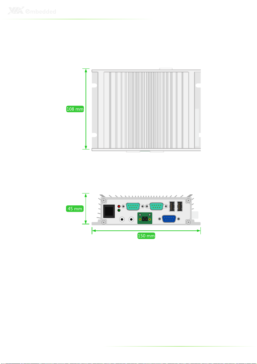
AMOS-3001 DIMENSIONS
6
Page 17
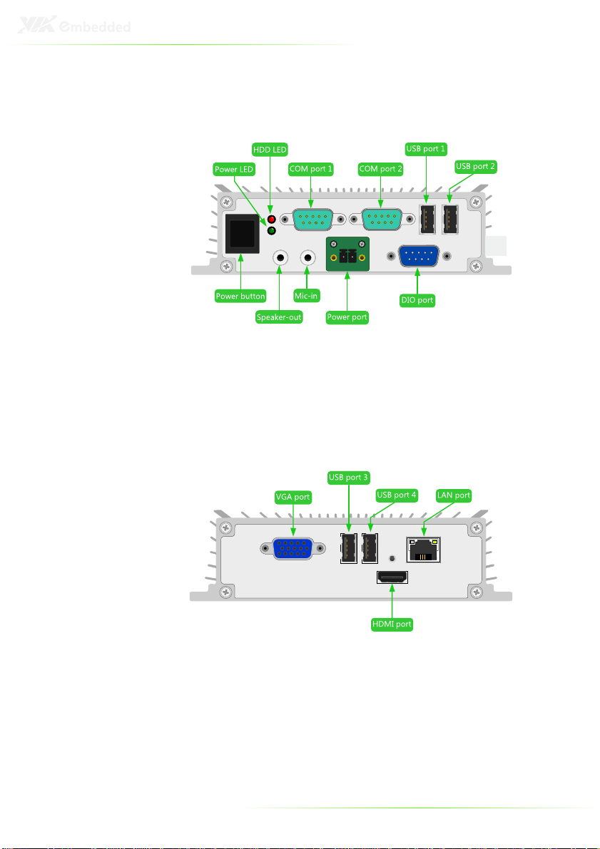
AMOS-3001 I/O LAYOUT (FRONT)
AMOS-3001 I/O LAYOUT (REAR)
7
Page 18
ACCESSORIES
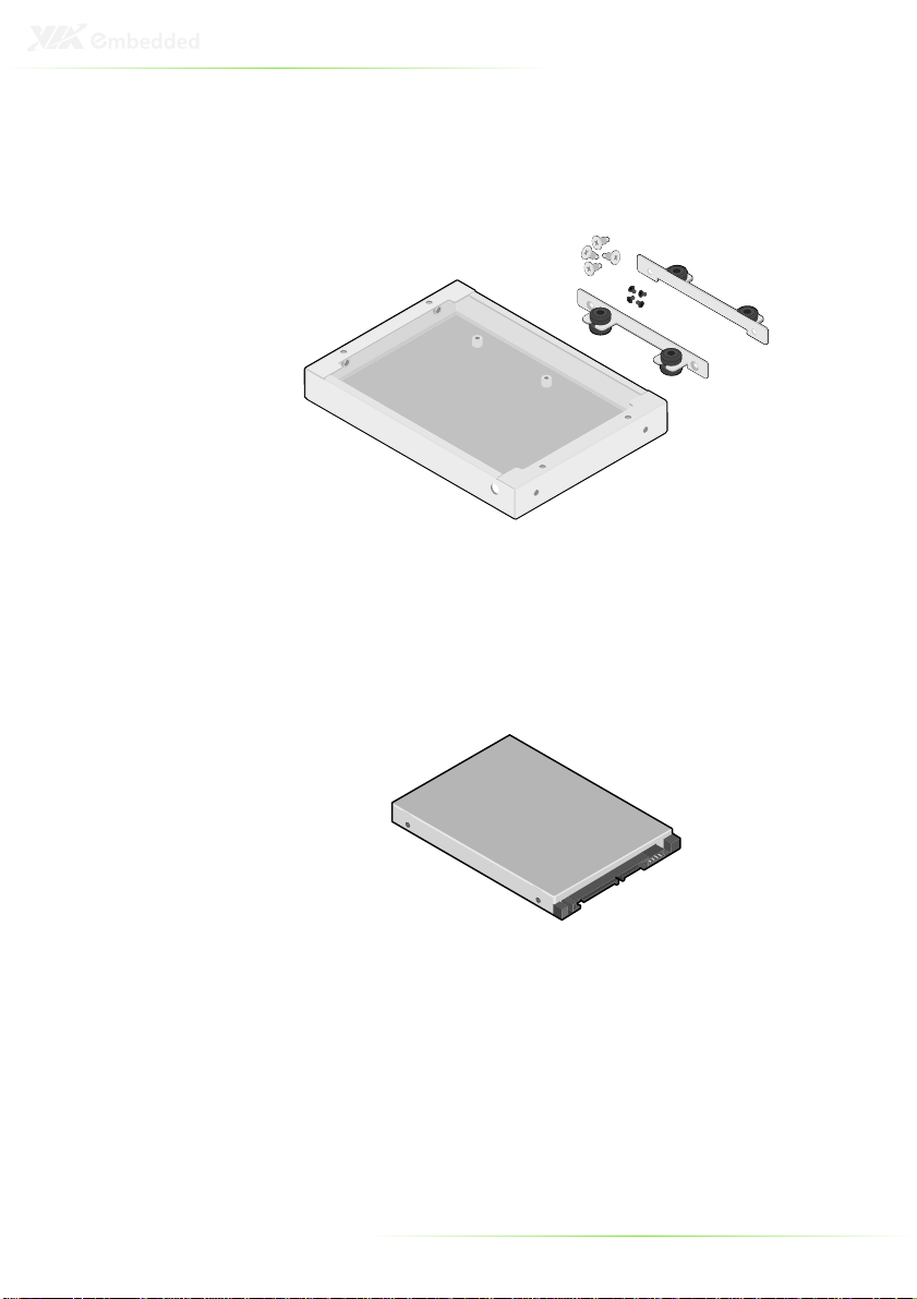
AMOS-3001 storage expansion kit
SATA 2.5” hard disk
8
Page 19
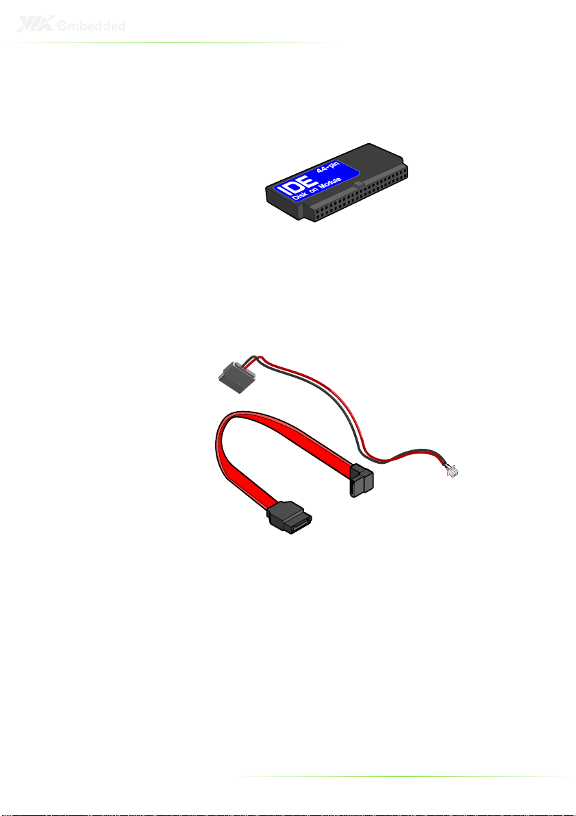
IDE Flash DOM
SATA hard disk cables
9
Page 20
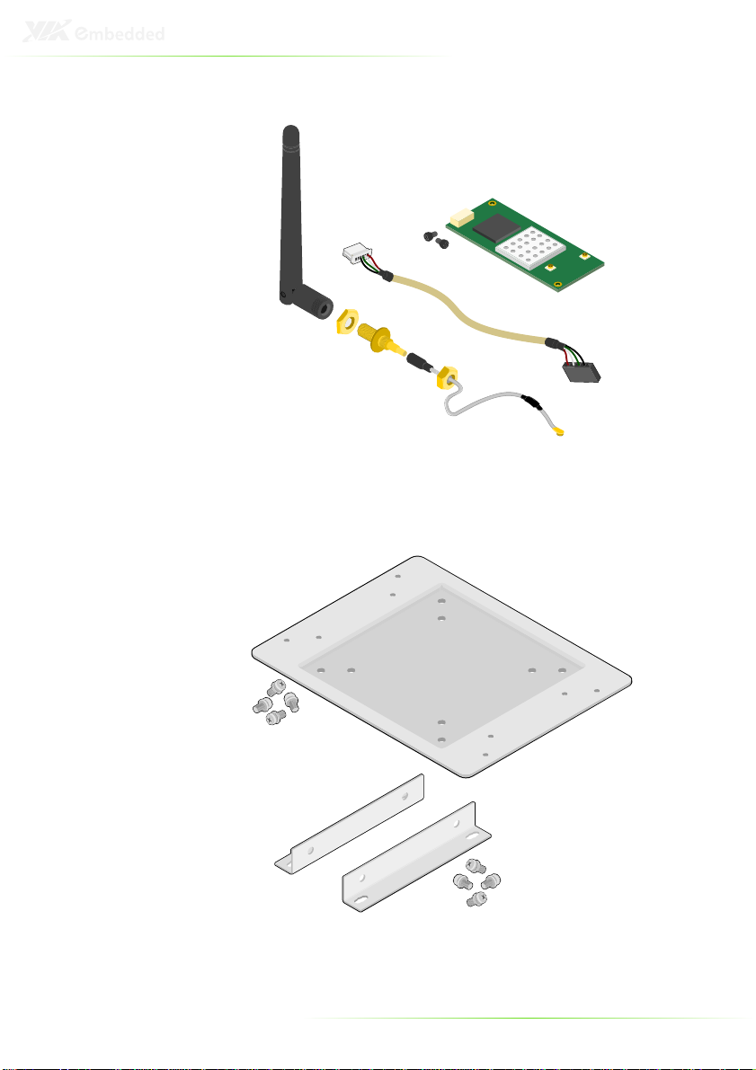
WLAN kit
VESA mounting kit
10
Page 21

2
Basic installation
11
Page 22
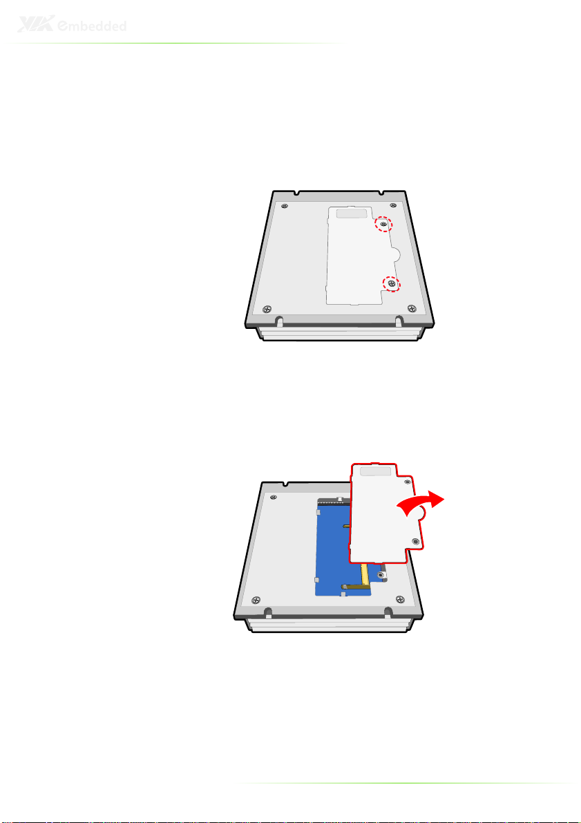
INSTALLING THE MEMORY
Step 1
Step 1
Step 1Step 1
Locate memory access cover on the bottom of the AMOS-3001
and remove the two screws as indicated in the figure below.
Step 2
Step 2
Step 2Step 2
Remove the memory access cover.
12
Page 23
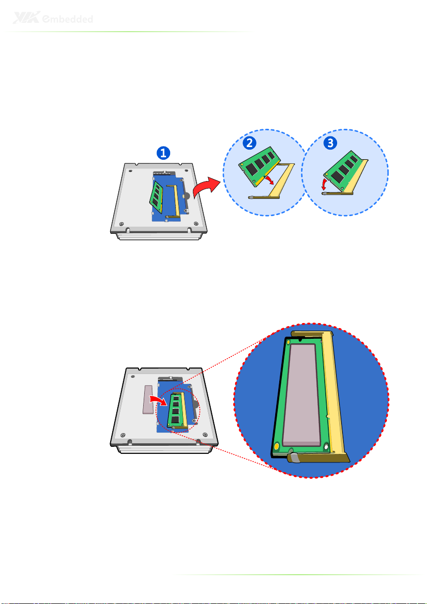
Step 3
Step 3
Step 3Step 3
Insert the memory module into the SODIMM socket at the 45
degree angle. Then push down until the memory module snaps
into place. The SODIMM socket has two locking mechanisms that
will click once the memory module has been fully inserted.
Step 4
Step 4
Step 4Step 4
Peel the protective layers off of the memory thermal pad. Then
apply the thermal pad on the memory module.
13
Page 24

Step 5
Step 5
Step 5Step 5
Reinstall the memory access cover. Secure the memory access
cover in place with the two screws.
14
Page 25
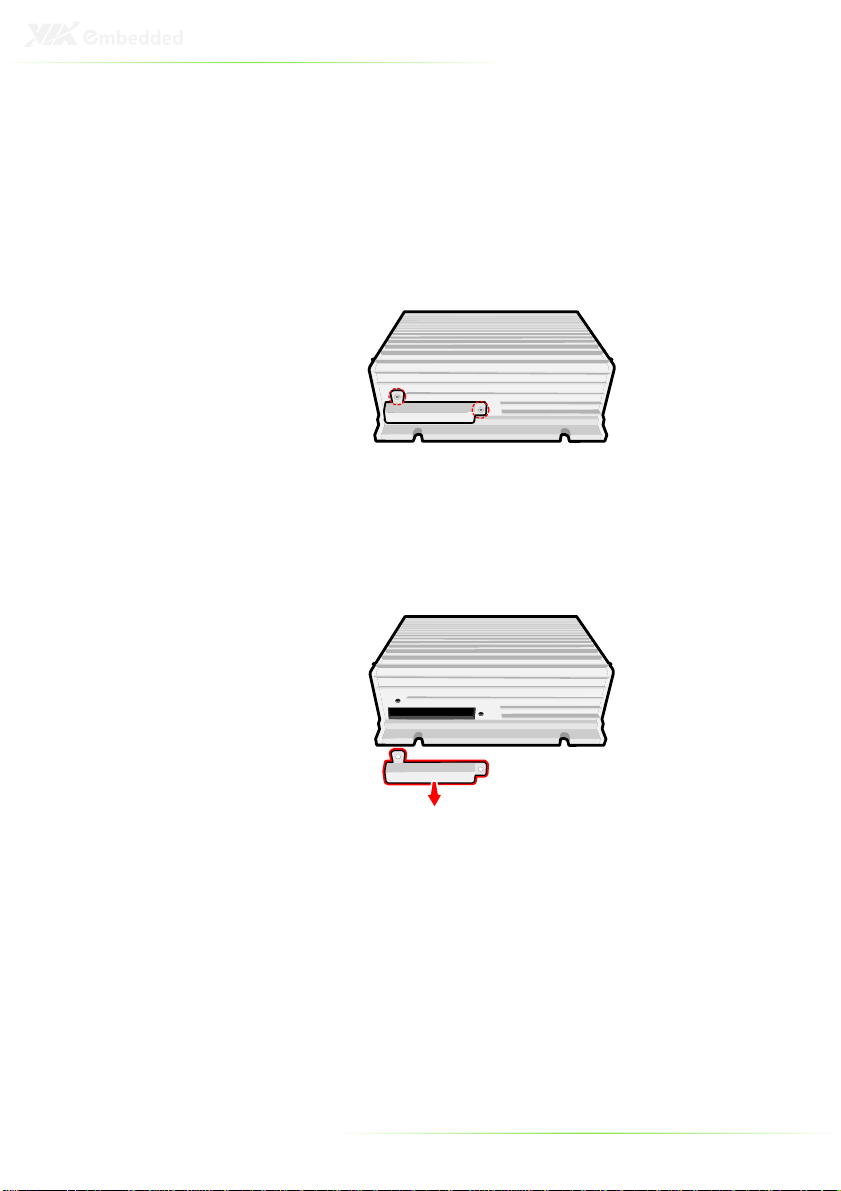
INSTALLING THE IDE FLASH DOM
Step 1
Step 1
Step 1Step 1
Locate the IDE Flash DOM access cover on the side of the AMOS3001 and remove the two screws as indicated in the figure below.
Step 2
Step 2
Step 2Step 2
Remove the IDE Flash DOM access cover.
15
Page 26
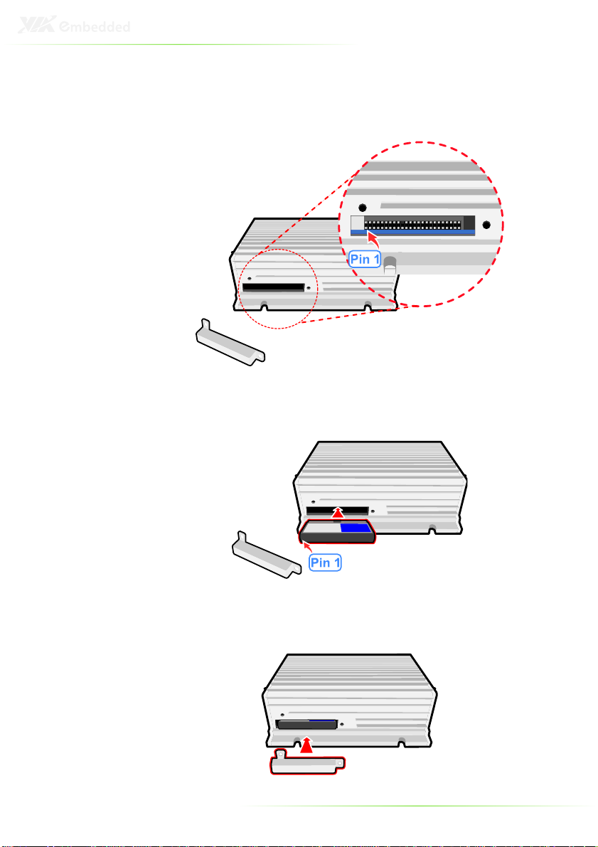
Step 3
Step 3
Step 3Step 3
Pin 1 of the IDE Flash DOM connector is on the left side of the
DOM access port. Ensure that the pins are correctly aligned with
the IDE Flash DOM before attempting to insert the IDE Flash DOM.
Step 4
Step 4
Step 4Step 4
Insert the IDE Flash DOM into the DOM access port. Ensure that
pin 1 is on the correct side before inserting.
Step 5
Step 5
Step 5Step 5
Replace the DOM access cover. Secure the DOM access cover
with the two screws.
16
Page 27

PREPARING CABLES AND CONNECTORS
Opening the Chassis
Step 1
Step 1
Step 1Step 1
Remove the four corner screws from the bottom of the AMOS-
3001.
Step
Step 2222
Step Step
Flip over the chassis and unscrew the four chassis screws from
both face plates including the screws of VGA port and HDMI®
port on rear plate.
17
Page 28

Step
Step 3333
Step Step
Then pull the rear face plate and gently slide the top cover
backward and lift off the top cover.
18
Page 29

Connecting the DIO Cable
Step 1
Step 1
Step 1Step 1
Locate the DIO pin header onto the EPIA-P720 mainboard.
Step 2
Step 2
Step 2Step 2
Then insert the DIO cable connector onto the pin header.
19
Page 30

Connecting the Audio Cable
Step 1
Step 1
Step 1Step 1
Locate the audio pin header on the P720-B daughterboard.
Step 2
Step 2
Step 2Step 2
Gently insert the audio cable onto the pin header.
20
Page 31

Connecting the Power Switch Cable
Step 1
Step 1
Step 1Step 1
Locate the power switch pin head on the EPIA-P720-B
daughterboard.
Step 2
Step 2
Step 2Step 2
Then gently insert the power switch cable onto the pin header.
The red wire should be on pin 1 of the pin header.
21
Page 32

Connecting the 10-pin UART Cable
Step 1
Step 1
Step 1Step 1
Locate the 10-pin UART connector ports on the P720-B
daughterboard and mainboard.
Step 2
Step 2
Step 2Step 2
Follow the proper orientation of the connector ports. Then gently
connect the UART cable to the daughterboard and the
mainboard.
22
Page 33

Connecting the 12-pin UART Cable
Step 1
Step 1
Step 1Step 1
Locate the 12-pin UART connector ports on the P720-B
daughterboard and mainboard.
Step 2
Step 2
Step 2Step 2
Follow the proper orientation of the connector ports. Then gently
connect the UART cable to the daughterboard and the
mainboard.
23
Page 34

Connecting the Power Cable
Step 1
Step 1
Step 1Step 1
Locate the power connector and then insert the power cable into
the connector.
24
Page 35

3
Installing the
expansion kit
25
Page 36

PREPARING THE AMOS-3001
Before installing the storage expansion kit, the AMOS-3001 needs
to be prepared.
Step 1
Step 1
Step 1Step 1
Remove the memory access cover.
Step 2
Step 2
Step 2Step 2
Remove the cable hole cover on the memory access cover. File
down any rough edges on the cable hole.
26
Page 37

Step
Step 3333
Step Step
Thread the required cables for the SATA storage device through
the cable hole. To install a SATA 2.5” hard disk, a SATA power
cable and a SATA data cable are required. If installing the WLAN
kit the WLAN USB cable also needs to be threaded through the
cable hole.
Step 4
Step 4
Step 4Step 4
Gently remove the rear face plate to remove the chassis top cover.
27
Page 38

Step 5
Step 5
Step 5Step 5
Carefully unscrew and remove the P720-B daughterboard. Lift the
board off vertically until it has been disconnected from all pins,
otherwise the pin header may be bent.
Step
Step 6666
Step Step
Wrap the SATA cable and SATA power cable into the available
space on the P720-B daughterboard.
28
Page 39

Step
Step 7777
Step Step
First insert the SATA data and SATA power cable through the
cable hole in the bottom plate. Ensure that the cable is placed in
the spacing on the daughterboard. Then gently insert the SATA
data and power cable onto the board connector.
29
Page 40

INSTALLING THE SATA 2.5” HARD DISK
Step 1
Step 1
Step 1Step 1
Remove the SATA 2.5” hard disk mounting bracket.
Step 2
Step 2
Step 2Step 2
Align the mounting holes on the SATA 2.5” hard disk with the
mounting holes on the hard disk mounting bracket.
30
Page 41

Step 3
Step 3
Step 3Step 3
Secure the hard disk in place with four hard disk screws. Then
connect the SATA power and data cables to the hard disk.
Step 4
Step 4
Step 4Step 4
Align the mounting bracket with the mounting holes on the
storage chassis. Secure the bracket in place with four screws.
31
Page 42

INSTALLING THE WLAN KIT
Step 1
Step 1
Step 1Step 1
Locate the WLAN antenna hole and install the WLAN antenna.
Step
Step 2222
Step Step
Mount the WLAN module on the bottom side of storage chassis
cover with two screws.
32
Page 43

Step
Step 3333
Step Step
Flip the cover plate over and connect the WLAN USB cable to the
mini USB connector on the WLAN module.
Step 4
Step 4
Step 4Step 4
Connect the WLAN antenna cable to the mini RF connector on
the WLAN module.
33
Page 44

Step 5
Step 5
Step 5Step 5
Locate the WLAN pin head on the P720-B daughterboard.
Step 6
Step 6
Step 6Step 6
First insert the WLAN cable through the cable hole in the bottom
plate of AMOS-3001 then gently connect the WLAN cable to the
WLAN pin header on the daughterboard.
Note:
When the WLAN cable is installed, USB port 5 will be disabled.
34
Page 45

MOUNTING THE STORAGE CHASSIS
Step 1
Step 1
Step 1Step 1
First remove the cover of the IDE Flash DOM slot. Then position
the AMOS-3001 directly above the storage chassis with the
bottom side facing down. Align the mounting holes of the
AMOS-3001 with those of the storage chassis.
35
Page 46

Step 2
Step 2
Step 2Step 2
Insert the storage chassis cover in between the AMOS-3001 and
storage chassis.
Step
Step 3333
Step Step
Secure first the storage chassis to the AMOS-3001 with four screws.
Then replace the IDE Flash DOM cover with two screws.
36
Page 47

INSTALLING THE MOUNTING PLATE
Step
Step 1111
Step Step
Fasten the VESA mounting plate to a VESA mountable device
with four screws.
Step 2
Step 2
Step 2Step 2
Position the mounting brackets on both sides of the storage
expansion kit with four screws.
37
Page 48

Step 3
Step 3
Step 3Step 3
Secure the mounting brackets to the VESA mounting plate with
four screws.
With Storage Chassis
With Storage Chassis
With Storage ChassisWith Storage Chassis
Without Storage Chassis
Without Storage Chassis
Without Storage ChassisWithout Storage Chassis
38
Page 49

4
BIOS Setup
This chapter gives a detailed explanation of the BIOS setup
functions.
39
Page 50

ENTERING THE BIOS SETUP MENU
Power on the computer and press <Delete
of the boot sequence to enter the BIOS setup menu. If you missed
the BIOS setup entry point, restart the system and try again.
Delete> during the beginning
DeleteDelete
CONTROL KEYS
Keys Description
Up Move to the previous item
Down Move to the next item
Left Move to the previous tab
Right Move to the next tab
Enter Select the item
Esc Jumps to the Exit menu or returns to the main menu
+ (number pad) Increase the numeric value
- (number pad) Decrease the numeric value
F1 General help, only for Status Page Setup Menu and
F7 Discard Changes
F9 Load Optimized defaults
F10 Save all the changes and exit
from a submenu
Option Page Setup Menu
40
Page 51

GETTING HELP
The BIOS setup program provides a “General Help
can display this screen from any menu/sub-menu by pressing
<F1
F1>. The help screen displays the keys for using and navigating
F1F1
the BIOS setup. Press <EEEEsc
sc> to exit the help screen.
scsc
General Help” screen. You
General HelpGeneral Help
41
Page 52

MAIN MENU
AMIBIOS
BIOS version number and related information.
Processor
CPU information.
System Memory
Memory size.
System Time
Use the key “+” or “-” to configure system time. The time format is
[Hour : Minute : Second].
System Date
Use the key “+” or “-” to configure system Date. The date format is
[Day, Month, Date, Year].
42
Page 53

ADVANCED SETTINGS
CPU Configuration
IDE Configuration
ACPI Configuration
APM Configuration
Spread Spectrum Configuration
USB Configuration
43
Page 54

CPU CONFIGURATION
CMPXCHG8B instruction support
Settings: [Enabled, Disabled]
44
Page 55

IDE CONFIGURATION
Parallel ATA IDE Controller
Settings: [Disabled, Primary]
Hard Disk Write Protect
Settings: [Disabled, Enabled]
IDE Detect Time Out (Sec)
Settings: [0, 5, 10, 15, 20, 25, 30, 35]
ATA(PI) 80Pin Cable Detection
Settings: [Host & Device, Host, Device]
45
Page 56

IDE DRIVES
PATA Device
SATA Device
Type
Settings: [Not Installed, Auto, CD/DVD, ARMD]
LBA/Large Mode
Settings: [Disabled, Auto]
46
Page 57

Block (Multi-Sector Transfer)
Settings: [Disabled, Auto]
PIO Mode
Settings: [Auto, 0, 1, 2, 3, 4]
DMA Mode
Settings: [Auto]
S.M.A.R.T.
Self Monitoring Analysis and Reporting Technology, a monitoring
system for hard disks.
Settings: [Auto, Disabled, Enabled]
32Bit Data Transfer
Settings: [Enabled, Disabled]
47
Page 58

ACPI SETTINGS
General ACPI Configuration
Advanced ACPI Configuration
Chipset ACPI Configuration
48
Page 59

GENERAL ACPI CONFIGURATION
Suspend Mode
Select the ACPI state used for system suspend.
Settings Description
S1(POS) S1/Power On Suspend (POS) is a low power state. In this
state, no system context (CPU or chipset) is lost and
hardware maintains all system contexts
S3(STR) S3/Suspend To RAM (STR) is a power-down state. In this
state, power is supplied only to essential components
such as main memory and wakeup-capable devices. The
system context is saved to main memory, and context is
restored from the memory when a "wakeup" event
occurs.
Auto Depends on the OS to select the state.
Repost Video on S3 Resume
To determine whether to invoke VGA BIOS post on S3/STR
resume or not.
Settings: [No, Yes]
49
Page 60

ADVANCED ACPI CONFIGURATION
ACPI Version Features
To enable RSDP pointers to 64-bit Fixed System Description Tables.
Settings: [ACPI v1.0, ACPI v2.0, ACPI v3.0]
ACPI APIC Support
To include ACPI APIC table pointer to RSDT pointer list.
Settings: [Enabled, Disabled]
AMI OEMB Table
To include OEMB table pointer to R(X)SDT pointer lists.
Settings: [Disabled, Enabled]
Headless Mode
To enable or disable headless operation mode through ACPI.
Settings: [Disabled, Enabled]
50
Page 61

CHIPSET ACPI CONFIGURATION
USB Device Wakeup Function
Settings: [Disabled, Enabled]
51
Page 62

APM CONFIGURATION
Power Management / APM
Settings: [Disabled, Enabled]
Power Button Mode
Settings: [On/Off, Standby, Suspend]
Suspend Power Saving Type
Settings: [C3, S1]
Restore on AC / Power Loss
The field defines how the system will respond after an AC power
loss during system operation.
Settings Description
Power Off Keeps the system in an off state until the power button is
Power On Restarts the system when the power is back
Last State Save in last state
pressed.
Manual Throttle Ratio
Settings: [0%-6.25%, 6.25%-12.5%, 18.75%-25%, 31.25%-37.5%,
37.5%-43.75%, 43.75%-50%, 50%-56.25%, 56.25%-62.5%, 62.5%-
68.75%, 68.75%-75%, 75%-87.5%, 75%-81.25%, 81.25%-87.5%,
87.5%-93.75%, 93.75%-100%]
52
Page 63

System Thermal
Settings: [Disabled, Enabled]
Standby Time Out
Settings: [Disabled, 1/2/4/8/10/20/30/40/50/60 minutes]
Suspend Time Out
Settings: [Disabled, 1/2/4/8/10/20/30/40/50/60 minutes]
Hard Disk Time Out (Minute)
Settings: [Disabled, 1/2/3/4/5/6/7/8/9/10/11/12/13/14/15
minutes]
Green PC Monitor Power State
Settings: [Standby, Suspend, Off]
Video Power Down Mode
Settings: [Disabled, Standby, Suspend]
Hard Disk Power Down Mode
Settings: [Disabled, Standby, Suspend]
Display Activity
Settings: [Ignore, Monitor]
Monitor IRQ3~15
Enables or disables the monitoring of the specified IRQ line.
Settings: [Ignore, Monitor]
Note:
IRQ (Interrupt Request) lines are system resources allocated to
I/O devices. When an I/O device needs to gain attention of the
operating system, it signals this by causing an IRQ to occur.
After receiving the signal, when the operating system is ready,
the system will interrupt itself and perform the service required
by the IO device.
53
Page 64

Resume On PME#
Settings: [Disabled, Enabled]
Resume On PS/2 KBC
Settings: [Disabled, S3, S3/S4/S5]
Wake-up Key
Settings: [Any Key, Specific Key]
Resume on PS/2 Mouse
Enable any mouse activity to restore the system from the power
saving mode to an active state.
Settings: [Disabled, S3, S3/S4/S5]
Resume on RTC Alarm
Set a scheduled time and/or date to automatically power on the
system.
Settings: [Disabled, Enabled]
54
Page 65

SPREAD SPECTRUM CONFIGURATION
Spread Spectrum Configuration
Settings: [Disabled, 0.1%, 0.2%, 0.3%, 0.4%, 0.5%, 0.6%, 0.7%, 0.8%,
0.9%]
55
Page 66

USB CONFIGURATION
USB 1.1 Ports Configuration
To enable USB 1.1 host controllers.
Settings: [Disabled, USB 2 ports, USB 4 ports, USB 6 ports]
USB 2.0 Ports Enable
To enable USB 2.0 host controllers.
Settings: [Disabled, Enabled]
USB Device Mode Enable
Settings: [Enabled, Disabled]
Legacy USB Support
To enable support for legacy USB.
Settings: [Disabled, Enabled, Auto]
USB 2.0 Controller Mode
To configure the USB 2.0 controller in HiSpeed (480Mbps) or
FullSpeed (12Mbps).
Settings: [FullSpeed, HiSpeed]
BIOS EHCI Hand-Off
Settings: [Disabled, Enabled]
56
Page 67

ADVANCED PCI/PNP SETTINGS
Note:
This section covers some very technical items and it is strongly
recommended to leave the default settings as it is unless you
are an experienced user.
Clear NVRAM
To clear NVRAM during system boot.
Settings: [No, Yes]
Plug & Play O/S
Settings: [No, Yes]
PCI Latency Timer
Value in units of PCI clocks for PCI device latency timer register.
Settings: [32, 64, 96, 128, 160, 192, 224, 248]
Allocate IRQ to PCI VGA
Settings: [Yes, No]
Palette Snooping
Settings: [Disabled, Enabled]
57
Page 68

PCI IDE BusMaster
Settings: [Disabled, Enabled]
Off Board PCI/ISA IDE Card
Settings: [Auto, PCI Slot1, PCI Slot2, PCI Slot3, PCI Slot4, PCI Slot5,
PCI Slot6]
IRQ3~15
Settings: [Available, Reserved]
DMA Channel 0
Settings: [Available, Reserved]
DMA Channel 1
Settings: [Available, Reserved]
DMA Channel 3
Settings: [Available, Reserved]
DMA Channel 5
Settings: [Available, Reserved]
DMA Channel 7
Settings: [Available, Reserved]
Reserved Memory Size
To decide the size of memory block to reserve for legacy ISA
devices.
Settings: [Disabled, 16k, 32k, 64k]
58
Page 69

BOOT SETTINGS
Boot Settings Configuration
Configuration settings during system boot.
Boot Device Priority
Specifies the boot device priority sequence.
59
Page 70

BOOT SETTINGS CONFIGURATION
Quick Boot
Settings: [Disabled, Enabled]
Display Logo
Settings: [Disabled, Enabled]
AddOn ROM Display Mode
Settings: [Force BIOS, Keep Current]
Bootup Num-Lock
To select power-on state for Num-Lock.
Settings: [Off, On]
PS/2 Mouse Support
Settings: [Disabled, Enabled, Auto]
Wait For ‘F1’ If Error
Settings: [Disabled, Enabled]
Hit ‘DEL’ Message Display
Settings: [Disabled, Enabled]
60
Page 71

Interrupt 19 Capture
Settings: [Disabled, Enabled]
61
Page 72

BOOT DEVICE PRIORITY
1st Boot Device
To specifies the boot sequence from the available devices. The
available boot devices are detected dynamically according to real
situation and variable options will be provided.
Settings: [Network: VIA Networking Bootagent, Disabled]
62
Page 73

SECURITY SETTINGS
Change Supervisor Password
This option is for setting a password for entering BIOS Setup.
When a password has been set, a password prompt will be
displayed whenever BIOS Setup is run. This prevents an
unauthorized person from changing any part of your system
configuration.
When a supervisor password is used, the BIOS Setup program can
be accessed and the BIOS settings can be changed.
Change User Password
When a user password is used, the BIOS Setup program can be
accessed but the BIOS settings cannot be changed.
Boot Sector Virus Protection
Settings: [Disabled, Enabled]
63
Page 74

ADVANCED CHIPSET SETTINGS
Caution:
The Advanced Chipset Features menu is used for optimizing the
chipset functions. Do not change these settings unless you are
familiar with the chipset.
North Bridge VIA VX855 Configuration
South Bridge VIA VX855 Configuration
64
Page 75

NORTH BRIDGE VIA VX855
CONFIGURATION
Software Reset E2 Issue
Settings: [Patch, Escape Patch]
Change DCLK using RDCKM
Settings: [Program, Escape Program]
Dynamic CKE
Settings: [Disabled, Enabled]
NB Performance Register
Settings: [Disabled, Enabled]
NB Energy Saving Register
Settings: [Disabled, Enabled]
65
Page 76

ONCHIP VGA CONFIGURATION
VGA Frame Buffer Size
Settings: [64MB, 128MB, 256MB]
CPU Direct Access Frame Buffer
Settings: [Disabled, Enabled]
Select Display Device
Settings: [CRT, HDMI, CRT+HDMI]
Panel Type
Settings: [02]
Dithering
Settings: [Disabled, Enabled]
66
Page 77

SOUTH BRIDGE VIA VX855
CONFIGURATION
High Definition Audio
Settings: [Disabled, Auto]
Enable Embedded COM
Settings: [Disabled, Enabled]
PCI SLOT1 Control (GigaLan)
Settings: [Disabled, Enabled]
PCI Delay Transaction
Settings: [Disabled, Enabled]
WATCH-DOG
Settings: [Disabled, Enabled]
67
Page 78

EXIT OPTIONS
Save Changes and Exit
Exit system setup after saving the changes, or press “F10”.
Discard Changes and Exit
Exit system setup without saving any changes, or press “Esc”.
Discard Changes
Discard changes which have been done so far to any of the setup
questions, or press “F7”.
Load Optimal Defaults
Load optimal default values for all the setup items, or press “F9”.
The default optimized values are set by the mainboard
manufacturer to provide a stable system with optimized
performance.
68
Page 79

A
Front & Rear Panel
IO Pin Descriptions
69
Page 80

IO PIN DESCRIPTION
Power Button
AMOS-3001 comes with an ATX supported
Power On/Off button, that support dual
function of Soft Power -On/Off, and Suspend.
Power Input (DC-In) Port
AMOS-3001 comes with a Phoenix connector.
Pin Signal
1 GND
2 +12V
LED Indicators (Power LED and HDD LED)
There are two LEDs on the front face
plate for indicating system status: The
Power LED is for power status and
flash in green color; and HDD LED is
for Flash Disk on Module (DOM) or
hard disk and compact flash disk status,
which flash in red color.
DIO Port
AMOS-3001 provides one D-sub 9-pin female connector, which
offers Digital IO communication interface port.
Pin Signal
1 GPIO1
2 GPI4
3 GPIO0
4 GPI5
5 GPO6
6 GPI9
7 GPO5
8 GPI8
9 +5V
70
Page 81

Audio Port (Speaker-out and Mic-in)
AMOS-3001 offers High Definition Audio ports by two jack
connectors Speaker-out and Mic-in.
Connector Type
Speaker-out Phone Jack 3.5Ø 5P, 90 Degree, Female, SHIELDED
Mic-in Phone Jack 3.5Ø 5P, 90 Degree, Female, SHIELDED
USB Ports
The AMOS-3001 provides four USB 2.0 ports; two in the front
panel, and two in the rear panel, which gives complete Plug &
Play and hot swapping external devices. The USB interface
complies with USB UHCI, Rev. 2.0 compliant. The USB interface
can be disabled in the system BIOS setup.
Pin Signal
1 VCC
2 USB_P03 USB_P0+
4 GND
COM Ports
The AMOS-3001 provides two D-Sub 9-pin connector as COM
port 1 and COM port 2 serial communications.
Pin
RS
RS----232
232 RS
RSRS
1 -DCDA -TX -TX
2 RXDA TX TX
3 TXDA RX 4 -DTRA -RX 5 GND GND GND
6 -DSRA - 7 -RTSA - 8 -CTSA - 9 -RIA - -
232232
COM Port
COM Port 1
COM PortCOM Port
1
1 1
The COM port 1 offers one standard RS-232 serial communication
interface.
Signal
RS----422
422 RS
RSRS
422422
RS----485
485
RSRS
485485
71
Page 82

COM Port 2
COM Port 2
COM Port 2COM Port 2
The COM port 2 can be configured to operate in RS-232, RS-422
or RS-485 serial communication interface by setting up the selector
switch (SW1). To select the RS-232/422/485 setting, remove the
top cover chassis of AMOS-3001 to locate the selector switch on
the P720-B daughterboard.
The setting instruction to select RS-232/422/485 mode, please
refer to the table below.
SW1
SW1 1111 2222 3333 4444
SW1SW1
RS
RS----232
232 On On Off Off
RSRS
232232
RS
RS----422
422 Off Off On Off
RSRS
422422
RS
RS----485
485 Off Off Off On
RSRS
485485
VGA Port
The AMOS-3001 provides a high resolution VGA interface by a 15pin D-sub female connector to support a VGA CRT monitor. It
supports VGA and VESA, up to 1920 x 1200 @ 60Hz resolution
and up to 512 MB shared memory.
Pin Signal
1 Red
2 Green
3 Blue
4 NC
5 GND
6 GND
7 GND
8 GND
9 NC
10 GND
11 NC
12 DDC DAT
13 H-SYNC
14 V-SYNC
15 DDC CLK
72
Page 83

HDMI® Port
The AMOS-3001 provides High Definition Multimedia Interface
port for connecting to high definition video and digital audio. The
HDMI® port connector allows you to connect digital video devices
which utilize a high definition video signal.
Pin Signal Pin Signal
1 TX2+ 2 GND
3 TX2- 4 TX1+
5 GND 6 TX17 TX0+ 8 GND
9 TX0- 10 TXC+
11 GND 12 TXC13 - 14 15 DDCSCL 16 DDCSDA
17 GND 18 +5V
19 Hot Plug Detect
LAN Port
The AMOS-3001 is equipped with VIA VT6122 Gigabit LAN
controller. The Ethernet port provides a standard RJ-45 jack
connector with LED indicators to show its Active/Link status
(Green LED) and Speed status (white LED).
Pin Signal
1 TXPA
2 TXNA
3 TXPB
4 TXNB
5 TXPC
6 TXNC
7 TXPD
8 TXND
73
Page 84

Taiwan Headquarters
1F, 531 Zhong-zheng Road,
Xindian District, New Taipei City 231,
Taiwan
TEL: 886.2.2218.5452
FAX: 886.2.2218.5453
Email: embedded@via.com.tw
China
Tsinghua Science Park Bldg. 7
No. 1 Zongguancun East Road
Haiden District, Beijing 100084
TEL: 86.10.59852288
FAX: 86.10.59852299
Email: embedded@viatech.com.cn
USA
940 Mission Court
Fremont, CA 94539
USA
TEL: 1.510.683.3300
FAX: 1.510.687.4654
Email: embedded@viatech.com
Japan
3-15-7 Ebisu MT Bldg. 6F
Higashi, Shibuya-ku
Tokyo 150-0011
TEL: 81.3.5466.1637
FAX: 81.3.5466.1638
Email: embedded@viatech.co.jp
Europe
In den Dauen 6
53117 Bonn
Germany
TEL: 49.228.688565.0
FAX: 49.228.688565.19
Email: embedded@via-tech.de
Korea
2F, Sangjin Bldg., 417
Dogok-Dong, Gangnam-Gu
Seoul 135-854
TEL: 82.2.571.2986
FAX: 82.2.571.2987
Email: embedded@via-korea.com
74
 Loading...