

Page 1

Mobile
Broadband
Router
VMBR-1520
Installation,
Operation, and
Maintenance Guide
ViaSat Document Number
1075152
(Rev. 001)
ViaSat, Inc.
6155 El Camino Real
Carlsbad, CA 92009-1699
Tel: (760) 476-2200
Fax: (760) 929-3941
www.viasat.com
Page 2

Page 3

Mobile Broadband Router, VMBR-1520
Installation, Operation, and Maintenance Guide
Page 4

Page 5

DRAFT
Mobile
Broadband
Router
VMBR-1520
Installation,
Operation, and
Maintenance Guide
ViaSat Document Number
1075152
(Rev. 001)
ViaSat, Inc.
6155 El Camino Real
Carlsbad, CA 92009-1699
Tel: (760) 476-2200
Fax: (760) 929-3941
www.viasat.com
Page 6

Page 7

Publication Information
ViaSat, Inc.
Corporate
Headquarters
6155 El Camino Real
Carlsbad, CA 92009-1699
Phone: (760) 476-2200
Fax: (760) 929-3941
Germantown, MD
20511 Seneca Meadows
Parkway Suite 200
Germantown, MD 20876
Phone: (240) 686-4400
Fax: (240) 686-4800
Duluth, GA
1725 Breckinridge Plaza
Duluth, GA 30096
Phone: (678) 924-2400
Fax: (678) 924-2480
www.viasat.com
VMBR-1520 Mobile Broadband Router Installation, Operation, and Maintenance Guide
Revision Number Date Released Comments
001 September 25, 2008 Initial draft
© 2008 ViaSat, Incorporated. All rights reserved.
ViaSat® and the ViaSat logo are registered trademarks of ViaSat, Inc.
ArcLightTM is a trademark of ViaSat, Inc.
Other product names included in this document are trademarks of their
respective owners.
ViaSat Proprietary—The information, specifications, and features
contained in this document are subject to change without notice and
should not be construed as a commitment by ViaSat, Inc.
ViaSat, Inc. assumes no responsibility for any errors that may appear in
this document nor does it make expressed or implied warranty of any kind
with regard to this material, including, but not limited to, the implied
warranties of merchantability and fitness for a particular purpose. ViaSat,
Inc. shall not be liable for incidental or consequential damages in
conjunction with, or arising out of the furnishing, performance, or use of
this document and the program material it describes.
Rev. 001 1075152
i
Page 8

VMBR-1520 Mobile Broadband Router Installation, Operation and Maintenance Guide
ii
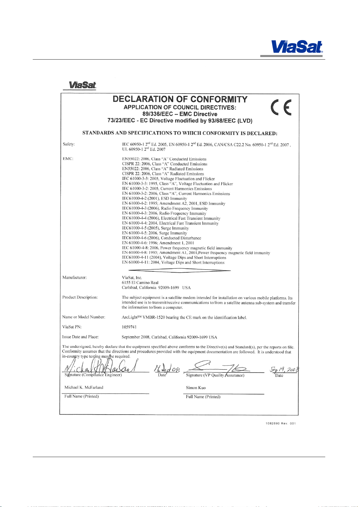
REGULATORY COMPLIANCE and NOTICES
FCC Notice
This device complies with part 15 of the FCC Rules. Operation is subject to the following two conditions:
1. This device may not cause harmful interference, and
2. This device must accept any interference received, including interference that may cause undesired operation.
NOTE: This equipment has been tested and found to comply with the limits for a Class TBD) digital device, pursuant to Part 15 of the
FCC Rules. These limits are designed to provide reasonable protection against harmful interference in a residential installation. This
equipment generates, uses, and can radiate radio frequency energy and, if not installed and used in accordance with the instructions, may
cause harmful interference to radio communications. However, there is no guarantee that interference will not occur in a particular
installation. If this equipment does cause harmful interference to radio or television reception, which can be determined by turning the
equipment off and on, the user is encouraged to try to correct the interference by one or more of the following measures:
-- Reorient or relocate the receiving antenna.
-- Increase the separation between the equipment and receiver.
-- Connect the equipment into an outlet on a circuit different from that to which the receiver is connected.
-- Consult the dealer or an experienced radio/TV technician for help.
CAUTION: Shielded I/O cables must be used and all covers must be in place when operating this equipment.
Canadian Department of Communications compliance statement:
This equipment does not exceed Class A limits per radio noise emissions for digital apparatus set out in the Radio Interference
Regulation of the Canadian Department of Communications. Operation in a residential area may cause unacceptable interference to radio
and TV reception requiring the owner or operator to take whatever steps are necessary to correct the interference.
Avis de conformite aux normes du ministere des Communications du Canada:
Cet equipment ne dépasse pas les limites de Class A d’émission de bruits radioélectriques pour les appareils numériques tels que
prescrites par le Règlement sur le brouillage radioélectrique etabli par le ministére de Communications du Canada. L’exploitation faite en
milieu résidentiel peut entrainer le brouillage des réceptions radio et télé, ce qui obligerait le propriétaire ou l’operateur à prendre les
dispositions nécessaires pour en éliminer les causes.
Electro-Magnetic Emissions Compliance
The equipment has been tested for compliance with the following emissions and immunity requirements:
Emissions:
FCC 15B, Sec. 107, Class “A” Conducted Emissions
FCC 15B, Sec. 109, Class “A” Radiated Emissions
EN 55022: 2006, Class “A” Conducted Emissions
EN 55022: 2006, Class “A” Radiated Emissions
CISPR 22: 2006, Class “A” Conducted Emissions
CISPR 22: 2006, Class “A” Radiated Emissions
EMC:
EN 55024:1998, Amendment A2: 2003
IEC 61000-4-2: 2001, EN 61000-4-2: 1995; Amendment A2, 2001 ESD Immunity
IEC 61000-4-3: 2006, EN 61000-4-3: 2006 Radio Frequency Immunity
IEC 61000-4-4: 2006, EN 61000-4-4: 2004 Electrical Fast Transient Immunity
IEC 61000-4-5: 2005, EN 61000-4-5: 2006 Surge Immunity
IEC 61000-4-6: 2006, EN 61000-4-6: 1996; Amendment 1, 2001 RF Common Mode Immunity
IEC 61000-4-8: 2006, EN 61000-4-8: 1993; Amendment A1, 2001 Power frequency magnetic field immunity
IEC 61000-4-11: 2004, EN 61000-4-11: 2004 Voltage Dips and Short Interruptions
IEC 61000-3-3: 2005, EN 61000-3-3: 1995, Class “A” Voltage Flucuation and Flicker
IEC 61000-3-2: 2005, EN 61000-3-2: 2006, Class “A” Current Harmonics Emissions
Immunity characteristics — Limits and methods of
measurement, Amendment A2:2003 to EN 55024:1998
1075152 Rev. 001
Page 9

VMBR-1520 Mobile Broadband Router Installation, Operation, and Maintenance Guide
Safety Compliance
The equipment has been tested and is in compliance with the following safety requirements:
IEC 60950-1 2nd Ed. 2005
EN 60950-1 2nd Ed. 2006
UL 60950-1 2nd Ed. 2007
CAN/CSA-C22.2 No. 60950-1 2nd Ed. 2007
Rev. 001 1075152
iii
Page 10
VMBR-1520 Mobile Broadband Router Installation, Operation and Maintenance Guide
iv
1075152 Rev. 001
Page 11

VMBR-1520 Mobile Broadband Router Installation, Operation, and Maintenance Guide
Warnings, Cautions, and Notes
Safety precautions or important information found in this document
will normally be presented just prior to the point where the hazard is
likely to be encountered. Symbols used to identify the information are
defined as follows:
Warning
This symbol indicates a procedure or practice that, if not correctly
followed, could result in injury, death, or long term health hazard.
Caution
This symbol indicates a procedure or practices that, if not correctly
followed, could result in equipment damage, destruction, or make the
equipment not operate properly.
Caution
This symbol indicates that electrostatic discharge (ESD) precautions
must be observed or the equipment may be damaged.
Note
This symbol indicates information that is important to observe.
General Safety Precautions
General safety precautions are as follows:
Warning There are no user-serviceable parts inside any of the
equipment in your system. There are potentially lethal voltages inside the
equipment. It should only be opened by a technician trained and certified to
service ViaSat
products.
®
Warning
Installation of this product should be performed only by a
professional, certified installer.
Rev. 001 1075152
v
Page 12

VMBR-1520 Mobile Broadband Router Installation, Operation and Maintenance Guide
vi
Convention
Example
Explanation
screen display
Wed May 6 17:01:03 2000
This font indicates system output.
Conventions
This document uses the following conventions as listed below.
Terminology conventions used in this manual include:
Window – refers to screens that can be minimized and recalled from the
program control bar at the bottom of the monitor display.
Tab screens – refers to displays presented from clicking tabs on a main
screen.
Screens – refers to all other displays presented from clicking on
continuation buttons.
Pop-ups – refers to displays presented automatically based on some
action the user has taken, such as confirmation questions, information
confirmations, or error messages.
Tool-tips – refers to descriptive messages displayed by placing the
cursor on an editable field.
1075152 Rev. 001
Page 13

About This Manual
VMBR-1520 Mobile Broadband Router Installation, Operation, and Maintenance Guide
This manual contains information about the VMBR-1520 Mobile
Broadband Router including a general description, preparation for use,
installation, initial set up and configuration, configuration menu
reference, maintenance instructions, and preparation for reshipment.
Appendixes provide a site parameter value table (to be completed before
installation) used for initial configuration, an installation checklist,
software upgrade download procedures, and a list of definitions,
acronyms, and terms.
The following subjects are not covered in this manual:
• Network design is beyond the scope of this manual. The end
user is responsible for the design and administration of the
end-user network.
• Site Preparation is not covered. The installer is responsible
for preparing the site for proper installation of the product.
• Antenna Control Unit (ACU) and Antenna Subsystem (AS)
are not covered. Please refer to the ACU & AS
documentation.
Obtaining Additional Publications and Information
Additional publications and information including user guides, white
papers, application notes, release notes, software updates, training
schedules, and other technical information may be found on the
ViaSat® Extranet web site. The Extranet may be accessed through the
ViaSat® web site located at this URL:
http://extranet.viasat.com/
Customers and ViaSat® employees may apply for password access to
the Extranet by clicking on the Customer Login link and following the
link to create a new account.
Rev. 001 1075152
vii
Page 14

VMBR-1520 Mobile Broadband Router Installation, Operation and Maintenance Guide
viii
1075152 Rev. 001
Page 15

Table of Contents
VMBR-1520 Mobile Broadband Router Installation, Operation, and Maintenance Guide
1. GENERAL DESCRIPTION.............................................................................................................................................. 1-1
1.1 S
1.2 S
1.3 E
1.4 VMBR-1520 M
2. PREPARATION FOR USE AND INSTALLATION.................................................................................................... 2-9
2.1 I
2.2 T
2.3 H
3. INITIAL SET UP AND CONFIGURATION ................................................................................................................. 3-1
3.1 I
3.2 P
3.3 I
3.4 M
4. OPERATING PROCEDURES ....................................................................................................................................... 4-14
ECTION OVERVIEW
ATELLITE NETWORK
QUIPMENT LIST
1.4.1 VMBR-1520 Mobile Broadband Router Description ........................................................................................ 1-6
1.4.2 VMBR-1520 Front Panel Controls and Indicators ............................................................................................. 1-8
NTRODUCTION
OOLS AND TEST EQUIPMENT
ARDWARE INSTALLATION
2.3.1 Equipment Location ........................................................................................................................................... 2-10
2.3.2 Mounting ............................................................................................................................................................. 2-11
2.3.3 VMBR-1520 Connections and Descriptions..................................................................................................... 2-13
2.3.3.1 Coaxial Connections ...........................................................................................................................................2-14
2.3.3.2 ACU Connections ...............................................................................................................................................2-14
2.3.3.3 Console Connections ..........................................................................................................................................2-15
2.3.3.4 User Data Connections........................................................................................................................................2-15
2.3.3.5 ACU Data Connections .......................................................................................................................................2-16
2.3.3.6 BUC Power Connections ....................................................................................................................................2-16
2.3.3.7 Input Power ........................................................................................................................................................2-16
2.3.4 Additional Equipment ........................................................................................................................................ 2-16
NTRODUCTION
3.1.1 Quick Gui de and Summary .................................................................................................................................. 3-1
REPARATION FOR INITIAL SETUP
3.2.1 Parameters Required Before Configuring the VMBR-1520 .............................................................................. 3-2
3.2.2 Other Requirements Before Configuring the VMBR-1520 ............................................................................... 3-2
NITIAL SETUP AND CHECKOUT
3.3.1 Power On ............................................................................................................................................................... 3-3
3.3.2 Verify Operational Status ..................................................................................................................................... 3-3
3.3.2.1 Ping the Modem .................................................................................................................................................. 3-4
3.3.2.2 Verify Satellite Ac quisition Status ........................................................................................................................ 3-5
3.3.2.3 Ping the Hub Test Server ..................................................................................................................................... 3-6
3.3.2.4 Connect to the Hub Test Web Page ...................................................................................................................... 3-7
3.3.3 Normal Operation ................................................................................................................................................. 3-8
3.3.3.1 Verify Subscription Status.................................................................................................................................... 3-8
3.3.3.2 Verify Connection to the Internet ......................................................................................................................... 3-8
ODEM RECONFIGURATION
3.4.1 Preparation ............................................................................................................................................................ 3-9
3.4.2 Reconfiguration Details........................................................................................................................................ 3-9
3.4.2.1 General Parameters Menu .................................................................................................................................... 3-9
3.4.2.2 Satellite Parameters Menu ...................................................................................................................................3-10
3.4.2.3 ACU Parameters Menu .......................................................................................................................................3-10
3.4.2.4 Forward Link Parameters Menu ..........................................................................................................................3-11
3.4.2.5 Return Link Parameters Menu .............................................................................................................................3-11
3.4.2.6 Network Link Parameters Menu ..........................................................................................................................3-12
3.4.2.7 SCPS Parameters Menu ......................................................................................................................................3-12
3.4.2.8 Miscellaneous Parameters Menu .........................................................................................................................3-12
3.4.2.9 Calibration Paremeters ........................................................................................................................................3-13
3.4.3 Post Reconfiguration Reboot ............................................................................................................................. 3-13
...................................................................................................................................................... 1-1
.................................................................................................................................................... 1-1
............................................................................................................................................................ 1-2
OBILE BROADBAND ROUTER OVERVIEW
............................................................................................................................................................... 2-9
....................................................................................................................................... 2-9
......................................................................................................................................... 2-10
............................................................................................................................................................... 3-1
................................................................................................................................ 3-2
.................................................................................................................................... 3-3
......................................................................................................................................... 3-9
........................................................................................... 1-3
4.1 I
4.2 R
Rev. 001 1075152
NTRODUCTION
EBOOTING THE MODEM
............................................................................................................................................................. 4-14
............................................................................................................................................. 4-14
ix
Page 16

VMBR-1520 Mobile Broadband Router Installation, Operation and Maintenance Guide
x
4.3 A
4.4 C
4.5 C
4.6 C
5. VMBR-1520 CONFIGURATION MENU REFERENCE ............................................................................................ 5-1
5.1 I
5.2 VMBR-1520 .................................................................................................................................................................. 5-1
6. MAINTENANCE INSTRUCTIONS ............................................................................................................................. 6-13
6.1 I
6.2 S
6.3 I
6.4 C
6.5 G
6.6 E
6.7 R
7. RESHIPMENT .................................................................................................................................................................... 7-1
DJUSTING RETURN LINK POWER
HECKING FORWARD LINK STATE AND ACTIVITY
HECKING
HECKING
NTRODUCTION
5.2.1 Main Menu ............................................................................................................................................................ 5-2
5.2.1.1 General Parameters Menu .................................................................................................................................... 5-2
5.2.1.2 Satellite Parameters Menu .................................................................................................................................... 5-3
5.2.1.3 ACU Parameters Menu ........................................................................................................................................ 5-3
5.2.1.4 Forward Link Parameters Menu ........................................................................................................................... 5-4
5.2.1.5 Return Link Parameters Menu .............................................................................................................................. 5-4
5.2.1.6 Network Link Parameters Menu ........................................................................................................................... 5-5
5.2.1.7 SCPS Parameters Menu ....................................................................................................................................... 5-5
5.2.1.8 Miscellaneous Parameters Menu .......................................................................................................................... 5-6
5.2.1.9 Calibration Parameters Menu ............................................................................................................................... 5-6
5.2.1.10
5.2.2 System Status Menu ............................................................................................................................................. 5-7
5.2.3 ACU Status Menu ............................................................................................................................................... 5-10
5.2.4 Upgrade Terminal Software Menu .................................................................................................................... 5-11
5.2.5 Version Information Menu................................................................................................................................. 5-12
5.2.6 Exit Program Menu ............................................................................................................................................ 5-12
NTRODUCTION
PECIAL TOOLS AND TEST EQUIPMENT
NSPECTION
6.3.1 Chassis Inspection .............................................................................................................................................. 6-13
6.3.2 Inspection of Cable Assemblies and Connectors.............................................................................................. 6-14
LEANING
6.4.1 Cleaning the Chassis........................................................................................................................................... 6-14
6.4.2 Cleaning Connectors........................................................................................................................................... 6-14
ENERAL TROUBLESHOO TING
QUIPMENT TROUBLE SHOOTING
6.6.1 Power On Indicator Does Not Light .................................................................................................................. 6-16
6.6.2 Cannot Ping Modem ........................................................................................................................................... 6-17
6.6.3 Modem Cannot Acquire Satellite Link ............................................................................................................. 6-17
6.6.4 Cannot Ping Hub Test Server............................................................................................................................. 6-17
6.6.5 Cannot Connect to Hub Test Web Server ......................................................................................................... 6-17
6.6.6 Cannot Connect to the Internet .......................................................................................................................... 6-17
6.6.7 Front Panel Fault Indicator Lit or Flashing ....................................................................................................... 6-17
EMOVAL AND REPLACEMENT
6.7.1 Removing the Chassis ........................................................................................................................................ 6-18
6.7.2 Replacing the Chassis ......................................................................................................................................... 6-18
6.7.3 Removing and Replacing Cables and Connectors ............................................................................................ 6-18
ACU S
TATE
............................................................................................................................................... 4-17
NMS S
TATE
............................................................................................................................................... 4-18
............................................................................................................................................................... 5-1
Overhead Parameters Menu ............................................................................................................................. 5-6
............................................................................................................................................................. 6-13
.................................................................................................................................................................. 6-13
.................................................................................................................................................................... 6-14
.............................................................................................................................. 4-15
.................................................................................................... 4-16
...................................................................................................................... 6-13
.................................................................................................................................... 6-15
................................................................................................................................ 6-15
................................................................................................................................... 6-18
7.1 R
7.2 P
7.3 S
A
A
A
A
1075152 Rev. 001
ETURN TO THE FAC TORY
ACKAGING
HIPPING
PPENDIX
PPENDIX
PPENDIX
PPENDIX
......................................................................................................................................................................... 7-2
A VMBR-1520 I
B
C
D G
............................................................................................................................................. 7-1
.................................................................................................................................................................... 7-2
NITIAL SETUP PREPARATION CHECKLIST
I
NSTALLATION CHECKL IST
D
OWNLOADING SOFTWARE UPGRADES TO THE
LOSSARY
.................................................................................................................................................... D-1
.......................................................................................................................... B-1
........................................................................... A-1
VMBR-1520 .................................................................. C-1
Page 17

List of Figures
VMBR-1520 Mobil e Broadband Router Installation, Operation, and Maintenance Guide
Figure 1-1. Typical VSAT Network ............................................................................................................................................ 1-1
Figure 1-2. VMBR-1520 Mobile Broadband Router ................................................................................................................. 1-3
Figure 1-3. VMBR-1520 Functional Block Diagram................................................................................................................. 1-6
Figure 1-4. VMBR-1520 Front Panel.......................................................................................................................................... 1-8
Figure 2-1. VMBR-1520 Initial Basic Connections ................................................................................................................. 2-10
Figure 2-2. VMBR-1520 Chassis Dimension and Mounting Features ................................................................................... 2-12
Figure 2-3. VMBR-1520 Rear Panel ......................................................................................................................................... 2-13
Figure 3-1. Ping the VMBR-1520 ............................................................................................................................................... 3-4
Figure 3-2. VMBR-1520 System Status Web Page ................................................................................................................... 3-5
Figure 3-3. Ping the Hub Test Server .......................................................................................................................................... 3-6
Figure 3-4. Sample Hub Test Web Page ..................................................................................................................................... 3-7
Figure 6-1. Troubleshooting Flowchart - Power On Indicator Does Not Light ..................................................................... 6-16
Figure 7-1. Obtain Support PC IP Address for Softw are Update ............................................................................................. C-2
Rev. 001 1075152
xi
Page 18

VMBR-1520 Mobile Broadband Router Installation, Operation and Maintenance Guide
xii
List of Tables
Table 1-1. Furnished and Installer Supplied Items ..................................................................................................................... 1-2
Table 1-2. VMBR-1520 Mobile Broadband Router Specifications .......................................................................................... 1-4
Table 1-3. VMBR-1520 Front Panel Controls and Indicators ................................................................................................... 1-8
Table 2-1. Recommended Installation Tools and Test Equipment ........................................................................................... 2-9
Table 2-2. Rear Panel Connections and Components .............................................................................................................. 2-13
Table 2-3. ACU Port (J4) Pin Descriptions .............................................................................................................................. 2-14
Table 2-4. Console Port (J5) Pin Descriptions.......................................................................................................................... 2-15
Table 2-5. USER ENET Port (J8) Pin Descriptions ................................................................................................................. 2-15
Table 2-6. ACU ENET Port (J7) Pin Descriptions................................................................................................................... 2-16
Table 3-1. VMBR-1520 Set Up Quick Guide and Summar y .................................................................................................... 3-1
Table 5-1. VMBR-1520 Configuration Menu Cross Reference ................................................................................................ 5-1
Table 5-2. VMBR-1520 System Status Screen Definitions....................................................................................................... 5-8
Table 5-3. VMBR-1520 ACU Status Screen Definitions ........................................................................................................ 5-10
Table 5-4. VMBR-1520 Version Information Screen Definitions .......................................................................................... 5-12
Table 6-1. VMBR-1520 Maintenance Requirements Summary ............................................................................................. 6-13
Table 6-2. Special Tools and Test Equipment .......................................................................................................................... 6-13
Table 6-3. Fault Symptoms and Cross Reference .................................................................................................................... 6-15
1075152 Rev. 001
Page 19
1-1
1. General Description
1.1 Section Overview
This section contains information about the VMBR-1520 (ViaSat)
Mobile Broadband Router, including a description of the Satellite
Network, an equipment list, and a description of the components
contained in the VMBR-1520.
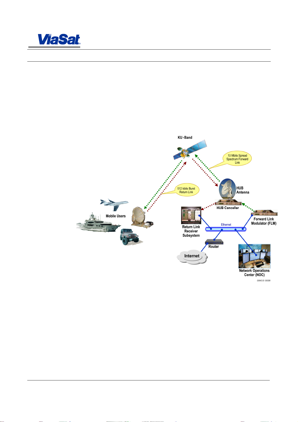
1.2 Satellite Network
The VMBR-1520 is designed for use in the ArcLightTM Internet Protocol
(IP) based STAR topology Very Small Aperture Terminal (VSAT) network
as shown in Figure 1-1.
VMBR-1520 Mobil e Broadband Router Installation, Operation, and Maintenance Guide
General Description
Figure 1-1. Typical VSAT Network
The STAR network consists of a broadband spread spectrum Forward
Link (FL) transmission from a central hub to the Mobile Broadband
Routers, and individual, random access, spread spectrum Return Link
(RL) transmissions from the Mobile Broadband Routers to the central
hub. The Return Link signals can simultaneously overlay in the same
bandwidth as the Forward Link.
To recover the Return Link, the Mobile Broadband Router features two
ViaSat-proprietary technologies: Code Reuse Multiple Access (CRMA)
and Asymmetric Paired Carrier Multiple Access (A-PCMA).
The VMBR-1520 is expected to be installed as part of a Mobile
Terminal, along with the following additional components:
Rev. 001 1075152
Page 20

VMBR-1520 Mobile Broadband Router Installation, Operation, and Maintenance Guide
1-2
Nomenclature
Remarks
General Description
- Satellite Antenna System (SAS): An SAS consists of a steerable
antenna, an Antenna Control Unit (ACU), and a Ku-band
transceiver. The Ku-band transceiver includes a Phase-Lock
Loop (PLL) Low-Noise Block Down-converter (LNB), a Ku-band
Block Up-converter (BUC), and a power amplifier;
- Intra-Facility Link (IFL): An IFL consists of coaxial cables
connecting the Mobile Broadband Router with the SAS. An
additional cable will be provided for power and communications
between the SAS and the Mobile Broadband Router.
1.3 Equipment List
Items furnished with each VMBR-1520 by ViaSat® are listed under
Furnished Items in Table 1-1. Other items required to complete the
installation and initial configuration are listed under Install er Supplied
Items in the table.
Table 1-1. Furnished and Installer Supplied Items
Furnished Items
VMBR-1520 Mobile Broadband Router
AC Power Cord North American Power Cord Included
Installer Supplied Items
VMBR-1520 Mounting Hardware Refer to Paragraph 2.3.2.
Antenna Subsystem Required.
IFL Cables Required to connect the VMBR-1520 to ACU and the
Antenna Subsystem.
CAT5 Shielded Ethernet cables Required to connect the modem to end-user network.
Length of cable determined by installer and/or end
user.
Personal Computer
Hardware:
Laptop recommended
Pentium® processor, 150 MHz min.
32 Mbytes RAM
Ethernet interface (100BASE-TX)
EIA-232 serial interface
Software:
Windows® 95, 98, Me, 2000, XP, or NT
Terminal emulation program
DB 9 EIA-232 null-modem serial cable
Female to Female (3 – 15 meters)
Spectrum Analyzer and RF Splitter Optional. A spectrum analyzer can be used to
Required for initial configuration set up and
maintenance
Required for installation, initial configuration, and
maintenance. Refer to Paragraph 2.3.3.3 for pinout.
monitor RF signal levels for initial configuration
and/or diagnosis.
1075152 Rev. 001
Page 21

VMBR-1520 Mobil e Broadband Router Installation, Operation, and Maintenance Guide
1-3
Note
The VMBR
-
1520 is
1.4 VMBR-1520 Mobile Broadband Router Overview
The VMBR-1520 (Figure 1-2) is a rack-mountable Mobile Broadband
completely self-contained,
and contains no user
serviceable parts.
Router which is designed for use in the ArcLightTM Internet Protocol (IP)
based STAR topology VSAT network. VMBR-1520 specifications are
listed in Table 1-2.
The VMBR-1520 contains the following features:
• Forward Link spread spectrum receiver, capable of
operating up to 10 Mbit/s downlink
• Return Link CRMA spread spectrum transmitter, capable
of operating up to 512 kbit/s uplink
• L-Band Intermediate Frequency (IF) interface to BUC and
LNB
• EIA-422 interface for communication with ACU
• Available 10 MHz reference for BUC and LNB
• Internal BUC power supply support
• BUC Voltage Select (0 V, 18 V, and 24 V)
• Universal AC power supply
General Description
Figure 1-2. VMBR-1520 Mobile Broadband Router
Rev. 001 1075152
Page 22

VMBR-1520 Mobile Broadband Router Installation, Operation, and Maintenance Guide
1-4
General Description
Table 1-2. VMBR-1520 Mobile Broadband Router Specifications
Item Specification
Forward Link Receiver Return Link Transmitter
Modulator Specifications
Data Rates 500 kbit/s to 1 Mbit/s (100 kbit/s step)
Modulation & Code Rate s Offset Quadrature Phase Shift Keying
Forward Error Correction (FEC) Rate 1/3 Parallel Concate nated Convolutional Code (PCCC) Turbo Code
Link Performance 1.0 x 10⁻⁶ BER @ 2.0 dB Eb/N
Frequency 950 MHz to 2150 MHz 950 MHz to 1450 MHz
Frequency step size 250 kHz 250 kHz
Frequency accuracy ±0.1 µHz/Hz ±0.1 µHz/Hz
Transmit power level ----------------------- 0 dBm to –30 dBm in 0.1 dB steps
Receive power le vel -30 dBm to -65 dBm
Return loss >14 dB into 50 ohms >9 dB into 50 ohms
Internal Reference 80 MHz sine wave ±0.15 µHz/Hz
External Reference 10 MHz or 80 MHz, sine wave or clipped sine-wave, 0 dBm to +10 dBm
Reference Output 0 dBm to +5 dBm -5 dBm to +7 dBm
BUC Power ----------------------- 18 x (1 ± 5%) VDC, 1 A max.
Low-Noise Block Down-converter
(LNB) Power
1 Mbit/s to 3.5 Mbit/s (250 kbit/s step)
3.5 Mbit/s to 5 Mbit/s (500 kbit/s step)
5 Mbit/s to 10 Mbit/s (1 Mbit/s step)
Up to 5 Mbit/s in Spread Mode1
Up to 10 Mbit/s in Unspread Mode1
(OQPSK) or QPSK for Spread Mode
QPSK for Unspread Mode
0
Quasi-Error Free @ 2.2 dB Eb/N0
-12 dBm max. composite input
18 x (1 ± 5%) VDC, 700 mA max. -----------------------
IP Address
Modem IP Address Configured by network administrator, the default is 192.168.0.1/24
User Local Area Network (LAN)
IP Address Range
Wide Area Network (WAN) IP Address Configured by network administrator
Configured by network administrator
IP Address can be assigned by Built-in Dynamic Host Configuration Protocol (DHCP)
Server
Monitor & Control (M&C) Functions
Front Panel Interface AC Switch
Rear Panel Interface BUC Voltage Select
Light Emitting Diode (LED) for reporting AC Power, Satellite Link Status, BUC
Voltage, LAN Activity, and Fault
Interface
ACU Serial: EIA-422, 38.4 kbit/s
User Ethernet: IEEE 802.3 10BASE-T/100BASE-TX, 100 Mbit/s
Terminal Console Serial: EIA-232, 19.2 kbit/s, 8 Data Bits, No Parity Bit, 1 Stop Bit
32, 64, 128, 256, and 512 kbit/s1
Gaussian Minimum Shift Keying
(GMSK)
1.0 x 10⁻³ BER @ 2.25 dB Eb/N0
-----------------------
24 x (1 ± 5%) VDC, 4 A max.
1
This is the channel data throughput.
1075152 Rev. 001
Page 23

VMBR-1520 Mobil e Broadband Router Installation, Operation, and Maintenance Guide
1-5
Specification
Temperature
Humidity
Altitude
Vibration
Certification
/Age ncy Approval
IEC 60950
-
1 2nd
Ed. 2005
Input
100
VAC -
240
VAC,
50
Hz – 60
Hz, 3 A
Max.
Dimensions
1RU, 19
-
inch rack mountable with optional mounting
provisions
Mounting
Conforms to EIA
-
310
Mass 10.0 lbs. (
4.50
kg) Max.
General Description
Item
Environmental
Operating
Non-Operating/Storage
Operating
Non-Operating/Storage
Operating
Non-Operating/Storage
Operating
Shipping
Safety
Electromagnetic Compatibility
(EMC)
Power
Physical
Forward Link Receiver Return Link Transm itter
-5 °C to +55 °C at Sea Level
-35 °C to +70 °C
Up to 95% (non-condensing)
Up to 99% (non-condensing)
From -200 ft to 10 000 ft. at between -5 °C and +25 °C
50 000 ft.
Able to withstand ope rational vibration le vels as specified in MIL-STD-810F,
Method 514.5, Table 514.5C-VII and Figure 514.5C-1.
Able to withstand transportation vibration levels as specified in MIL-STD-810F,
Method 514.5, Table 514.5C-VII and Figure 514.5C-1.
EN 60950-1 2nd Ed. 2006
UL 60950-1 2nd Ed. 2007
CAN/CSA-C22.2 No. 60950-1 2nd Ed. 2007
Height: 1.719 in (4.37 cm)
Width: 16.75 in (42.55 cm)
Depth: 17.0 in (43.80 cm)
Rev. 001 1075152
Page 24
VMBR-1520 Mobile Broadband Router Installation, Operation, and Maintenance Guide
1-6
General Description
1.4.1 VMBR-1520 Mobile Broadband Router Description
The VMBR-1520 consists of a FL spread spectrum L-band receiver and
a CRMA RL spread spectrum L-band transmitter. The VMBR-1520
provides interfaces for communications, monitoring, and control of the
FL and RL. All user data is sent and received through the User
Ethernet port. The VMBR-1520 communicates with the Antenna
Control Unit (ACU) via an Electronic Industries Alliance (EIA)/
Telecommunications Industry Association (TIA) RS-422 serial interface
to control the antenna sub-system. Finally, an EIA/TIA RS-232 serial
port (TXD/RXD only) is provided for attaching a console for access to
the VMBR-1520 for configuration and diagnostic purposes.
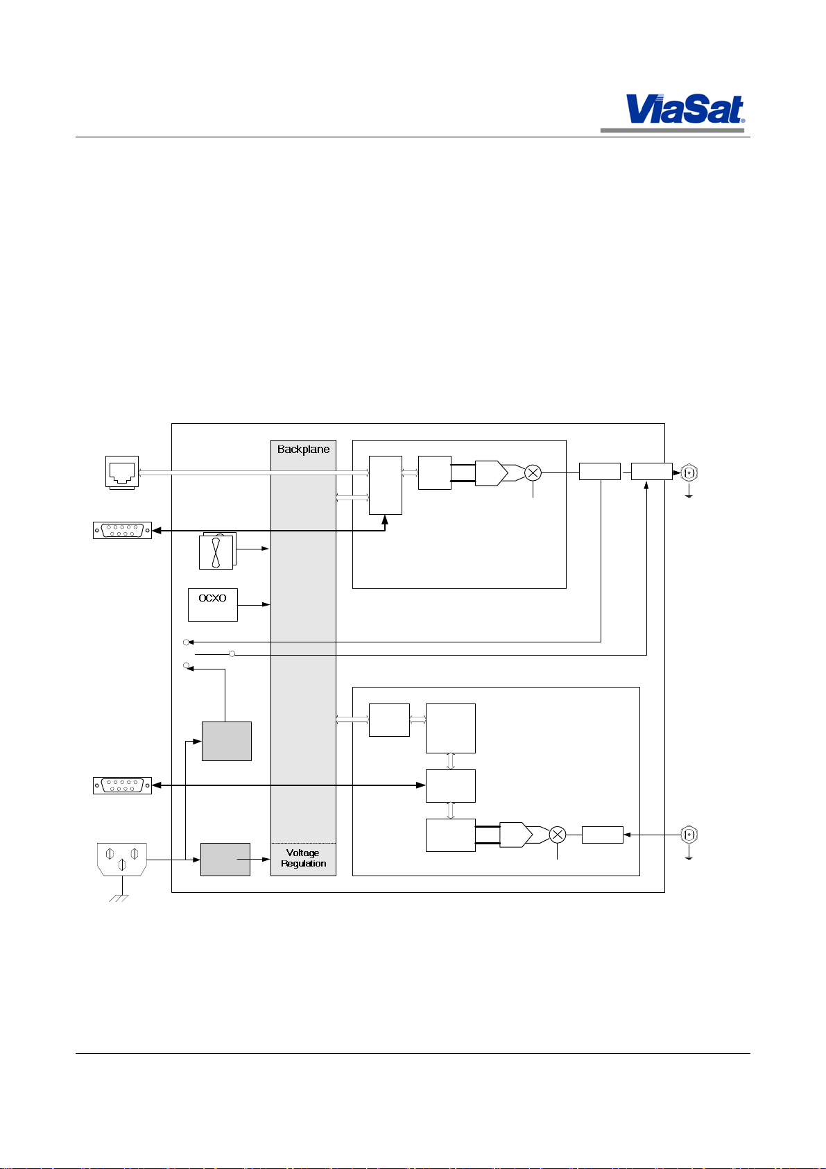
A block diagram of the VMBR-1520 is shown in Figure 1-3. The basic
components are described in the following paragraphs.
USER ENET (J8)
CPU
FPGA
CONSOLE (J5)
DAC
LO
Bias-T
Bias-T
Tx RF
(J2)
ACU (J4)
AC PWR (J1)
100 V to 240 V AC,
50 Hz to 6 Hz
Fans
80MHz
Power
Supply
Power
Supply
PCI
BUC
Bridge
DSP
Decoder
FPGA
Demod
FPGA
Figure 1-3. VMBR-1520 Functional Block Diagram
ADC
TXR
LFLR
Bias-T
LO
Rx RF
(J3)
1075152 Rev. 001
Page 25

VMBR-1520 Mobil e Broadband Router Installation, Operation, and Maintenance Guide
1-7
General Description
Power Distribution
The Power Supply accepts universal AC input - 100 VAC - 240 VAC,
50 Hz - 60 Hz, at a maximum current of 3 ampere. It is protected by a
250 V, 3 A, time-lag, circuit breaker which is part of the front panel AC
power switch. The AC switch controls the application of AC to the
Power Supplies. The Backplane uses Point-of-Load regulators to
convert the Power Supply output to the necessary DC voltages for
internal components.
Reference Signal
The VMBR-1520 contains a high-precision internal master reference for
all internal components. The reference is self contained and does not
require any configuration, calibration, or maintenance.
The VMBR-1520 provides a 10 MHz sine wave reference signal for the
BUC through the Tx RF port (J2), and for the LNB through the Rx RF
port (J3). The specifications for both reference signals can be found in
Table 1-2.
TXR
The TXR provides the transmit function for the Return Link, and also
serves as the command and control center of the modem. The
incoming user data enters the TXR through the User Ethernet port (J8).
User data comes in the form of TCP/IP packets. The TXR processes the
packets into a baseband data stream. The baseband data goes through
Forward Error Correction (FEC) encoding, filtering, symbol mapping,
and digital-to-analog (D/A) signal conversion. The D/A outputs, which
contains the in-phase (I) and quadrature (Q) analog waveforms, go
through a quadrature modulator to be upconverted to L-Band. The LBand Tx RF signal is then multiplexed with a 10 MHz reference and DC
power for the BUC before being applied to the Tx RF port (J2).
As the command and control center of the modem, the TXR configures
and controls the Forward and Return Link parameters, such as
frequency, data rate, etc. It also monitors the condition of the modem
and alerts the user in case of a fault condition.
Initial configuration and diagnostics of the modem is provided through
the console port (J5) on the TXR.
LFLR
The LFLR provides the receive function for the Forward Link. The
Forward Link is received from the antenna and passed to the modem as
an L-Band signal through the Rx RF port (J3). The Rx RF signal is
demodulated into baseband in-phase (I) and quadrature (Q) analog
waveforms. The I and Q signals go through analog-to-digital (A/D)
conversion, symbol mapping, filtering, FEC decoding, and reconstruction back into TCP/IP packets. The packets are transmitted to
the TXR where they will be sent to the user via the User Ethernet port
(J8). A 10 MHz reference and +18/12 V DC are provided to the antenna
LNB through the Rx RF port (J3).
Receive Signal Strength Indicator (RSSI) is provided by the LFLR to the
ACU through the ACU EIA-422 port (J4).
Rev. 001 1075152
Page 26

VMBR-1520 Mobile Broadband Router Installation, Operation, and Maintenance Guide
1-8
Item Function
Power
Preparation for Use and Installation
1.4.2 VMBR-1520 Front Panel Controls and Indicators
The VMBR-1520 front panel contains the controls and indicators shown
in Figure 1-4, and described in Table 1-3.
Figure 1-4. VMBR-1520 Front Panel
Table 1-3. VMBR-1520 Front Panel Controls and Indicators
AC Switch The main AC Power Switch for the modem. Flip the switch up to turn the
modem on, and down to turn the modem and off.
Status LEDs
PWR LED lights blue when power is applied.
BUC LED is off if BUC Switch (SW6) is set to 0 V.
LED lights green if BUC SEL Switch (SW6) is set to 18 V.
LED lights amber if BUC SEL Switch (SW6) is set to 24 V.
SAT LED blinks green when the modem has acquired the Satellite Forward Link.
LED lights green when the modem has logged into the ArcLight network.
LED blinks amber when the modem transmits on the Return Link.
LAN LED lights green when a link is established on the User Ethernet port (J8).
LED blinks amber when there is activity on the User Ethernet port (J8).
FAULT LED lights red when there is an internal failure of the modem or if there is
no forward link lock.
1075152 Rev. 001
Page 27

VMBR-1520 Mobil e Broadband Router Installation, Operation, and Maintenance Guide
2-9
Preparation for Use and Installation
2. Preparation for Use and Installation
2.1 Introduction
This section contains information for VMBR-1520 installation,
including recommended tools and test equipment, unpacking and
inspection, installation procedures, and connections. Items required for
setup, and operation are supplied by both the customer and ViaSat® as
listed in Table 1-1.
2.2 Tools and Test Equipment
Installation of the VMBR-1520 requires tools, test equipment, and
software as listed in Table 2-1. Items equivalent in function to those
listed may be substituted except for ViaSat® proprietary software.
Table 2-1. Recommended Installation Tools and Test Equipment
Part No Descript ion Manufacturer
Various Screwdriver, Phillips head, 6-in, nos. 1 and 2 Any
Various Screwdriver, flat-tip, 6-in, ¼ and ⅛-in blade Any
Various Personal computer with Ethernet and serial port Refer to Table 1-1.
Fluke 22 or equivalent Digital volt/ohm meter Fluke Corporation
HP8590 or 8560
series or equivalent
----- Various coaxial connectors as required Any
----- Crimp tools as required Any
Spectrum analyzer Hewlett Packard
Rev. 001 1075152
Page 28

VMBR-1520 Mobile Broadband Router Installation, Operation, and Maintenance Guide
2-10
Note
Initial installation and
Note
Installation
Preparation for Use and Installation
2.3 Hardware Installation
Installation of the VMBR-1520 hardware is described in the following
considerations including site
preparation, equipment
location, and cable lengths
should have been
previously determined by
the installer.
paragraphs.
Warning Risk of
electric shock. Always
ensure that the unit is
properly grounded to earth
ground. Primary safety
ground to the unit is
achieved through the 2 wire
plus ground IEC 320
appliance cord. Before
installing, verify earth
ground on the circuit
supplying power. If this
ground is missing or
unreliable then connect the
ground stud on the rear of
the unit to earth ground.
Grounding should be
verified by a professional
certified installer and
comply with any applicable
local codes.
2.3.1 Equipment Location
Installation and initial setup requires a customer-supplied PC with
terminal software that communicates over an EIA-232 serial interface.
configuration requires a
customer supplied PC.
The PC is used during the initial configuration process.
The VMBR-1520 and Antenna Subsystem are connected by coaxial
cables which are part of the Inter-Facility Link (IFL). Do NOT connect
the IFL cables until later in the procedures.
Figure 2-1. VMBR- 1520 Initial Basic Connections
Warning Do not drop
the equipment when lifting
or carrying. Personnel injury
or equipment damage may
occur.
1075152 Rev. 001
The VMBR-1520 is normally mounted in a standard 19-inch rack, but
may be placed on a tabletop, if desired.
1. If tape is provided, remove the protective tapes on the modem.
2. Mount the modem per one of the options as suggested in Paragraph
2.3.2.
3. √ After successfully completing the above steps, initial the table in
Appendix B.
Page 29

2-11
Caution The unit
draws its cooling air from
the left side panel air inlet.
The installer must verify that
the both side panels are not
obstructed, and that the
cooling air supplied to the
unit is maintained between
-5 °C and +55 ° C.
Caution The
maximum rated RMS
current of the unit is 3 A at
100 VAC - 240 VAC. The
power strips or outlet wiring
must be properly sized and
rated for the applicable
capacity. Primary safety
ground to the unit is
achieved through the 2-wire
plus ground IEC 320
appliance cord. If power
strips are used for power
distribution they must be
properly grounded to the
branch circuit and must
have approved outlets
incorporating safety ground.
VMBR-1520 Mobil e Broadband Router Installation, Operation, and Maintenance Guide
Preparation for Use and Installation
2.3.2 Mounting
Caution All mounting
screws are structurally
connected to the inside
frame of the chassis. Limit
screw penetration into
chassis a maximum of 0.25”
to avoid damaging internal
components.
The VMBR-1520 is designed to be rack mounted. The modem must be
mounted so that the side perforated areas are not obstructed. A
minimum clearance of 2 inches is required around the perforated areas
for adequate airflow. Viewed from the front, the air is pulled in at the
left side and exhausted out the right side.
Because installation requirements vary from site to site, ViaSat® does
not provide any mounting hardware, mounting feet or felt pads with the
modem. The installer is responsible for obtaining the necessary
brackets that best suit the need of each installation site.
All cable connections for the VMBR-1520 are made from the rear panel.
Allow adequate spacing between the modem’s rear panel to nearby
objects to accommodate the connection and routing of the cables.
1. Mount the VMBR-1520 as suggested above.
2. √ After successful completion of the above steps, initial the table in
Appendix B.
Rev. 001 1075152
Page 30

VMBR-1520 Mobile Broadband Router Installation, Operation, and Maintenance Guide
2-12
Preparation for Use and Installation
Front Panel
Rear Panel
Side Panel
Figure 2-2. VMBR-1520 Chassis Dimension and Mounting Features
1075152 Rev. 001
Page 31

VMBR-1520 Mobil e Broadband Router Installation, Operation, and Maintenance Guide
2-13
Ref
J2 Tx RF
N-
Type (F)
N-Type (M)
Return Link Transmitter Output
.
J3 Rx RF
TNC-Type (F)
TNC-Type (M)
Forward Link Receiver Input
.
J5 CONSOLE
DB-
9 (M) DB-
9 (F)
EIA-232 port for configuration and
SW6
SWS BUC SEL
--- --- Toggle
switch (BUC mode select).
J7 ACU ENET
RJ-
45 (F)
RJ-
45 (M)
Ethernet port for communication with
2.3.3 VMBR-1520 Connections and Descriptions
All VMBR-1520 connections are on the rear panel as shown in Figure
2-3. Refer to Table 2-2, and the following paragraphs for details.
Figure 2-3. VMBR-1520 Rear Panel
Table 2-2. Rear Panel Connections and Components
Preparation for Use and Installation
Desig
J1 AC PWR IEC 320-C14 IEC 320-C13 AC input power.
J4 ACU DB-9 (F) DB-9 (M) EIA-422 port for communication with
J8 USER ENET RJ-45 (F) RJ-45 (M) Ethernet port for communication with
--
Label Type Mating Connector Description/Function
See Table 1-2 for specifications.
50 Ω
50 Ω
--- --- Earth ground, 8-32 UNC thread.
50 Ω
50 Ω
See Table 1-2 for specifications.
See Table 1-2 for specifications.
the ACU to relay RSSI information.
See
Table 2-3
diagnostic with a support PC/laptop.
See
Table 2-4
See
Table 1-3
indications.
the ACU network (for future use).
See Table 2-5 for pin description.
the end user network.
See Table 2-5 for pin description.
for pin description.
for pin description.
for settings and
Rev. 001 1075152
Page 32

VMBR-1520 Mobile Broadband Router Installation, Operation, and Maintenance Guide
2-14
Pin Signal
Desc
ription
Preparation for Use and Installation
2.3.3.1 Coaxial Connections
DC power to the BUC and LNB are provided by the VMBR-1520
Warning Do not
disconnect the IFL cables to
the antenna when the unit is
powered on. A DC voltage is
present on the IFL cables.
The unit could suffer damage
if the IFL cable is
through the Tx and Rx IFL coaxial cables. These cables need to be
properly sized for the current capacity and to minimize voltage drop
across the cables.
Both Tx RF (J2) and Rx RF (J3) ports have a characteristic impedance
of 50 Ω. The IFL cables should have a characteristic impedance of 50 Ω
to minimize reflection on the cables and ensure maximum power
transfer from the modem to the antenna.
accidentally dropped onto a
metal object.
2.3.3.2 ACU Connections
Communication between the VMBR-1520 and the ACU can be made via
the serial EIA-422 interface.
To use the serial EIA-422 interface, connect a 9-pin serial cable
between the ACU’s EIA-422 port and the modem’s ACU port (J4). Refer
to Table 2-3 for pin descriptions. All signal names are relative to the
modem.
Table 2-3. ACU Port (J4) Pin Descriptions
1 SHLD+ Cable Shield
2 TXD+ Transmit Data +
3 RXD+ Receive Data +
4 GND Ground
5 GND Ground
6 N/C -7 TXD- Transmit Data 8 RXD- Receive Data 9 N/C --
1075152 Rev. 001
Page 33

2-15
2.3.3.3 Console Connections
Pin Signal
Description
Pin Signal
Description
Note
The end user is
VMBR-1520 Mobil e Broadband Router Installation, Operation, and Maintenance Guide
Preparation for Use and Installation
For initial setup and configuration, connect a 9-pin null-modem serial
cable between the support PC’s D-connector (COM port) and the
modem’s CONSOLE port (J5). This connector is not normally used
during normal operation and should be covered by the supplied dust
cap. Refer to Table 2-4 for pin descriptions. All signal names are
relative to the modem.
Table 2-4. Console Port (J5) Pin Descriptions
1 N/C -2 RXD Receive Data
3 TXD Transmit Data
4 N/C -5 GND Ground
6 N/C -7 N/C -8 N/C -9 N/C --
2.3.3.4 User Data Connections
responsible for interfacing
their Ethernet network to the
unit.
The VMBR-1520 interfaces with the end user Ethernet network via the
USER ENET port (J8).
Connect a CAT5 Ethernet cable between the end user Ethernet network
Router and the modem’s USER ENET port (J8). Refer to Table 2-5 for
pin descriptions.
Table 2-5. USER ENET Port (J8) Pin Descri ptions
1 TX+ Transmit Data +
2 TX- Transmit Data 3 RX+ Receive Data +
4 N/C -5 N/C -6 RX- Receive Data 7 N/C -8 N/C --
Rev. 001 1075152
Page 34

VMBR-1520 Mobile Broadband Router Installation, Operation, and Maintenance Guide
2-16
Pin Signal
Descripti
on
Note
Continue with Section
Note
The end user is
Preparation for Use and Installation
2.3.3.5 ACU Data Connections
The VMBR-1520 interfaces with the ACU Ethernet network via the ACU
ENET port (J7).
responsible for interfacing
the ACU Ethernet network
to the unit.
Connect a CAT5 Ethernet cable between the end user Ethernet network
Router and the modem’s USER ENET port (J8). Refer to Table 2-6 for
pin descriptions.
Table 2-6. ACU ENET Port (J7) Pin Descriptions
1 TX+ Transmit Data +
2 TX- Transmit Data 3 RX+ Receive Data +
4 N/C -5 N/C -6 RX- Receive Data 7 N/C -8 N/C --
2.3.3.6 BUC Power Connections
The VMBR-1520 provides a switch on the rear panel allowing the user
to select the proper BUC power to the BUC. User can select (1) No BUC
power (0 VDC), (2) 18 VDC at 1 A, or (3) 24 VDC at 4 A.
2.3.3.7 Input Power
The VMBR-1520 accepts universal AC input through the AC PWR port
(J1). Each modem is shipped with an AC power cord for use in North
America.
1. Make sure all wire and cable connections are correct and securely
2. Connect the power cord to the IEC 320 receptacle (J1) on the rear of
3. √ After the above steps are successfully completed, initial the table
2.3.4 Additional Equipment
Refer to Vendor documentation for installation procedures of any
3 for initial setup and
configuration.
additional equipment that is not provided by ViaSat® but is still
required for proper operation of the system. This includes antenna
configuration and alignment to the vehicle.
attached.
the modem and plug the other end into the power source. Do NOT
turn on power to the modem until told to do so.
in Appendix B.
1075152 Rev. 001
Page 35

VMBR-1520 Mobil e Broadband Router Installation, Operation, and Maintenance Guide
3-1
Note
Ensure all procedures
Initial Set Up and Configuration
3. Initial Set Up and Configuration
3.1 Introduction
This section contains information required to configure the VMBR-1520
in section 2 have been
completed before
attempting to operate the
equipment.
3.1.1 Quick Guide and Summary
Table 3-1. VMBR-1520 Set Up Quick Guide and Summary
Para. Action Summary
3.2.1 Parameters Required Before Configuring
the VMBR-1520
3.2.2 Other Requirements Before Configuring
the VMBR-1520
3.2 Initial Setup and Checkout Steps to set up the modem and verify overall system
3.3.1 Power On
3.3.2 Verify Operational Status Verify modem operation, satellite acquisition, link status,
3.3.2.1 Ping the Ping the modem from the PC.
3.3.2.2 Verify Satellite Acquisition Status Check modem and satellite acquisition status, signal
3.3.2.3 Ping the Hub Test Server Ping the hub test server from the modem.
3.3.2.4 Connect to the Hub Test Web Page Connect to the hub’s test web server.
3.3.3 Normal Operation
3.3.3.1 Verify Subscription Status
3.3.3.2
Verify Connection to the
to acquire a satellite network, verify the connection, and begin normal
operation. Once configured, the modem is remotely controlled by the
network.
Corrective action is included in the event that the modem is unable to
acquire a satellite network, or if power levels are not correct.
Each VMBR-1520 has been pre-configured at the factory to operate on
the target satellite network. Minimal configuration is required at the
target site. A summary of actions necessary to set up the VMBR-1520
is listed in Table 3-1. During set up, refer to subsequent paragraphs
for details.
Determine target site installation parameters before
initial configuration of the modem.
Verify installation is complete and modem is ready for
initial configuration.
operation and connectivity over the air.
Turn on the modem for the first time after installation.
and connection to the hub and the Internet.
lock, login and registration with hub.
Internet
Attempt connection to the Internet.
Check modem subscription status with satellite operator.
Connect to the Internet and WWW.
Rev. 001 1075152
Page 36

VMBR-1520 Mobile Broadband Router Installation, Operation, and Maintenance Guide
3-2
Note
The terminal must be
Note
The unit has been
Initial Set Up and Configuration
3.2 Preparation for Initial Setup
Satellite testing cannot be performed unless the hub is operational and
the modem information has been entered into the hub database.
configured for the satellite
and earth station
parameters at each
location.
The antenna should have a clear, unobstructed view to the sky. No
physical obstruction shall be placed directly between the antenna and
the sky. Please note heavy rain and/or cloud cover can reduce satellite
signal levels enough to make the modem inoperable.
3.2.1 Parameters Required Before Configuring the VMBR-1520
Before beginning the configuration process, the installer must know the
parameter values for the target site. A list of required parameters is
pre-configured at the factory
to operate on the target
satellite network. Refer to
Paragraph 3.4 in the
unlikely situation where the
unit has to be re-configured.
shown in Appendix A. Contact the satellite operator to obtain the
necessary parameters, and fill in the values in the table in Appendix A.
When all values are determined, return here and continue with the next
step.
√ After successfully filling in the values in Appendix A, initial the table
in Appendix B.
3.2.2 Other Requirements Before Configuring the VMBR-1520
Before configuring the modem, ensure the following items are
completed:
Warning Power to all
devices must be turned off
during installation to avoid
injury and/or damage to
equipment.
1. All units are powered off.
2. The antenna, ACU, and IFL cables are properly installed and
verified according to the manufacturers’ procedures.
3. The modem is properly mounted and connected to the ACU and
antenna.
4. The modem is properly connected to an AC source per Paragraph
2.3.3.7.
5. A PC is connected to the same LAN as the modem, and the PC’s IP
address is configured on the same LAN as the modem.
6. All items in Appendix A are complete.
7. √ After successfully completing the above steps, initial the table in
Appendix B.
1075152 Rev. 001
Page 37

VMBR-1520 Mobil e Broadband Router Installation, Operation, and Maintenance Guide
3-3
N
ote In an emergency
Note
The lack of a forward
3.3 Initial Setup and Checkout
3.3.1 Power On
To power on the modem, perform the following procedures:
condition, such as fire or
smoke conditions, turn the
equipment off using the
power switch on the
equipment. If the
emergency condition cannot
be resolved, remove power
at the main circuit breakers
in the facility.
1. Verify that items in Paragraphs 3.2.1 and 3.2.2 are completed.
2. Turn on the ACU and antenna as suggested by the manufacturers.
3. Toggle the power switch at the front of the modem. Observe the
power indicator on the modem front panel lights. Wait
approximately two minutes for the modem to power up fully.
4. If the modem powers up, proceed to the next section.
5. √ After successfully completing the above steps, initial the table in
Appendix B, and proceed to the next section.
Initial Set Up and Configuration
link signal will result in a
fault indication
Caution If the unit has
been exposed to extremely
hot or cold environments, let
the internal temperature
stabilize before turning it on.
Refer to Paragraph 6.6 for troubleshooting procedures if the modem
cannot be powered on.
3.3.2 Verify Operational Status
The modem’s operational status is verified through the following steps:
1. Ping the modem through the User Ethernet port (Paragraph
3.3.2.1).
2. Query Satellite Acquisition status (Paragraph 3.3.2.2).
3. Ping the hub test server (Paragraph 3.3.2.3).
4. Load hub test web page (Paragraph 3.3.2.4).
5. Verify user subscription (Paragraph 3.3.3.1).
6. Access the Internet (Paragraph 3.3.3.2).
Rev. 001 1075152
Page 38

VMBR-1520 Mobile Broadband Router Installation, Operation, and Maintenance Guide
3-4
Note
Make sure that
the
Initial Set Up and Configuration
3.3.2.1 Ping the Modem
On the PC, open a command prompt, and enter ping a.b.c.d –t where
support PC’s IP address is
configured to operate on the
same network and subnet
as the VMBR-1520.
a.b.c.d is the IP address of the modem, i.e. ping 192.168.0.1 –t. The
command prompt window should display echo replies as shown in
Figure 3-1. Press CTRL-C to cancel the ping command. The ping echo
verifies the modem’s connectivity.
Figure 3-1. Ping the VMBR-1520
√ After successfully completing the above steps, initial the table in
Appendix B, and proceed to the next section.
Refer to Paragraph 6.6.2 for troubleshooting procedures if the modem
does not respond to the ping command.
1075152 Rev. 001
Page 39

VMBR-1520 Mobil e Broadband Router Installation, Operation, and Maintenance Guide
3-5
3.3.2.2 Verify Satellite Acquisition Status
On the PC, open a web browser. At the browser’s address bar, enter
the Uniform Resource Locator (URL), or web address, of the modem, i.e.
http://192.168.0.1. When a pop-up window appears, enter ADMIN
(capital case) as username, and arclightas the password then press
Enter. The web browser should display the modem’s System Status
web page as shown in Figure 3-2.
Initial Set Up and Configuration
Figure 3-2. VMBR- 1520 System Status Web Page
In the System Status web page, verify the following:
1. MBS System Status should be Online.
2. Modem Status → Modem State should be Logged In.
3. Modem Status → Signal Quality should be more than 2.0 dB Eb/No.
√ After successfully completing the above steps, initial the table in
Appendix B, and proceed to the next section.
Refer to Paragraph 6.6.3 for troubleshooting procedures if the modem
does not provide any of the above status.
Refer to Paragraph 5.2.2 for a description of the parameters and their
allowable states.
Rev. 001 1075152
Page 40

VMBR-1520 Mobile Broadband Router Installation, Operation, and Maintenance Guide
3-6
Note
Contact the satellite
Initial Set Up and Configuration
3.3.2.3 Ping the Hub T est Server
On the PC or laptop, open a command prompt, and enter
ping a.b.c.d –t where a.b.c.d is the IP address of the hub test server,
operator or service provider
for the hub test server’s IP
address.
i.e. ping 204.14.40.60 –t. The command prompt window should
display echo replies as shown in Figure 3-3. Press CTRL-C to cancel the
ping command. The ping echo verifies the modem connectivity.
Figure 3-3. Ping the Hub Test Server
√ After successfully completing the above steps, initial the table in
Appendix B, and proceed to the next section.
Refer to Paragraph 6.6.4 for troubleshooting procedures if the modem
could not receive any ping response from the hub test server.
1075152 Rev. 001
Page 41

VMBR-1520 Mobil e Broadband Router Installation, Operation, and Maintenance Guide
3-7
Note
Contact the satellite
3.3.2.4 Connect to the Hub Test Web Page
On the support PC, open a web browser. At the browser’s address bar,
enter the Uniform Resource Locator (URL), or web address, of the hub’s
operator or service provider
for the hub test web server’s
URL or web address.
test web server, i.e. http://204.14.40.60. Check to see what the actual
IP address is. The web browser should display a test web page similar
to the one shown in Figure 3-4.
Initial Set Up and Configuration
Figure 3-4. Sample Hub Test Web Page
Click the Click to start MySpeed button to begin a speed test. The
Forward and Return Link throughput will be displayed at the end of the
speed test. If necessary, verify that the throughput is consistent with
the end user’s subscription plan.
√ After successfully completing the above steps, initial the table in
Appendix B, and proceed to the next section.
Refer to Paragraph 6.6.5 for troubleshooting procedures if the modem
could not display the hub test web page from the hub test web server.
Rev. 001 1075152
Page 42

VMBR-1520 Mobile Broadband Router Installation, Operation, and Maintenance Guide
3-8
Initial Set Up and Configuration
3.3.3 Normal Operation
3.3.3.1 Verify Subscription Status
The installer should verify with the service provider that the modem has
been commissioned in the hub, and that a subscription is active for the
modem.
Refer to the procedure supplied by the service provider to verify user
subscription status.
√ After successfully confirming active subscription status, initial the
table in Appendix B, and proceed to the next section.
3.3.3.2 Verify Connection to the Internet
On the support PC, open a web browser. At the browser’s address bar,
enter an Internet web page address, i.e. http://www.viasat.com. The
web browser should display ViaSat’s company web page, and the
modem is verified and ready for operation.
√ After successfully completing the above steps, initial the table in
Appendix B.
Refer to Paragraph 6.6.6 for troubleshooting procedures if the modem
could not display the web page.
1075152 Rev. 001
Page 43

VMBR-1520 Mobil e Broadband Router Installation, Operation, and Maintenance Guide
3-9
Note
Contact the satellite
3.4 Modem Reconfiguration
Each VMBR-1520 has been pre-configured at the factory to operate on
the target satellite network, and requires minimal configuration per
Paragraph 3.3 at the target installation site. This section is only
required if the modem, in the unlikely event, requires a complete reconfiguration.
3.4.1 Preparation
To prepare the modem for reconfiguration, perform the following steps:
1. Connect the modem per Paragraph 3.2.2.
2. In addition to Step (1), connect a null-modem cable (Table 1-1 and
Paragraph 2.3.3.3) from the support PC’s serial port to J5 on the
modem.
3. Turn the modem on, and let it run for about two minutes.
4. On the support PC, open a terminal communication program, i.e.
HyperTerminal. Set up the program with the correct serial port, i.e.
COM1. Configure the serial port to 19200 bit/s, eight (8) data bits,
no parity bit, and one (1) stop bit.
5. Once the terminal communication program has been properly
configured, press <Enter> and the command prompt # will appear.
Initial Set Up and Configuration
3.4.2 Reconfiguration Details
At the # prompt, type termcfg and press <Enter>. At the Main Menu
(Paragraph 5.2.1), select the proper menu in the following paragraphs,
and configure the highlighted items as shown. The following screens
are just an example. The correct parameters should be provided to you
by the network operator. When finished, type x to exit back to the Main
Menu.
3.4.2.1 General Parameters Menu
Please enter menu item: 0000
General Parameters
A - Ini Boot Flag(Read-only) 0
B - Terminal IP Address 192.168.0.1
C - Terminal IP Mask 255.255.255.0
D - Network ID
E - MAC Address(Read-only) 00:A0:BC:02:CA:AF
operator or service provider
for the unit’s Network ID
(Parameter D).
F - Hardware Revision(Read-only) 16
G - Board Startup Date(Read-only) 04/15/07
I - Antenna Type 11
J - Terminal Type 25
K - Terminal Platform Type 150
Z - Help Menu
X - Exit Menu
Please enter menu item: xxxx
192.168.0.1
192.168.0.1192.168.0.1
255.255.255.0
255.255.255.0255.255.255.0
1033 (4.9)
1033 (4.9)
1033 (4.9)1033 (4.9)
11
1111
25
2525
150
150150
Rev. 001 1075152
Page 44

VMBR-1520 Mobile Broadband Router Installation, Operation, and Maintenance Guide
3-10
Initial Set Up and Configuration
3.4.2.2 Satellite Parameters Menu
Please enter menu item: 1111
Satellite Parameters
A - Network Address 10.61.0.0
B - Network Mask 255.255.0.0
C - Gateway Address 10.61.255.254
D - Satellite ID 2
E - Transponder Number 12
F - Longitude -22.00 deg
G - Polarization Cant Angle +0.00 deg
H - Polarization Type Vertical Linear
I - Satellite Search on
Z - Help Menu
X - Exit Menu
Please enter menu item: xxxx
3.4.2.3 ACU Parameters Menu
Please enter menu item: 2222
ACU Parameters
A - Antenna Position Toward Aircraft Nose
B - Roll Offset +0.00 deg
C - Pitch Offset +0.00 deg
D - Yaw Offset +0.00 deg
E - Azimuth Error Limit +5.00 deg
F - Elevation Error Limit +5.00 deg
G - Polarization Error Limit +5.00 deg
H - LNB Source 11.70-12.25 GHz
I - Aircraft Major GulfStream
J - Aircraft Minor G550
K - GIV Flap 0
L - Flap Offset 1 +0.00 deg
M - Flap Offset 2 +0.00 deg
N - Flap Offset 3 +0.00 deg
O - Flap Offset 4 +0.00 deg
P - IP Address 192.168.0.2
Q - IP Mask 255.255.255.0
R - Gateway IP Address 127.0.0.1
S - Port Number 7915
T - Fixed Latitude +33.07 deg
U - Fixed Longitude -117.16 deg
V - ACU Type Serial 0
W - ACU Status Msg Rate 1111 (times/sec)
Y - ACU RSSI Msg Rate 60
Z - Help Menu
X - Exit Menu
Please enter menu item: xxxx)
10.61.0.0
10.61.0.010.61.0.0
255.255.0.0
255.255.0.0255.255.0.0
10.61.255.254
10.61.255.25410.61.255.254
on
onon
Serial 0
Serial 0Serial 0
60 (times/sec
6060
1075152 Rev. 001
Page 45

VMBR-1520 Mobil e Broadband Router Installation, Operation, and Maintenance Guide
3-11
3.4.2.4 Forward Link Parameters Menu
Please enter menu item: 3333
Forward Link Parameters
A - Frequency 70000000 Hz
B - Data Rate 7000000 bps
C - Modulation Type QPSK
D - Spread Factor 1
E - PN Tap 0x0001
F - PN Seed 0x8787
G - Preamble 0xDA46A8C0
H - Truncation Count 8
I - Iteration Number 8
J - Scramble on
K - OTA/IF OTA
L - Attenuator 100 dB
M - L-band Frequency 1351000000 Hz
N - IP Address 10.254.0.1
O - IP Mask 255.255.0.0
P - IP Flags 0x0F
Q - Filter IP Address 0.0.0.0
R - Filter IP Mask 0.0.0.0
S - Link Blockage Time 11 secs
U - LNB State 1
V - Duplicate Mode 0
W - LNB Voltage 1111 (18V)
Z - Help Menu
X - Exit Menu
Please enter menu item: xxxx
Initial Set Up and Configuration
3.4.2.5 Return Link Parameters Menu
Please enter menu item: 4444
Return Link Parameters
(Only Initial Startup parameters.
NMS will adjust accordingly when the terminal logs in)
A - Frequency KuBand: 14401000000 Hz
L-Band: 1351000000 Hz
B - Data Rate 512000 bps
C - Chip Ratio 24
D - Packet Size 1
E - Long PN Seed 0x000001
F - Long PN Tap 0xC20001
G - Short PN Seed 0x0009
H - Short PN Tap 0x0342
I - Power 16.0
J - Preamble 0xC6DFA688
K - Power Limit 5555.0
L - TXB State 1
16.0 dB
16.016.0
.0 dB
.0.0
Rev. 001 1075152
Page 46

VMBR-1520 Mobile Broadband Router Installation, Operation, and Maintenance Guide
3-12
Initial Set Up and Configuration
3.4.2.6 Network Link Parameters Menu
Please enter menu item: 5555
Network Link Parameters
A - DHCP Server on
B - NAT on
C - DNS Cache oooonnnn
D - Multicast Server off
E - SCPS off
F - DHCP IP Pool Start 192.168.0.11
G - DHCP IP Pool End 192.168.0.254
H - DHCP Domain Name viasat.com
I - NAT Type dynamic
J - NAT Server Address 192.168.0.3
K - DNS Primary Address
L - DNS Secondary Address
M - DNS Purge Time 1800
N - Multicast Address 224.0.0.0
O - Multicast Mask 224.0.0.0
P - MAR Router off
Q - MAR VLAN Address 1 0.0.0.0
R - MAR VLAN Mask 1 255.255.255.0
S - MAR VLAN Address 2 0.0.0.0
T - MAR VLAN Mask 2 255.255.255.0
U - MAR VLAN Address 3 0.0.0.0
V - MAR VLAN Mask 3 255.255.255.0
W - Multicast Origin Address 0.0.0.0
Y - Web Server on
204.14.40.44
204.14.40.22
on
onon
on
onon
off
offoff
off
offoff
204.14.40.44
204.14.40.44204.14.40.44
204.14.40.22
204.14.40.22204.14.40.22
on
onon
3.4.2.7 SCPS Parameters Menu
Please enter menu item: 6666
SCPS Parameters
A - SCPS Hub IP Address 10.2.1.30
B - Local Port 7168
C - Remote Port 7168
D - Compression off
E - NAT off
F - Mangle on
G - Hard Routes on
I - P2P Address 10.99.99.99
J - Satellite TX Buffer Size 20000
K - Satellite RX Buffer Size 525000
L - Satellite CC Value 0
M - Satellite Timeout Value 800000
N - Satellite MTU Value 1500
O - LAN CC Value 1
P - LAN TCP Only Value 1
Q - LAN MTU Value 1472
R - Port 1 Hole 0
S - Port 2 Hole 0
T - Port 3 Hole 0
off
offoff
3.4.2.8 Miscellaneous Parameters Menu
Please enter menu item: 7777
Miscellaneous Parameters
A - SNMP Trap Name skylinkAITR
B - SNMP IP Address 1 10.1.1.10
C - SNMP IP Address 2 10.1.1.11
D - SNMP IP Address 3 0.0.0.0
E - Scan Period 2000
1075152 Rev. 001
F - Scan Reads 1
G - Scan Spacing 1
Page 47

VMBR-1520 Mobil e Broadband Router Installation, Operation, and Maintenance Guide
3-13
3.4.2.9 Calibration Paremeters
Please enter menu item: 8888
Calibration Parameters
A - DAC0 (Fine Attn) 0
B - DAC1 (I Gain) 66
C - DAC2 (I DC offset) 112
D - DAC3 (Q DC offset) 112
E - Step Attenuator 0x0002
F - Baseband AGC Gain 0x0167
3.4.3 Post Reconfiguration Reboot
When the reconfiguration outlined in Paragraph 3.4.2 is completed,
save the settings and reboot the modem per Paragraph 4.2.
0x0002
0x00020x0002
0x0167
0x01670x0167
Operating Procedures
Rev. 001 1075152
Page 48

VMBR-1520 Mobile Broadband Router Installation, Operation, and Maintenance Guide
4-14
Operat ing Procedures
4. Operating Procedures
4.1 Introduction
This section contains additional information for operating the VMBR1520 through the serial console port, including rebooting the modem,
checking and adjusting Forward Link and Return Link parameters, and
verifying ACU and Network Management System (NMS) status.
4.2 Rebooting the Modem
The general menu is shown below. Enter r and then enter y and y
again to confirm the reboot. The Telnet session will be terminated, and
the modem will perform a software reboot.
Main Menu
0 - General Parameters
1 - Satellite Parameters
2 - ACU Parameters
3 - Forward Link Parameters
4 - Return Link Parameters
5 - Network Parameters
6 - SCPS Parameters
7 – Miscellaneous Parameters
8 – Calibration Parameters
9 – Overhead Parameters
A - ACU Installation Setting
R – Reboot
S – System Status
U – Upgrade Terminal Software
V – Version Information
X - Exit Program
Please enter menu item: rrrr
Do you want to reboot the terminal (y/n)? yyyy
Are you SURE you want to reboot the terminal (y/n)? yyyy
1075152 Rev. 001
Page 49

VMBR-1520 Mobil e Broadband Router Installation, Operation, and Maintenance Guide
4-15
4.3 Adjusting Return Link Power
During normal operation, once the VMBR-1520 is logged into the
network, the Return Link transmit power is dynamically adjusted by
the ArcLight Network Control for optimal performance. No user
intervention is required.
The following example demonstrates setting the Return Link transmit
power during initial startup. The highlighted parameters are used to
set the proper initial transmit power when the modem is attempting to
log into the network. The parameter Power (Item I) sets the initial
transmit power to be x dB below the maximum transmit power. The
parameter Power Limit (Item K) sets the maximum allowable transmit
power to avoid saturating the BUC and the Power Amplifier.
In the Main Menu, select item 4 – Return Li nk Parameters.
Return Link Parameters
(Only Initial Startup parameters.
NMS will adjust accordingly when the terminal logs in)
A - Frequency KuBand: 14401000000 Hz
L-Band: 1351000000 Hz
B - Data Rate 256000 bps
C - Chip Ratio 24
D - Packet Size 1
E - Long PN Seed 0x000001
F - Long PN Tap 0xC20001
G - Short PN Seed 0x0009
H - Short PN Tap 0x0342
I - Power 24
J - Preamble 0xC6DFA688
K - Power Limit 5555.0 dB
L - TXB State 1
Z - Help Menu
X - Exit Menu
Please enter menu item: xxxx
24.0 dB
.0 dB
2424
.0 dB.0 dB
.0 dB
.0 dB.0 dB
Operating Procedures
Enter in the desired attenuator value setting (higher value means lower
transmitter output power and lower value means higher transmitter
output power).
Enter Return Link Power (x.x dB): 20
Return Link Parameters
(Only Initial Startup parameters.
NMS will adjust accordingly when the terminal logs in)
A - Frequency KuBand: 14401000000 Hz
L-Band: 1351000000 Hz
B - Data Rate 256000 bps
C - Chip Ratio 24
D - Packet Size 1
E - Long PN Seed 0x000001
F - Long PN Tap 0xC20001
G - Short PN Seed 0x0009
H - Short PN Tap 0x0342
I - Power 20
J - Preamble 0xC6DFA688
K - Power Limit 5555.0 dB
L - TXB State 1
Z - Help Menu
X - Exit Menu
Please enter menu item: xxxx
Rev. 001 1075152
20.0
.0
2020
.0.0
20.0
.0 dB
dB
2020
.0 .0
dBdB
.0 dB
.0 dB.0 dB
Page 50

VMBR-1520 Mobile Broadband Router Installation, Operation, and Maintenance Guide
4-16
Operat ing Procedures
4.4 Checking Forward Link State and Activity
In the Main Menu, select item S – System Status.
The Forward Link State is shown in the Link State variable and should
show Locked. The IP Packets RX and the FLR Packets RX values
should be incrementing when the modem is receiving data. The FLR
Drop Filt value should be incrementing to indicate data is flowing to
other modems in the network. Press <Enter> to refresh the data.
When finished viewing the data, use x to exit.
System Status
NMS/ACU Status
NMS Login State: Terminal Logged In
Terminal State: Transmit Enabled
ACU State: On-Line Tx Inhibit: Off
ACU Temp +000 C Aircraft Type: Gulfstream G500
Ret Data Rate 256000 bps Ret Chan Freq: 1351000000 Hz
Doppler Freq +0 Hz DOS Velocity: +0 knots
Attenuator 24.5 dB EIRP: +0.00 dBm
Forward Link Status
Link State: Locked
FLR Frequency: 383 Hz FLR Chip Rate: 20999976 cps
EbNo: 12.19 dB State: New
Amplitude: 23.13 dB State: New
IP Packets RX: 0x000001D0
FLR Packets RX: 0x00000DA7 Drop Full: 0x00000000
FLR Drop Filt: 0x00000BD7
FLR Drop Length: 0x00000000 FLR AGC: 0x018B4DE1
L70 LO2 Lock: Locked Syn Lock: Locked
L70 93 MHz Lock: Locked RX18V Alarm: Okay
Return Link Status
300 Lock: Locked LO Lock: Locked
RX18V Alarm: Okay TX18V Alarm: Okay
Power Over Temp: Okay Power Fail: Okay
Tx Inhibit: Inactive Fan Tach: 77
IP Packets TX: 0x00000735 Errors: 0x00000000
TXR Temp: +28 C Chassis Temp: +28 C
FAN: 2280 RPM
A - Display ACU Status Menu
X - Exit Menu
Please enter menu item: xxxx
Locked Power State: Okay
LockedLocked
0x000001D0 Errors: 0x00000000
0x000001D00x000001D0
0x00000BD7 Drop CRC: 0x0000012A
0x00000BD70x00000BD7
1075152 Rev. 001
Page 51

4-17
4.5 Checking ACU State
In the Main Menu, select item S – System Status. Then, in the System
Status menu, select item A - Display ACU Status menu.
The ACU State is shown in the ACU State variable and should be OnLine. If it shows OFF-LINE, there is a problem with the ACU or the
connection to the ACU. The Tx Inhibit value should be Off to enable
Return Link transmission. Press <Enter> to refresh the data. When
finished viewing the data, use x to exit.
ACU Status
ACU State: On
ACU Temp +044 C Aircraft Type: Gulfstream G450/G500
ACU Faults
ACU Fault: None IRU Fault: None
PA Temp: None TX Lockout: Inactive
Mech Stop: None Pol Motor: None
Elev Motor: None Azi Motor: None
429 Chan 1: None 429 Chan 2: None
POST 429 Cntrlr: None POST Ant Cal: None
Ant Calibrate: Cal Off ACU Inhibit: None
ACU Stats
Update Time: 10881977
429 Chan 1 Good: 00000000 429 Chan1 Bad: 00000000
429 Chan 2 Good: 00000000 429 Chan2 Bad: 00000000
Ethernet Good: 00000000 Ethernet Bad: 00000000
Flap 0: Inactive Flap 1: Inactive
Flap 2: Inactive Flap 3: Inactive
Azimuth: 0.00 Elevation: +0.00
Polarization: +0.00
B - Display General Status Menu
X - Exit Menu
Please enter menu item: xxxx
VMBR-1520 Mobil e Broadband Router Installation, Operation, and Maintenance Guide
Operating Procedures
On----Line
Line Tx Inhibit: Off
OnOn
LineLine
Off
OffOff
Rev. 001 1075152
Page 52

VMBR-1520 Mobile Broadband Router Installation, Operation, and Maintenance Guide
4-18
Operat ing Procedures
4.6 Checking NMS State
In the Main Menu, select item S – System Status.
The NMS state is shown in the NMS Login State variable. If the modem
has completed the NMS login procedure, the variable should show
Terminal Logged In. If it does not indicate this, there is either a fault
in the system or the modem has not waited long enough to complete
the login process. The Terminal State should show that the modem is
in the Transmit Enabled state. Any other state indicates a problem in
the system. Press <Enter> to refresh the data. When finished viewing
the data, use x to exit.
System Status
NMS/ACU Status
NMS Login State: Terminal Logged In
Terminal State: Transmit Enabled
ACU State: On-Line Tx Inhibit: Off
ACU Temp +000 C Aircraft Type: Gulfstream G500
Ret Data Rate 256000 bps Ret Chan Freq: 1351000000 Hz
Doppler Freq +0 Hz DOS Velocity: +0 knots
Attenuator 24.5 dB EIRP: +0.00 dBm
Forward Link Status
Link State: Locked Power State: Okay
FLR Frequency: 383 Hz FLR Chip Rate: 20999976 cps
EbNo: 12.19 dB State: New
Amplitude: 23.13 dB State: New
IP Packets RX: 0x000001D0 Errors: 0x00000000
FLR Packets RX: 0x00000DA7 Drop Full: 0x00000000
FLR Drop Filt: 0x00000BD7 Drop CRC: 0x0000012A
FLR Drop Length: 0x00000000 FLR AGC: 0x018B4DE1
L70 LO2 Lock: Locked Syn Lock: Locked
L70 93 MHz Lock: Locked RX18V Alarm: Okay
Return Link Status
300 Lock: Locked LO Lock: Locked
RX18V Alarm: Okay TX18V Alarm: Okay
Power Over Temp: Okay Power Fail: Okay
Tx Inhibit: Inactive Fan Tach: 77
IP Packets TX: 0x00000735 Errors: 0x00000000
TXR Temp: +28 C Chassis Temp: +28 C
FAN: 2280 RPM
A - Display ACU Status Menu
X - Exit Menu
Please enter menu item: x
Terminal Logged In
Terminal Logged InTerminal Logged In
Transmit Enabled
Transmit EnabledTransmit Enabled
1075152 Rev. 001
Page 53

VMBR-1520 Mobil e Broadband Router Installation, Operation, and Maintenance Guide
5-1
Menu
Purpose
Para
graph
VMBR-1520 Configuration Menu Reference
5. VMBR-1520 Configuration Menu Reference
5.1 Introduction
This section contains the VMBR-1520 Configuration Menus available
for the user through the serial console port. The commands are used to:
1. Configure the modem for operation.
2. Enter operational parameters, such as Satellite, Forward & Return
Link, Network, ACU, etc.
3. Monitor modem and system status.
4. Download software/firmware.
5.2 VMBR-1520
The VMBR-1520 Configuration Menus are listed in the following
paragraphs. Table 5-1 lists each of the Menus and reference paragraph
number.
Table 5-1. VMBR-1520 Configuration Menu Cross Reference
Main Configure, check status, and upgrade modem
software
General Basic operational parameters 5.2.1.1
Satellite Satellite operational parameters 5.2.1.2
ACU ACU operational parameters 5.2.1.3
Forward Link Forward Link operational parameters 5.2.1.4
Return Link Return Link operational parameters 5.2.1.5
Network Network operational parameters 5.2.1.6
SCPS SCPS operational parameters 5.2.1.7
Miscellaneous Misc. operational parameters 5.2.1.8
Calibration Calibration operational parameters 5.2.1.9
Overhead Overhead operational parameters 5.2.1.10
System Status System-wide operational status 5.2.2
ACU Status ACU operational status 5.2.3
Upgrade Terminal
Software
Version Information Display modem hardware and software version
Upgrade modem software 5.2.4
information
5.2.1
5.2.5
Rev. 001 1075152
Page 54

VMBR-1520 Mobile Broadband Router Installation, Operation, and Maintenance Guide
5-2
VMBR-1520 Configuration Menu Reference
5.2.1 Main Menu
This Main Menu will allow the user to configure, check status and
upgrade the VMBR-1520 with the various menu options.
The following Main Menu will appear on the terminal after connecting:
No directory, logging in with HOME=/
Admin Mode
Admin Mode entered
Admin ModeAdmin Mode
Main Menu
0 - General Parameters
1 - Satellite Parameters
2 - ACU Parameters
3 - Forward Link Parameters
4 - Return Link Parameters
5 - Network Parameters
6 - SCPS Parameters
7 – Miscellaneous Parameters
8 – Calibration Parameters
9 – Overhead Parameters
A - ACU Installation Setting
R – Reboot
S – System Status
U – Upgrade Terminal Software
V – Version Information
X - Exit Program
Please enter menu item: xxxx
5.2.1.1 General Parameters Menu
The General Parameters menu is shown below. It is used for configuring
the modem’s basic operational parameters and should not need to be
modified under normal circumstances.
Please enter menu item: 0000
General Parameters
A - Ini Boot Flag(Read-only) 0
B - Terminal IP Address 192.168.0.1
C - Terminal IP Mask 255.255.255.0
D - Network ID 1033 (4.9)
E - MAC Address(Read-only) 00:A0:BC:02:CA:AF
F - Hardware Revision(Read-only) 16
G - Board Startup Date(Read-only) 04/15/07
I - Antenna Type 11
J - Terminal Type 25
K - Terminal Platform Type 150
Z - Help Menu
X - Exit Menu
Please enter menu item: xxxx
1075152 Rev. 001
Page 55

VMBR-1520 Mobil e Broadband Router Installation, Operation, and Maintenance Guide
5-3
5.2.1.2 Satellite Parameters Menu
The Satellite Parameters menu is shown below. It is used for configuring
the modem’s Satellite operational parameters and should not need to be
modified under normal circumstances.
Please enter menu item: 1111
Satellite Parameters
A - Network Address 10.61.0.0
B - Network Mask 255.255.0.0
C - Gateway Address 10.61.255.254
D - Satellite ID 2
E - Transponder Number 12
F - Longitude ----22222.00
G - Polarization Cant Angle +0.00
H - Polarization Type Vertical Linear
I - Satellite Search on
Z - Help Menu
X - Exit Menu
Please enter menu item: xxxx
5.2.1.3 ACU Parameters Menu
The ACU Parameters menu is used to configure the modem’s ACU
operational parameters at installation and should not need to be
modified under normal circumstances.
VMBR-1520 Configuration Menu Reference
2.00 deg
2.002.00
+0.00 deg
+0.00 +0.00
Please enter menu item: 2
ACU Parameters
A - Antenna Position Toward Aircraft Nose
B - Roll Offset +0.00 deg
C - Pitch Offset +0.00 deg
D - Yaw Offset +0.00 deg
E - Azimuth Error Limit +5.00 deg
F - Elevation Error Limit +5.00 deg
G - Polarization Error Limit +5.00 deg
H - LNB Source 11.70-12.25 GHz
I - Aircraft Major GulfStream
J - Aircraft Minor G550
K - GIV Flap 0
L - Flap Offset 1 +0.00 deg
M - Flap Offset 2 +0.00 deg
N - Flap Offset 3 +0.00 deg
O - Flap Offset 4 +0.00 deg
P - IP Address 192.168.0.2
Q - IP Mask 255.255.255.0
R - Gateway IP Address 127.0.0.1
S - Port Number 7915
T - Fixed Latitude +33.07 deg
U - Fixed Longitude -117.16 deg
V - ACU Type Serial 0
W - ACU Status Msg Rate 1 (times/sec)
Y - ACU RSSI Msg Rate 60 (times
Z - Help Menu
X - Exit Menu
Please enter menu item: x
Serial 0
Serial 0Serial 0
1 (times/sec)
1 (times/sec)1 (times/sec)
60 (times/sec)
60 (times60 (times
/sec)
/sec)/sec)
Rev. 001 1075152
Page 56

VMBR-1520 Mobile Broadband Router Installation, Operation, and Maintenance Guide
5-4
VMBR-1520 Configuration Menu Reference
5.2.1.4 Forward Link Parameters Menu
The Forward Link Parameters menu is used for configuring the
modem’s Forward Link operational parameters and should not need to
be modified under normal circumstances.
Please enter menu item: 3333
Forward Link Parameters
A - Frequency 70000000 Hz
B - Data Rate 7000000 bps
C - Modulation Type QPSK
D - Spread Factor 1
E - PN Tap 0x0001
F - PN Seed 0x8787
G - Preamble 0xDA46A8C0
H - Truncation Count 8
I - Iteration Number 8
J - Scramble on
K - OTA/IF OTA
L - Attenuator 100 dB
M - L-band Frequency 1351000000 Hz
N - IP Address 10.254.0.1
O - IP Mask 255.255.0.0
P - IP Flags 0x0F
Q - Filter IP Address 0.0.0.0
R - Filter IP Mask 0.0.0.0
S - Link Blockage Time 11 secs
U - LNB State 1
V - Duplicate Mode 0
W - LNB Voltage 1 (18V)
Z - Help Menu
X - Exit Menu
Please enter menu item: xxxx
5.2.1.5 Return Link Parameters Menu
The Return Link Parameters menu is used to configure the modem’s
Return Link operational parameters and should not need to be modified
under normal circumstances.
Please enter menu item: 4444
Return Link Parameters
(Only Initial Startup parameters.
NMS will adjust accordingly when the terminal logs in)
A - Frequency KuBand: 14401000000 Hz
L-Band: 1351000000 Hz
B - Data Rate 512000 bps
C - Chip Ratio 24
D - Packet Size 1
E - Long PN Seed 0x000001
F - Long PN Tap 0xC20001
G - Short PN Seed 0x0009
H - Short PN Tap 0x0342
I - Power 16.0 dB
J - Preamble 0xC6DFA688
K - Power Limit 5.0 dB
L - TXB State 1
Z - Help Menu
X - Exit Menu
Please enter menu item: xxxx
1075152 Rev. 001
Page 57

VMBR-1520 Mobil e Broadband Router Installation, Operation, and Maintenance Guide
5-5
5.2.1.6 Network Link Parameters Menu
The Network Link Parameters menu is shown below. It is used for
configuring the modem’s Network operational parameters and should
not need to be modified under normal circumstances.
Please enter menu item: 5555
Network Link Parameters
A - DHCP Server on
B - NAT on
C - DNS Cache on
D - Multicast Server off
E - SCPS off
F - DHCP IP Pool Start 192.168.0.11
G - DHCP IP Pool End 192.168.0.254
H - DHCP Domain Name viasat.com
I - NAT Type dynamic
J - NAT Server Address 192.168.0.3
K - DNS Primary Address 204.14.40.44
L - DNS Secondary Address 204.14.40.22
M - DNS Purge Time 1800
N - Multicast Address 224.0.0.0
O - Multicast Mask 224.0.0.0
P - MAR Router off
Q - MAR VLAN Address 1 0.0.0.0
R - MAR VLAN Mask 1 255.255.255.0
S - MAR VLAN Address 2 0.0.0.0
T - MAR VLAN Mask 2 255.255.255.0
U - MAR VLAN Address 3 0.0.0.0
V - MAR VLAN Mask 3 255.255.255.0
W - Multicast Origin Address 0.0.0.0
Y - Web Server on
Z - Help Menu
X - Exit Menu
Please enter menu item: xxxx
VMBR-1520 Configuration Menu Reference
5.2.1.7 SCPS Parameters Menu
The SCPS Parameters menu is shown below. It is used for configuring
the modem’s SCPS operational parameters and should not need to be
modified under normal circumstances.
Please enter menu item: 6666
SCPS Parameters
A - SCPS Hub IP Address 10.2.1.30
B - Local Port 7168
C - Remote Port 7168
D - Compression off
E - NAT off
F - Mangle on
G - Hard Routes on
I - P2P Address 10.99.99.99
J - Satellite TX Buffer Size 20000
K - Satellite RX Buffer Size 525000
L - Satellite CC Value 0
M - Satellite Timeout Value 800000
N - Satellite MTU Value 1500
O - LAN CC Value 1
P - LAN TCP Only Value 1
Q - LAN MTU Value 1472
R - Port 1 Hole 0
S - Port 2 Hole 0
T - Port 3 Hole 0
Z - Help Menu
X - Exit Menu
Please enter menu item: xxxx
Rev. 001 1075152
Page 58

VMBR-1520 Mobile Broadband Router Installation, Operation, and Maintenance Guide
5-6
VMBR-1520 Configuration Menu Reference
5.2.1.8 Miscellaneous Parameters Menu
The Miscellaneous Parameters menu is shown below. It is used for
configuring modem’s operational parameters and should not need to be
modified under normal circumstances.
Please enter menu item: 7777
Miscellaneous Parameters
A - SNMP Trap Name skylinkAITR
B - SNMP IP Address 1 10.1.1.10
C - SNMP IP Address 2 10.1.1.11
D - SNMP IP Address 3 0.0.0.0
E - Scan Period 2000
F - Scan Reads 1
G - Scan Spacing 1
Z - Help Menu
X - Exit Menu
Please enter menu item: xxxx
5.2.1.9 Calibration Parameters Menu
The Calibration Parameters menu is shown below. It is used for
configuring the modem’s Calibration operational parameters and
should not need to be modified under normal circumstances.
Please enter menu item: 8888
Calibration Parameters
A - DAC0 (Fine Attn) 0
B - DAC1 (I Gain) 66
C - DAC2 (I DC offset) 112
D - DAC3 (Q DC offset) 112
E - Step Attenuator 0x0002
F - Baseband AGC Gain 0x0167
Z - Help Menu
X - Exit Menu
Please enter menu item: xxxx
5.2.1.10 Overhead Parameters Menu
The Overhead Parameters menu is shown below. It is used for
configuring modem’s Overhead operational parameters and should not
need to be modified under normal circumstances.
Please enter menu item: 9999
Overhead Parameters
A - EEPROM Active Page 0
B - EEPROM Write Index(Read-only) 0x00000020
C - CRC (Read-only) 0x14451A7F
Z - Help Menu
X - Exit Menu
Please enter menu item: xxxx
1075152 Rev. 001
Page 59

5-7
5.2.2 System Status Menu
The System Status menu is shown below. It is used for checking the
current status of various parts of the modem for operational status and
configuration. Pertinent statistics of this menu are defined below:
Please enter menu item: ssss
System Status
NMS/ACU Status
NMS Login State: Terminal Logged In
Terminal State: Transmit Enabled
ACU State: On-Line Tx Inhibit: Off
ACU Temp +000 C Aircraft Type: Gulfstream G500
Ret Data Rate 256000 bps Ret Chan Freq: 1351000000 Hz
Doppler Freq +0 Hz DOS Velocity: +0 knots
Attenuator 24.5 dB EIRP: +0.00 dBm
Forward Link Status
Link State: LLLLocked
FLR Frequency: 383 Hz FLR Chip Rate: 20999976 cps
EbNo: 12.19 dB State: New
Amplitude: 23.13 dB State: New
IP Packets RX: 0x000001D0 Errors: 0x00000000
FLR Packets RX: 0x00000DA7 Drop Full: 0x00000000
FLR Drop Filt: 0x00000BD7 Drop CRC: 0x0000012A
FLR Drop Length: 0x00000000 FLR AGC: 0x018B4DE1
L70 LO2 Lock: Locked Syn Lock: Locked
L70 93 MHz Lock: Locked RX18V Alarm: Okay
Return Link Status
300 Lock: Locked LO Lock: Locked
RX18V Alarm: Okay TX18V Alarm: Okay
Power Over Temp: Okay Power Fail: Okay
Tx Inhibit: Inactive Fan Tach: 77
IP Packets TX: 0x00000735 Errors: 0x00000000
TXR Temp: +28 C Chassis Temp: +28 C
FAN: 2280 RPM
A - Display ACU Status Menu
X - Exit Menu
Please enter menu item: xxxx
System Status menu screen definitions are listed in Table 5-2.
VMBR-1520 Mobil e Broadband Router Installation, Operation, and Maintenance Guide
VMBR-1520 Configuration Menu Reference
Terminal Logged In
Terminal Logged InTerminal Logged In
Transmit Enabled
Transmit EnabledTransmit Enabled
ocked Power State: Okay
ockedocked
Rev. 001 1075152
Page 60

VMBR-1520 Mobile Broadband Router Installation, Operation, and Maintenance Guide
5-8
VMBR-1520 Configuration Menu Reference
Table 5-2. VMBR-1520 System Status Screen Definitions
Definition Allowable States Description
NMS/ACU Status
NMS Login State Waiting for Login Info Waiting for Bulletin Board Message from NMS
Waiting for Random Time Waiting a random amount of time until sending Login
Request to NMS
Waiting for Login Confirm Waiting for Login Response Message from NMS
Waiting for Re-Login Confirm Waiting for Re-Login Response Message from NMS
Terminal Logged In Terminal has completed NMS login process
Terminal Logged Out Terminal has been logged out of NMS
Terminal State Non-Valid Off-Line – Terminal Startup State
Initial Phase Off-Line – Initial Terminal State
Transmit Disabled On-Line – Terminal Transmitter Disabled
Transmit Enabled On-Line – Terminal Transmitter Enabled
Receive Only Receive Only (Transmit purposely Disabled)
ACU State OFF-LINE ACU is Off-Line
SIG ACQ ACU is in signal acquisition mode
On-Line ACU is online and operational
Tx Inhibit Off ACU is able to transmit
On ACU disables Return Link transmission
Forward Link Status
Link State Locked Forward Link transmission is acquired
UNLOCKED Forward Link transmission is not acquired
Power State Okay FLR has power
FAULT FLR is not powered up
FLR Frequency ---------- Forward Link signal frequency received by the FLR
FLR Chip Rate ---------- Forward Link signal Chip Rate received by the FLR
EbNo ---------- Eb/No value (signal strength) of the Forward Link
Signal received by the FLR
State (EbNo) New New FLR Eb/No value since last check
OLD FLR Eb/No value has not been updated
Amplitude ---------- Amplitude value of the Forward Link Signal received
by the FLR
State (Amplitude) New New FLR Amplitude value since last check
OLD FLR Amplitude value has not been updated
IP Packets RX ---------- Number of IP packets received on the Forward Link
Errors ---------- Number of bad packets received on the Forward Link
FLR Packets RX ---------- Number of IP packets received by the FLR
Drop Full ---------- Number of IP packets the FLR has dropped
FLR Drop Filt ---------- Number of IP packets the FLR has received but
discarded because it is not for this terminal
Drop CRC ---------- Number of IP packets the FLR has dropped due to
CRC errors
FLR Drop Length ---------- Number of IP packets the FLR has dropped due to
length errors
LO2 Lock Locked LO2 Synthesizer is locked
UNLOCKED LO2 Synthesizer is unlocked
RX18V Alarm Okay Receive 18 V current within limit
OVER CUR Receive 18 V current over current limit
1075152 Rev. 001
Page 61

VMBR-1520 Mobil e Broadband Router Installation, Operation, and Maintenance Guide
5-9
VMBR-1520 Configuration Menu Reference
Definition Allowable States Description
Return Link Status
300 Lock Locked TXR 300 MHz Synthesizer is locked
UNLOCKED TXR 300 MHz Synthesizer is unlocked
LO Lock Locked TXR LO Synthesizer is locked
UNLOCKED TXR LO Synthesizer is unlocked
TX18V Alarm Okay Transmit 18 V current within limit
OVER CUR Transmit 18 V current over current limit
Power Over Temp Okay Power Supply within temperature limit
OVER TEMP Power Supply is over temperature limit
Power Fail Okay Power Supply Input is okay
PWR FAIL Power Supply Input has had a failure
Tx Inhibit Inactive Return Link Transmit is enabled
ACTIVE Return Link Transmit is disabled
Fan Tach Okay Cooling fan RPM within range and okay
OO RANGE Cooling fan RPM out of range
IP Packets TX Number of IP packets transmitted on the Return Link
Errors Number of IP packets that have errors on the Return
Link
TXR Temp TXR temperature in degree Celsius
Chassis Temp Chassis temperature in degree Celsius
FAN Cooling fan rotational speed in revolutions per
minute
Rev. 001 1075152
Page 62

VMBR-1520 Mobile Broadband Router Installation, Operation, and Maintenance Guide
5-10
VMBR-1520 Configuration Menu Reference
5.2.3 ACU Status Menu
The ACU Status menu is shown below. It is used for checking the
current status of the ACU for operational status and configuration.
Pertinent Statistics of this menu are defined below:
ACU Status
ACU State: On
ACU Temp +044 C Aircraft Type: Gulfstream G450/G500
ACU Faults
ACU Fault: None IRU Fault: None
PA Temp: None TX Lockout: Inactive
Mech Stop: None Pol Motor: None
Elev Motor: None Azi Motor: None
429 Chan 1: None 429 Chan 2: None
POST 429 Cntrlr: None POST Ant Cal: None
Ant Calibrate: Cal Off ACU Inhibit: None
ACU Stats
Update Time: 10881977
429 Chan 1 Good: 00000000 429 Chan1 Bad: 00000000
429 Chan 2 Good: 00000000 429 Chan2 Bad: 00000000
Ethernet Good: 00000000 Ethernet Bad: 00000000
Flap 0: Inactive Flap 1: Inactive
Flap 2: Inactive Flap 3: Inactive
Azimuth: 0.00 Elevation: +0.00
Polarization: +0.00
B - Display General Status Menu
X - Exit Menu
Please enter menu item: x
On----Line
Line Tx Inhibit: Off
OnOn
LineLine
Off
OffOff
ACU Status menu screen definitions are listed in Table 5-3.
Table 5-3. VMBR-1520 ACU Status Screen Definitions
Definition Allowable States Description
ACU Status
ACU State OFF-LINE ACU is Off-Line
SIG ACQ ACU is in signal acquisition mode
On-Line ACU is online and operational
Tx Inhibit Off ACU is able to transmit
On ACU disables Return Link transmission
ACU Faults
ACU Faults None The ACU has no general fault condition
FAULT The ACU has a general fault condition
PA Temp None ACU PA temperature within normal limit
FAULT ACU PA temperature too high
TX Lockout Inactive ACU Transmit lockout is inactive (Transmit enabled)
ACTIVE ACU Transmit lockout is active (Transmit disabled)
Mech Stop None Antenna has no Mechanical Stop fault
FAULT Antenna has a Mechanical Stop fault
Pol Motor None Antenna Polarization Motor has no fault
FAULT Antenna Polarization Motor has a fault
Elev Motor None Antenna Elevation Motor has no fault
FAULT Antenna Elevation Motor has a fault
1075152 Rev. 001
Page 63

VMBR-1520 Mobil e Broadband Router Installation, Operation, and Maintenance Guide
5-11
VMBR-1520 Configuration Menu Reference
Definition Allowable States Description
Azi Motor None Antenna Azimuth Motor has no fault
FAULT Antenna Azimuth Motor has a fault
POST Ant Cal None The Antenna Calibration has passed POST
FAULT The Antenna Calibration has failed POST
Ant Calibrate Cal Off Antenna Calibration during POST is complete
CAL ON Antenna Calibration during POST is in progress
ACU Inhibit None ACU Inhibit is not active
FAULT ACU Inhibit has an active fault
ACU Stats
Update Time ---------- Time, in seconds, since the ACU has been powered
up
Azimuth ---------- Current Antenna Azimuth value in degree
Elevation ---------- Current Antenna Elevation value in degree
Polarization ---------- Current Antenna Polarization value in degree
5.2.4 Upgrade Terminal Software Menu
The Upgrade Terminal Software menu is shown below. It is used for
upgrading/downgrading the software code on the modem when
necessary. The Upgrade Terminal Software can only be performed if the
user has the root privilege in the Telnet session.
Please enter menu item: uuuu
Upgrade Parameters
A - Get New Kernel Image
B - Program TXR with New Kernel Image
X - Exit Menu
Please enter menu item:
Refer to Appendix C for a detailed description of performing a software
upgrade.
Rev. 001 1075152
Page 64

VMBR-1520 Mobile Broadband Router Installation, Operation, and Maintenance Guide
5-12
Maintenance Instructions
5.2.5 Version Information Menu
The Version Information menu is shown below. It is used for observing
the current software/hardware versions within the modem.
Please enter menu item: vvvv
TXR Versions:
TXR Hardware Version: 16
TXR Bootloader Version: Not Available
TXR Software Version: r239_2 Tue Sep 11 10:57:55 PDT 2007
TXR FPGA Version: 0x3087 (3/02/07)
FLR Versions:
FLR Bootloader Version: 051407
FLR DSP Version: 071907
FLR Decoder Version: 052807
FLR Demod Version: 053107
FLR Tables Version: 100903
ACU Versions:
ACU Software Version: 00.66.00
ACU Software P/N: 000000000
ACU Hardware P/N: 1290
ACU Hardware S/N: V7
ETI Time: 19 D: 13 H: 21 M
Terminal Boot Number: 550
FLR Boot Failures: 0
FLR FPGA 1 Failures: 0
FLR FPGA 2 Failures: 0
FLR FPGA Tbl Failures: 0
X - Exit Menu
Please enter menu item:
Version Information Menu screen definitions are listed in Table 5-4.
Table 5-4. VMBR-1520 Version Information Screen Definitions
Definition Allowable States Description
ETI Time ---------- Amount of operational time the modem has
accumulated so far in its lifetime. The resolution is
12 minutes.
Terminal Boot
Number
---------- Number of times the modem has been turned on in
its lifetime.
5.2.6 Exit Program Menu
The Exit Program menu is shown below. It is used for updating the
modem configuration database, if requested. Only save configuration if
certain the parameters are correct.
Please enter menu item: xxxx
Do you want to save your changes (y/n)? y
Saving Data to EEPROM, please be patient…
Saving Data to Skylink.ini file, please be patient…
All Data Saved
1075152 Rev. 001
Page 65

VMBR-1520 Mobil e Broadband Router Installation, Operation, and Maintenance Guide
6-13
Item Summary Maintenance Action
Reference
Nomenclatu
re Manufacturer
6. Maintenance Instructions
6.1 Introduction
Maintenance Instructions
Warning Risk of
electrical shock. The unit
contains no user
adjustments or alignments required. Refer to manufacturer’s
documentation for maintenance of other supporting equipment.
Maintenance requirements are summarized in Table 6-1.
serviceable parts. In
The VMBR-1520 requires very little maintenance. There are no periodic
addition, opening the
chassis enclosure will void
the warranty.
Table 6-1. VMBR-1520 Maintenance Requirements Summary
VMBR-1520 Inspect chassis and connecting cables
periodically. Clean the chassis
periodically.
ACU Inspect chassis and connecting cables
periodically. Clean the chassis
periodically.
Antennas, BUC/LNB, etc. Inspect for alignment, proper mounting
and corrosion
Cable assemblies Inspect connectors, deterioration of
coverings and water tightness
6.2 Special Tools and Test Equipment
Paragraphs 6.3 thru 6.4
Refer to manufacturer’s
manuals
Refer to manufacturer’s
manuals
Paragraph 6.3.2
Special tools and test equipment required to inspect and confirm proper
equipment operation are listed in Table 6-2.
Table 6-2. Special Tools and Test Equipment
DB-9 EIA-232 serial cable male-to-female (3 – 15 meters) Refer to Table 1-1
PC with Pentium® processor Refer to Table 1-1
VMBR-1520 Software ViaSat®
6.3 Inspection
Visually inspect the VMBR-1520, cable assemblies and connectors
periodically.
Inspections are limited to checking modem indicator lights, cables, and
connectors.
6.3.1 Chassis Inspection
Inspect the modem for proper mounting, connecting cable tightness,
proper cable strain relief, and correct indicator light operation.
Rev. 001 1075152
Page 66

VMBR-1520 Mobile Broadband Router Installation, Operation, and Maintenance Guide
6-14
Maintenance Instructions
6.3.2 Inspection of Cable Assemblies and Connectors
Inspect all cables attached to the VMBR-1520 as described below.
1. Inspect the cable for dents, twists, flattening, abraded jacket, or
other signs of damage. Observe the bend angle for a wrinkled cable
cover. This is an indicator of an excessively bent cable which may
cause internal cable damage.
2. Inspect the connectors and mating connectors for bent, missing,
recessed, or protruding pins, worn or chipped plating, damaged or
displaced dielectric inserts, thread damage, folded or mushroomed
outer interface rims, mushroomed pin shoulders or pin tips, score
lines on pins and outer surface rims.
3. If any damage is found, repair or replace the cable assembly.
6.4 Cleaning
6.4.1 Cleaning the Chassis
Clean the external surfaces of the chassis periodically using a small
Caution Failure to
remove any dust and dirt
from the front panel
perforated area periodically
may cause permanent
damage to the unit due to
overheating.
vacuum cleaner or soft brush. Use a small vacuum cleaner to remove
any dust and dirt from the front panel perforated area. In dusty/dirty
conditions, it may be necessary to increase the periodic cycle.
6.4.2 Cleaning Connectors
1. Connectors may contain debris, such as plating chips or other
2. When cleaning a connector, use isopropyl alcohol. Do not use
3. Moisten a lint free swab with alcohol to wipe away debris. Do not
4. Clean the mating connectors using the same procedure.
metal particles, dust or dirt, or oily films, which may degrade or
destroy their connectivity.
chlorinated solvents.
over wet the swab. Blow cleaned connectors dry with compressed
air; do not use your breath.
1075152 Rev. 001
Page 67

VMBR-1520 Mobil e Broadband Router Installation, Operation, and Maintenance Guide
6-15
6.5 General Troubleshooting
Troubleshooting is the process of locating or isolating system
discrepancies or faults and determining corrective action that may be
required.
There are some general procedures that can isolate and resolve many
common fault situations. If a fault is reported or observed, perform
these steps first.
1. Ensure that all cables and power cords are firmly connected.
2. Ensure the component power source is applied.
3. Ensure the component is turned on.
4. Restart the component.
5. If there is still a problem, use the flowcharts below to help
determine the solution.
6.6 Equipment Troubleshooting
If the fault is present after performing general troubleshooting
procedures, refer to Table 6-3. Find the symptom and follow the
procedures detailed in the referenced flowchart until a system fault is
isolated and corrective action restores the system to full operation.
Maintenance Instructions
Table 6-3. Fault Symptoms and Cross Reference
Symptom Paragraph
Power On Indicator Does Not Light 6.6.1
Cannot Ping 6.6.2
Modem Cannot Acquire Satellite Link 6.6.3
Cannot Ping Hub Test Server 6.6.4
Cannot Connect to Hub Test Web Server 6.6.5
Cannot Connect to the Internet 6.6.6
Front Panel Fault Indicator Lit or Flashing 6.6.7
Rev. 001 1075152
Page 68

VMBR-1520 Mobile Broadband Router Installation, Operation, and Maintenance Guide
6-16
Maintenance Instructions
6.6.1 Power On Indicator Does Not Light
Figure 6-1. Troubleshooting Flowchart - Power On Indicator Does Not Light
1075152 Rev. 001
Page 69

VMBR-1520 Mobil e Broadband Router Installation, Operation, and Maintenance Guide
6-17
6.6.2 Cannot Ping Modem
Procedure to be written.
6.6.3 Modem Cannot Acquire Satellite Link
Procedure to be written.
6.6.4 Cannot Ping Hub Test Server
Procedure to be written.
6.6.5 Cannot Connect to Hub Test Web Server
Procedure to be written.
6.6.6 Cannot Connect to the Internet
Procedure to be written.
6.6.7 Front Panel Fault Indicator Lit or Flashing
Procedure to be written.
Maintenance Instructions
Rev. 001 1075152
Page 70

VMBR-1520 Mobile Broadband Router Installation, Operation, and Maintenance Guide
6-18
Maintenance Instructions
6.7 Removal and Replacement
For removal and replacement of the VMBR-1520, refer to Paragraphs
6.7.1 and 6.7.2. Refer to manufacturer’s documentation for removal
and replacement of other equipment.
6.7.1 Removing the Chassis
To remove a VMBR-1520, follow these steps.
1. Set the power switch at the front panel to OFF. Observe the power
indicator on the front panel goes off.
2. Remove the power cable, then other cables to the modem.
3. Remove the modem from any mounting hardware, and prepare for
shipment. Refer to Section 6.
6.7.2 Replacing the Chassis
To reinstall the VMBR-1520, complete the installation procedures in
Paragraph 2.3.
6.7.3 Removing and Replacing Cables and Connectors
Observe the following general procedures when removing or replacing
cables and connectors.
Warning. Voltages in
excess of 30 VAC or 42.5
VDC are potentially
hazardous. Careless use of
metal tools or conductive
fluids may cause equipment
damage, electric shock or
burns. Live circuits must not
be broken by separating
mating connectors. This
may cause arcing,
ionization and burning.
1. Never pull equipment by its cord. Never suspend equipment from its
cord.
2. When disconnecting a power cord, always disconnect at the power
source first.
3. Never attempt to mate connectors before first aligning their center
lines. It is often possible to mate threads without aligning the pins.
This will result in bent pins, destroyed dielectric properties, and
stripped threads.
4. Depending on the connector type, it is often possible to “feel”
whether pins are aligned. Gently mate the coupling until it
bottoms. During the process, if the nut (or screw) is difficult to turn,
it may be due to pin misalignment, cross-threaded coupling nut, or
actual damage to the connector.
5. Stop and determine the reason for connector misalignment. Failure
to do so may result in damage to the connector or possibly the
attached component.
Warning. Verify all
connectors ar e connected
tightly. Loose connections
can cause faulty contacts
that may induce arcing and
cause personal injury or
damage to unit.
1075152 Rev. 001
6. Never hold a male coupling nut stationary while screwing the female
counterpart into it. This will ultimately destroy both connectors.
Excess wear to the connector or its plating may result.
7. Do not allow connectors or cables to twist while tightening
connector nuts. This will cause torque to be transferred to the
cable. Damage to the connector and cable may result.
8. Never use pliers to tighten any connector. Over tightening can
cause connector or other assembly damage. Ensure that
connectors are hand tight and fit firmly to prevent arching.
9. Ensure proper cable strain relief to prevent damage to equipment
connectors.
Page 71

VMBR-1520 Mobil e Broadband Router Installation, Operation, and Maintenance Guide
7-1
Note
Bef ore returning the
7. Reshipment
To ship the modem to another location, use the carton(s) saved during
the unpacking procedure. Place your contact information inside the
container in case the package is lost or misdirected during shipping.
7.1 Return to the Factory
To prepare the modem for return to ViaSat®, perform the following:
unit, it is important that a
Return Material
Authorization (RMA) form
and number is obtained
from the Network
Operations Center (NO C) at
ViaSat® .
1. Contact the Network Operations Center (NOC) at ViaSat® and
1. After receiving the RMA form and number from ViaSat®, complete
2. Do not remove any modules or attaching cables from the modem.
Reshipment
request a Return Material Authorization (RMA) form and number to
return the equipment. The toll-free telephone numbers are:
Domestic – (888) 272-7232 International - (888) 832-8301
Additional information is available at our customer extranet located
here: http://extranet.viasat.com/
the form, and enclose it with the equipment. Make sure all parts of
the RMA form are complete.
The modem should be configured as originally received from the
manufacturer. Use the carton saved during the unpacking
procedure in the applicable installation guide if possible.
3. If shipping from outside the USA, include a commercial invoice with
the following statement: “American goods being returned for
repair”.
Rev. 001 1075152
Page 72

VMBR-1520 Mobile Broadband Router Installation, Operation, and Maintenance Guide
7-2
Reshipment
7.2 Packaging
To package the modem for shipment perform the following steps:
Attention The unit
contains parts and
assemblies sensitive to
damage by electrostatic
dischar ge (ESD). Ensure
that the unit is placed in an
anti-static bag.
1. Ensure that there is sufficient foam packing material in the
shipping container to protect the modem from any hard impact.
2. Cover the modem with foam or bubble-type packing material.
3. Place the modem in the center of the shipping container.
4. If using a cardboard packing carton, securely tape the seams of the
carton's top cover, bottom cover, and side flaps with reinforced
packing tape.
5. Attach labels or stamp in indelible ink the word FRAGILE DELICATE
ELECTRONIC EQUIPMENT on the top, bottom, and all sides of the
container.
7.3 Shipping
Attention The unit
contains parts and
assemblies sensitive to
damage by electrostatic
dischar ge (ESD). Do not
ship or store near strong
electrostatic,
electromagnetic, magnetic
or radioactive fields.
To ship the modem, perform the following steps:
1. Ensure an ESD label similar to the ESD caution in the left margin
is attached to the container.
2. Ensure standard precautions for the shipment of delicate electronic
equipment and ESD sensitivity are observed.
3. There are no other special shipping requirements for the modem.
Any reputable surface or air shipping carrier may be used.
1075152 Rev. 001
Page 73

VMBR-1520 Mobil e Broadband Router Installation, Operation, and Maintenance Guide
7-3
Reshipment
Rev. 001 1075152
Page 74

Page 75

VMBR-1520 Mobil e Broadband Router Installation, Operation, and Maintenance Guide
A-1
Erro! Use a guia Início para aplicar Heading 8 ao text o que deverá aparecer aqui.
Appendix A VMBR-1520 Initial Setup Preparation Checklist
The following table shall be filled in by the Installer and System Administrator before configuring the
VMBR-1520.
Site Location: __________________________________________ Date: ___________________________________
Installer: _______________________________________ _________________________________________
(Print Name and Title) (Signature)
System
Administrator: _______________________________________ _________________________________________
(Print Name and Title) (Signature)
Parameter Value Responsibility/ Source
Modem Parameters
Modem WAN IP Address System Administrator
Modem LAN IP Address System Administrator
Link Parameters
Forward Link Frequency System Administrator
Data Rate System Administrator
Modulation Scheme (Circle One) QPSK / O-QPSK System Administrator
Spreading Parameter (Chips Per Bit) System Administrator
Hub Parameters
Test Ping Server IP Address (a.b.c.d) System Administrator
Test Web Server URL & Port System Administrator
----- -----
----- -----
----- -----
Rev. 001 1075152
Page 76

VMBR-1520 Mobile Broadband Router Installation, Operation, and Maintenance Guide
A-2
Erro! Use a guia Início para aplicar Heading 8 ao texto que deverá apar ecer aqui.
1075152 Rev. 001
Page 77

VMBR-1520 Mobil e Broadband Router Installation, Operation, and Maintenance Guide
B-1
Erro! Use a guia Início para aplicar Heading 8 ao text o que deverá aparecer aqui.
Appendix B Installation Checklist
This appendix contains a checklist for the installer to ensure that all
steps necessary for the correct installation and initial operation of the
VMBR-1520 equipment are complete. Column 1 refers to the section
and step number in this Guide for cross-reference. Column 2 is a
description of the task. Column 3 provides space for the installer to
document any remarks, deviations, or exceptions from the procedure.
Column 4 provides space for the installer to place their initials when
the task has been successfully completed.
Rev. 001 1075152
Page 78

VMBR-1520 Mobile Broadband Router Installation, Operation, and Maintenance Guide
B-2
Para./Step No.
Description
Remarks/Deviations/
Installers
0/3 Hardware Installation
2.3.3.7
/3
Power
3.2.1
Parameters Required Before Configuring
3.2.2
/7
Other Requirements Before Configuring
3.3.2.2
Verify Satellite Acquisition Status
3.3.2.3
Ping the Hub Test Server
3.3.3.1
Verify Subscription Status
Erro! Use a guia Início para aplicar Heading 8 ao texto que deverá apar ecer aqui.
VMBR-1520 Installation Checklist
Site Location: __________________________________ Date/Time Started: _______________
Modem Ser. No.: _______________ Date/Time Completed: ______________
Installer: _______________________________________ _____________________________________
(Print Name and Title) (Signature)
Customer: ______________________________________ _____________________________________
(Print Name and Title) (Signature)
Exceptions
------- VMBR-1520 Pre-Installation Checklist
completed by the installer.
2.3.2/2 Mounting
the VMBR-1520
the VMBR-1520
3.3.2.1 Ping the
3.3.2.4 Connect to the Hub Test Web Page
3.3.3 Normal Operation
3.3.3.2 Verify Connection to the Internet
Initials
1075152 Rev. 001
Page 79

VMBR-1520 Mobil e Broadband Router Installation, Operation, and Maintenance Guide
C-1
Erro! Use a guia Início para aplicar Heading 8 ao text o que deverá aparecer aqui.
Appendix C Downloading Software Upgrades to the VMBR-1520
The software image for the VMBR-1520 is stored in non-volatile FLASH
memory. FLASH memory allows software retention through power
cycles and permits upgrading the modem with new software releases.
Software upgrade is accomplished by remote download over the satellite
link. Remote downloading permits upgrading the modem software
without visiting the remote site, or returning the modem to the
designated repair facility, and is the preferred upgrade method. The
hub notifies each modem when a software upgrade is available, and
schedules the software upgrade over the satellite link. The remote
download is transparent to the end user, and no user intervention is
required.
Local software download permits the modem software to be upgraded
on site or at the designated repair facility. Local software download is
not the preferred software upgraded method, and should only be used
for diagnosis, modem repair, or when the remote download is
unavailable.
Remote Software Download Over the Satellite
Remote download is the preferred method to upgrade modem software.
This method is initiated by the hub, is fully automated, and requires no
user intervention.
After the new software is downloaded, the modem will continue to
operate on the existing software image. The modem will switch to the
new software image after a modem reboot or power cycle.
The modem has built-in error checking mechanism to guard against
transmission interruption during software image download. If the new
software image download is incomplete, or the image is corrupted, the
modem will revert to the old software image and continue to operate.
Rev. 001 1075152
Page 80

VMBR-1520 Mobile Broadband Router Installation, Operation, and Maintenance Guide
C-2
Erro! Use a guia Início para aplicar Heading 8 ao texto que deverá apar ecer aqui.
Local Software Download
Local software download should only be used for diagnosis, modem
repair, or when the remote download is unavailable, and should be
performed by qualified personnel.
The following items are required to perform a local software download:
1. The VMBR-1520 target modem;
2. A support laptop of PC with an Ethernet connection and can
perform as a File Transfer Protocol (FTP) server;
3. The new software image.
Preparation
To prepare the modem for local software download, perform the
following steps:
1. Place the new software image into the PC FTP server’s upload
directory. Activate the FTP server on the PC;
2. Connect the modem per Paragraph 3.2.2.
3. In addition to Step (1), connect a null-modem cable (Table 1-1 and
Paragraph 2.3.3.3) from the PC’s serial port to J5 on the modem.
4. Turn the modem on, and let it run for about a minute.
5. From the PC, ping the modem according to the procedure in Section
3.3.2.1. When ping echo appears, proceed to the next step.
6. While still at the command prompt, type ipconfig to locate the IP
address of the PC.
Figure 7-1. Obtain Support PC IP Address for Software Update
1075152 Rev. 001
Page 81

VMBR-1520 Mobil e Broadband Router Installation, Operation, and Maintenance Guide
C-3
Erro! Use a guia Início para aplicar Heading 8 ao texto que deverá aparecer aqui.
Software Download
1. On the PC, open a terminal communication program, i.e.
HyperTerminal. Set up the program with the correct serial port, i.e.
COM1. Configure the serial port to 19200 bit/s, 8 data bits, no
parity bit, and 1 stop bit.
2. Once the terminal communication program has been properly
configured, press Enter and the command prompt # should appear.
3. At the command prompt, type termcfg.
4. Go to the Upgrade Terminal Software menu as shown in Section
5.2.4. Enter the IP address obtained during preparation, and then
the filename of the software image.
5. Go to the Get New Kernel Image menu, enter the IP address of the
support PC in Step 4, and the filename of the software image.
Please enter menu item: uuuu
Upgrade Parameters
A - Get New Kernel Image
B - Program TXR with New Kernel Image
X - Exit Menu
Please enter menu item:
Please Enter Server IP address (or URL): 192.168.0.12
Please Enter Server Filename: r239_2.img
Retrieving file: ftp://192.168.0.12/r239_2.img, please be patient
kernel.img 100% |*****************************| 5024
KB 00:00 ETA
ValidCounter: 109 flag: 0x7 blocks: 5145
Upgrade Parameters
A - Get New Kernel Image
B - Program TXR with New Kernel Image
X - Exit Menu
Please enter menu item: xxxx
aaaa
r239_2.img
r239_2.imgr239_2.img
192.168.0.12
192.168.0.12192.168.0.12
6. Once the new software image is uploaded to the modem, exit back
to the Upgrade Terminal Software menu;
7. Go to Program TXR with New Kernel Image menu. The new software
image programming begins;
Upgrade Parameters
A - Get New Kernel Image
B - Program TXR with New Kernel Image
X - Exit Menu
Please enter menu item:
ValidCounter: 109 flag: 0x7 blocks: 5145
Erasing Flash area 0x00830000, please be patient.
Erasing flash sectors
100% |**************************************************|
Writing data, please be patient
99% |************************************************* |
Verify Flash Started
Image update Successful
Upgrade Parameters
A - Get New Kernel Image
B - Program TXR with New Kernel Image
X - Exit Menu
Please enter menu item: xxxx
Rev. 001 1075152
bbbb
Page 82

VMBR-1520 Mobile Broadband Router Installation, Operation, and Maintenance Guide
C-4
Erro! Use a guia Início para aplicar Heading 8 ao texto que deverá apar ecer aqui.
8. When the programming is complete, exit termcfg and reboot the
modem.
1075152 Rev. 001
Page 83

VMBR-1520 Mobil e Broadband Router Installation, Operation, and Maintenance Guide
D-1
Erro! Use a guia Início para aplicar Heading 8 ao text o que deverá aparecer aqui.
Appendix D Glossary
The following acronyms and terms are used throughout this document.
10BASE-T - a method of attaching devices to a local area network using unshielded twisted pair
wires and 8-contact telephone type modular connectors. Maximum line speed is 10 Mbit/s
100BASE-TX - a method of attaching devices to a local area network using unshielded twisted pair
wires and 8-contact telephone type modular connectors. Maximum line speed is 100 Mbit/s
A/D - analog to digital; process of converting electrical signals from analog waves to digital bits
A-PCMA – Asymmetric Paired Carrier Multiple Access; a variant of the PCMA. The PCMA DSP
algorithm is only required for the hub and not required for the remote terminal. See PCMA
AC - Alternating Current
ACU - Antenna Control Unit; an electronic device that controls the pointing of the antenna based on
the location of the antenna relative to the satellite
AGC – Automatic Gain Control; a circuit that monitors the input signal level and adjust its gain to
maintain a constant output signal amplitude
Antenna Subsystem (AS) – consists of the antenna reflector, antenna feed, transmit amplifier,
receive low-noise amplifier, etc.
AS - see Antenna Subsystem
ASCII - American Standard Code for Information Interchange; a set of standard codes denoting
characters for information exchange between equipment from different manufacturers
AZ/EL - Azimuth/Elevation for aiming antennas at satellite locations
Baseband Data - a bit stream form of digital information as opposed to data in a waveform
BER - Bit Error Rate
bit/s - bits per second
BUC – Block Up-converter; a device that converts a signal up to a block of frequencies in the super
high frequency range
°C - Celsius; a measure of temperature
CAT5 - an Ethernet cable standard defined by the Electronic Industries Association and
Telecommunications Industry Association (commonly known as EIA/TIA-568). The cable consists of
four twisted pairs of copper wire terminated by a RJ-45 connector, supports 100 Mbit/s and a
maximum distance of 100 m
Characteristic Impedance - A value of impedance (resistance and reactance) of a transmission line
measured over a frequency range that would exist if the line were infinite in length. The SI unit of
characteristic impedance is the ohm
CPU - Central Processing Unit in a computer
CRC - Cyclic Redundancy Check
CRMA - Code Reuse Multiple Access; CRMA is a direct sequence spread spectrum technique used in
cellular telephony. A system using CRMA-based return channels has a throughput advantage by
enabling any terminal – or all terminals at once – to burst information to the hub at any time
Rev. 001 1075152
Page 84

VMBR-1520 Mobile Broadband Router Installation, Operation, and Maintenance Guide
D-2
Erro! Use a guia Início para aplicar Heading 8 ao texto que deverá apar ecer aqui.
CSA - Canadian Standards Association; an independent, nongovernmental, non-profit association,
based in Toronto, Ontario, Canada, for the development, by consensus, of Canadian standards and
product certification
D/A - Digital to Analog; process of converting digital bits to analog electrical signals
DAC - Digital to Analog Converter, a semiconductor device that performs D/A conversion
Data Rate - the speed at which a circuit or communications line can transfer information. Usually
measured in bits per second, or bit/s
dB - decibel; ratio of two amounts of power, P1 and P2, existing at two points;
dBm - decibels relative to one milliwatt
dBW - decibels relative to one Watt
DC - Direct Current
DHCP - Dynamic Host Configuration Protocol, an IP protocol that allows for automatic IP-address
and subnet mask assignment
DHCP Server - any computer running the DHCP service
DNS – Domain Name Service; an IP service that translates domain names into IP addresses
Downlink - see Forward Link
DRO - Dielectric Resonator Oscillator
DSP - Digital Signal Processor
Eb/No - ratio of bit energy to noise power spectral density
EEPROM - Electronically Erasable Programmable Read-Only Memory
EIA - Electronics Industry Association recommended standard; a standard that defines a way to
move data over a communication link, e.g., EIA-232, EIA-345 (formerly, RS-232, RS-345)
EIA-232 - (Formerly RS-232) Recommended Standard Number 232 as defined by the Electronics
Industry Association (EIA); a standard that defines a way to move data over a communication link.
Accommodates data-transmission rates from 0 to 20 kbit/s for up to 50 ft. Employs unbalanced
signaling, and is usually used with a 25-pin D-shaped connector
EIA-422 - (Formerly RS-422) Recommended Standard Number 485 as defined by the Electronics
Industry Association (EIA); a standard that defines a way to move data over a communication link.
Accommodates data transmission rates from 20 kbit/s to 2 Mbit/s. Employs balanced signaling.
The connector is not defined
EIRP - Effective Isotropic Radiated Power; a measure of effective radiated power
EN – European Standard
ESD - Electrostatic Discharge
Ethernet, a networking technology developed in the early 1970s that is governed by the IEEE 802.3
specifications. It is one of the most popular types of networking technologies.
ETI - Elapsed Time Indicator
FCC - Federal Communications Commission; a U.S. government agency responsible for regulating all
forms of interstate and international communication
1075152 Rev. 001
Page 85

VMBR-1520 Mobil e Broadband Router Installation, Operation, and Maintenance Guide
D-3
Erro! Use a guia Início para aplicar Heading 8 ao text o que deverá aparecer aqui.
FEC - Forward Error Correction; a coding technique that reduces the required signal-to-noise ratio
(and thus the required satellite EIRP) for a specified error BER performance at the cost of increased
bandwidth
FEC Code Rate - the ratio of source data bits to total bits in an encoded version of a source message
FL – see Forward Link
FLASH - a type of non-volatile memory that retains the data when power is removed, and can be
reprogrammed numerous times
Forward Link - communication path from the hub to the remote terminal, also known as the
downlink
FPGA - Field Programmable Gate Array; a semiconductor device that can be reconfigured to perform
different functions
FTP – File Transfer Protocol
G/T - receiver sensitivity; the ratio
GHz - Gigahertz, one billion cycles per second; a measure of frequency or bandwidth
GMSK - Gaussian Minimum Shift Keying
GND - Ground
Hz - Hertz; cycles per second
I/O - Input/Output
IEC - International Electrotechnical Commission; an international organization based in Geneva,
Switzerland, that sets international electrical and electronics standards
IEEE - Institute of Electrical and Electronics Engineers; a professional organization for developing
standards for the computer and electronics industry
IF - Intermediate Frequency
IFL - Inter-Facility Link
Impedance - total opposition to the current flow of an Alternating Current (AC) within a measured
system. Measured in ohms
IP - Internet Protocol; provides access to Internet Services
IP address - Internet Protocol address; a sequence of four eight-bit numbers (octets) which uniquely
identify an IP location within a network, for example, 192.93.23.8
IP Class A Network - an IP network with IP network mask 255.0.0.0 and in the binary hex 0.0.0.0
IP Class B Network - an IP network with IP network mask 255.255.0.0
IP Class C Network - an IP network with IP network mask 255.255.255.0
IP Gateway - machine that has a route to the destination network
IP Network, a full range of IP addresses, defined by the IP network address class. Any node with an
IP address in the network range is a member of the IP network. Originally, IP addresses were divided
into Class A, B, C, D, and E networks. These different classes defined the number of bits allocated to
the ‘network’ portion, and the number of bits allocated to the ‘host’ portion. Class A networks have
an 8-bit network portion and a 24-bit host portion, Class B networks have 16/16, and Class C
networks have 24/8
IP Network Address - an IP address that refers to a subnet within the network. For example,
172.16.0.0 refers to the subnet consisting of all nodes having IP addresses 172.16.x.x
Rev. 001 1075152
Page 86

VMBR-1520 Mobile Broadband Router Installation, Operation, and Maintenance Guide
D-4
Erro! Use a guia Início para aplicar Heading 8 ao texto que deverá apar ecer aqui.
IP network mask - a sequence of four eight-bit numbers, which indicate which portion of an IP
address is the IP Network Address. See also: Network Mask, IP Class A Network, IP Class B Network,
and IP Class C Network
IP network prefix - the concepts of IP networks and subnets have been combined into a common
term of a network prefix. A network prefix is that portion of an IP address, common to all hosts in
the network, which would be selected by a subnet mask whose most significant bits are ones and the
rest are zeros. For instance, an IP address of 34.5.5.7 with a subnet mask of 255.255.0.0 has a
network prefix of 34.5.0.0. Network prefix is sometimes used today instead of the older IP network
and IP subnet terminology
IP service – a service that connects a computer with a server using an IP address; some examples of
an IP services are: ping, telnet, ftp, etc.
IRU - Inertial Reference Unit; a sensor which uses only gyroscopes to determine a moving aircraft’s
or spacecraft’s change in angular direction over a period of time
ISTA - International Safe Transit Association; a non-profit organization that develops effective
packaging, methods, and logistics systems to prevent or reduce transit and handling damage to a
shipment
kbit/s - kilo (thousand) bits per second
kHz - kilo Hertz; kilocycles per second
Ku-Band - a band of frequencies used by some commercial satellites; there are two frequency ranges
associated with Ku-Band, one for transmit and one for receive; the transmit segment is the same in
all geographic regions: 14.0 GHz to 14.5 GHz; the receive band varies depending on geographic
region and political component within that region; the receive band for North America is 11.7 GHz to
12.2 GHz; receive bands around the world range from 10.95 GHz to 12.7 GHz
L-Band - the 500 MHz block of frequencies from 950 MHz to 1450 MHz. For extended Ku-Band
coverage, the L-Band covers the block of frequencies from 950 MHz to 2150 MHz
LAN - Local Area Network; a data communications network that allows computers, terminals, and
other devices to be interconnected in order to be shared; a LAN usually involves devices within a
building, but can involve devices as far apart as one kilometer
LED - Light Emitting Diode; a semiconductor device that emits light when a voltage is applied across
the terminals
LFLR - L-Band Forward Link Received
LNB - Low Noise Block down-converter; a device that converts a signal down to a block of frequencies
in the intermediate frequency range
LO – Local Oscillator
M&C - Monitor & Control
MAC Address - Media Access Control Address; a globally unique 48-bit identifier for each Network
Interface Card (NIC)
MAR - Mobile Area Router; enables network internet connections from many types of mobile
platforms.
Mbit/s - megabits per second
MHz - Mega Hertz; one million cycles per second; a measure of frequency or bandwidth
MTU - Maximum Transmission Unit; the largest physical packet size, in bytes, that a network can
transmit
N/C - No Connect
1075152 Rev. 001
Page 87

VMBR-1520 Mobil e Broadband Router Installation, Operation, and Maintenance Guide
D-5
Erro! Use a guia Início para aplicar Heading 8 ao text o que deverá aparecer aqui.
NAT - Network Address Translation; a function that converts host addresses in IP packets that
traverse two networks. NAT is used to preserve IP addresses assigned to hosts, when those hosts
addresses do not match the IP network prefix of the LAN for which these hosts reside
Network Mask - a sequence of four eight-bit numbers (octets) that determine which portion of an IP
address is the network portion of the address. For example, the IP address 192.93.23.8 with the
mask 255.255.255.255 corresponds to the single terminal, 192.93.23.8, the IP address
192.93.23.128 with the mask 255.255.255.128 corresponds to the subnet of IP addresses
192.23.13.129 - 192.23.13.254
NMS - Network Management System
Null-Modem Serial Cable – an EIA-232 cable with the transmit and receive handshake and data
signals crosslinked
OQPSK - Offset Quadrature Phase Shift Keying; like QPSK except that a time offset is also used
PC - Personal Computer
PCCC - Parallel Concatenated Convolutional Code
PCMA – Paired Carrier Multiple Access; a ViaSat® patented technology that allows both carriers of a
full-duplex link to reside in the same frequency location at the same time with negligible impact on
the quality of the signal reception at either end. Each participant in the PCMA link relies on the
PCMA DSP algorithms to track and suppress its "own" signal so that the desired signal can be
demodulated
Phase-Locked Loop (PLL) - a servo-control loop that adjusts the phase of a locally generated signal
to match the phase of an input reference signal
Ping - a software utility that verifies connections to a remote computer or computers; requires
TCP/IP protocol
PLL - See Phase-Locked Loop
Protocol - a rigidly defined set of rules for communication across a network
PSK - phase shift keying; a modulation technique for converting an information stream to a
sinusoidal RF waveform by varying the phase of the RF carrier; each information symbol is contained
in a constant time interval with constant frequency and amplitude; the variation in phase determines
which symbol is being transmitted
QPSK - Quadrature Phase Shift Keying; a type of PSK modulation using four phases: 1/2 pi, pi, 3/2
pi, and 2 pi (zero) radians; binary message symbols are grouped in twos to give four possible values,
{0,1,2,3}; each of the four values is transmitted as the carrier wave with the corresponding phase
shift
Rack-mountable - a unit that is designed to be mounted in a 19” rack that conforms to EIA-310
standard
Return Link - communication path from the remote terminal to the hub, also known as the uplink
Return Loss - The ratio, expressed in dB, of signal power transmitted into a system to the power
reflected or returned due to variations in link and channel impedance
RF - Radio Frequency
RL - see Return Link
RPM – Revolutions Per Minute; a benchmark for fan rotational speed
RSSI - Receive Signal Strength Indicator; indicates the strength of an incoming signal into a receiver
Rx – receive
RXD – Receive Data
SAS - Satellite Antenna System; consists of a steerable antenna, an ACU, and a Ku-Band transceiver
Rev. 001 1075152
Page 88

VMBR-1520 Mobile Broadband Router Installation, Operation, and Maintenance Guide
D-6
Erro! Use a guia Início para aplicar Heading 8 ao texto que deverá apar ecer aqui.
SCPS – Satellite Communications Protocol Standard
SHF - Super High Frequency radio transmission
SNMP - Simple Network management protocol; a type of network communication protocol specifically
used to monitor network-attached devices for conditions that warrant administrative attention
Spectrum - a signal’s frequency domain description
Spectrum Analyzer - a piece of test equipment that displays and monitors the target signal level in
frequency domain
Spread Spectrum - a type of communication method where the information signal energy is spread
over a frequency band much wider than the minimum bandwidth required for transmitting the
information
ST - Subscriber Terminal
STAR - a type of network topology, typically referred to as a “hub and spoke” network architecture
Subnet - a portion of an IP network, for example 219.83.58.0 is the subnet corresponding to IP
addresses 219.83.58.1 through 219.83.58.254
Subscriber Terminal (ST) - a satellite terminal at a subscriber location that provides access to the
satellite network
TCP - Transmission Control Protocol
TCP/IP - Transmission Control Protocol/Internet Protocol; a connection-oriented protocol that
requires the receiver to confirm the successful receipt of data before additional data is transmitted
Transponder - a transmitter/receiver device on a satellite that relays an uplink transmission from a
satellite terminal back down to earth
Turbo Code - a type of high performance forward error correction coding scheme
TÜV - Technischer Überwachungs-Verein; an organization, based in Germany, which involves
product safety certification for the European community
Tx - Transmit
TXD - Transmit Data
TXR - Transmitter Router
URL - Uniform Resource Locator; commonly known as the World Wide Web (WWW) address of a web
page
UL - Underwriters Laboratories; an independent, non-profit product safety certification organization
Uplink - see Return Link
VAC - Volts, Alternating Current
VDC - Volts, Direct Current
VMBR – ViaSat Mobile Broadband Router
VSAT - Very Small Aperture Terminal; commonly used to describe satellite systems using a “hub and
spoke” network architecture
WWW - World Wide Web
1075152 Rev. 001
 Loading...