

Page 1

SurfBeam® 2
Pro Portable Terminal
Operations Guide
ViaSat Document No.: 1172964
(Rev. 002)
Prepared by:
ViaSat, Inc.
6155 El Camino Real
Carlsbad, CA 92009-1699
Tel: (760) 476-2200
Fax: (760) 929-3941
www.viasat.com
This technical data is subject to the United States Export Administration Regulations.
Diversion contrary to U.S. law is prohibited. ViaSat proprietary information.
Page 2

ViaSat Inc.
Corporate Headquarters
6155 El Camino Real
Carlsbad, CA 92009-1699
Phone: (760) 476-2200
Fax: (760) 929-3941
www.viasat.com
Publication Information
Revision
Number
Date Released
Comments
001
07 October 2013
Initial Release
002
10 February 2014
Revised all pages
NOTICES Distribution
ViaSat Proprietary – Information, specifications, and features contained in this document are subject to change without notice and
should not be construed as a commitment by ViaSat Inc. This document is proprietary to ViaSat Inc. and shall be protected by a
receiving party in accordance with the terms of its contracts and agreements with ViaSat Inc., covering SurfBeam®2 and ViaSat
products. ViaSat Inc. assumes no responsibility for any errors that may appear in this document, nor does it make expressed or
implied warranty of any kind with regard to this material, including, but not limited to, the implied warranties of merchantability
and fitness for a particular purpose. ViaSat Inc. shall not be liable for incidental or consequential damages in conjunction with, or
arising out of the furnishing, performance, or use of this document and the program material it describes.
No part of this document may be reproduced or transmitted in any form or by any means, electronic or mechanical, for any purpose,
without the express written permission of ViaSat Inc.
Trademark
ViaSat, Exede, Exede Enterprise, SurfBeam 2, and Pro Portable are the trademarks of ViaSat Inc. in the United States and other
countries. All other trademarks, product names and company names and logos that may be used herein are the property of their
respective owners.
ViaSat, and the ViaSat logo, are registered trademarks of ViaSat Inc. in the U.S. and/or other countries. All other trademarks, and
registered trademarks, are the property of their respective owners.
Copyright
© Copyright 2014, ViaSat Inc. All rights reserved.
Warranty
ViaSat Inc. does not provide a warranty to the end user for this product. Any such warranty from ViaSat, including the implied
warranty of merchantability or fitness for a particular purpose, is hereby disclaimed. Your service provider may provide a warranty
for this product. For warranty information and repairs, please contact your service provider.
Documentation
The information, specifications, and features contained in this document are subject to change without notice and should not be
construed as a commitment by ViaSat Inc.
ViaSat Inc. assumes no responsibility for any errors that may appear in this document nor does it make expressed or implied warranty
of any kind with regard to this material, including, but not limited to, the implied warranties of merchantability and fitnes s for a
particular purpose. ViaSat Inc. shall not be liable for incidental or consequential damages in conjunction with, or arising out of the
furnishing, performance, or use of this document and the program material it described.
Page 3

SurfBeam® 2 Pro Portable Terminal Operations Guide
© 2014 ViaSat, Inc.
Page i
All Rights Reserved
1172964, Rev. 002
ViaSat Proprietary Information
TIP: The “Tip” icon identifies suggestions important for performing configuration procedures.
ATTENTION: The “Attention” icon identifies general knowledge information important for
performing configuration procedures.
NOTE: The “Note” icon identifies information important for performing configuration
procedures.
CAUTION: The “Caution” icon identifies procedures or factors that can affect the installation
and configuration of the system (may damage or render equipment inoperable).
WARNING: The “Warning” icon identifies where and/or what potential problems might occur
while performing configuration procedures.
ABOUT THIS DOCUMENT
This guide covers key aspects of the SurfBeam 2 Pro Portable’s hardware/software descriptions, installation,
configuration, and troubleshooting. This guide is segmented into the following main sections:
Section 1 Introduction
Section 2 Setup and Teardown
Section 3 Satellite Alignment
Section 4 Operations
Section 5 Maintenance
Section 6 Troubleshooting
Section 7 Helpdesk Support
Section 8 Reshipment
Appendix A SurfBeam 2 Pro Portable Specifications
Appendix B SurfBeam 2 Pro Portable Quick Start Guide
Appendix C SurfBeam 2 Pro Portable Field Service Bulletin(s)
DOCUMENT CONVENTIONS
Terminology conventions used in this manual include:
Window Screens that can be minimized and recalled from the program control bar at the bottom of
the monitor display
Tab screens Displays presented from clicking tabs on a main screen
Screens All other displays presented from clicking on continuation buttons
Pop-ups Displays presented automatically based on some action the user has taken, such as
confirmation questions, information confirmations, or error messages
Tool-tips Descriptive messages displayed by placing the cursor on an editable field
SAFETY AND OPERATION PRECAUTIONS
The following icons identify important information, factors, and problems a user need to know to correctly install and
configure the system.
Page 4

SurfBeam® 2 Pro Portable Terminal Operations Guide
© 2014 ViaSat, Inc.
Page ii
All Rights Reserved
1172964, Rev. 002
ViaSat Proprietary Information
Acronyms and Definitions
- A -
Az........................................ Azimuth
- D -
DHCP .................................. Dynamic Host Configuration Protocol
DMZ .................................... Demilitarized Zone
DNS ..................................... Domain Name System
- E -
EL ........................................ Elevation
ENET ................................... Ethernet
ENT ..................................... Enter
ESC...................................... Escape
ESD ..................................... Electrostatic Discharge
- I -
IF ......................................... Intermediate Frequency
IFL ....................................... Inter-Facility Link
IP ........................................ Internet Protocol
- L -
LAT...................................... Latitude
LAN ..................................... Local Area Network
LCD ..................................... Liquid Cristal Display
LED ..................................... Light Emitting Diodes
LON ..................................... Longitude
LRU ..................................... Line Replaceable Unit
- M -
MAC .................................... Media Access Control
MPE .................................... Maximum Permissible Exposure
- N -
NOC .................................... Network Operations Center
- O -
ODU .................................... Outdoor Unit
- P -
PLL ...................................... Phase Locked Loop
- R -
RF ....................................... Radio Frequency
RMA .................................... Return Material Authorization
Rx........................................ Receive
- S -
SB2 ..................................... SurfBeam 2
SNR ..................................... Signal to Noise Ratio
- T -
TRIA .................................... Transmit Receive Integrated Assembly
Tx ........................................ Transmit
- W -
WAN ................................... Wide Area Network
ACRONYMS
Page 5

SurfBeam® 2 Pro Portable Terminal Operations Guide
© 2014 ViaSat, Inc.
Page iii
All Rights Reserved
1172964, Rev. 002
ViaSat Proprietary Information
Table of Contents
1 Introduction ...................................................................................................................................................................... 1-1
2 Terminal Setup and Teardown ........................................................................................................................................... 2-1
2.1 Site Survey .............................................................................................................................................................................. 2-1
2.2 Fastening System .................................................................................................................................................................... 2-1
2.3 Receiving, Unpacking, and Assembly ..................................................................................................................................... 2-2
2.3.1 Receiving ....................................................................................................................................................................... 2-2
2.3.2 Unpacking ...................................................................................................................................................................... 2-4
2.3.3 Assembling .................................................................................................................................................................... 2-6
2.4 Disassemble and Repack ...................................................................................................................................................... 2-13
3 Terminal Satellite Aligning ................................................................................................................................................. 3-1
3.1 Pointing and Peaking Tones ................................................................................................................................................... 3-1
3.2 Modem Setup ......................................................................................................................................................................... 3-2
3.3 Baseline Elevation and Azimuth Setup ................................................................................................................................... 3-3
3.4 Fine-tuning Azimuth and Elevation Setup .............................................................................................................................. 3-5
3.5 Modem Relocation ................................................................................................................................................................. 3-7
4 Terminal Operations .......................................................................................................................................................... 4-1
4.1 Modem Assembly LCD ............................................................................................................................................................ 4-1
4.2 Modem Web Interface ........................................................................................................................................................... 4-2
4.2.1 Accessing ....................................................................................................................................................................... 4-2
4.2.2 Navigation and Information .......................................................................................................................................... 4-2
4.3 Router Web Interface ............................................................................................................................................................. 4-8
4.3.1 Accessing ....................................................................................................................................................................... 4-8
4.3.2 Navigation and Information .......................................................................................................................................... 4-8
4.4 Firmware Update ................................................................................................................................................................. 4-17
4.5 Network Connectivity ........................................................................................................................................................... 4-18
5 Terminal Maintenance ....................................................................................................................................................... 5-1
5.1 Check-Out/Check-In Maintenance and Inspection ................................................................................................................. 5-1
5.2 Fielded Daily Maintenance and Inspection ............................................................................................................................ 5-3
5.3 Fielded Monthly Maintenance and Inspection ....................................................................................................................... 5-3
5.4 Inactive Monthly/Quarterly Maintenance and Inspection ..................................................................................................... 5-3
6 Troubleshooting ................................................................................................................................................................ 6-1
7 Helpdesk Support .............................................................................................................................................................. 7-1
8 Reshipment ....................................................................................................................................................................... 8-1
8.1 Return to the Factory ............................................................................................................................................................. 8-1
8.2 Packaging................................................................................................................................................................................ 8-1
8.3 Shipping .................................................................................................................................................................................. 8-1
Appendix A SurfBeam 2 Pro Portable Specifications ........................................................................................................... A-1
Appendix B SurfBeam 2 Pro Portable Quick Start Guide ..................................................................................................... B-1
Appendix C SurfBeam 2 Pro Portable Field Service Bulletin(s) ............................................................................................ C-1
Pro Portable Single and Dual Co-Pol TRIA ............................................................................................................................................. C-1
Page 6

SurfBeam® 2 Pro Portable Terminal Operations Guide
© 2014 ViaSat, Inc.
Page iv
All Rights Reserved
1172964, Rev. 002
ViaSat Proprietary Information
List of Tables
Table 2-1: Component Assembly List ...................................................................................................................................................................................... 2-4
Table 2-2: Unpack and Assembly Process................................................................................................................................................................................ 2-6
Table 2-3: Disassembly and Repacking Process ..................................................................................................................................................................... 2-13
Table 3-1: Pointing and Peaking Tone List ............................................................................................................................................................................... 3-1
Table 3-2: Modem Setup Process ............................................................................................................................................................................................ 3-2
Table 3-3: Baseline Elevation and Azimuth Setup Process ...................................................................................................................................................... 3-3
Table 3-4: Fine-tuning Azimuth and Elevation Setup Process.................................................................................................................................................. 3-5
Table 3-5: Modem Relocation Process .................................................................................................................................................................................... 3-7
Table 4-1: Operational Beam................................................................................................................................................................................................... 4-3
Table 4-2: System Operating State .......................................................................................................................................................................................... 4-3
Table 4-3: Router Firmware Update Process ......................................................................................................................................................................... 4-17
Table 5-1: Check-Out/Check-In Process .................................................................................................................................................................................. 5-1
Table 6-1: Hardware Troubleshooting ..................................................................................................................................................................................... 6-1
Table C-1: Configuration 1 – Polarization Identification .......................................................................................................................................................... C-4
Table C-2: Configuration 2 – Polarization Identification .......................................................................................................................................................... C-7
List of Figures
Figure 1-1: SurfBeam 2 Pro Portable ....................................................................................................................................................................................... 1-1
Figure 2-1: Antenna Transporting Restrictions ........................................................................................................................................................................ 2-3
Figure 2-2: Modem Assembly Transporting Restrictions ......................................................................................................................................................... 2-3
Figure 2-3: Component Assembly Layers ................................................................................................................................................................................ 2-4
Figure 4-1: Modem Assembly LCD Screen and User Interface................................................................................................................................................. 4-1
Figure 4-2: Modem Assembly LCD Menu Navigation Tree ...................................................................................................................................................... 4-1
Figure 4-3: Modem Web Interface .......................................................................................................................................................................................... 4-2
Figure 4-4: Modem Web Interface – Home Page .................................................................................................................................................................... 4-4
Figure 4-5: Modem Web Interface – Modem Page ................................................................................................................................................................. 4-5
Figure 4-6: Modem Web Interface – TRIA Page ...................................................................................................................................................................... 4-7
Figure 4-7: Router Web Interface Login Window .................................................................................................................................................................... 4-8
Figure 4-8: Router Web Interface ............................................................................................................................................................................................ 4-8
Figure 4-9: Router Web Interface – System Status Page ......................................................................................................................................................... 4-9
Figure 4-10: Router Web Interface – Router Status Page ...................................................................................................................................................... 4-10
Figure 4-11: Router Web Interface – LAN Setup Page ........................................................................................................................................................... 4-11
Figure 4-12: Router Web Interface – DHCP Setup Page ........................................................................................................................................................ 4-11
Figure 4-13: Router Web Interface – Port Forwarding Page .................................................................................................................................................. 4-12
Figure 4-14: Router Web Interface – Range Forwarding Page............................................................................................................................................... 4-12
Figure 4-15: Router Web Interface – DMZ Page .................................................................................................................................................................... 4-13
Figure 4-16: Router Web Interface – Routes Page ................................................................................................................................................................ 4-13
Figure 4-17: Router Web Interface – Password Page ............................................................................................................................................................ 4-14
Figure 4-18: Router Web Interface – Backup/Restore Page .................................................................................................................................................. 4-14
Figure 4-19: Router Web Interface – Firmware Upgrade Page .............................................................................................................................................. 4-15
Figure 4-20: Router Web Interface – Reboot Page ................................................................................................................................................................ 4-15
Figure 4-21: Router Web Interface – Utilities Page ............................................................................................................................................................... 4-16
Figure 5-1: Cable Connections ................................................................................................................................................................................................. 5-3
Figure C-1: KACST Pro Portable Polarization Identification Map ............................................................................................................................................. C-2
Figure C-2: Beam Selection for Identifying the Correct Co-Pol TRIA ........................................................................................................................................ C-3
Figure C-3: Co-Pol TRIA Components ................................................................................................................................................................................... C-4
Figure C-4: Uninstalling Feedhorn ........................................................................................................................................................................................... C-5
Figure C-5: Rotating Feedhorn ................................................................................................................................................................................................ C-5
Figure C-6: Reinstalling Feedhorn ............................................................................................................................................................................................ C-6
Figure C-7: TRIA Labeling ......................................................................................................................................................................................................... C-7
Page 7
SurfBeam® 2 Pro Portable Terminal Operations Guide
© 2014 ViaSat, Inc.
Page 1-1
All Rights Reserved
1172964, Rev. 002
ViaSat Proprietary Information
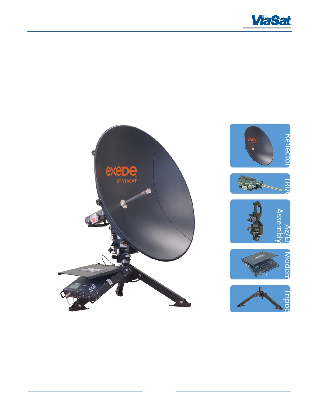
1 INTRODUCTION
The ViaSat SurfBeam 2 (SB2) Pro Portable Terminal (Figure 1-1) provides portable and quickly deployable, high-speed
internet and network connections in remote regions. The unit supports live video, file transfer, internet browsing and
more. It functions across multiple operating systems and hardware platforms to support various applications (e.g.,
Skype, Google, Yahoo, etc.).
The SB2 Pro Portable Terminal is a true “Go Anywhere” device designed to meet the exacting needs of first responders,
newsgathering, and other professional applications. With its compact size, easy setup, ruggedized hardware (built to
MIL-STD-810 specifications), and support of both AC and DC power, the unit can be deployed in any location.
The Pro Portable Terminal’s design allows it to be setup, configured, and function in harsh environments (high winds,
rain, snow, and dust). Items such as a weatherproof modem (with a built in four port Ethernet router) and GPS allow
for easy satellite acquisition and quick service connection.
Figure 1-1: SurfBeam 2 Pro Portable
Page 8
SurfBeam® 2 Pro Portable Terminal Operations Guide
© 2014 ViaSat, Inc.
Page 2-1
All Rights Reserved
1172964, Rev. 002
ViaSat Proprietary Information
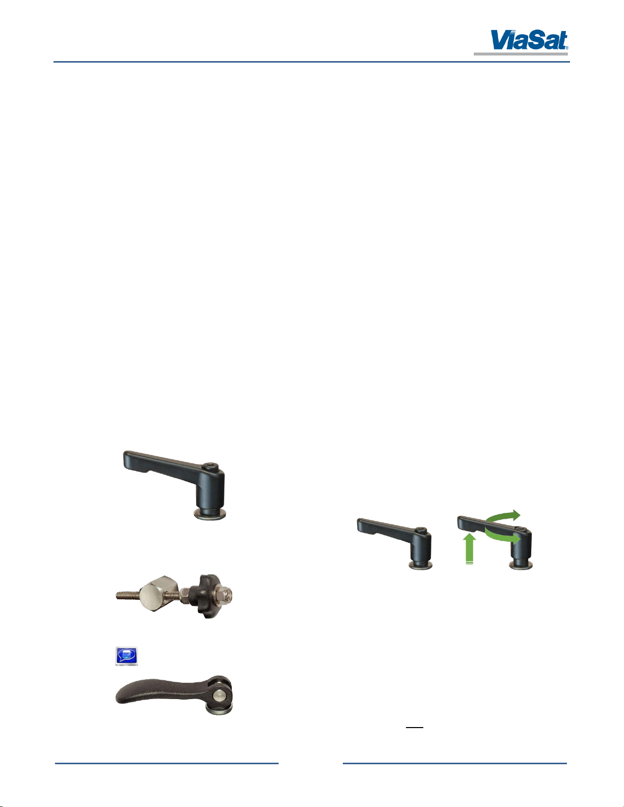
Lever Fastener
These levers are to be hand tightened, using the handle as a
lever to tighten.
NOTE: Lifting up on the lever allows for repositioning the
angle of the lever’s handle (left or right).
Knob Fastener /
Fine Tuning Knob
These knobs are to be hand tightened, using a twisting
motion.
NOTE: The Lever Fastener shown below is used on first generation Pro Portables. These units require
additional care when using this fastener (see below).
Lever Fastener
(older models)
These levers are to be hand tightened, using the handle as a
lever to tighten.
NOTE: Even though these levers appear to be cam-locking
levers, they are NOT to be used this way.
2 TERMINAL SETUP AND TEARDOWN
The SurfBeam 2 Pro Portable Terminal can be deployed in just about any desired location. To ensure optimal
performance, all the installer must do is identify a stable deployment location with an unobstructed view of the sky
and properly assemble the unit.
2.1 Site Survey
Conducting a site survey will ensure that the user maximize their opportunity for a successful connection to the
Satellite Network. When determining a location, keep the following in mind:
Clear View of the Sky – The unit needs a clear view of the sky. (Using a dish pointing application for your
smartphone may assist in deploying the terminal; however, such a program is not required.)
Distance from Objects (i.e., buildings, bushes, trees, hills/mountains, etc.) – The placement of the unit should
have a minimum 2-to-1 distance-to-height ratio between it and nearby objects. For example, an object
20ft tall requires a distance of 40ft or greater, 30ft tall requires 60ft, etc.
Ground Cover – The unit needs to be deployed on stable, flat ground; however, using the Tripods legs and level,
a user can adapt the unit to slopes of varying degrees.
Securing the Unit – The unit require the use of ballast (i.e., a 10 lbs. sandbag per Tripod leg) to secure it to the
ground in case of high winds. In the event the 10 lbs. ballast is insufficient to maintain stability,
discontinue use and secure the system by either disassembling and repacking the system or moving the
assemble unit into a sheltered area.
Operating Precautions – The unit needs a maintained 10ft safety perimeter to mitigate potential RF exposure on
uncontrolled general populations.
2.2 Fastening System
The Pro Portable uses two types of devices to fasten adjustment points. It is critical that the user tighten these
fasteners using the following methods.
Page 9
SurfBeam® 2 Pro Portable Terminal Operations Guide
© 2014 ViaSat, Inc.
Page 2-2
All Rights Reserved
1172964, Rev. 002
ViaSat Proprietary Information
CAUTION: Proper Electrostatic Discharge (ESD) precautions shall be maintained when handling
equipment.
NOTE: If the container is damaged, open the container in the presence of the shipping carrier agent if
possible. If damage is found after the equipment is unpacked, retain the container and packing
materials for inspection. This is important if a damage claim must be filed.
CAUTION: Do not attempt to operate the equipment if major damage is found. In the event
questionable damage (major or otherwise) is identified, contact ViaSat, Inc. for support.
CAUTION: Proper ESD precautions shall be maintained when handling equipment.
CAUTION: Care must be taken when handling the antenna to prevent damage to the unprotected
Transmit Receive Integrated Assembly (TRIA), modem, semi-rigid cables, and wire bundle.
CAUTION: Keep all connector covers on the units until ready to install. This will keep units clean from
foreign debris.
CAUTION: Care must be taken to prevent the cables from being crushed or bent when installing the
Antenna onto its mounting position.
CAUTION: Care must be taken when handling the antenna to prevent damage to the parabolic reflector,
feed, flexible cables, or any other antenna components.
CAUTION: The reflector should only be moved in azimuth and elevation by hand, using a slow deliberate
motion. The reflector should never be moved quickly or jerked.
CAUTION: Before applying power, clear the area around the antenna.
CAUTION: Before connecting the interface cables to either the modem or the antenna, make sure the
modem power is off. DC power is present on the Receive and Transmit Inter-Facility Link cables when
power is on.
CAUTION: Always lift Antenna by its base to avoid bending brackets and causing misalignment of
precision assemblies.
2.3 Receiving, Unpacking, and Assembly
2.3.1 Receiving
2.3.1.1 Unpacking and Inspection
To unpack and inspect the equipment, perform the following procedures:
Inspect the shipping container for damage before unpacking the equipment. Document any obvious dents,
punctures, or other irregularities on the shipping form.
Open the container and remove the packing material on top of the equipment.
While performing the Assembly process, inspect the equipment for external damage including dents and
scratches.
Save the packing material and containers for reshipment and/or servicing.
2.3.1.2 Handling and Precautions
Page 10
SurfBeam® 2 Pro Portable Terminal Operations Guide
© 2014 ViaSat, Inc.
Page 2-3
All Rights Reserved
1172964, Rev. 002
ViaSat Proprietary Information
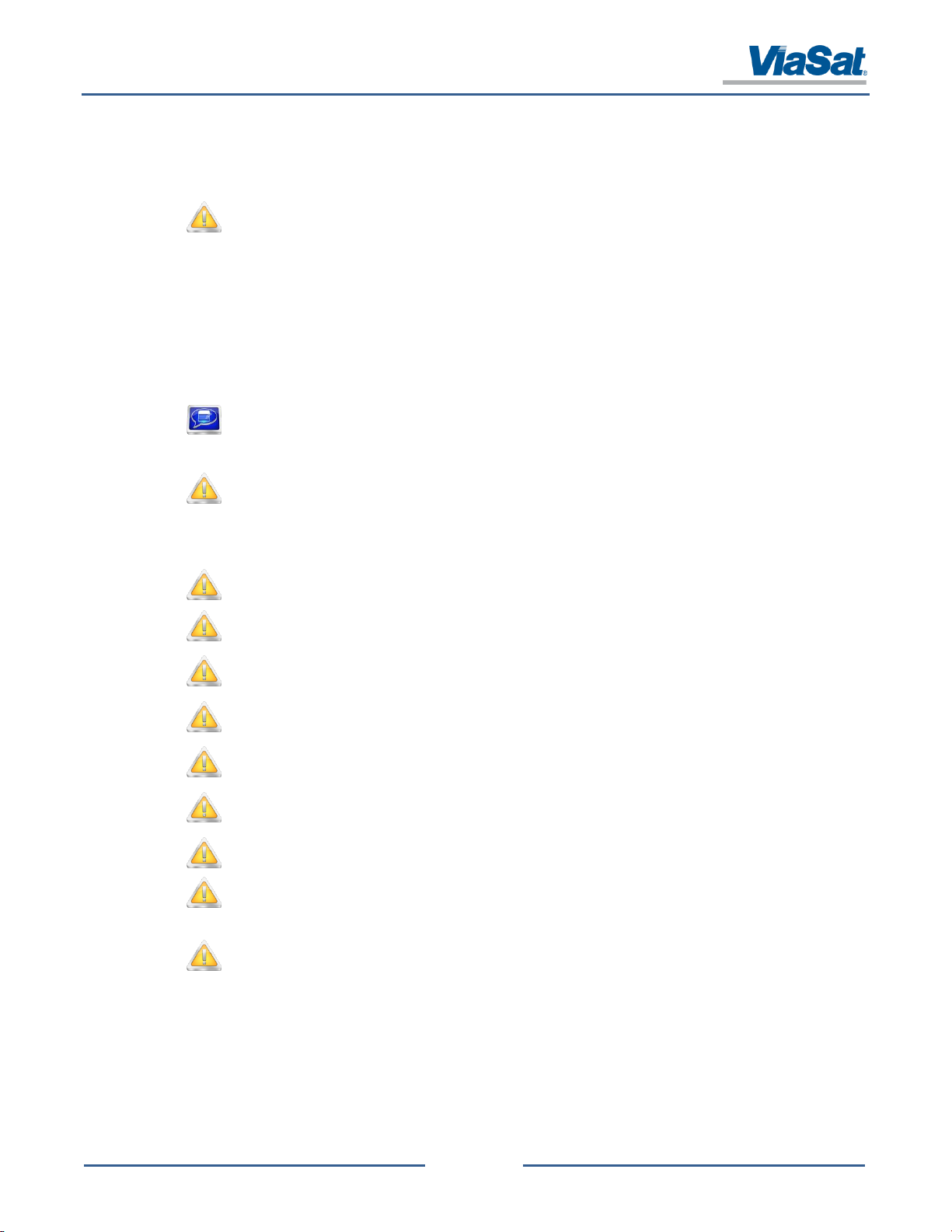
2.3.1.3 Antenna and Modem Handling Restrictions
Antenna Restrictions
Proper handling of the antenna is extremely important to prevent damage to it and its mechanical/electrical
components. The antenna shall only be carried by the Tripod by two or more individuals without the modem (using
the Azimuth/Elevation Assembly for stabilization) per the instructions provided in this manual. NEVER move or carry
the antenna by any part of the rotating antenna reflector, TRIA, or modem. Observe restrictions shown in Figure 2-1
for proper handling and moving of the antenna.
Figure 2-1: Antenna Transporting Restrictions
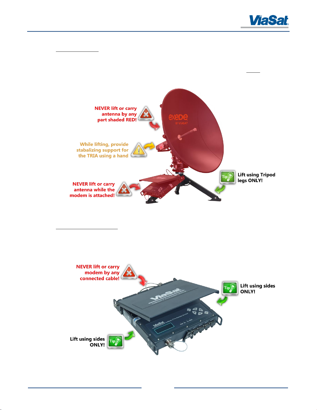
Modem Assembly Restrictions
Proper handling of the modem assembly is extremely important to prevent damage to it and its electrical components.
The assembly shall only be carried or moved by using two hands (one hand on each side) and never by any connected
cable. Observe the handling restrictions shown in Figure 2-2 for proper handling and transportation.
Figure 2-2: Modem Assembly Transporting Restrictions
Page 11
SurfBeam® 2 Pro Portable Terminal Operations Guide
© 2014 ViaSat, Inc.
Page 2-4
All Rights Reserved
1172964, Rev. 002
ViaSat Proprietary Information
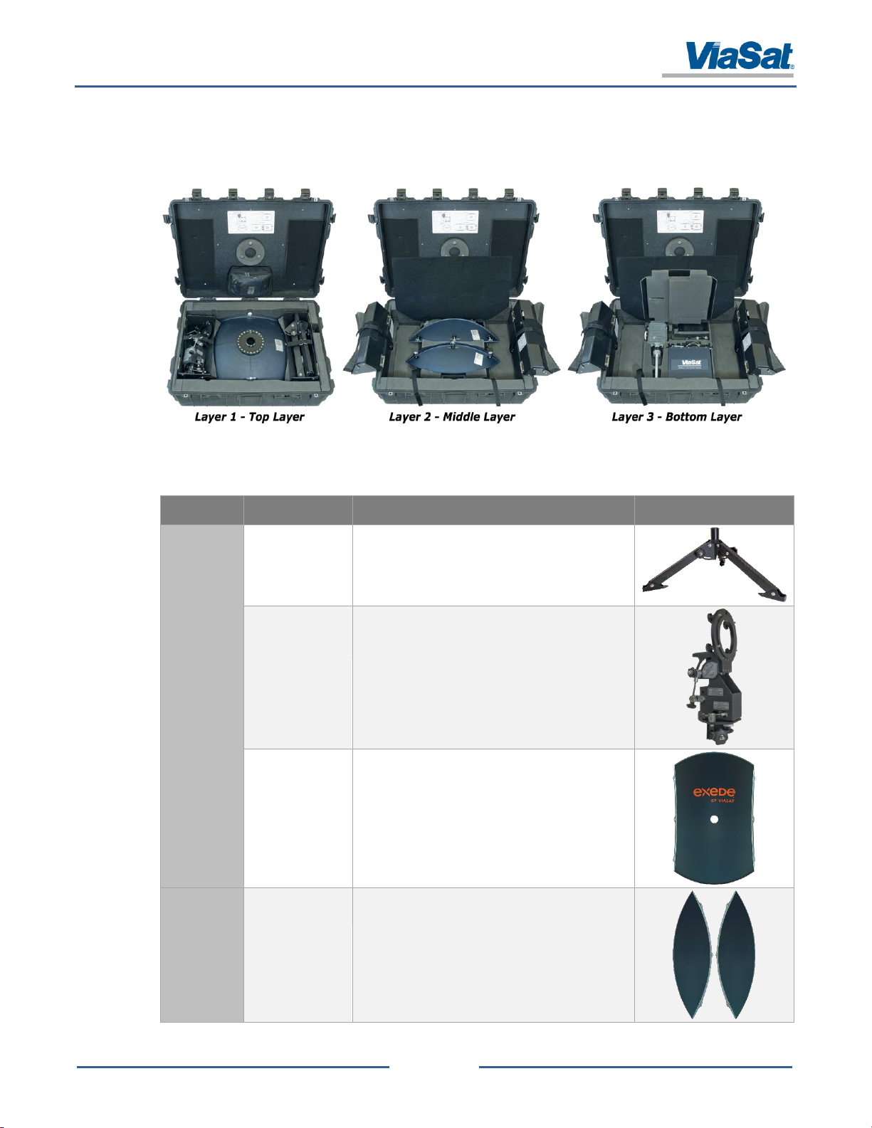
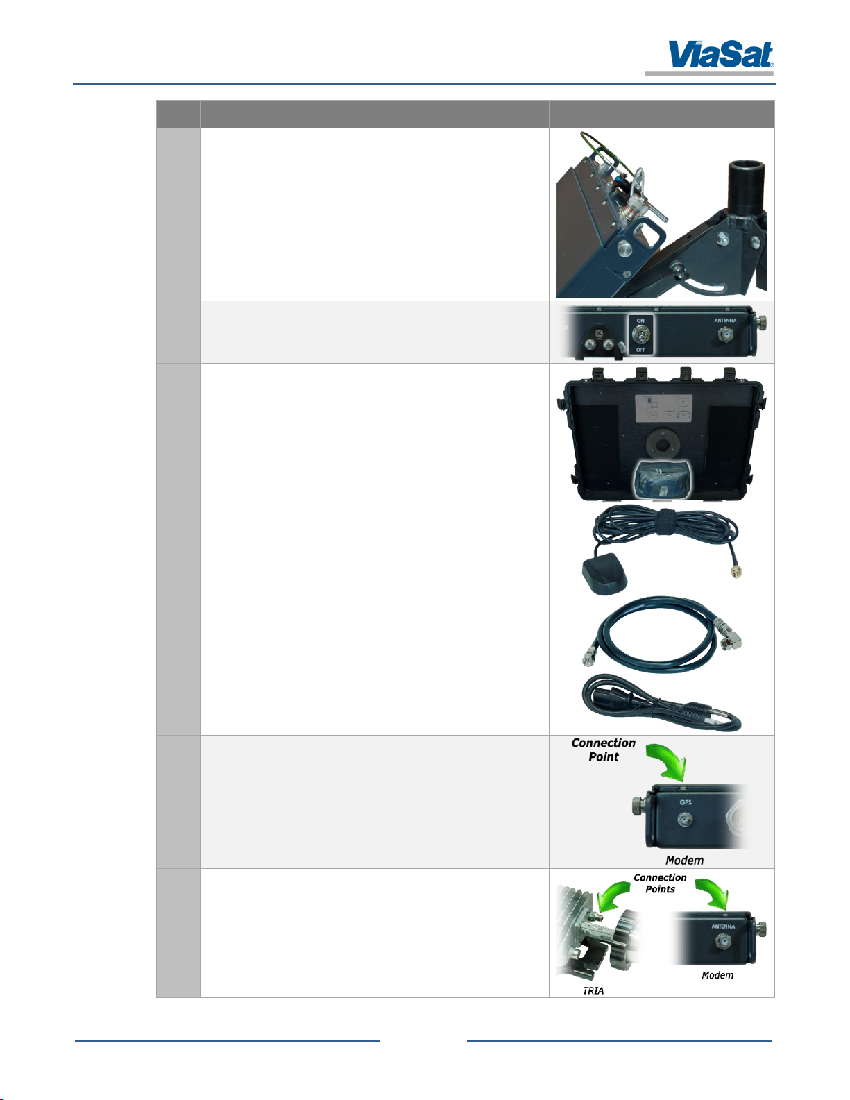
Layer
Component
Description
Image
Layer 1
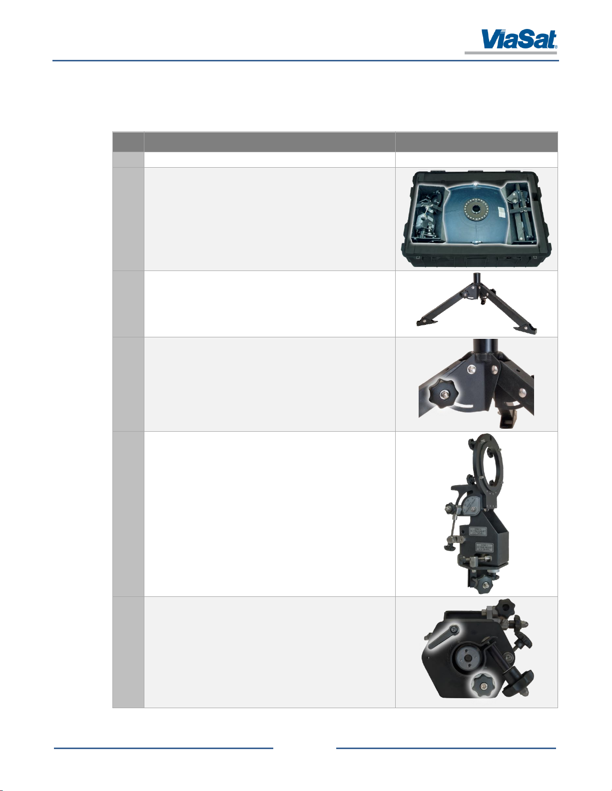
Tripod
The Tripod has three adjustable legs (with pivot
feet) that connected to center pole to which the
Azimuth/Elevation Assembly head connects.
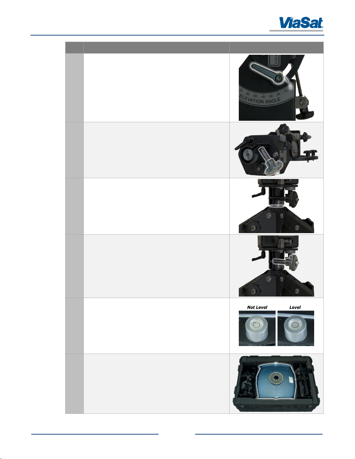
Azimuth (Az) /
Elevation (El)
Assembly
The head has four adjustment levers to point and
lock the assembly head once the fully assemble
unit has been pointed. This component mounts
atop the tripods center pole and provides a
platform base for the installation of the TRIA and
center reflector
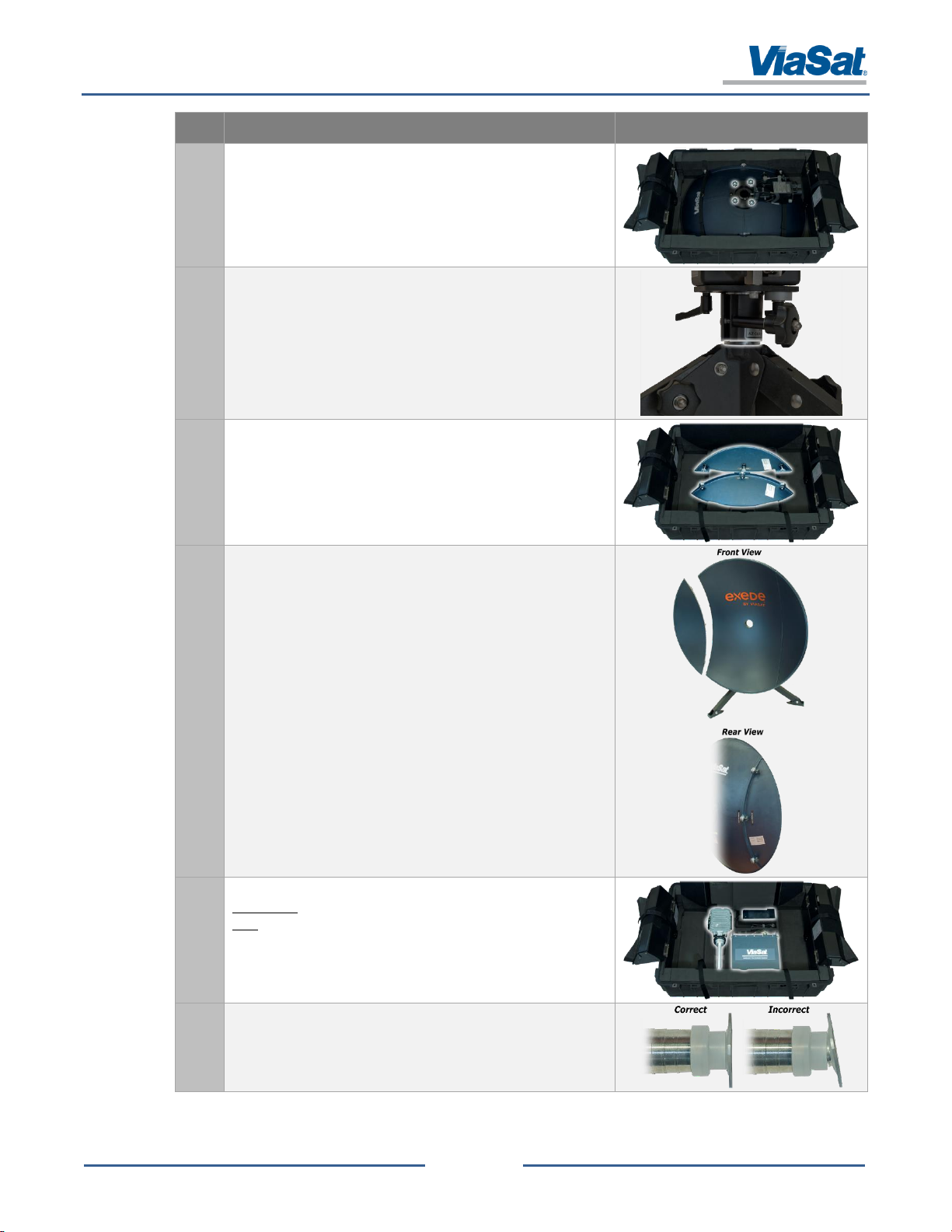
Center Reflector
The center reflector provides the middle piece of
the antenna dish and mounts to the
Azimuth/Elevation Assembly.
Layer 2
Edge Reflector
(x2)
The edge reflector provides the edge piece of the
antenna dish and mounts to either side of the
center reflector. These two parts are
interchangeable.
2.3.2 Unpacking
The Pro Portable components come in a rugged, protective transit case with three layers and an attached accessory
bag (Figure 2-3). Each layer and the bag provide a group of components (Table 2-1) that need to be assemble before
moving on in the assembly process.
Figure 2-3: Component Assembly Layers
Table 2-1: Component Assembly List
Page 12

SurfBeam® 2 Pro Portable Terminal Operations Guide
© 2014 ViaSat, Inc.
Page 2-5
All Rights Reserved
1172964, Rev. 002
ViaSat Proprietary Information
Layer
Component
Description
Image
Layer 3
Modem
Assembly
The modem assembly is a rectangular shaped box
with a protective lid, an LCD screen, navigation
buttons, 4 Ethernet ports, 4 round connector
ports, and an ON/OFF switch. The component
connects the host computer with the network, via
the TRIA and antenna dish.
TRIA
The TRIA is the receiver/transmitter that convers
signals between L-Band and Ka-Band.
Power Supply
Brick
The power supply brick provides consistent power
output at 24V, 9.2A, 221W max.
Accessory
Bag
GPS
The GPS is a magnetic “computer-mouse” shaped
device attached to a RG-174 15’ cable.
Coax Cable
The Coax cable is a 3’ RG-6 F-Type (m) to F-Type
(m), 75 Ohms, copper core cable that connects the
modem and TRIA.
(The cable is rated for use at frequencies up to 3ghz, a DC
resistance less than 4.5 Ohms, a Tx IF loss of less than
15dB for 1800 to 2300MHz, and a Rx IF loss less than
10dB for 300 to 800MHz.)
Ethernet Cable
The Ethernet cable is a 5’ RJ-45 CAT-5 cable.
TRIA Splash Plate
The Splash Plate is a replacement unit should the
one installed on the TRIA be damaged or lost.
Power Cable
The Power cable for the Power Supply Brick is
common three-wire cable.
90° Coax
Connector
The 90° coax connector is designed to modify a
straight RG6 F-type cable connection.
Page 13
SurfBeam® 2 Pro Portable Terminal Operations Guide
© 2014 ViaSat, Inc.
Page 2-6
All Rights Reserved
1172964, Rev. 002
ViaSat Proprietary Information
Step
Action
Image
1.
Perform a site survey to locate your unit’s deployment location.
-
2.
Open the transit case on a flat surface to see the top layer of the
case’s components.
Tripod
Azimuth/Elevation Assembly
Center Reflector
3.
Remove the Tripod from the pocket on the right side of the case
and loosen all knobs to arrange each leg in its out-most position.
4.
Tighten each knob (x3) to lock the Tripod’s legs and position the
Tripod with one leg pointing north.
5.
Remove the Azimuth/Elevation Assembly from the pocket on the
left side of the case.
6.
Looking at the base of the Assembly, loosen the Azimuth lever
and knob.
2.3.3 Assembling
After performing the site survey (review section 2.1 before starting the process below), the user can now unpack,
assemble, and deploy the unit. Table 2-2 provides the instructions on this process.
Table 2-2: Unpack and Assembly Process
Page 14

SurfBeam® 2 Pro Portable Terminal Operations Guide
© 2014 ViaSat, Inc.
Page 2-7
All Rights Reserved
1172964, Rev. 002
ViaSat Proprietary Information
Step
Action
Image
7.
Verify that the Assembly base-plate and tower edges are
approximately parallel.
If they are not, rotate the Azimuth Fine Adjusting knob
until the two edges become parallel.
8.
Turn the Azimuth lever until tightened (leaving the Azimuth knob
loose).
9.
Looking at the back of the Assembly, loosen the Elevation lever
(left highlight) and knob (right highlight).
10.
Verify that the Assembly top-plate has an Elevation angle of 0°.
If it does not, rotate the top-plate to its bottom position
and rotate the Elevation Fine Adjusting knob until the
line on the top-plate lines up with the 0° marker on the
tower.
Page 15
SurfBeam® 2 Pro Portable Terminal Operations Guide
© 2014 ViaSat, Inc.
Page 2-8
All Rights Reserved
1172964, Rev. 002
ViaSat Proprietary Information
Step
Action
Image
11.
Turn the Elevation lever until tightened (leaving the Elevation
knob loose).
12.
Loosen Assembly Post knob.
13.
Slide the Assembly onto the Tripod’s post and rotate it to ensure
proper seating (revealing a 1/4-inch gap between the Assembly’s
collar bottom and the top of the Tripod’s legs).
14.
Tighten the Assembly Post knob.
15.
Loosening/tightening the knobs on the Tripod’s legs and using
the leveling bubble on the Assembly base-plate, make the
appropriate adjustments to get the leveling bubble to show
inside the black circle.
NOTE: It is not necessary to get the bubble to lineup exactly
within the back circle. Approximately 90% or more of the bubble
within the circle should be enough.
16.
Remove the Assembly, go to the transit case, and fold open the
two pockets that held the Assembly and Tripod to gain access to
the Center Reflector.
Page 16
SurfBeam® 2 Pro Portable Terminal Operations Guide
© 2014 ViaSat, Inc.
Page 2-9
All Rights Reserved
1172964, Rev. 002
ViaSat Proprietary Information
Step
Action
Image
17.
Mount the Assembly to the back of the Reflector using the four
attached screws (hand-tighten these screws only), where the top
of the Assembly points to the ViaSat logo.
18.
Remove the Reflector and Assembly from the case, and slide the
Assembly onto the Tripod’s post and rotate it to ensure proper
seating (revealing a 1/4-inch gap between the Assembly’s collar
bottom and the top of the Tripod’s legs).
19.
At the transit case, fold back the layer two felt divider and
remove one of the Edge Reflectors.
20.
Attach the Edge reflectors to each side of the Center Reflector
(one at a time) using the attached screws (hand-tighten these
screws only).
NOTE: For each Edge reflector, start by tightening the middle
screw first and then tighten the two outer screws.
21.
At the transit case, fold back the layer two and three dividers and
CAREFULLY remove the TRIA (lifting the TRIA by the housing and
NOT the Feedhorn).
22.
Visually inspect the TRIA to ensure no damage has occurred and
that the Splash Plate is properly seated on the Feedhorn.
Page 17

SurfBeam® 2 Pro Portable Terminal Operations Guide
© 2014 ViaSat, Inc.
Page 2-10
All Rights Reserved
1172964, Rev. 002
ViaSat Proprietary Information
Step
Action
Image
23.
With the TRIA placed on a stable surface, remove the 90° Coax
Connector from the Accessory Bag and connect it to the TX/RX
port on the TRIA.
NOTE: Ensure that the 90° connector is firmly attached (hand
tightened only).
NOTE: This connector can be installed later as shown in Step 31.
24.
Holding the sides of the TRIA housing and from behind the Center
Reflector, CAREFULLY insert the Feedhorn through the reflector
hole until the base of the Feedhorn and TRIA alignment slots
contact the reflector hole and Assembly top-plate alignment
posts.
25.
Place one hand on the back of the TRIA housing and another on
the Assembly tower. Gently push and wiggle the TRIA housing
until it snaps into place.
26.
Hand tighten the large Collar Ring located between the TRIA
housing and reflector to connect the two components. Visually
inspect that the TRIA’s Feedhorn base is flush to the inside of the
Center Reflector.
27.
Visually inspect the TRIA to ensure no damage has occurred and
that the Splash Plate is properly seated on the Feedhorn.
28.
At the transit case, fold back the layer two and three dividers and
CAREFULLY remove the modem assembly.
Page 18
SurfBeam® 2 Pro Portable Terminal Operations Guide
© 2014 ViaSat, Inc.
Page 2-11
All Rights Reserved
1172964, Rev. 002
ViaSat Proprietary Information
Step
Action
Image
29.
Attach the modem assembly to the Tripod leg pointing north and
insert the quick-release pin (pressing the pin’s blue button)
through the assembly mounting plate (locate at the back) and the
hole that goes completely through the top and bottom of the leg.
30.
Verify that the modem’s power switch is turned OFF.
31.
At the transit case, locate the pouch attached to the inside of the
case’s lid and remove the GPS (with cable), 3ft RG6 Coax cable,
and power cable.
NOTE: Ensure that the 90° connector is firmly attached to the 3ft
RG-6 Coax cable if not already installed on the TRIA (hand
tightened only) as shown in Step 21.
32.
Connect the end of the GPS cable to the “GPS” port on the back
of the modem and place the other end (with the GPS) at least 5ft
way.
33.
Connect one end of the 3ft RG6 Coax cable to the “Antenna” port
on the back of the modem assembly and connect the other end
with the 90° connector fitting to the “TX” port on the TRIA.
Page 19
SurfBeam® 2 Pro Portable Terminal Operations Guide
© 2014 ViaSat, Inc.
Page 2-12
All Rights Reserved
1172964, Rev. 002
ViaSat Proprietary Information
Step
Action
Image
34.
At the transit case, fold back the layer two and three dividers and
remove the power supply brick.
35.
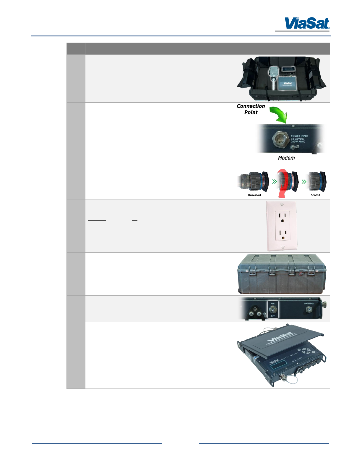
Connect the power cable to the power supply brick and twist the
connector onto the “Power Input” port on the back of the
modem assembly.
Twist the cap until it stops clicking and the blue ring on
the cap covers the red ring on the modem port.
36.
Plug the end of the power cable into a grounded AC power
outlet.
DO NOT connect to ungrounded power sources, as this will
severely damage the unit.
37.
Place any remaining storage bags and/or parts back into the
transit case and close/latch the lid.
38.
Flip the power switch located on the back of the modem
assembly from the OFF position (down) to the ON position (up).
39.
Open the lid of the modem assembly and use the tightening
screws on either side to lock it in the desired position.
Page 20

SurfBeam® 2 Pro Portable Terminal Operations Guide
© 2014 ViaSat, Inc.
Page 2-13
All Rights Reserved
1172964, Rev. 002
ViaSat Proprietary Information
Step
Action
Image
1.
Power down the modem assembly using the on/off switch.
2.
Unplug the all the cables from the modem assembly, TRIA, and
power brick, and place them back into the pouch located on the
underside of the case lid.
3.
Hold down the Modem push-pin, remove it from Tripod leg, and
place the modem and power brick in its place on the bottom
layer of the case.
4.
Re-attach plug dust covers on the modem assembly. Place the
assembly and power brick in its place on the bottom layer tray of
the case.
5.
Fold the tray’s cover down to cover the equipment and using the
two straps located on the tray’s handle side: (1) loop the strap
through the metal ring, (2) pull the strap tight, and (3) lay it back
over itself so that the Velcro attaches.
NOTE: Pervious versions of the Pro Portable case did not have
restraining straps. If there are no straps, disregard this step.
2.4 Disassemble and Repack
The SurfBeam 2 Pro Portable Terminal will need to be stowed after each use. Table 2-3 provides the instructions on
this process.
Table 2-3: Disassembly and Repacking Process
Page 21

SurfBeam® 2 Pro Portable Terminal Operations Guide
© 2014 ViaSat, Inc.
Page 2-14
All Rights Reserved
1172964, Rev. 002
ViaSat Proprietary Information
Step
Action
Image
6.
Loosen the Elevation lever and knob to lower the TRIA and
Reflector to a level position, and then re-tighten them for
stability.
7.
Unscrew collar, remove the TRIA from the Reflector, and place it
carefully in its designated location on the bottom layer of the
case.
NOTE: If the splash plate falls off the TRIA, put it back on.
8.
With the TRIA placed on a stable surface, remove the 90° Coax
Connector from the Accessory Bag and connect it to the TX/RX
port on the TRIA.
NOTE: Ensure that the 90° connector is firmly attached (hand
tightened only).
9.
Unscrew and detach the Edge Reflectors (pulling/wiggling) and
place them back into the case.
NOTE: Ensure the protective felt divider covers the top of the edge
reflectors after being placed in the case.
Page 22

SurfBeam® 2 Pro Portable Terminal Operations Guide
© 2014 ViaSat, Inc.
Page 2-15
All Rights Reserved
1172964, Rev. 002
ViaSat Proprietary Information
Step
Action
Image
10.
Remove the combination Center Reflector-AZ/EL unit from the
Tripod and place it in the center of the case.
NOTE: Keep the side pockets open outward before placing the
Center Reflector in the case.
11.
Remove the AZ/EL assembly from the Center Reflector by
loosening the four connecting screws.
12.
Using the four straps (two from the hinge side and two from the
opposing side): (1) loop the strap through the metal ring, (2) pull
the strap tight, and (3) lay it back over itself so that the Velcro
attaches.
NOTE: Pervious versions of the Pro Portable case did not have
restraining straps. If there are no straps, disregard this step.
13.
Then loosen the Elevation knob (beside the AZ/EL Assembly’s
“Fine Adjust Preset” label) and move the elevation back to “0”,
and re-tighten.
14.
Looking at the base of the Assembly, loosen the Azimuth lever
and knob.
15.
Verify that the Assembly base-plate and tower edges are
approximately parallel.
If they are not, rotate the Azimuth Fine Adjusting knob
until the two edges become parallel.
Page 23

SurfBeam® 2 Pro Portable Terminal Operations Guide
© 2014 ViaSat, Inc.
Page 2-16
All Rights Reserved
1172964, Rev. 002
ViaSat Proprietary Information
Step
Action
Image
16.
Turn the Azimuth lever until tightened (leaving the Azimuth knob
loose).
17.
Place the AZ/EL Assembly in the left pocket and lock down with
the inner most strap and then the outer most strap.
NOTE: Pervious versions of the Pro Portable case only had one
restraining strap. If there is only one, disregard the second
portion of this step and only attach the one strap.
18.
Loosen Tripod knobs, fold feet inward (insure that its feet have
the points pointing towards the inside), and tighten the levers.
19.
Place the Tripod in the right pocket and lock down with the inner
most strap and then the outer most strap.
NOTE: Pervious versions of the Pro Portable case only had one
restraining strap. If there is only one, disregard the second
portion of this step and only attach the one strap.
20.
Confirm that all cables are in the case pouch and zip it closed,
close the case top, and ensure the lid lock-down latches are
secure.
Page 24

SurfBeam® 2 Pro Portable Terminal Operations Guide
© 2014 ViaSat, Inc.
Page 3-1
All Rights Reserved
1172964, Rev. 002
ViaSat Proprietary Information
Tone Name
Description
Audio Example
Heartbeat
The Heartbeat tone indicates the TRIA is receiving power from the modem,
but is not pointed at a satellite it recognizes. This tone is the initial tone at
the beginning of the Point-and-Peak process. It is only heard when the
TRIA pointed outside of the frequency range of a Beam.
Ring-Ring
The Ring-Ring tone defines the “edge” of the Satellite Beam and sounds
like an old style telephone. The tone is only heard when entering the
Beam. Therefore, to find both the right and left edges of the Beam, the
Installer will sweep to the left, then sweep back to the right. This allows
the modem to learn all the frequencies available in the beam.
Single Short
Beep
The Single Short Beep tone is a ‘confirmation’ that the alignment process
has found the correct satellite. This tone occurs just after Ring-Ring tone
defines the edge of the Satellite Beam.
The Single Short Beep is always heard in combination with the Ring-Ring.
Low/Slow and
High/Fast
The Low/Slow and High/Fast tones are a set of tones that grade the
frequencies being learned by the modem. This allows the Installer to
hear/identify the center and the edges of the Beam.
High/Steady
The High/Steady tone indicates the center of the currently known
frequency set. To find the correct center, the user must complete the
entire Point-and-Peak process. When the final Center Point Frequency is
found, the antenna will pass.
Beep-Bop
The Beep-Bop tone indicates two modem states:
When the TRIA locates a satellite with Ka-Band frequencies that the
modem does not recognize
When the modem has reset during a re-Pointing process.
3 TERMINAL SATELLITE ALIGNING
3.1 Pointing and Peaking Tones
The Pro Portable incorporates a Point-and-Peak process that uses digital tones for acquiring a satellite’s signal. These
tones assist a user in identifying the peak azimuth and elevation angles to maximize connectivity (Table 3-1).
Table 3-1: Pointing and Peaking Tone List
Page 25

SurfBeam® 2 Pro Portable Terminal Operations Guide
© 2014 ViaSat, Inc.
Page 3-2
All Rights Reserved
1172964, Rev. 002
ViaSat Proprietary Information
Step
Action
Image
1.
After turning on the modem, the LED display shows the Start
screen. The LED display is controlled by the Up/Down,
Right/Left, ESC, and ENT buttons located to the right of the LED
display. While the Start screen is displayed, press the ENT button
to access the Main Menu screen.
2.
On the Main Menu screen, use arrow keys to scroll to “→ 1.
Pointing” menu item and press ENT button to access the Location
screen.
NOTE: Pressing the ENT button will select whatever option that’s
displayed on the middle line and identified by “→”.
NOTE: If the display starts showing a checkerboard pattern, just
press any of the four Arrow Keys to continue. The
checkerboard is a screen saver.
3.
When the Location screen opens, wait for values to display in the
LAT and LON fields (the display will show a series of question
marks “?” while waiting to get a GPS fix).
This process may take several minutes to complete; however, if
more than 5 minutes have elapsed without values appearing, try
moving the GPS puck to another location.
NOTE: If you are going to relocate the modem after Pointing,
write down the GPS’s latitude and longitude location so you
can manually input it later.
4.
Use arrow keys to scroll to “→ Press ENT to Cont.” menu item
and press ENT button and continue with section 3.3, Baseline
Elevation and Azimuth Setup.
3.2 Modem Setup
After performing the assembly of the Pro Portable Terminal (complete section 2.2 before starting the process below),
the user can now setup the modem. Table 3-2 provides the instructions on this process, while section 4.1 provides
additional details regarding the modem’s LCD screen, LEDs, and buttons.
Table 3-2: Modem Setup Process
Page 26

SurfBeam® 2 Pro Portable Terminal Operations Guide
© 2014 ViaSat, Inc.
Page 3-3
All Rights Reserved
1172964, Rev. 002
ViaSat Proprietary Information
Step
Action
Image
1.
Once the GPS is fixed, press the ENT button to display the
Elevation/ Azimuth status screen.
The Rx LED light will be flashing and the heartbeat tone can be
heard from the TRIA. This indicates that the TRIA is in Install
Mode and ready to begin vertically sweeping the antenna to
locate the satellite.
2.
While supporting the back of the TRIA:
Loosen the “Lock EL Angle” lever (left side of the AZ/EL
Assembly)
Loosen the “Internal Elevation” knob (beside the AZ/EL
Assembly’s “Fine Adjust Preset” label).
3.
Using the Inclinometer on the side of the TRIA manually set the
reflector elevation to the “EL” value shown on the “Status” screen
(see Step 1) and tighten the internal elevation knob.
NOTE: If done correctly, the Inclinometer and “Fine Adjust Preset”
values should approximately match (i.e., 40° on the
Inclinometer and 40° on the “Fine Adjust Preset”).
4.
Using the “EL Fine Adjust” knob, raise or lower the TRIA angle to
dial-in the elevation reading on the Inclinometer to equal the “EL”
value shown on the “Status” screen.
NOTE: This may take many turns to make a fine movement.
3.3 Baseline Elevation and Azimuth Setup
After performing the assembly of the Pro Portable Terminal (complete sections 2.2 and 3.2 before starting the process
below), the user can now set the unit’s baseline elevation and azimuth. Table 3-3 provides the instructions on this
process.
Table 3-3: Baseline Elevation and Azimuth Setup Process
Page 27

SurfBeam® 2 Pro Portable Terminal Operations Guide
© 2014 ViaSat, Inc.
Page 3-4
All Rights Reserved
1172964, Rev. 002
ViaSat Proprietary Information
Step
Action
Image
5.
Loosen the “AZ Course Adjustment” knob and SLOWLY swing the
Azimuth/Elevation Assembly to the left and right to identify the
full range where the modem emits a “Ring-Ring” tone.
NOTE: If you don’t hear a “Ring-Ring” tone, use the “EL Fine
Adjust” knob to raise or lower the TRIA angle (a degree at a
time) until the you hear the tone.
6.
After Identifying the horizontal range where the modem emits a
“Ring-Ring” tone, rotate the Assembly back across that range
until you hear a “Short Beep” tone and tighten the “AZ Course
Adjustment” lever.
The “Short Beep” tone will change to either a “Low/Slow” tone or
a “High/Fast” tone, indicating the unit is ready for fine-tuning.
NOTE: If you continue to hear “Short Beep” tone and NOT a
“Low/Slow” or a “High/Fast” tone, use the “EL Fine Adjust”
knob to raise or lower the TRIA angle (a degree at a time) until
the you hear one of the two tones.
Page 28

SurfBeam® 2 Pro Portable Terminal Operations Guide
© 2014 ViaSat, Inc.
Page 3-5
All Rights Reserved
1172964, Rev. 002
ViaSat Proprietary Information
Step
Action
Image
1.
Loosen the “Lock AZ Angle” knob (left highlight) and the “Lock AZ
Angle” knob (right highlight) on the bottom of the base plate.
NOTE: Leave the “Lock AZ Angle” knob just tight enough to allow
the azimuth to move.
2.
Using the “AZ Fine Adjust” knob, horizontally adjust the azimuth:
a. Left until the tone changes from a “Low/Slow” tone to NO
tone.
b. Maintaining a consistent speed, start turning the adjustment
knob right while counting until you hear the tone go from:
No Tone → Low/Slow → High/Fast → Low/Slow → No
Tone
c. Divide the ending count number by 2 and using the same
speed, turn the knob right until you reach the halfway mark.
No Tone → Low/Slow → High/Fast
NOTE: The modem screen’s “SNR” and “Peak” dB numbers will
change during this process, and the screen will report a
“Status” as “Complete” even though the fine-tuning process in
not complete.
3.
Tighten the two “Lock AZ Angle” knobs on the base plate so the
antenna has no movement left or right.
NOTE: If you lose the tone while tightening; loosen them and
repeat the above steps.
3.4 Fine-tuning Azimuth and Elevation Setup
After performing the assembly of the Pro Portable Terminal (complete sections 2.2, 3.2, and 3.3 before starting the
process below), the user can now fine-tune the unit’s azimuth and elevation. Table 3-4 provides the instructions on
this process.
Table 3-4: Fine-tuning Azimuth and Elevation Setup Process
Page 29

SurfBeam® 2 Pro Portable Terminal Operations Guide
© 2014 ViaSat, Inc.
Page 3-6
All Rights Reserved
1172964, Rev. 002
ViaSat Proprietary Information
Step
Action
Image
4.
Using the “EL Fine Adjust” knob, vertically adjust the elevation:
a. Up until the tone changes from a “Low/Slow” tone to NO
tone.
b. Maintaining a consistent speed, start turning the adjustment
knob down while counting until you hear the tone go from:
No Tone → Low/Slow → High/Fast → Low/Slow → No Tone
c. Divide the ending count number by 2 and using the same
speed, turn the knob up until you reach the halfway mark.
No Tone → Low/Slow → High/Fast
NOTE: The modem screen’s “SNR” and “Peak” dB numbers will
change during this process, and the screen will report a
“Status” as “Complete” even though the fine-tuning process in
not complete.
5.
Tighten the “Lock EL Angle” lever so the antenna has no
movement up or down and verify that all other levers and knobs
are tight.
NOTE: If you lose the tone while tightening; loosen them and
repeat the above steps.
6.
Press the ENT button to begin the modem lock process. The LEDs
on the Modem will be flashing.
Rx LED will begin flashing and then go solid.
Tx LED will begin flashing and then go solid once it has
achieved modem lock.
ENET LED will begin flashing and then go solid.
NOTE: Normal operations will show the Rx, Tx, and ENET LEDs
flashing rapidly and may take several minute to accomplish.
7.
On the front of the modem, connect the CAT5 cable to the ENT1
port and the other end to a computer.
8.
Open a web browser window and type 192.168.100.1 into the
address bar and verify you can access the modem’s web
interface.
Page 30

SurfBeam® 2 Pro Portable Terminal Operations Guide
© 2014 ViaSat, Inc.
Page 3-7
All Rights Reserved
1172964, Rev. 002
ViaSat Proprietary Information
Step
Action
Image
1.
Record the GPS Latitude and Longitude while the modem is on
and connected to the antenna with the 3’ Coax cable.
2.
Power OFF the modem assembly.
3.
Disconnect the power supply cable from the “Power Input” port
on the back of the modem and the grounded AC power outlet.
4.
Place the modem assembly and GPS in the desired location, and
connect the Coax cable of the required length.
5.
Connect the power cable to the power supply brick and twist the
connector onto the “Power Input” port on the back of the
modem assembly.
a. Twist the cap until it stops clicking and the blue ring on the
cap covers the red ring on the modem port.
b. Plug the end of the power cable into a grounded AC power
outlet. (DO NOT connect to ungrounded power sources, as
this will severely damage the unit.)
6.
Power ON the modem assembly.
7.
After turning on the modem, the LED display shows the Start
screen. The LED display is controlled by the Up/Down,
Right/Left, ESC, and ENT buttons located to the right of the LED
display. While the Start screen is displayed, press the ENT button
to access the Main Menu screen.
8.
On the Main Menu screen, use arrow keys to scroll to “→ 2. GPS”
menu item and press ENT button.
NOTE: Pressing the ENT button will select whatever option’s
displayed on the middle line and identified by “→”.
NOTE: If the display shows a checkerboard pattern (a screen
saver), press any of the four Arrow Keys to continue..
3.5 Modem Relocation
After performing the assembly of the Pro Portable Terminal (complete sections 2.2, 3.2 through 3.4 before starting
the process below), the user can now relocate the modem. Table 3-5 provides the instructions on this process.
Table 3-5: Modem Relocation Process
Page 31

SurfBeam® 2 Pro Portable Terminal Operations Guide
© 2014 ViaSat, Inc.
Page 3-8
All Rights Reserved
1172964, Rev. 002
ViaSat Proprietary Information
Step
Action
Image
9.
On the GPS screen, use arrow keys to scroll to “→ 2. Manual
GPS” menu item and press ENT button.
10.
On the Manual GPS screen, use arrow keys to scroll to “→
Manual Mode” menu item and press right arrow button once to
turn ON (pressing the arrow twice will turn it OFF).
11.
On the Manual GPS screen, use arrow keys to scroll to “→ LAT”
menu item. Press right arrow button once to access the first “0”
field and use the up/down arrows to set the first number.
NOTE: After entering the first number, continue the same process
to set the remaining fields.
12.
After entering all required fields, press ENT to return to the “→
LAT” menu item and then use arrow keys to scroll to “→ LON”
menu item. Press right arrow button once to access the first “0”
field and use the up/down arrows to set the first number.
NOTE: After entering the first number, continue the same process
to set the remaining fields.
13.
After entering all required fields, press the ESC button twice.
NOTE: Pressing the ESC button will save the change.
14.
On the Main Menu screen, use arrow keys to scroll to “→ 1.
Pointing” menu item and press ENT button to access the Location
screen.
15.
When the Location screen opens, the values entered in the
previous steps will display in the LAT and LON fields.
16.
After verifying the LAT and LON fields, press the ENT button
twice.
NOTE: There is no reason to continue in the Pointing/Peaking
process, since those required steps were previously performed.
17.
On the front of the modem assembly, connect the CAT5 cable to
the ENT1 port and the other end to a computer.
18.
Open a web browser window and type 192.168.100.1 into the
address bar and verify you can access the modem’s web interface
by selecting “Modem” in the menu tree on the left.
Page 32

SurfBeam® 2 Pro Portable Terminal Operations Guide
© 2014 ViaSat, Inc.
Page 4-1
All Rights Reserved
1172964, Rev. 002
ViaSat Proprietary Information
4 TERMINAL OPERATIONS
The SurfBeam 2 Pro Portable modem uses an LCD screen and a web interface to provide valuable operational and
status information regarding the modem, antenna, and installation configuration. The following sections provide
details regarding accessing and navigating the modem’s LCD screen and web interface.
4.1 Modem Assembly LCD
The LCD screen on the modem assembly displays Pointing, GPS, Modem Status, DC Output, Help, Setting, and Volt
Status information, which the user navigates using the ESC, ENT, Left/Right Arrow, and Up/Down Arrow buttons on
the modems face plate (Figure 4-1).
Figure 4-1: Modem Assembly LCD Screen and User Interface
Figure 4-2 displays the modem assembly’s LCD menu navigation tree.
Figure 4-2: Modem Assembly LCD Menu Navigation Tree
Page 33

SurfBeam® 2 Pro Portable Terminal Operations Guide
© 2014 ViaSat, Inc.
Page 4-2
All Rights Reserved
1172964, Rev. 002
ViaSat Proprietary Information
4.2 Modem Web Interface
4.2.1 Accessing
To access the modem’s web interface, perform the following steps:
1. Configure a laptop for use on this same LAN as the modem by setting the laptop's network settings for DHCP.
In addition, the laptop can be connected directly to the modem ETH1 through ETH4 ports.
2. Launch a web browser on the Support PC.
3. At the web browser’s address field, enter the modem’s IP address (i.e., http://192.168.100.1) and press
<Enter>.
4.2.2 Navigation and Information
Once accessed, the web browser will open the modem’s “Home” page (Figure 4-3). From this page, the user can
access general information for the modem and TRIA configuration/status.
Figure 4-3: Modem Web Interface
Page 34

SurfBeam® 2 Pro Portable Terminal Operations Guide
© 2014 ViaSat, Inc.
Page 4-3
All Rights Reserved
1172964, Rev. 002
ViaSat Proprietary Information
Icon
Name
Description
Not Active (gray)
Beam is currently not being used. If all of the icons in the upper right corner
of the web page are gray, then the system has not locked onto a satellite
and the user must revisit section 3 to repoint and peak the system.
Active (purple, blue,
green,
orange)
Beam is currently being accessed. The color is used to identify which beam
is being accessed.
Function
Icon Set
Description
Forward Link
(First Icon)
Yellow = Indicates the modem is initiating a Forward Link connection.
“Scanning” means that the process has just initiated
“Syncing” means that the process is nearing completion
Green = Indicates the modem has established a Forward Link connection.
Return Link
(Second Icon)
Gray = Indicates that there is no Forward Link or that the Return Link is disabled
(several minute may pass before the icon changes color).
Yellow = Indicates the modem is initiating a Return Link connection (several minute
may pass before the icon changes color).
Green = Indicates the modem has established a Return Link connection.
Network Entry
(Third Icon)
Gray = Indicates that there is no Link connection or the Network Entry is disabled
(several minute may pass before the icon changes color).
Yellow = Indicates the modem is initiating a network connection (several minute may
pass before the icon changes color).
Green = Indicates the modem has established a network connection.
DHCP
(Fourth Icon)
Gray = Indicates that there is no Link connection or the DHCP acquisition is disabled
(several minute may pass before the icon changes color).
Yellow = Indicates the modem is requesting an IP address from a Gateway DHCP
(several minute may pass before the icon changes color).
Online
(All Icons)
Green = Indicates the modem is online and should connect to the internet; however, if
the system cannot connect to the internet:
Reboot the modem (may take multiple attempts)
Contact the NOC if the first several attempts did not correct the issue
Fault
Red = Indicates a fault has been detected or there is no communication’s link.
4.2.2.1 Web Page Common Features
There are common icons used throughout the web interface. These items help users quickly identify the current
modem, antenna, satellite, and communication statuses. Table 4-1 shows the color-coordinated operational beam
being used by the modem (displayed in the upper-right corner of all pages); while Table 4-2 lists the icons used to
show the system’s operating state (used on the Home, Modem, and Antenna pages).
Table 4-1: Operational Beam
Table 4-2: System Operating State
Page 35

SurfBeam® 2 Pro Portable Terminal Operations Guide
© 2014 ViaSat, Inc.
Page 4-4
All Rights Reserved
1172964, Rev. 002
ViaSat Proprietary Information
4.2.2.2 Home Page (Basic Status)
The Home page (Figure 4-4) provides general information on the status of the modem, Inter-Facility Link (IFL), and
antenna.
Figure 4-4: Modem Web Interface – Home Page
General
Modem: Displays the modem’s current operating state. Clicking on the “MODEM” label below the box displaying
the modem and the state icon, will navigate to the Modem page.
IFL: Displays the IFL’s current operating state. Clicking on the “IFL” label below the box displaying the IFL
connection and the state icon, will navigate to the IFL page.
TRIA: Displays the antenna’s current operating state. Clicking on the “TRIA” label below the box displaying the
antenna and the state icon, will navigate to the TRIA page.
Page 36

SurfBeam® 2 Pro Portable Terminal Operations Guide
© 2014 ViaSat, Inc.
Page 4-5
All Rights Reserved
1172964, Rev. 002
ViaSat Proprietary Information
4.2.2.3 Modem Page (Modem/IFL Cable Status)
The Modem page (Figure 4-5) provides general information on the status of the modem, Inter-Facility Link (IFL), and
antenna.
Figure 4-5: Modem Web Interface – Modem Page
Page 37

SurfBeam® 2 Pro Portable Terminal Operations Guide
© 2014 ViaSat, Inc.
Page 4-6
All Rights Reserved
1172964, Rev. 002
ViaSat Proprietary Information
Modem State
Modem: Displays the status of the modem (see section Table 4-2 regarding icon details).
Scanning: The modem is scanning or attempting to connect
Syncing: The modem is syncing with the network and antenna
Synced: The modem synced correctly
Ranging / Ranged: The modem is configuring operating ranges.
Network Entry: The modem is gaining access to the network
DHCP: The modem is configuring itself to connect with the network
Online: The modem is connected to the network and online
Online Time: Displays the duration of time the modem has been online.
General
Rx Power (dBm): Displays the modem’s power level.
Rx SNR (dB): Displays the Signal to Noise Ratio.
ODU Telemetry Status: Displays if the modem is collecting and transmitting data.
Cable Resistance (Ohms): Displays the amount of resistance the cable is producing (lower is better).
Cable Attenuation (dB): Displays the level of attenuation occurring between the modem and antenna.
Identification
IP Address: Displays the modem’s IP address.
Software Version: Displays the modem’s software version.
Serial Number: Displays the modem’s serial number.
IFL Type: Displays the IFL’s current operating state.
MAC Address: Displays the modem’s MAC address.
Hardware Version: Displays the modem’s hardware version.
Part Number: Displays the modem’s part number.
Ethernet Interface Statistics
Transmitted Packets: Displays the number of received IP packets.
Received Packets: Displays the number of received IP packets.
Loss of Sync Count: Counts the number of sync losses for the current connection.
Transmitted Bytes: Displays the number of bytes transmitted to the modem.
Received Bytes: Displays the number of bytes received by the modem.
Page 38

SurfBeam® 2 Pro Portable Terminal Operations Guide
© 2014 ViaSat, Inc.
Page 4-7
All Rights Reserved
1172964, Rev. 002
ViaSat Proprietary Information
4.2.2.4 TRIA Page (TRIA Status)
The TRIA page (Figure 4-6) provides general information on the status of the TRIA.
Figure 4-6: Modem Web Interface – TRIA Page
General
Tx IF Power (dBm): Displays the IF power for the TRIA.
Tx RF Power (dBm): Displays the RF power for the TRIA.
Temperature (°C): Displays the ATRIA’s operation temperature.
Diagnostics
Brownout and Blueout Mode Enabled: Displays “Yes” or “No” depending on system configuration.
TRIA Serial Number: Displays the TRIA’s serial number.
TRIA Firmware Version: Displays the TRIA’s firmware version.
Module Status
Bullfrog VG, Watchdog Timer, Tx/Rx PLL, Microprocessor, Cable Resistance, and Temperature: Displays or
depending on if the system has detected an issue.
Page 39

SurfBeam® 2 Pro Portable Terminal Operations Guide
© 2014 ViaSat, Inc.
Page 4-8
All Rights Reserved
1172964, Rev. 002
ViaSat Proprietary Information
4.3 Router Web Interface
4.3.1 Accessing
To access the router’s web interface, perform the following steps:
1. Configure a laptop for use on this same LAN as the modem by setting the laptop's network settings for DHCP.
In addition, the laptop can be connected directly to the modem ETH1 through ETH4 ports.
2. Launch a web browser on the Support PC.
3. At the web browser’s address field, enter the router’s IP address (i.e., http://192.168.100.1) and press Enter
4. The web browser will request a user authentication and password (Figure 4-7) (User Name: admin,
Password: admin).
4.3.2 Navigation and Information
Once accessed, the web browser will open the router’s “Home” page (Figure 4-8). From this page, the user can access
general information for the router configuration/status.
Figure 4-7: Router Web Interface Login Window
Figure 4-8: Router Web Interface
Page 40

SurfBeam® 2 Pro Portable Terminal Operations Guide
© 2014 ViaSat, Inc.
Page 4-9
All Rights Reserved
1172964, Rev. 002
ViaSat Proprietary Information
4.3.2.1 Status Tab
This tab provides information regarding the system, router, terminal, and modem. This section covers the “Home”
and “Router” pages, as selecting the “Terminal” or “Modem” will take the user to the appropriate “Modem Web
Interface” page.
4.3.2.1.1 System Status Page
The System Status page (Figure 4-9) provides general information on the status of the modem/router, Firmware
version, and connection activity.
Figure 4-9: Router Web Interface – System Status Page
Page 41

SurfBeam® 2 Pro Portable Terminal Operations Guide
© 2014 ViaSat, Inc.
Page 4-10
All Rights Reserved
1172964, Rev. 002
ViaSat Proprietary Information
4.3.2.1.2 Router Status Page
The Router Status page (Figure 4-10) provides general information on the status of the router’s WAN, DNS, LAN, DHCP,
and the router’s serial/part numbers.
Figure 4-10: Router Web Interface – Router Status Page
Page 42

SurfBeam® 2 Pro Portable Terminal Operations Guide
© 2014 ViaSat, Inc.
Page 4-11
All Rights Reserved
1172964, Rev. 002
ViaSat Proprietary Information
4.3.2.2 Setup Tab
This tab provides information regarding the WAN, LAN, and DHCP Clients. LAN and DHCP Clients, shown in the sidebar,
are the two most common and useful configuration pages that a user will access.
4.3.2.2.1 LAN Setup Page
The LAN Setup page (Figure 4-11) provides general information on the LAN configuration and the ability to configure
modem’s IP address and DHCP settings.
4.3.2.2.2 DHCP Setup Page
The DHCP Setup page (Figure 4-12) provides the ability to add static IP addresses and view general information on any
current configured static IP address.
Figure 4-11: Router Web Interface – LAN Setup Page
Figure 4-12: Router Web Interface – DHCP Setup Page
Page 43

SurfBeam® 2 Pro Portable Terminal Operations Guide
© 2014 ViaSat, Inc.
Page 4-12
All Rights Reserved
1172964, Rev. 002
ViaSat Proprietary Information
4.3.2.3 Network Tab
This tab provides information regarding the Port Forward, Range Forward, DMZ, Routes, and QoS.
4.3.2.3.1 Port Forwarding Page
The Port Forwarding page (Figure 4-13) provides general information and the ability to add/configure/remove ports
for Port Forwarding.
4.3.2.3.2 Range Forwarding Page
The Range Forwarding page (Figure 4-14) provides general information and the ability to add/configure/remove ports
for Range Forwarding.
Figure 4-13: Router Web Interface – Port Forwarding Page
Figure 4-14: Router Web Interface – Range Forwarding Page
Page 44

SurfBeam® 2 Pro Portable Terminal Operations Guide
© 2014 ViaSat, Inc.
Page 4-13
All Rights Reserved
1172964, Rev. 002
ViaSat Proprietary Information
4.3.2.3.3 DMZ Page
The DMZ page (Figure 4-15) provides the ability to configure the router and modem for operations in a Demilitarized
Zone.
4.3.2.3.4 Routes Page
The Routes page (Figure 4-16) provides information on the current routing table.
Figure 4-15: Router Web Interface – DMZ Page
Figure 4-16: Router Web Interface – Routes Page
Page 45

SurfBeam® 2 Pro Portable Terminal Operations Guide
© 2014 ViaSat, Inc.
Page 4-14
All Rights Reserved
1172964, Rev. 002
ViaSat Proprietary Information
4.3.2.4 Administration Tab
This tab provides information regarding changing the user password, performing a backup/load/restore router
configuration, upgrading the firmware, rebooting the system, and ping/trace route utilities.
4.3.2.4.1 Password Page
The Password page (Figure 4-17) provides the ability to change the router’s required password.
4.3.2.4.2 Backup/Restore Page
The Backup/Restore page (Figure 4-18) provides the ability backup, load new, or restore the modem’s configuration.
Figure 4-17: Router Web Interface – Password Page
Figure 4-18: Router Web Interface – Backup/Restore Page
Page 46

SurfBeam® 2 Pro Portable Terminal Operations Guide
© 2014 ViaSat, Inc.
Page 4-15
All Rights Reserved
1172964, Rev. 002
ViaSat Proprietary Information
4.3.2.4.3 Firmware Upgrade Page
The Firmware Upgrade page (Figure 4-19) provides information on the current firmware and the ability upgrade the
modem’s firmware. Section 4.4 provides the details on performing a firmware upgrade.
4.3.2.4.4 Reboot Page
The Reboot page (Figure 4-20) provides the ability to perform a router reboot from the web interface.
Figure 4-19: Router Web Interface – Firmware Upgrade Page
Figure 4-20: Router Web Interface – Reboot Page
Page 47

SurfBeam® 2 Pro Portable Terminal Operations Guide
© 2014 ViaSat, Inc.
Page 4-16
All Rights Reserved
1172964, Rev. 002
ViaSat Proprietary Information
4.3.2.4.5 Utilities Page
The Utilities page (Figure 4-21) provides the ability to test network connectivity by Pinging specific devices or web
sites and performing a Trace Route.
Figure 4-21: Router Web Interface – Utilities Page
Page 48

SurfBeam® 2 Pro Portable Terminal Operations Guide
© 2014 ViaSat, Inc.
Page 4-17
All Rights Reserved
1172964, Rev. 002
ViaSat Proprietary Information
Step
Action
Image
1.
Contact ViaSat for the latest firmware images and source code at:
exedeenterprisesupport@viasat.com
-
2.
After receiving the firmware release, save it to an easily
accessible location on a user provide computer.
-
3.
Power ON the modem assembly.
4.
On the front of the modem assembly, connect the CAT5 cable to
the ENT1 port and the other end to the computer.
5.
Open a web browser window, type 192.168.100.1 into the
address bar, and press Enter.
6.
The web browser will request a user authentication and
password (User Name: admin, Password: admin).
NOTE: User Name and Password may have been changed from
the above configuration per customer/service provider defined
requirements (refer to section 7 for additional assistance).
7.
Click on Administration tab at the top of the page.
8.
Click on Firmware Upgrade on the side menu bar.
9.
Click on Choose File, navigate to the location where the image
file is located, and click Open.
NOTE: The image file name should be SB2PP_X.X.X.img, where
X.X.X represents the firmware version number.
10.
Click Submit when you see the image file name appear to the left
of the button.
4.4 Firmware Update
Table 4-3 provides the instructions on updating the router’s firmware.
Table 4-3: Router Firmware Update Process
Page 49

SurfBeam® 2 Pro Portable Terminal Operations Guide
© 2014 ViaSat, Inc.
Page 4-18
All Rights Reserved
1172964, Rev. 002
ViaSat Proprietary Information
Step
Action
Image
11.
The web page will refresh, displaying a notification that the image
has loaded and the router is rebooting.
NOTE: DO NOT exit the web browser.
12.
The system is now updated with the new firmware.
The reloaded web page will display the updated Version
number
The modem’s front panel will display the updated Version
number
NOTE: If no connection is established, clear the cache and cookies from the browser Internet options
and attempt to reconnect.
4.5 Network Connectivity
After achieving modem lock, the user will need to connect to the internet. Simply try going to any known website like
Yahoo.com, MSN.com, and Google.com to verify that a connection has been established.
Page 50

SurfBeam® 2 Pro Portable Terminal Operations Guide
© 2014 ViaSat, Inc.
Page 5-1
All Rights Reserved
1172964, Rev. 002
ViaSat Proprietary Information
Step
Action
1.
Check the transit case for damage; checking the sides, hinges, latches, and verifying the case opens and closes
securely.
2.
Remove and inspect the Tripod for:
a. Bent, damaged, or loose parts/bolts
b. Excessive buildup of dirt/debris
c. Levers that function appropriately and have clear threads
d. Legs that can fully extend and be locked in place
e. Footpads that rotate smoothly
3.
Remove and inspect the Azimuth/Elevation Assembly for:
a. Bent, damaged, or loose parts/bolts
b. Excessive buildup of dirt/debris
c. Levers and knobs that function appropriately and have clear threads
d. Sufficiently tightened “hing” nuts and bolts to hold parts together without lateral motion while allowing
the rotating parts to operate
e. Intact decals (i.e., “STEP” and “Fine Tune Adjustment” stickers are full attached)
f. Functioning level with unbroken protective glass
CAUTION: DO NOT USE power tools (e.g., drill, impact wrenches, etc.) while performing any
maintenance unless instructed by a ViaSat representative.
NOTE: Use a 1" wide soft-bristle paintbrush or vacuum cleaner with soft-bristle brush nozzle to remove
dirt and dust from accessible areas.
CAUTION: When first deployed, operators need to perform periodic checks (throughout the day) of the
unit’s connection points, antenna, and wiring to ensure wind, heat, or other factors have not caused
issues that may result in damages to persons, antenna, or modem.
CAUTION: If performing one of the following checks requires the operator to make physical contact with
the Reflector or TRIA, the unit MUST be powered-down to ensure no damage occurs.
CAUTION: Physical contact with the antenna unit may cause connectivity issues resulting the user
having to re-perform the alignment process.
5 TERMINAL MAINTENANCE
The SurfBeam 2 Pro Portable unit requires preventative maintenance consisting of cleaning and routine inspections
at regular intervals. The following sub-sections provide the Check-Out/Check-In, Weekly, Monthly, and Quarterly (or
as necessary) maintenance checks that need to be performed.
Routine inspections and maintenance of the equipment are critical to the operation and long life of the equipment.
Perform the following inspections and document any findings (photos are preferred). Submit any findings and photos
to ViaSat customer service with serial number for engineering review. The modem assembly is an LRU and is typically
not field repairable.
5.1 Check-Out/Check-In Maintenance and Inspection
The SurfBeam 2 Pro Portable requires maintenance and inspection when being checked out and checked in. Table
5-1 provides the instructions on this process.
Table 5-1: Check-Out/Check-In Process
Page 51

SurfBeam® 2 Pro Portable Terminal Operations Guide
© 2014 ViaSat, Inc.
Page 5-2
All Rights Reserved
1172964, Rev. 002
ViaSat Proprietary Information
Step
Action
4.
Remove and inspect the Edge and Center Reflectors for:
a. Bent or damaged parts/bolts
b. Excessive buildup of dirt/debris
c. Physical damage to the reflectors (e.g., scratches, cracks, dents. etc.)
d. That all knobs are functioning appropriately and have clear threads
5.
Remove and inspect the TRIA for:
a. Bent, damaged, or loose parts/bolts
b. Excessive buildup of dirt/debris
c. Clean and corrosion free cable connections and threads
d. Attached splash plate
e. Functioning Inclinometer on the side of the TRIA
6.
Remove and inspect the modem assembly’s Power Brick for:
a. Bent, damaged, or loose parts/bolts
b. Excessive buildup of dirt/debris
c. Clean and corrosion free cable connections and threads
7.
Remove and inspect the modem assembly for:
a. Bent, damaged, or loose parts/bolts
b. Excessive buildup of dirt/debris
c. Clean and corrosion free cable connections and threads
d. Connected latch-pin
e. Covers to the Power Input, Power Output, and ENET ports
f. Functioning ESC, ENT, Left/Right Arrow, and Up/Down Arrow buttons that make a popping sound when
pushed
8.
Remove and inspect the contents of the Accessory Bag for:
ITEM QUANTITY ViaSat PART NUMBER
a. GPS with attached 15” cable x1 1133456
b. 3’ Coax Cable x1 1148010
c. 5’ Ethernet Cable x1 1025095
d. TRIA Splash Plate Replacement x1 1143124
e. Power Cable x1 1112863
f. 90° Coax Adapter x2 1156729
NOTE: The SurfBeam 2 Pro Portable Terminal does not have any field replaceable parts. If any part is missing
from the case, refer to section 7 for additional assistance.
9.
Remove and inspect the laminated “Quick Setup Guide”
10.
Using instructions on the “Quick Setup Guide” and a laptop, setup the terminal and verify operations
11.
Repack all contents according to section 2.4
Page 52

SurfBeam® 2 Pro Portable Terminal Operations Guide
© 2014 ViaSat, Inc.
Page 5-3
All Rights Reserved
1172964, Rev. 002
ViaSat Proprietary Information
5.2 Fielded Daily Maintenance and Inspection
The following checks need to be performed on a daily basis while the system is deployed:
Check the antenna exterior for dirt/debris buildup and clean as necessary
Ensure all levers and knobs are secure
Ensure cables are hand tightened by turning each connection clockwise until the cable connection point
appears fully seated
Figure 5-1: Cable Connections
Inspect all electrical connectors for broken, loose, or corroded parts, and missing and/or loose hardware
Check all wiring and coaxial cables for cuts, nicks, burns, or abraded insulation; bare or damaged wires; sharp
V bends; pinched wires; broken or loose lacing, tie wraps, and clamps
Perform a Site Survey (refer to section 2.1) to verify that nothing has changed in regards the surrounding
environment (e.g., a vehicle has not parked in front of the unit, etc.)
5.3 Fielded Monthly Maintenance and Inspection
The following checks need to be performed on a monthly basis while the system is deployed:
Check the hardware securing the antenna to the ground
Check the hardware securing the modem assembly
Check all Coarse Adjustment levers and knobs for tightness
Check for dirt penetration and signs of moisture
o If sand, dirt or other debris is found, use a brush or vacuum to remove the foreign matter
o If moisture exists, allow the unit to dry
Check that the antenna heat-sinks are clear of debris
Inspect all electrical connectors for broken, loose, or corroded parts, and missing and/or loose hardware
Check all wiring and coaxial cables for cuts, nicks, burns, or abraded insulation; bare or damaged wires; sharp
V bends; pinched wires; broken or loose lacing, tie wraps, and clamps
Perform a Site Survey (refer to section 2.1)
Fine-tune the Azimuth and Elevation (refer to section 3.4)
5.4 Inactive Monthly/Quarterly Maintenance and Inspection
The following checks need to be performed on a monthly basis while the system is placed in storage:
Perform a complete assembly using the instructions provided in sections 2.3 and 3 (this process includes
assembly, point and peaking, achieving modem lock, and allowing the unit to stay connected to the network
for 20-30 minutes)
Check all Coarse Adjustment levers and knobs for tightness
Check for dirt penetration and signs of moisture
o If sand, dirt or other debris is found, use a brush or vacuum to remove the foreign matter
o If moisture exists, allow the unit to dry
Check that the antenna heat-sinks are clear of debris
Inspect all electrical connectors for broken, loose, or corroded parts, and missing and/or loose hardware
Check all wiring and coaxial cables for cuts, nicks, burns, or abraded insulation; bare or damaged wires; sharp
V bends; pinched wires; broken or loose lacing, tie wraps, and clamps
Page 53

SurfBeam® 2 Pro Portable Terminal Operations Guide
© 2014 ViaSat, Inc.
Page 6-1
All Rights Reserved
1172964, Rev. 002
ViaSat Proprietary Information
Symptom
Possible Solution
Modem assembly does not power on.
1. Ensure power switch is in the “ON” position
2. Ensure power supply is connected to the modem
3. Check to see if the LED on the power brick is functioning; if not:
a. Ensure the power plug is fully seated
b. Ensure power outlet/source is powered
4. If using vehicle AC power, ensure AC adapter is configured for
120-150V and rated for 80W
Modem assembly does not allow the user to
enter into the Pointing and Peaking process.
1. Cycle the modem assembly’s power “ON/OFF” switch
2. Ensure all cables are fully seated (i.e., Coax, GPS, etc.)
3. Listen for a clicking noise coming from the TRIA after the modem
assembly’s power is cycled
Modem does not populate latitude and
longitude information.
1. Ensure the GPS cable connection with the modem assembly is
fully seated
2. Relocate the GPS unit to another location near the terminal
3. Cycle the modems power “ON/OFF” switch
Terminal will not Peak.
1. Ensure the Elevation is correctly set
a. Increase the elevation angle by 1° above the degree
amount shown on the modem’s “Status” screen
b. Use an iPhone® or Android® smartphone app like
DishPointer® Pro to dial in the elevation degree
2. Sweep the Azimuth slower
3. Sweep the Azimuth for 180° and come back to the compass
bearing
Terminal experiences a low SNR during
peaking process.
1. Ensure the Splash Plate is correct seated on the antenna
feedhorn
2. Ensure the terminal has a clear view of the sky on the Azimuth
compass bearing
Connection speeds have slowed or stopped.
1. Ensure the modem is online by entering 192.168.100.1 into a
Web browser window on a connected computer
2. Ensure the Splash Plate is correct seated on the antenna
feedhorn
3. Ensure the Edge Reflectors are securely fastened
4. Ensure the terminal is peaked (may require the operator to re-
perform the process identified in section 3.4)
6 TROUBLESHOOTING
The following outlines potential issue a user might come across while setting up, configuring, and operating the
SurfBeam 2 Pro Portable system. Table 6-1 provides a list of potential hardware issues and the possible solutions. If
the provided solution does not resolve the issue, contact ViaSat’s NOC.
Table 6-1: Hardware Troubleshooting
Page 54

SurfBeam® 2 Pro Portable Terminal Operations Guide
© 2014 ViaSat, Inc.
Page 7-1
All Rights Reserved
1172964, Rev. 002
ViaSat Proprietary Information
ViaSat NOC
Customer Service
Problem
Reseller
Yes
No
Vendor Resolves
Problem
Service
purchased
from ViaSat?
7 HELPDESK SUPPORT
In the event of an Exede™ service or hardware issue resulting in a service problem, please contact your service
provider.
The customer is responsible for selecting the appropriate first point of contact that is the service provider
from which the service was purchased. This may be either ViaSat directly or a Service Reseller (customer is
responsible for obtaining the reseller contact information).
Before contacting customer support, obtain as much information and relevant detail as possible to provide
an accurate description of the suspected issue. Minimum information required includes:
Modem MAC Address
Antenna terminal equipment: manufacturer, model, or description
Detailed description of problem
Terminal Location
Contact
ViaSat or Reseller NOC staff
determine root cause of
problem and direct customer
to appropriate vendor to
resolve
ViaSat NOC Technical Support:
Toll Free: 1-855-656-6623
Email: ExedeEnterpriseSupport@viasat.com
The ViaSat NOC is a 7 day x 24 hour operation
Contact
ViaSat’s Exede™ Enterprise Helpdesk for support (installation or field).
Phone: Domestic: 855-656-6623
International: +1 720-493-7300
E-mail: ExedeEnterpriseSupport@viasat.com
Page 55

SurfBeam® 2 Pro Portable Terminal Operations Guide
© 2014 ViaSat, Inc.
Page 8-1
All Rights Reserved
1172964, Rev. 002
ViaSat Proprietary Information
NOTE: Before returning the unit, it is important that a RMA form and number is obtained from the NOC
at ViaSat.
ATTENTION: The unit contains parts and assemblies sensitive to damage by ESD. Ensure that the unit is
placed in an anti-static bag.
ATTENTION: The unit contains parts and assemblies sensitive to damage by ESD. Do not ship or store
near strong electrostatic, electromagnetic, magnetic, or radioactive fields.
8 RESHIPMENT
To ship the unit to another location, or return the unit to ViaSat for service/repair, use the carton(s) saved during the
unpacking procedure. Place your contact information inside the container in case the package is lost or misdirected
during shipping.
8.1 Return to the Factory
To prepare the unit for return to ViaSat, perform the following:
1. Contact ViaSat’s Network Operations Center (NOC) and request a Return Material Authorization (RMA) form
and number to return the equipment. Below is ViaSat’s NOC contact information:
Phone: Domestic: 866-659-9702
International: +1 760-602-5656
Fax: +1 760-929-3931
E-mail: ExedeEnterpriseSupport@viasat.com or noc-carlsbad@viasat.com
2. After receiving the RMA form and number from ViaSat, complete the form, email it back to the email address
noted on the form and enclose it with the equipment. Ensure that all parts of the RMA form are complete.
3. Do not remove any modules or attaching cables from the unit. The unit should be configured as originally
received from the manufacturer. Use the carton saved during the unpacking procedure in the applicable
installation guide if possible.
4. If shipping from outside the USA, include a commercial invoice with the following statement: “American
goods being returned for repair”
8.2 Packaging
To package the unit for shipment perform the following steps:
1. Ensure that there is sufficient foam packing material in the shipping container to protect the unit from any
2. Cover the unit with foam or bubble-type packing material.
3. Place the unit in the center of the shipping container.
4. If using a cardboard packing carton, securely tape the seams of the carton's top cover, bottom cover, and
5. Attach labels or stamp in indelible ink with the words FRAGILE DELICATE ELECTRONIC EQUIPMENT on the
8.3 Shipping
To ship the unit, perform the following steps:
1. Ensure an ESD label similar to the ESD caution, see Attention note below, is attached to the container.
2. Ensure standard precautions for the shipment of delicate electronic equipment and ESD sensitivity are
3. There are no other special shipping requirements for the unit. Any reputable surface or air-shipping carrier
hard impact.
side flaps with reinforced packing tape.
top, bottom, and all sides of the container.
observed.
may be used.
Page 56

SurfBeam® 2 Pro Portable Terminal Operations Guide
© 2014 ViaSat, Inc.
Page A-1
All Rights Reserved
1172964, Rev. 002
ViaSat Proprietary Information
Antenna:
75 cm
Ruggedized:
IP 66/MIL-STD-810
Weight:
35 lbs.
Operating Temperature:
-20°C to +50°C
Coax IF Cable:
Transmit – 1800-2300 MHz IF frequency with less than 15 dB attenuation
Receive – 300-800 MHz IF frequency with less than 10 dB attenuation
DC resistance of less than 3 Ohm (sum of cable and shield)
75 Ohm impedance
Minimum of 100% braid over foil coverage
Connector
Requirements:
RG6 linear compression connector type (No crimp connectors)
Fully weather sealed
CAT5 Ethernet Cable:
The SurfBeam 2 Pro Portable Terminal will come with a 5-foot CAT5 Ethernet cable
GPS:
Single port 15 foot GPS cable
Connection Type:
6 pin port connection with screw on feature for a secure connection
Input:
96 -240 VAC
50/60Hz
4.0A
Output:
12 - 32VDC
9.2A
24W Max.
Power:
1x input, 1x 12V or 24V output
AC Power – 96 – 240VAC
DC Power – 12 – 32 VDC
Battery:
BA – 5590 ( 2.5hr Typical)
Tripod:
Adjustable legs
Durable aluminum cast
Multiple Modem placement points
Pivoting feet and anchor points
Weight:
4 lbs.
Appendix A SURFBEAM 2 PRO PORTABLE SPECIFICATIONS
Antenna Characteristics
Component Characteristics
Power Requirements
Tripod Characteristics
Page 57

SurfBeam® 2 Pro Portable Terminal Operations Guide
© 2014 ViaSat, Inc.
Page A-2
All Rights Reserved
1172964, Rev. 002
ViaSat Proprietary Information
Transmit Parameters:
5 Mbps TCP / 15 Mbps UDP
Receive Parameters:
20 Mbps TCP / 30 Mbps UDP
Weight:
6.5 lbs.
Operating Temperature:
-20°C to +50°C
Polarization:
Dual Polarization
Reflector:
75 cm
3 piece composite ruggedized (connected using 6 integrated knob screws)
o Center reflector (x1)
o Universal edge reflectors (x2)
Weight:
6.2 lbs.
Router:
4 port ruggedized Ethernet router
Rack mountable (removable brackets)
Keyboard/Display:
LCD screen
6 input keys
Sun shade
Input Power:
21-38 DC
220 Watts
On/Off switch
Auxiliary power output port
Power input port
Connector:
RF connector
Standard GPS connector
TRIA Characteristics
Reflector Characteristics
Modem Assembly Characteristics
Page 58

SurfBeam® 2 Pro Portable Terminal Operations Guide
© 2014 ViaSat, Inc.
Page B-1
All Rights Reserved
1172964, Rev. 002
ViaSat Proprietary Information
CAUTION: When connecting to the power source, the integrity of the protective earth ground must be
ensured, so that the equipment is connected to a socket-outlet with a protective earth ground
connection.
NOTE: Use the following information to connect to the Terminal’s router and modem:
Router IP Address: 192.168.1.1 (Password: admin) Modem IP Address: 192.168.100.1
Appendix B SURFBEAM 2 PRO PORTABLE QUICK START GUIDE
Step 1: Assembly and Connections
Step 2: Pointing
1. Wait for the display shown below to appear and press “Enter” to get to main menu.
2. Use arrow keys to select “Pointing” and press “Enter.”
3. Wait for “Long” and “Lat” screen to appear, scroll down the list, and press “Enter.”
4. Set coarse elevation to the value listed on the LCD display, and then lock the antenna dish down.
Page 59

SurfBeam® 2 Pro Portable Terminal Operations Guide
© 2014 ViaSat, Inc.
Page B-2
All Rights Reserved
1172964, Rev. 002
ViaSat Proprietary Information
2012-2013 ViaSat, Inc.
This product includes OpenWrt open source software made available under the GNU General Public License version 2 (GPL V2) as published by the Free Software Foundation.
As such, the software is distributed WITHOUT ANY WARRANTY, and to the extent permitted by law, we EXCLUDE ALL WARRANTIES, including the warranties of
MERCHANTABILITY and FITNESS FOR A PARTICULAR PURPOSE. Copies of the GPL V2 license can be obtained online at www.gnu.org or in writing from the Free Software
Foundation Inc., 51 Franklin Street, Fifth Floor, Boston, MA 92110-1301 USA. In compliance with GPL V 2, copies of the modified source code for OpenWrt may be requested
in writing by contacting ViaSat, Inc., attn: Ge neral Counsel / Source Code Request, 6155 El Camino Real, Carlsbad CA 92009 USA. Your request should clearly identify the
product and open source software component(s) to which your request relates.
5. Loosen azimuth lock nuts and set the course azimuth.
6. Fine tune azimuth using knob shown below until “Locked” appears in the Status display and the peak SNR
equals the SNR value (target SNR > 12dB). Lock down azimuth and repeat procedure for fine tune elevation
using the knobs shown below and press “Enter” to continue.
7. Once the satellite has been acquired, the terminal is ready for use. The internet, or streaming video, can be
accessed using the laptop.
Page 60

SurfBeam® 2 Pro Portable Terminal Operations Guide
© 2014 ViaSat, Inc.
Page C-1
All Rights Reserved
1172964, Rev. 002
ViaSat Proprietary Information
Pro Portable Single and Dual Co-Pol TRIA
Date:
04 June 2013
Product(s) Affected:
Pro Portable Terminal
Hardware Release Affected:
Co-Pol Transmit Receive Integrated Assembly (TRIA)
Summary:
A version of the Pro Portable is needed to allow the
system to function while operating in a region that is
covered by both Left Hand and Right Hand Circular
Polarization.
Appendix C SURFBEAM 2 PRO PORTABLE FIELD SERVICE BULLETIN(S)
Issue(s)
The country of Saudi Arabia has regions where a deployed Pro Portable requires the unit to be capable of either Left Hand or Right
Hand Circular Polarization. To address the need for dual polarization capabilities, the Pro Portable comes in two configurations: (1)
with one Co-Pol TRIA and the ability to rotate the Feedhorn assembly or (2) with two Co-Pol TRIAs.
Configuration 1 – Requires that end user have access to a clean, low humidity, dust free environment to disassemble,
rotate, and reassemble the unit’s Co-Pol TRIA.
Configuration 2 – Requires the shipment of two Co-Pol TRIAs (one for each polarization) and allows the end user to
assemble the unit with the correct Co-Pol TRIA.
Current documentation for the Pro Portable does not provide instructions on the following:
Beam identification and Co-Pol TRIA modification/selection
Configuration 1 installation instructions
Configuration 2 installation instructions
Page 61

SurfBeam® 2 Pro Portable Terminal Operations Guide
© 2014 ViaSat, Inc.
Page C-2
All Rights Reserved
1172964, Rev. 002
ViaSat Proprietary Information
Beam Identification and Co-Pol TRIA Modification/Selection
Resolution
The KACST program has designed the following map to identify the beam coverage areas and the polarization of those beams (refer
to Figure C-1).
Figure C-1: KACST Pro Portable Polarization Identification Map
Page 62

SurfBeam® 2 Pro Portable Terminal Operations Guide
© 2014 ViaSat, Inc.
Page C-3
All Rights Reserved
1172964, Rev. 002
ViaSat Proprietary Information
NOTE: Always select the beam circle where the deployment location is closest to the beam’s general
center. If the location is about equal distance away from both beam centers, either Polarization
configuration will work.
NOTE: If the system cannot connect to the internet, but does not produce an error message; change the
configuration to the other polarity.
NOTE: If experiencing issues that the above notes have not corrected, contact the KACST Network
Operations Center (NOC).
Implementation
To access the KACST network using a Pro Portable (using either of the configurations identified in the “Issue(s)” section) the operator
must perform the following:
1. Using the provided map, locate the unit’s approximate location (refer to Figure C-2 for example)
Figure C-2: Beam Selection for Identifying the Correct Co-Pol TRIA
In the example image shown above, the deployment location appears to be near the edge of “Beam A”, but close to the
center of “Beam B”. In this instance, choose “Beam B” due to the unit’s location being closer to the center of the beam’s
footprint.
2. Identify the circle type (blue with diagonal lines or red without lines) where the location falls within the circle’s perimeter
3. Use the identified circle type and the “Map Key” to identify the associated polarization
Page 63

SurfBeam® 2 Pro Portable Terminal Operations Guide
© 2014 ViaSat, Inc.
Page C-4
All Rights Reserved
1172964, Rev. 002
ViaSat Proprietary Information
NOTE: See step 7 of the “Unpack and Assembly” section of the SurfBeam 2 Pro Portable Terminal
manual released in September 2012.
Beam Circle
Polarization
Orientation Details
Left Hand Circular Polarization
“L” on Feedhorn base faces arrow on Co-Pol TRIA’s main housing
Right Hand Circular Polarization
“R” on Feedhorn base faces arrow on Co-Pol TRIA’s main housing
Configuration 1 Installation Process
Resolution
Configuration 1 requires that end user have access to a clean, low humidity, dust free environment to disassemble, rotate, and
reassemble the unit’s Co-Pol TRIA (based on the KACST Pro Portable Polarization Identification Map shown in Figure C-1).
Implementation
End users should perform the following to complete the Pro Portable installation process:
Process 1: Identifying the point where the installer will deviate from the instructions provided with the unit.
1. Begin with the “Unpack and Assembly” section of the instructions provided with the unit
2. Read though the steps and identify the step that specifies the identification of the Co-Pol TRIA and modem
3. Identify and/or mark the step number, as it will only refer to the unit having a single Co-Pol TRIA
Process 2: Disassembling, rotating, and reassembling the Co-Pol TRIA.
1. Perform the steps outlined in the terminal manual until reaching the deviation point identified in the process described
above
2. Verify the unit has one Co-Pol TRIA with an unmarked Feedhorn (if the unit has two, refer to the Configuration 2
Installation Process section)
3. Using the provided map, locate the unit’s approximate deployment location (refer to Beam Identification and Co-Pol
TRIA Modification/Selection section)
4. Identify the circle where the deployment location falls within the circle’s perimeter
5. Refer to Table C-1 for identifying the correct Polarization and orientation details
Table C-1: Configuration 1 – Polarization Identification
6. Remove the Co-Pol TRIA from the shipping container and inspect its configuration (refer to Figure C-3)
Figure C-3: Co-Pol TRIA Components
Page 64

SurfBeam® 2 Pro Portable Terminal Operations Guide
© 2014 ViaSat, Inc.
Page C-5
All Rights Reserved
1172964, Rev. 002
ViaSat Proprietary Information
WARNING: Proceed carefully with removing the Feedhorn, as protective Kapton tape is installed
between the horn base and Ortho Mode Transducer (OMT) housing. This tape needs to stay intact to
protect the unit from humidity, corrosion, and debris.
NOTE: In the event the protective Kapton tape is damaged or lost, contact the KACST NOC for
instructions on moving forward with the installation.
7. Uninstall the four hex screws from the base of the Feedhorn (refer to Figure C-4)
8. Rotate the Feedhorn 90 degrees so the markings on the unit match those identified in step 5 (refer to Figure C-5)
Figure C-4: Uninstalling Feedhorn
Figure C-5: Rotating Feedhorn
Page 65

SurfBeam® 2 Pro Portable Terminal Operations Guide
© 2014 ViaSat, Inc.
Page C-6
All Rights Reserved
1172964, Rev. 002
ViaSat Proprietary Information
9. Install the four hex screws on the base of the Feedhorn (torque screws to 35.6 kgf-cm (30.0 in-lbs)) (refer to Figure C-6)
10. Continue with the “Unpack and Assembly” instructions provided with the unit
Figure C-6: Reinstalling Feedhorn
Page 66

SurfBeam® 2 Pro Portable Terminal Operations Guide
© 2014 ViaSat, Inc.
Page C-7
All Rights Reserved
1172964, Rev. 002
ViaSat Proprietary Information
NOTE: See step 7 of the “Unpack and Assembly” section of the SurfBeam 2 Pro Portable Terminal
manual released in September 2012.
Beam Circle
Polarization
Designated Co-Pol TRIA
Left Hand Circular Polarization
Striped Labeled Co-Pol TRIA
Right Hand Circular Polarization
Unmarked Co-Pol TRIA
Configuration 2 Installation Process
Resolution
Configuration 2 requires two Co-Pol TRIAs (one for each polarization) and allows the end user to assemble the unit with the correct
Co-Pol TRIA (based on the KACST Pro Portable Polarization Identification Map shown in Figure C-1).
Implementation
End users should perform the following to complete the Pro Portable installation process:
Process 1: Identifying the point where the installer will deviate from the instructions provided with the unit.
1. Begin with the “Unpack and Assembly” section of the instructions provided with the unit
2. Read though the steps and identify the step that specifies the identification of the Co-Pol TRIA and modem
3. Identify and/or mark the step number, as it will only refer to the unit having a single Co-Pol TRIA
Process 2: Identifying the correct Co-Pol TRIA.
1. Perform the steps outlined in the terminal manual until reaching the deviation point identified in the process described
above
2. Verify the unit has two Co-Pol TRIAs: one unmarked and one marked with a striped label located on the Feedhorn just
above the Feedhorn’s base and on the rear of the TRIA housing (refer to Figure C-7) (if the unit has one TRIA, refer to
Configuration 1 Installation Process section)
Figure C-7: TRIA Labeling
3. Using the provided map, locate the unit’s approximate deployment location (refer to Beam Identification and Co-Pol
TRIA Modification/Selection section)
4. Identify the circle where the deployment location falls within the circle’s perimeter
5. Refer to Table C-2 for identifying the correct Polarization and designated Co-Pol TRIA
Table C-2: Configuration 2 – Polarization Identification
6. Remove the matching Co-Pol TRIA from the shipping container
7. Continue with the “Unpack and Assembly” instructions provided with the unit
 Loading...