

ViaSat Series 8345 Installation Manual

Series 8345
4.5-Meter Prime Focus Motorized Antenna
Installation Manual
Manual 42S199F
March 2003

Table of Contents
Table of Contents
Table of Contents .................................................................................................. iii
List of Figures ......................................................................................................... v
List of Tables .......................................................................................................... vi
Safety Summary ...................................................................................................vii
General Information ........................................................................................... 1-1
1.1 Introduction .............................................................................................................1-1
1.2 Description ...............................................................................................................1-1
1.3 Stability During High Winds.................................................................................1-2
2.1 General......................................................................................................................2-1
2.2 What to do About Visible Loss or Damage .........................................................2-1
2.3 What to do About Concealed Damage ................................................................2-1
2.4 How to Inventory Equipment Received ..............................................................2-2
2.5 How To Return Equipment ...................................................................................2-2
2.6 General Mechanical Safety Summary ..................................................................2-3
2.6.1 Emergency Plan.......................................................................................................2-3
2.7 General Electrical Safety Summary ......................................................................2-4
2.7.1 Resuscitation ............................................................................................................2-4
2.8 Recommended Tools And Equipment.................................................................2-5
2.9 Recommended Installation Sequence...................................................................2-6
2.10 Recommended Torque Values ..............................................................................2-6
2.11 Assembly of Mount.................................................................................................2-8
2.11.1 Adjustment of Eccentric Cam Followers ...........................................................2-21
2.11.2 Installation of Azimuth Actuator........................................................................ 2-21
2.11.3 Installation of Azimuth Stabilizer Assembly ....................................................2-22
2.11.4 Installation of Elevation Actuator.......................................................................2-22
2.11.5 Installation of Hub Support Brackets .................................................................2-23
2.12 ASSEMBLY OF REFLECTOR.............................................................................. 2-25
42S199F iii

Table of Contents
2.12.1 Installation of Feed................................................................................................2-32
2.12.2 Installation of C-Band Feed .................................................................................2-32
2.12.3 Installation of Ku-Band Feed...............................................................................2-38
2.13 Technical Drawings ..............................................................................................2-43
Operation.............................................................................................................. 3-1
3.1 General......................................................................................................................3-1
3.2 Satellite Pointing Procedure ..................................................................................3-1
3.3 Focal Length Inspection And Adjustment...........................................................3-1
3.3.1 Adjustment Procedure ...........................................................................................3-2
3.4 Equipment Required For Transmit Patterns .......................................................3-3
Maintenance......................................................................................................... 4-1
4.1 General......................................................................................................................4-1
4.2 Periodic Maintenance .............................................................................................4-1
4.2.1 Weekly Maintenance ..............................................................................................4-1
4.2.2 Monthly Maintenance ............................................................................................4-2
4.2.3 Bi-Monthly Maintenance........................................................................................4-2
4.2.4 Yearly Maintenance ................................................................................................4-4
4.3 Corrosion Protection...............................................................................................4-5
42S199F iv

Table of Contents
LIST OF FIGURES
Figure 2-1. Installation of Leg Assemblies..........................................................................................2-9
Figure 2-2. Installation of Leg Support Bracket ...............................................................................2-11
Figure 2-3. Installation of Support Arms ..........................................................................................2-12
Figure 2-4. Installation of Azimuth Ring ..........................................................................................2-13
Figure 2-5. Tightening Sequence for Pedestal..................................................................................2-14
Figure 2-6. AZ/EL Assembly, 4.5 Meter Motorized (Sheet 1 of 5), 482045B ...............................2-16
Figure 2-7. Assembly and Adjustment of Rib and Panel Brace..................................................... 2-26
Figure 2-8. Template Installation .......................................................................................................2-27
Figure 2-9. Tapered Pins .....................................................................................................................2-28
Figure 2-10. Placing the Template onto the Panel ...........................................................................2-30
Figure 2-11A. Stringing the Reflector ...................................................................................2-30
Figure 2-11B. Locating the Strings for Rib Adjustment.................................................................. 2-30
Figure 2-12. Feed and Feed Housing Assembly (C-Band) .............................................................2-33
Figure 2-13. Attachment of Spars to Support Brackets...................................................................2-33
Figure 2-14. Installation of Feed Housing and Orthomode Transducer ......................................2-34
Figure 2-15. Installation of LNAs/LNBs ..........................................................................................2-36
Figure 2-16. Installation of LNA/LNB Cover ..................................................................................2-37
Figure 2-17. Feed Window Installation.............................................................................................2-39
Figure 2-18. Feed and Feed Housing Assembly (Ku-Band)........................................................... 2-40
Figure 2-19. Attachment of Spars to Support Brackets...................................................................2-40
Figure 2-20. Installation of Feed Housing, OMT and LNAs/LNBs..............................................2-41
Figure 2-21. Installation of LNA/LNB Cover ..................................................................................2-42
Figure 2-22. Motorized 4.5-Meter Ku-Band Feed Installation (Sheet 1 of 3), 367733 .................2-44
Figure 2-23. Motorized 4.5-Meter Ku-Band Feed Assembly (Sheet 1 of 10), 367730..................2-47
Figure 3-1. Focal Length Inspection and Adjustment....................................................................... 3-2
42S199F v

Table of Contents
LIST OF TABLES
Table 2-1. Tools and Equipment Required For Installation .............................................................2-5
Table 2-2. Torque Values For Antenna Fasteners (High Strength Grade 5 Zinc or Galvanized
Steel).................................................................................................................................................. 2-6
Table 2-3. Torque Values For Antenna Fasteners (Stainless Steel) .................................................2-7
42S199F vi
Safety Summary
SAFETY SUMMARY
Notice
Any service, adjustment, maintenance, or repair of this product must be
performed only by authorized technical service personnel.
Prior to installation and use of this product review all safety markings and instructions.
When safety precautions or important information is presented in this manual, the
information will normally be presented just prior to the point where the hazard is likely
to be encountered.
The following symbols are used throughout this manual to bring attention to practices,
procedures, and conditions important to the safety of the operator and equipment or to
obtaining desirable results from the equipment.
This symbol warns of electrical shock hazards
to personnel. Failure to comply with the
NOTE
instructions of such a warning may result in
severe injury or death resulting from electrical
shock.
This symbol warns of non-electrical hazards to
personnel. Failure to comply with the
instructions of such a warning may result in
severe injury or death.
This symbol warns of hazards to equipment.
Failure to comply with the instructions of such
a caution may result in damage or destruction
of equipment.
This symbol is used to bring attention to
installation grounding requirements.
Notes are used to provide clarification, or to
alert the reader of possible erroneous results,
which may occur if a procedure is not
followed as written.
42S199F vii

Notice
All Rights Reserved
The information contained in this document is proprietary to ViaSat, Inc.
This document may not be reproduced or distributed in any form without
the consent of ViaSat, Inc.
The information in this document is subject to change without notice.
ViaSat, Inc. assumes no responsibility for any errors that may appear in
this document and does not warranty any specific application.
Any product names mentioned herein are used for identification purposes
only, and may be trademarks and/or registered trademarks of their
respective companies.
In all correspondence with ViaSat, Inc. regarding this publication, please
refer to the Manual Part No. on the title page.
Copyright ® 2003 ViaSat, Inc.
All rights reserved. No part of this book may be reproduced in any form
or by any means without permission in writing from ViaSat, Inc.

Blank Page

Chapter 1 - General Information
1.1 Introduction
This manual contains information needed to properly install, operate, and
maintain the Series 8345 4.5-meter (4.5M) Prime Focus Motorized Antenna.
Section 1 contains general information on the Series 8345M Prime Focus
Motorized Antenna. Chapters 2 through 4 contain information pertaining to
Series 8345 4.5M Prime Focus Motorized Antenna installation, operation, and
maintenance. All warnings and cautions should be reviewed before any
procedures are performed. Failure to do so may result in personal injury or
equipment damage.
1.2 Description
Chapter 1
General Information
The Series 8345 4.5M Prime Focus Motorized Antenna is designed for quick
and easy installation and provides cost effective, high performance for a wide
range of applications combining the following features:
• Ease of Installation
• Minimum maintenance design
• Minimum shipping and installation costs design
• Minimum site preparation requirements
• Full satellite arc coverage from any location in the contiguous United
States (2° to 90° continuous elevation: 180° continuous azimuth)
• Elevation-over-azimuth Mount for ease of operation
• Interchangeable stamped reflector panels for consistent surface accuracy
• Protected environment for LNAs/LNBs
• Ku-band compatible
The motorized elevation-over-azimuth mount provides the 4.5-meter antenna
with ease of operation and high pointing accuracy. The mount provides
continuous pointing satellite arc coverage from any location in the United
States. Pointing of the antenna is rapid and accurate. 2° to 90° continuous
elevation is provided for maximum pointing capability. 360° in 3
overlapping 180° continuous sectors precludes alignment of the foundation
42S199F 1-1

Chapter 1 - General Information
to a specific heading, thereby eliminating the possibility of installation errors
associated with foundation centerlines.
The parabolic reflector consists of twelve precision stretch stamped steel
panels for consistent surface accuracy. The twelve panels are uniform and
completely interchangeable, resulting in handling convenience, lower
shipping costs and easy installation. Once a foundation has been prepared,
three people can install the antenna in one day.
The mount load frame weight is approximately 250 lbs. A
minimum of three people shall be used to manually place the
load frame on the azimuth ring. An optional hoisting device
may also be used during installation.
Each of the optional feeds offered with the Series 8345 4.5M Prime Focus
Motorized Antenna provides consistent high quality and unusual economy
in a mid-sized antenna system. The Ku-band feed provides dual
polarization, receive only capability in the 10.9 to 12.75 GHz range. The Cband feed provides dual polarization, receive-only capability in the 3.7 to 4.2
GHz range. Both are available in motorized polarization versions. Also
available are Ku-band receive-transmit versions.
NOTE
1.3 Stability During High Winds
The reflector mount and motorized actuators are designed to withstand high
winds. The azimuth and elevation actuators will drive the antenna in an
85 mi/hr wind at any orientation with no ice.
The antenna will survive 110 mi/hr winds at any orientation with no ice.
Antenna survival at 125 mi/hr winds from any direction with no ice is also
achievable by driving the elevation axis to a 90° stow position.
42S199F 1-2

Chapter 2 - Installation
2.1 General
This chapter contains procedures for unpacking and installing the Series 8345
4.5M Prime Focus Motorized Antenna. General safety precautions and
procedures are also described.
ViaSat thoroughly inspects and carefully packs all equipment before
shipment. At the time of shipment, the carrier assumes responsibility for its
safe delivery; therefore, do not return damaged units to ViaSat. Instead, file a
claim with the carrier as noted in the paragraphs following the initial
unpacking procedure given below:
Chapter 2
Installation
1. Inspect shipping carton for visible damage.
2. Open the shipping carton.
3. Remove all packing material.
4. Inspect unit for visible damage.
5. Using packing list, check for missing items (see "How To Inventory Equipment
Received" below).
2.2 What to do About Visible Loss or Damage
Make a note of any loss or evidence of external damage on the freight bill or
receipt, and have it signed by the carrier's agent. Failure to adequately
describe such external evidence of loss or damage may result in the carrier
refusing to honor a damage claim. The form required to file such a claim will
be supplied by the carrier.
2.3 What to do About Concealed Damage
Concealed damage means damage which does not become apparent until the
unit has been unpacked. The contents may be damaged in transit due to
rough handling, even though the carton may not show external damage. If
you discover damage after unpacking the unit, make a written request for
inspection by the carrier's agent within 15 days of the delivery date, then file
a claim with the carrier since such damage is the carrier's responsibility. If
you follow these instructions carefully, ViaSat guarantees its full support of
your claims to protect you against loss from concealed damage.
42S199F 2-1

Chapter 2 - Installation
2.4 How to Inventory Equipment Received
Check off each item received against that list on the packing slip included
with the shipment, and verify that this list matches the purchase order. If
any items are missing, please notify ViaSat immediately.
2.5 How To Return Equipment
ViaSat's Satellite Ground Systems division makes every reasonable effort to
ensure that all items arrive safely and in working order. When equipment is
received, which is not in working order, return the equipment to the factory
for repair or replacement. Return the equipment according to the following
procedure. This procedure will apply whenever equipment is returned for
warranty or other services.
a) Notify ViaSat of the problem and request a Return Material
Authorization (RMA) number and shipping instructions.
For a current list of telephone and email contact information
please refer to the Contact Information section of the ViaSat
internet site (http://www.viasat.com). Select Products and
Technologies, Satellite Ground Systems and Contact Us.
b) Tag or identify defective equipment and note defect and circumstances, if
any. If known, reference sales order, purchase order, and date equipment
was received.
c) Reship equipment in original shipping container or use a strong shipping
container to protect equipment during shipment.
d) Package equipment using shock-absorbing material around all sides of
equipment.
e) Seal container securely and mark outside of container FRAGILE.
WARNING
Electrical shock from voltages used in this system can cause
injury or death. Prior to making any electrical connections or
performing maintenance and repair, ensure power is removed.
Electrical connections should be made only by qualified
personnel in accordance with local regulation.
42S199F 2-2

Chapter 2 - Installation
2.6 General Mechanical Safety Summary
These are general mechanical safety precautions that are not related to any
specific procedure. They are recommended precautions that personnel must
understand and apply.
WARNING
Installation or maintenance of antennas may require persons
to work at elevated work stations. Whenever persons are
working at eight or more feet above ground and not on a
guarded platform, they should wear safety belts with at least
one, and preferably two, lanyards, with the exception that
trained and qualified persons may work up to 25 feet if on an
approved ladder. In the sentence above, approved usually
means that the ladder is tied off once the person has climbed
but before work begins.
Overhead hazards, either because items may fall or because a
person may strike them unintentionally, are typical around
construction sites or during installation of large antennas. It is
prudent to adopt the following rules:
1. Never stand underneath anything while it is being hoisted.
2. Always wear a hard hat, especially if someone is above you.
Ensure that all electrical tools and equipment are properly
grounded.
2.6.1 Emergency Plan
Have an emergency plan. Know the procedures for obtaining first-aid and
fire-fighting assistance. Plan your work and maintain good housekeeping;
the safety and quality of the product are at stake.
WARNING
WARNING
42S199F 2-3

Chapter 2 - Installation
2.7 General Electrical Safety Summary
These are general electrical safety precautions that are not related to any
specific procedure. These are recommended precautions that personnel must
understand and apply.
WARNING
Avoid shorting circuits when using metal tools. Some circuits
have high current capability which, when shorted, will flash
and may cause burns and/or eye injury.
Remove all jewelry and exposed metal objects from body and
clothing before performing maintenance, adjustments, and/or
troubleshooting. Before working inside the equipment, remove
all power, unless power is required to perform procedures. Do
not replace parts with power on.
2.7.1 Resuscitation
Personnel working with or near hazardous chemicals or voltages should be
familiar with modern methods of resuscitation.
Replacement of fuses or other parts must be done using
identical types and ratings. Substitution of non-identical parts
may cause safety and fire hazards.
Servicing this equipment may require working with protective
covers removed and ac power connected. Extreme caution
must be exercised during these procedures.
Death or severe injury may result if personnel fail to observe
safety precautions.
42S199F 2-4

Chapter 2 - Installation
2.8 Recommended Tools And Equipment
Table 2-1 lists the tools and equipment required for efficient and convenient
installation.
Table 2-1. Tools and Equipment Required For Installation
Quantity Description
1 Set Combination wrenches 1/4-inch to 1 1/2-inch size including 15/16-inch
2 Each Alignment pins 1/8-inch and 1/2-inch taper
1 Each 3/4-inch spud wrench
1 Each 3 lb. hammer
1 Each Pry bar
1 Each Band cutter
1 Each 12-foot stepladder
1 Each 6-foot stepladder
1 Each Torque wrench, 7-9 ft-lbs (9-12 Nm)
1 Each Torque Wrench, 15-20 ft-lbs (20-27 Nm) 1/4-inch to 3/8-inch drive
1 Each Torque wrench, 150 ft-lbs (203 Nm)
1 Each Torque wrench, 250-300 ft-lbs (333-400 Nm) 3/4-inch drive
1 Each Small Allen wrench set
1 Each Medium Allen wrench set
1 Each Large Allen wrench set
1 Each 1/2-inch Allen wrench
1 Each Torpedo level
1 Set Electrical tools (screw drivers, nut drivers, pliers, crimp tool, line-man pliers, needle
nose pliers, channel lock pliers)
1 Set 3/8-inch drive ratchet set
1 Each Grease gun with cartridges
1 Each 1/2-inch drive ratchet set with 15/16-inch socket and 3/4-inch deep well socket
1 Each 3/4-inch drive ratchet with a 1 1/8-inch, 1 1/4-inch, 1 1/2-inch, 1 7/8-inch sockets
and 6-inch extension
1 Each Angle finder or magnetic base inclinometer
1 Each 1/4-inch diameter drill
1 Each 1/2 hp drill motor
42S199F 2-5

Chapter 2 - Installation
2.9 Recommended Installation Sequence
In order to ensure proper and trouble-free installation, the following
installation sequence is recommended:
1. Assembly of Mount
2. Assembly of Reflector
3. Installation of Feed
2.10 Recommended Torque Values
The following list contains the recommended torque values for all 4.5M
antenna fasteners. Refer to Table 2-2 for galvanized fasteners and Table 2-3
for stainless steel fasteners.
CAUTION
Do not torque any fasteners until specifically directed to torque
a fastener. As fasteners are installed, tighten finger tight only.
Table 2-2. Torque Values For Antenna Fasteners
(High Strength Grade 5 Zinc or Galvanized Steel)
Fastener Size Torque (ft-lb) tolerance ±10%
1/4-20 6 (8 Nm)
5/16-18 15 (20 Nm)
3/8-16 30 (40 Nm)
1/2-13 75 (100 Nm)
3/4-10 250 (except as noted) (333 Nm)
1-8 600 (except as noted) (813 Nm)
42S199F 2-6

Chapter 2 - Installation
Table 2-3. Torque Values For Antenna Fasteners (Stainless Steel)
Fastener Size Torque (ft-lb) tolerance ±10%
1/4-20 6 (8 Nm)
5/16-18 12 (16 Nm)
3/8-16 20 (26 Nm)
1/2-13 45 (60 Nm)
3/4-10 130 (except as noted) (173 Nm)
NOTE
The required torque value for the foundation anchor bolts is
100 lb-ft (136 Nm).
42S199F 2-7

Chapter 2 - Installation
2.11 Assembly of Mount
The following procedure provides instructions for assembling the Series 8345
elevation-over-azimuth mount. Three foundation feet are supplied with each
foundation kit. (See foundation instructions for installation of feet.)
Before proceeding, be sure that the ground cable has been
attached to a foot of the foundation according to local
grounding codes. (See NOTES in Figures 2-2, 2-3, or 2-4.)
For the following procedure tighten all fasteners in steps 1
through 8 only finger tight, then follow step 9 (a through e) for
tightening sequence.
NOTE
NOTE
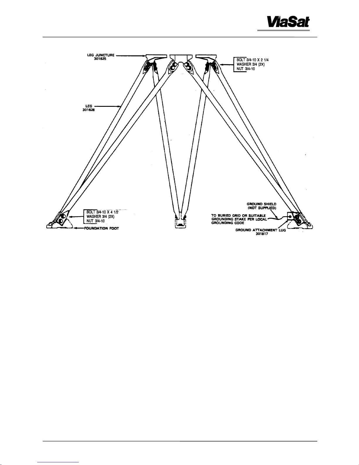
1. As shown in Figure 2-1, place one end of a leg onto a leg
juncture maintaining proper orientation of bend in leg.
Bolt in place with 3/4-10 x 2 1/4-inch bolt, washer, and
nut in two places. Repeat this operation with each of the
six legs and three leg junctures.
42S199F 2-8
Chapter 2 - Installation
Figure 2-1. Installation of Leg Assemblies
2. Attach two leg assemblies to each foundation foot and bolt the two leg ends to
the foundation foot using 3/4-10 x 4 1/2-inch bolt, washer, and nut in six places.
At one foundation foot, install a ground attachment lug to the leg ends before
bolting the leg ends to the foundation foot. Then ground antenna according to
local grounding codes.
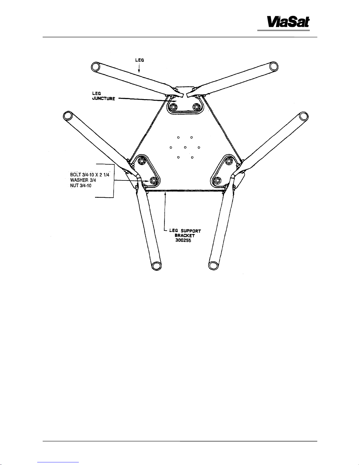
3. As shown in Figure 2-2, position the leg support bracket, flanges down, on top of
the previously assembled leg junctures. Bolt leg support bracket in place at the
two inboard holes of each leg juncture using 3/4-10 x 2 1/4-inch bolt, washer,
and nut in six places.
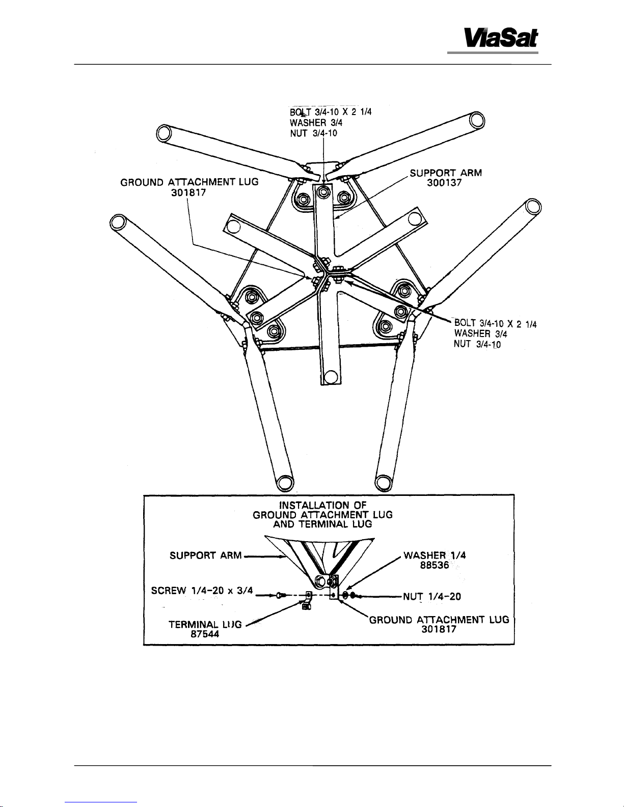
4. Attach short extension of each support arm to the center hole at the underside of
each leg juncture using 3/4-inch bolt, washer, and nut in three places. Refer to
Figure 2-3.
5. Before fastening the support arms together, install a ground attachment lug to
the support arm at one of the center locations. Then attach a terminal lug to the
ground attachment lug using 1/4-20 x 3/4-inch screw, washer, and nut. This
will be used later to ground the antenna feed/LNBs.
42S199F 2-9

Chapter 2 - Installation
6. Bolt the three support arms together at the center using 3/4-10 x 2 1/4-inch bolt,
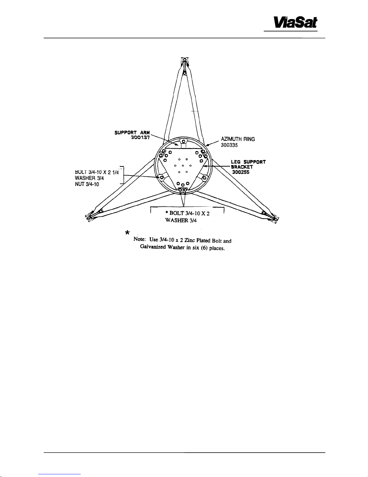
7. Position the azimuth ring on top of the leg support bracket and bolt in place at
8. As shown in Figure 2-4, bolt the long extension of each support arm to the
9. Using the following sequence, as shown in Figure 2-5, torque all 3/4-inch
washer, and nut in three places.
the outboard holes using 3/4-10 x 2-inch bolt and washer in six places. Refer to
Figure 2-4.
azimuth ring using 3/4-10 x 2-inch bolt, washer, and nut in three places.
fasteners to 250 ft-lbs (333 Nm).
a. Torque the two inboard bolts of each leg juncture.
b. Torque the six outboard bolts of each leg juncture which connect the azimuth
ring to the leg junctures.
NOTE
Using a carpenters level, make sure that the azimuth ring
remains level during steps c and d.
c. Torque the two bolts at each foot.
d. Torque two bolts at the upper end of each leg.
e. First, snug all bolts in the support arms to ensure that there is no binding of the
arms at any connecting point; then torque all nine bolts in the support arms.
42S199F 2-10
Chapter 2 - Installation
Figure 2-2. Installation of Leg Support Bracket
42S199F 2-11
Chapter 2 - Installation
Figure 2-3. Installation of Support Arms
42S199F 2-12
Chapter 2 - Installation
Chapter 2 - Installation
Figure 2-4. Installation of Azimuth Ring
42S199F 2-13
42S199F 2-13
 Loading...