

ViaSat Business Hotspots Installation Manual
Business Hotspots
Installation Guide
August, 2019

Viasat Business Hotspots Installation Guide
Page | 2
Contents
Wi-Fi network installation ................................................................................................................................................................ 3
Equipment ......................................................................................................................................................................................... 4
Network connections .................................................................................................................................................................... 5
Signal flow ........................................................................................................................................................................................ 6
Required for installation .............................................................................................................................................................. 6
Installation instructions ............................................................................................................................................................... 7
Step 1 | Select equipment location ..................................................................................................................................... 7
Step 2 | Install CAT5e cable .................................................................................................................................................. 7
Step 3 | Mount outdoor AP .................................................................................................................................................... 7
Step 4 | Mount indoor AP ..................................................................................................................................................... 10
Step 5 | Install inside network equipment ..................................................................................................................... 11
Step 6 | Auto-configure equipment ................................................................................................................................. 12
Step 7 | Tie down outdoor cables ..................................................................................................................................... 19
Step 8 | Basic network troubleshooting ....................................................................................................................... 20
Step 9 | Complete documentation ................................................................................................................................... 20
Step 10 | Review Quick Start Guide with customer ................................................................................................... 21
Ruckus outdoor AP installation ................................................................................................................................................... 23
Ruckus indoor AP installation ...................................................................................................................................................... 30
Low-profile “stub” mount installation
...................................................................................................................................... 37
Terminating Ethernet cable ........................................................................................................................................................... 41

Viasat Business Hotspots Installation Guide
Page | 3
Wi-Fi Network Installation
Viasat Business Hotspots Installation Guide
Equipment
responsible for providing the power strip.
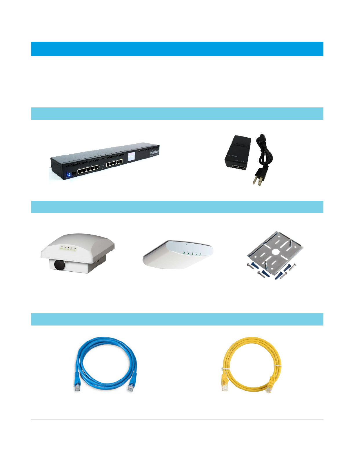
The Hotspots network equipment shown below will be installed at the customer site. Please note if the
customer already has Business Voice and is adding Business Hotspots, the Hotspots service will use the
same controller, and only the PoE injector/s, AP/s and Ethernet cables will be installed. The customer is
Controller PoE injector
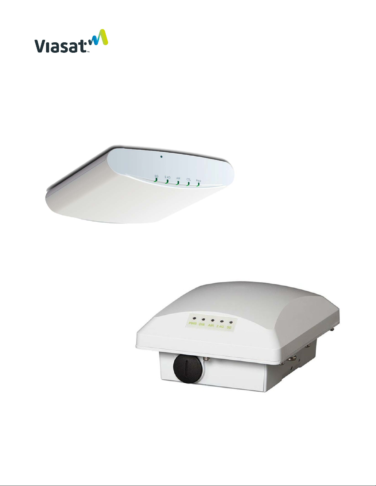
Outdoor AP Indoor AP Indoor AP mount kit
Indoor AP mount kit is labeled
for easy identification.
Blue Ethernet patch cable Yellow Ethernet patch cable
Page | 4
Viasat Business Hotspots Installation Guide
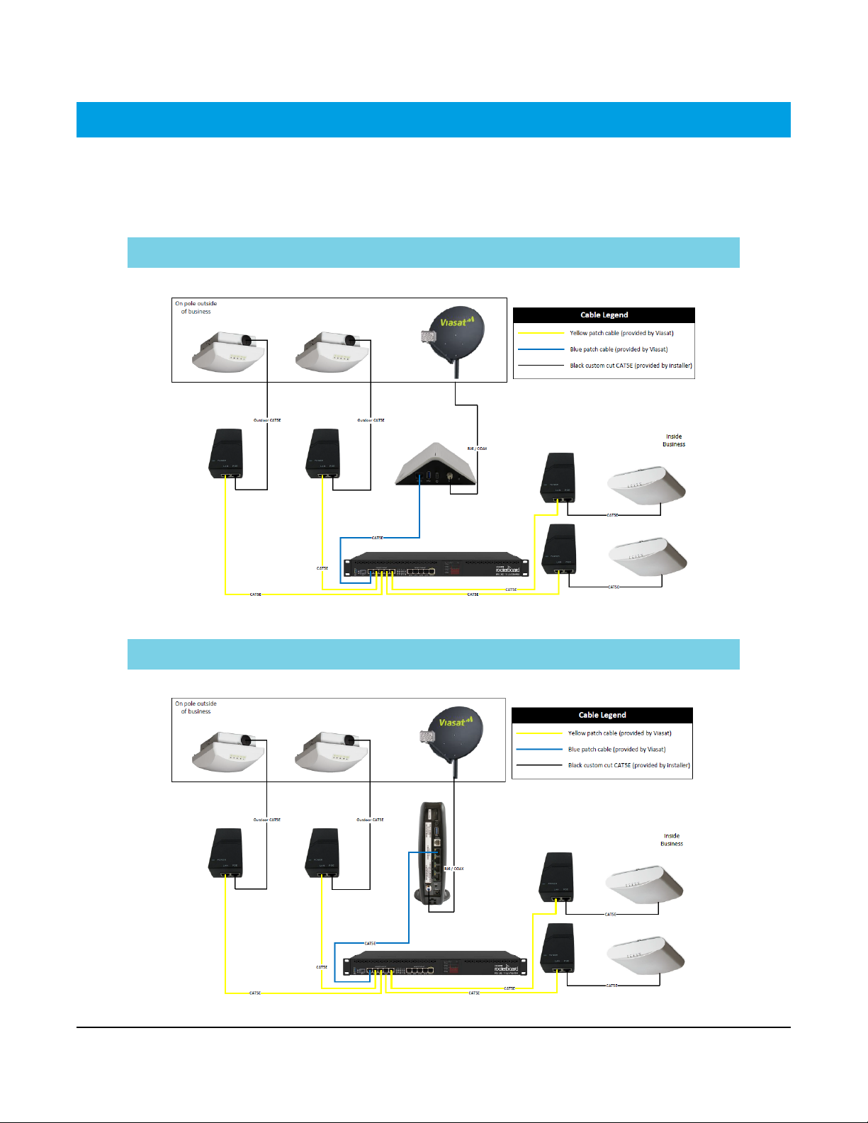
Network connections
When combined with Viasat Business Internet, the satellite modem used will be determined by the satellite
beam for the area. The VHG modem will be used for Viasat 2 beams, and the SB2+ modem is used for Viasat 1
beams. The diagrams below indicate how to connect the Hotspots network equipment using either modem.
VHG modem
Page | 5
SB2+ modem
Viasat Business Hotspots Installation Guide
Phillips head screwdriver
CAT5e outdoor-rated Ethernet cable
CAT5e/LAN cable continuity tester
#10 ground wire
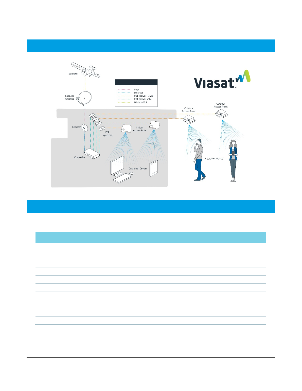
Signal flow
Required for installation
The following tools and supplies are required for installation:
Tools Supplies
Power drill CAT5e color-coded Ethernet patch cables (included)
Torque wrench CAT5e standard Ethernet cable
Flat head screwdriver RJ45 connectors and cable clips
13mm open-ended wrench Pass-through bushings
Cable strip tool Silicone sealant and Bishop tape
CAT5e crimping tool Outdoor UV-rated zip-ties
Cable snips Pole for outdoor AP (if needed) with lags/anchors/screws
Laptop or smartphone (required for Installer Portal) UL grounding supplies (wire, straps, screws, clamps, etc.)
Page | 6

Viasat Business Hotspots Installation Guide
Installation instructions
This installation guide provides comprehensive instructions for equipment installation and documentation
when adding the Business Hotspots network to the Viasat Satellite Internet solution.
Step 1 | Select equipment location
Outdoor AP & satellite antenna Indoor equipment
Select a secure location with clear line of site where the
most Wi-Fi users will be reached, preferably overlooking
a gathering area.
Install within 300 cable-feet of the controller at the
minimum height specified in Step 3 below.
Select a secure, climate-controlled location near a
power source and the modem for installing the
controller and PoE injector/s.
Install the indoor AP at ceiling level as close as possible
to the center of the intended coverage area where the
most Wi-Fi users will connect.
Step 2 | Install CAT5e cable
For each outdoor AP, cut to length (1) outdoor-rated CAT5e Ethernet cable no more than 300 cable-feet from
the location where the controller will be installed to the location where the AP will be mounted. Terminate
the ends and test each cable with a CAT5e cable tester. Install the cable, ensuring any holes that penetrate
the building are sealed.
For each indoor AP, cut to length (1) standard CAT5e Ethernet cable no more than 300 cable-feet from the
location where the controller will be installed to the location where the AP will be mounted. Terminate the
ends and test each cable with a CAT5e cable tester.
NOTE: Wait to tie down the cables until after all equipment is installed, configured and tested.
Step 3 | Mount the outdoor AP/s
Mount the outdoor AP/s in a secure location within 300 cable-feet of the controller. The outdoor AP must be
mounted with clear line of site to the Wi-Fi users in either of the following locations:
» A wall or outdoor patio-type ceiling at a minimum height of 10ft. (if ceiling is lower, mount at ceiling
height)
» A roof using a pole mount at a minimum of 2ft. and maximum of 10ft. above the roof, as long as there
is clear line of site to the users (follow the Viasat-approved Low-profile Pole Mount
instructions)
Refer to the Ruckus Outdoor AP installation instructions in this guide for additional information.
Avoid barriers and signal interference
The access point must be in a location that has clear line of site to the users, avoiding obstructions such as
buildings, trees, shrubs or any large structure that prevents clear line of site.
Page | 7
or Stub-mount
Viasat Business Hotspots Installation Guide
Below are examples of barriers that create interference:
Type of Barrier Interference
Wood, glass or synthetic material Low
Water, trees and bushes, bricks, and marble Medium
Plaster and concrete High
Metal Very high
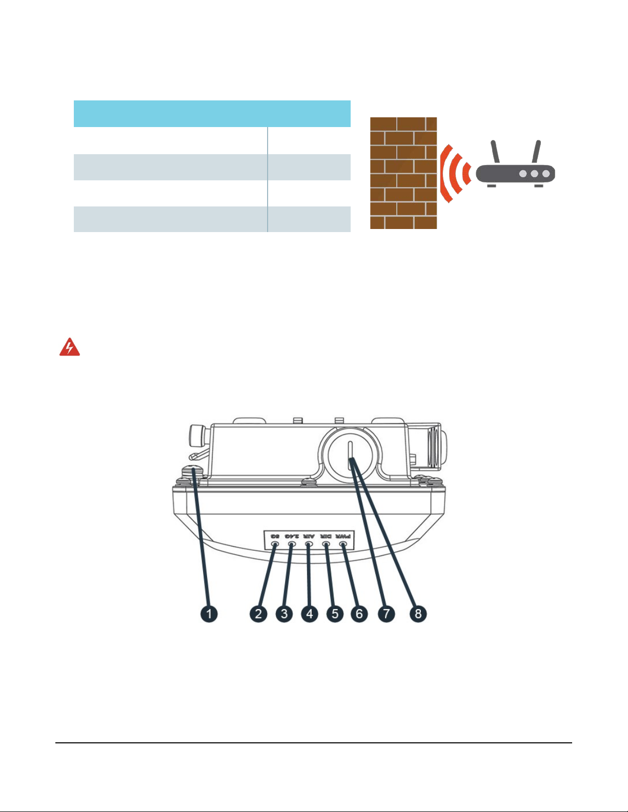
Ground the AP
Using the factory-supplied ground wire and ground screw, connect a good earth ground to the AP chassis
ground point. The earth ground screw is 9mm. Ensure that any replacement screw is no longer than 9mm to
prevent damage to the AP chassis.
WARNING! Do NOT run the ground wire to the ground block for the satellite antenna. Run it to a
separate ground source.
AP LEDs and other elements
Page | 8

Viasat Business Hotspots Installation Guide
# LED Color/State Meaning
Earth ground
1
screw
N/A Used to attach an earth ground to the AP.
2
3
4
5
5G
Green – Slow flashing
Green – Fast flashing
(twice per second)
2.4G
AIR N/A Not used.
DIR
Green - Flashing slow
Off WLAN service is down.
Amber - Solid
Green - Solid
(every 2 seconds)
WLAN is up, at least one downlink MAP is connected, and at least
Off WLAN service is down.
Amber - Solid WLAN is up. No clients are associated.
Green - Solid WLAN is up and at least one client is associated.
Off
(every 2 seconds)
Network problem. Cannot contact Ruckus management platform.
AP may still function if unable to contact the management platform.
WLAN is up, but no clients or downlink MAPs are
associated/connected.
The WLAN is up and at least one client is associated.
No downlink MAPs are connected.
WLAN is up and at least one downlink MAP is connected.
No clients are associated.
one client is associated.
Indicates AP is not being managed by the Ruckus management
platform. Contact Viasat installer support.
If problems are experienced, contact Viasat installer support.
6
7
8
PWR
POE IN RJ45
(Ethernet port)
RESET button
Page | 9
Green - Flashing fast
(2x/second)
Green - Solid Connected to the Ruckus management platform. Working properly.
Off No power to AP.
Red AP is starting up.
Green - Solid Routable IP address received.
Supports 10/100/1000Mbps connections, and receives Power over Ethernet (PoE).
DO NOT RESET THIS DEVICE UNLESS DIRECTED BY SUPPORT!
Receiving configuration or image upgrade.
Viasat Business Hotspots Installation Guide
Step 4 | Mount indoor AP/s
Each indoor AP provides up to 2,500 sq.ft. of coverage. Install the AP/s at ceiling level as close as possible to
the center of the intended coverage area where the most Wi-Fi users will connect. Determine which mount
type to use: drop-ceiling T-bar, flat surface, or mounting bracket. The AP must be mounted within 300 cablefeet of the controller. Refer to the Ruckus Indoor AP
installation instructions in this guide for additional
information.
Avoid barriers and signal interference
Mount the AP/s in an area free from obstructions or sources of interference, such as cement/brick, metal
(especially large metal objects), some appliances, analog phones, speakers, etc.
Below are examples of barriers that create interference:
Type of Barrier Interference
Wood, glass or synthetic material Low
Brick, marble, and objects containing water
Cement High
Metal, microwave ovens, A/C units,
cordless landline phones and headsets,
speakers, any device that consumes
large amounts of electricity
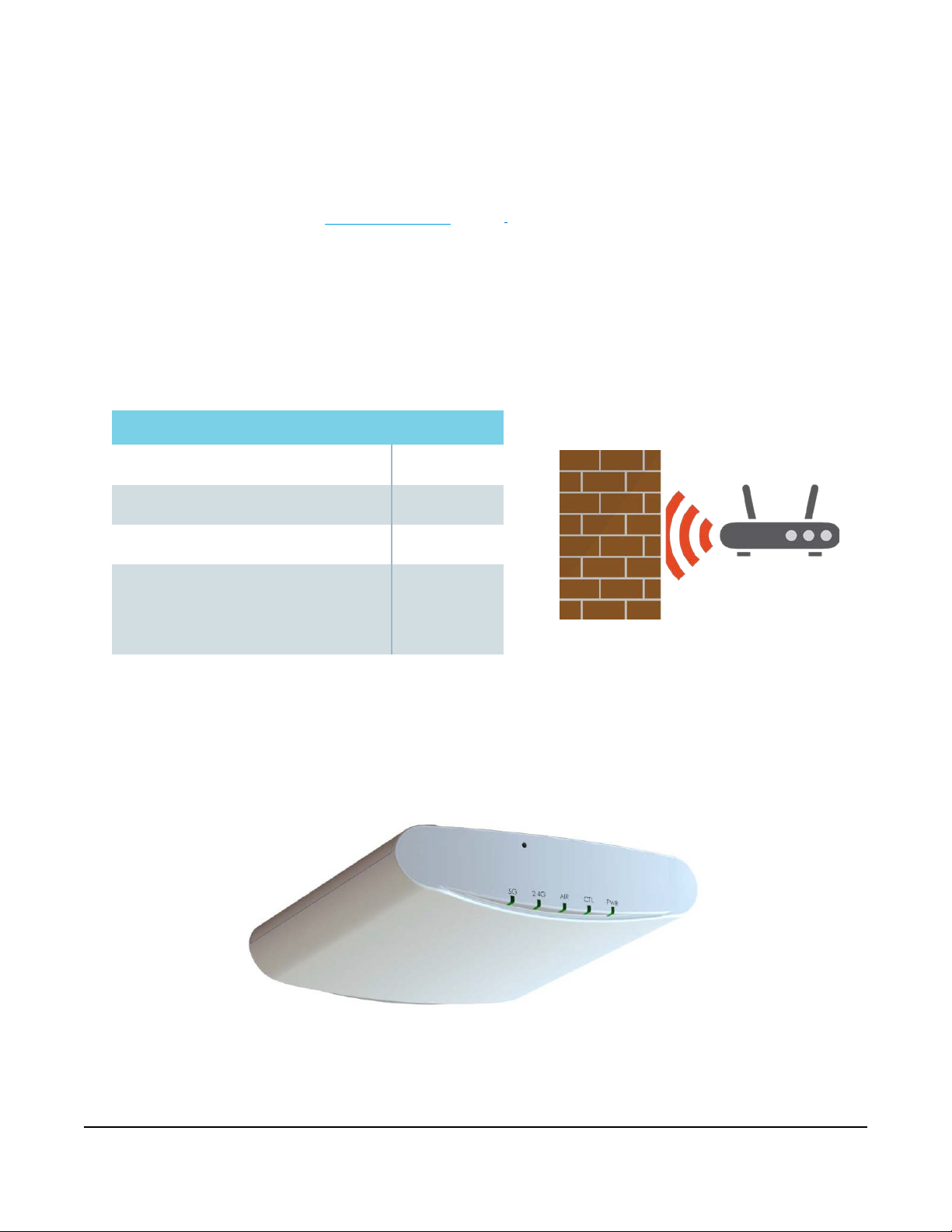
AP LEDs and other elements
Medium
Very high
Page | 10

Viasat Business Hotspots Installation Guide
LED Color/State Meaning
Contact Viasat installer support.
slow (every 2
AP may still function if unable to contact the management platform.
Green - Flashing fast
(2x/second)
Off Radio is down
5G
2.4G
AIR N/A Not used.
DIR
PWR
Amber - Solid Radio is up, no clients are connected to the 5 GHz radio
Green - Solid Radio is up, at least one client is connected to the 5 GHz radio
Off Radio is down.
Amber - Solid Radio is up, no clients are connected to the 2.4 GHz radio
Green - Solid Radio is up, at least one client is connected to the 2.4 GHz radio
Off
Green - Flashing
Green - Solid Connected to the Ruckus management platform. Working properly.
Off No power to AP.
Red AP is starting up.
Green - Flashing System started, no routable IP address detected.
Indicates AP is not being managed by the Ruckus management platform.
Network problem. Cannot contact Ruckus management platform.
Receiving configuration or image upgrade.
Green - Solid Routable IP address received.
Step 5 | Install inside network equipment
Install the controller and PoE injector/s in a secure, climate-controlled location near the satellite modem and
a power outlet. Do not place equipment on top of the controller.
NOTE: Ensure the equipment is easily accessible for future support. Avoid installing near a microwave,
as this will cause interference with the signal.
Page | 11
Viasat Business Hotspots Installation Guide
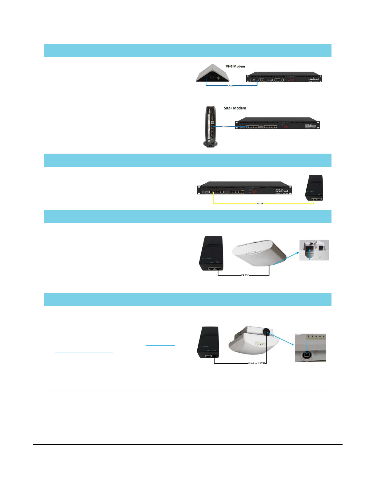
Modem to controller
into
NOTE: If the customer already has Business Voice,
skip this step. Proceed to Controller to PoE Injector.
1
Place the controller near the satellite modem.
2
Connect the blue Ethernet patch cable from the
modem to Port 1 on the controller.
NOTE: When using the SB2+ modem, the controller
must be plugged in to Port 1 (next to the white phone
port). The other ports will not work.
3
Plug in the power cable from the controller into the
power source.
Controller to PoE injector
1
Connect one end of a yellow Ethernet patch cable
one of Ports 2-5 on the controller.
2
Then connect the other end into the LAN port on the
PoE injector Repeat this step for each additional PoE
Injector.
PoE injector to indoor AP
1
Connect one end of the standard CAT5e Ethernet
cable into the POE port on the PoE injector.
2
Then connect the other end of the Ethernet cable into
the POE IN Ethernet port on the back of the AP.
3
Plug the PoE injector/s into the power source.
4
After boot-up, verify that the PWR LED on the AP is a
steady green.
5
Repeat this step for each additional AP.
OR
1
Connect one end of the outdoor-rated Ethernet
cable into the POE port on the PoE injector.
2
Then connect the other end to the cable through
the cable gland assembly to the Ethernet port on
the front of the AP. (See Step 1 of the
installation instructions on page 25.)
3
Plug the PoE injector/s into the power source.
4
After boot-up, verify that the PWR LED on the AP is a
steady green.
5
Repeat this step for each additional AP.
Step 6 | Auto-configure equipment
The controller and AP/s are set up to automatically configure and register with Viasat through the Installer
Portal. To initiate this process, the MAC Address of the controller must be entered into the Installer Portal,
which triggers discovery of the equipment.
Page | 12
PoE injector to outdoor AP
Outdoor AP
Viasat Business Hotspots Installation Guide
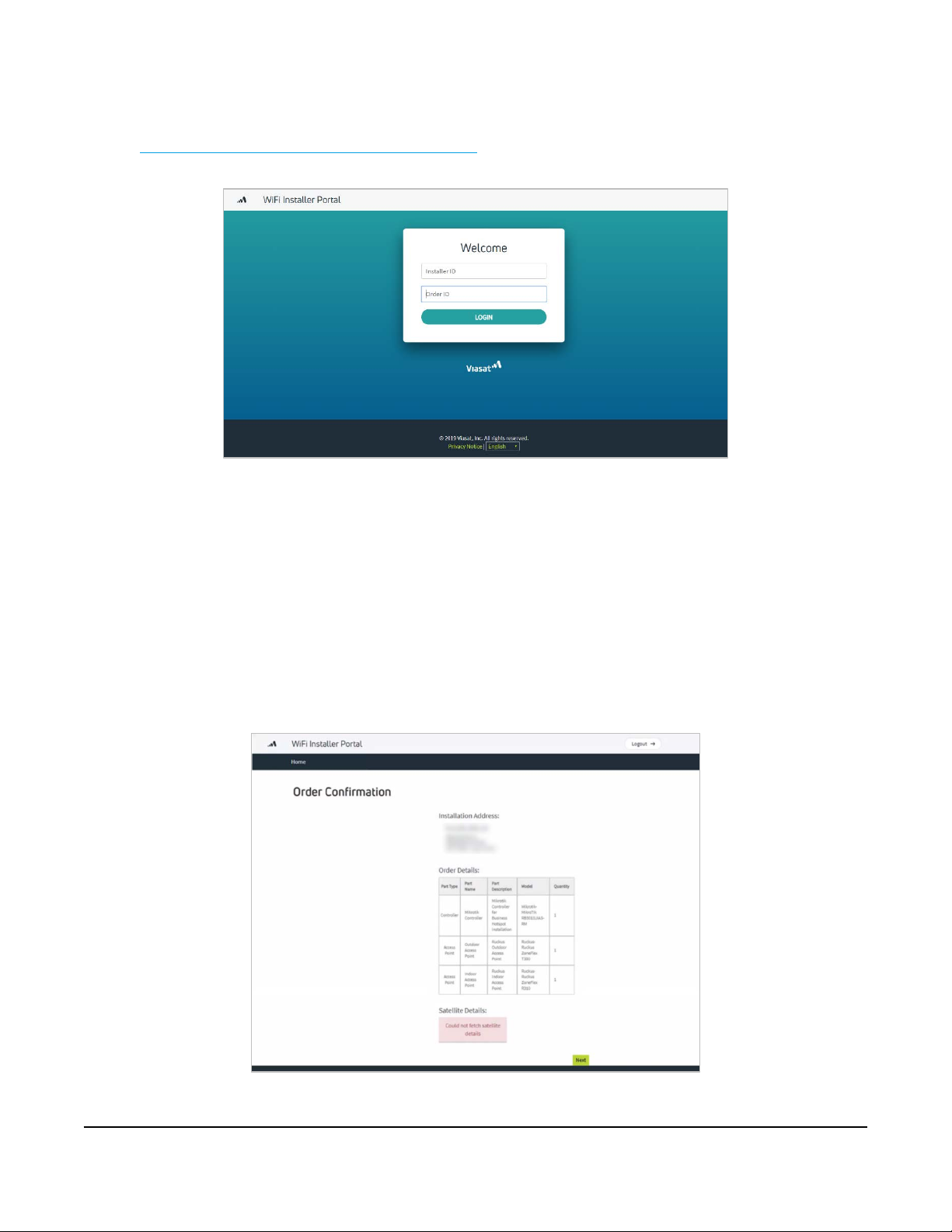
1
To access the Installer Portal, using a smartphone, go to
https://partners.wifi.viasat.com/install/bhlogin
found in the notes section in FSM.
and log in using your FSM Tech ID and the order ID
NOTE: If the customer location is in an area with limited cell phone coverage, use your laptop and
connect to Port 10 on the controller to start the configuration process. During the process, the
internet access will be interrupted. If the progression appears to have stalled, unplug the network
cable to the laptop and plug it back in. Then log out of the portal and log back in. If this does not
resolve the issue, contact Installer Relations at (888) 278-6869 and select Option 1 (Hotspots).
2
Once logged in, the order confirmation appears, showing the installation address and order details
(satellite details will not display on Hotspots orders currently).
Confirm the equipment listed in the order details matches what was shipped. If there is a discrepancy,
contact Installer Relations immediately. The equipment must match for the installation to occur (no
partial Wi-Fi installations). Click next to confirm the order details.
Page | 13
 Loading...