

Page 1

Series 8116/8118
16-/18-Meter Earth Station Antenna
Installation and Operation Guide
Manual Part No.42S183D
April 2004
Page 2

Notice
All Rights Reserved
The information contained in this document is proprietary to ViaSat, Inc.
This document may not be reproduced or distributed in any form without
the consent of ViaSat, Inc.
The information in this document is subject to change without notice.
ViaSat, Inc. assumes no responsibility for any errors that may appear in
this document and does not warranty any specific application.
Any product names mentioned herein are used for identification purposes
only, and may be trademarks and/or registered trademarks of their
respective companies.
In all correspondence with ViaSat, Inc. regarding this publication, please
refer to:
Publication Number: 42S183D
Copyright ® 2002 ViaSat, Inc.
All rights reserved. No part of this book may be reproduced in any form
or by any means without permission in writing from ViaSat, Inc.
Page 3

____________________________________________________________________________________________
TABLE OF CONTENTS
NOTE
For a further or more detailed breakdown of section
contents, refer to the title page of each section.
SECTION 1
1-1
1-1
1-3
1-4
SECTION 2
2-1
2-1
2-1
2-2
2-2
2-3
2-4
2-4
2-5
2-5
2-9
2-10
2-10
2-10
2-12
2-13
2-14
2-15
2-17
2-21
2-22
2-24
2-32
2-32
2-33
2-33
GENERAL INFORMATION
Introduction to Manual
Description
Wind Load Options
Specifications
LOWER MOUNT INSTALLATION PROCEDURES
General
What to do About Visible Loss or Damage
What to do About Concealed Damage
How to Inventory Equipment Received
How to Return Equipment
General Mechanical Safety Summary
Emergency Plan
General Electrical Safety Summary
Resuscitation
Recommended Tools and Equipment
Recommended Installation Sequency
Recommended Torque Values
Site Preparation
Assembly of Lower Mount
Azimuth Bearing Ring Assembly
Leg Installation
Bottom Skin Plate Installation
Mezzanine Installation (Optional)
Ships Ladder Assembly and Installation (Optional)
Middle and Top Skin Plate Installation
Torquing Lower Mount Fasteners
Door Assembly and Installation
Grouting Baseplate and Skin Plate to Foundation
Hot Weather Grouting
Cold Weather Grouting
Grouting Procedures
____________________________________________________________________________________________
42S183D
SERIES 8116/8118 16/18-METER EARTH STATION ANTENNA iii
Page 4

TABLE OF CONTENTS
____________________________________________________________________________________________
SECTION 3
UPPER MOUNT INSTALLATION PROCEDURES
3-1
3-1
3-1
3-14
3-19
3-22
3-22
3-23
3-29
3-29
3-29
3-30
General
Azimuth Drive Anchor Installation
Rotating Frame Installation
Azimuth Drive Installation
Elevation Drive Installation
Hub Assembly and Installation
Hub Assembly
Hub Installation
Installing Guardrails and Ladders
Ladders Installation
Guardrails Installation
Miscellaneous Platform Hardware
SECTION 4
INSTALLATION OF REFLECTOR, SPARS,
SUBREFLECTOR, AND FEED
4-1
4-1
4-1
General
Installation of Reflector
Installation of Panel Mounting Ring and Optional LNA
Enclosure
4-4
4-15
4-23
4-29
4-31
4-37
4-37
4-40
Installation of 18M Truss Assemblies
Installation of 16M Truss Assemblies
Installation of Panels
Final Alignment of Panels
Installation of Spars and Subreflector
Installation of Model 8118 Feed
Installation of Feed
Installation of Waveguide
SECTION 5
OPERATION
5-1
5-1
5-1
5-2
5-5
General
Satellite Pointing Procedure
Feed Polarization
Subreflector Adjustment
Azimuth Sector Change Procedure
____________________________________________________________________________________________
iv
SERIES 8116/8118 16/18-METER EARTH STATION ANTENNA 42S183D
Page 5

TABLE OF CONTENTS
____________________________________________________________________________________________
SECTION 6
6-1
6-1
6-1
6-1
6-2
6-5
6-5
SECTION 7
7-1
7-1
7-1
APPENDIX A
APPENDIX B
APPENDIX C
MAINTENANCE
General
Periodic Maintenance
Weekly Maintenance
Monthly Maintenance
Bi-Monthly Maintenance
Yearly Maintenance
Corrosion Protection
OPTIONS
General
Feed Options
Lightning Protection
INSTALLATION CHECKLIST WITH MANUAL PAGE
REFERENCES
MECHNCIAL ALIGNMENT SPECIFICATION AND REPORT
FOR 16/18-METER LIMITED MOTION ANTENNA
(479820A)
CONTOUR ALIGNMENT SPECIFICATION AND RECORD
FOR 16/18-METER ANTENNA (479821B)
____________________________________________________________________________________________
42S183D
SERIES 8116/8118 16/18-METER EARTH STATION ANTENNA v
Page 6

Page 7

SECTION 1
1-1 Introduction to Manual
1-1 Description
1-3 Wind Load Options
1-4 Specifications
GENERAL INFORMATION
42S183D Series 8116/8118 16-/18-Meter Earth Station Antenna
Page 8

Page 9

____________________________________________________________________________________________
SECTION 1 GENERAL INFORMATION
INTRODUCTION TO
MANUAL
DESCRIPTION
This manual contains information needed to properly install,
operate, and maintain the 16-/18-Meter (16/18M) Earth Station
Antenna. This section contains general information on the 16/18M
antenna. Sections 2 through 4 contain information pertaining to
16/18M antenna installation. Sections 5 and 6 contain information
pertaining to operation and maintenance. Section 7 describes the
different configurations available for the 16/18M antenna.
Appendix A contains a complete antenna installation checklist with
page references for the detailed procedures. Appendix B and
Appendix C contain mechanical and contour alignment
specifications and report information for the antenna, respectively.
All warnings and cautions should be reviewed before any
procedures are performed. Failure to do so may result in personal
injury or equipment damage.
Periodic maintenance and corrosion protection procedures are
contained in Section 5. For replacing components of the antenna,
refer to the installation and assembly drawings contained in
Sections 2, 3, and 4.
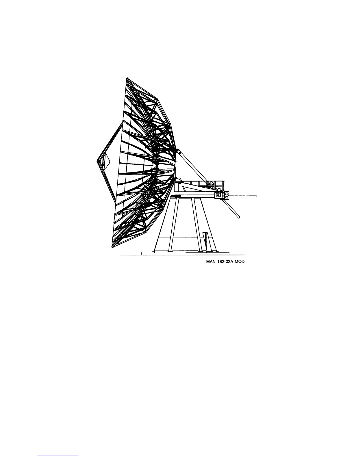
The 16/18M Earth Station Antenna provides a high-quality antenna
designed specifically for the INTELSAT-A station market. The
antenna is designed with many standard and optional features to
provide maximum user and application flexibility. Figure 1-1
shows an outline drawing of the 16M/18M antenna. The following
list identifies the main features of the antenna:
• Cassegrain feed for high-efficiency performance
____________________________________________________________________________________________
42S183D
SERIES 8116/8118 16-/18-METER EARTH STATION ANTENNA 1-1
• Designed for minimum maintenance
• Locked-in surface accuracy through precision tooling
• Frequency reuse feed
• Minimum site preparation required
• Full 360° azimuth travel in six over-lapping sectors
• Internal access for a clean, elegant look.
The 16/18M antenna is a Cassegrain design with a reflector and
subreflector that are shaped for maximum efficiency and low
sidelobes. The circularly polarized, four-port, frequency reuse feed
assembly includes a corrugated horn, orthomode transducer,
diplexers, and connecting waveguide. The transmit frequency
band is from 5.850 to 6.425 GHz and the receive frequency band is
from 3.625 to 4.200 GHz. All the performance specifications are
in full compliance with INTELSAT-A specifications.
Page 10
GENERAL INFORMATION
____________________________________________________________________________________________
Figure 1-1. 16-/18-Meter Motorized Antenna
____________________________________________________________________________________________
1-2
SERIES 8116/8118 16-/18-METER EARTH STATION ANTENNA 42S183D
Page 11

GENERAL INFORMATION
____________________________________________________________________________________________
The mount for both the 16- and 18-meter antennas is the same
elevation-over-azimuth pedestal. The elevation travel limits can be
set at any points between 0 and 90 degrees. The azimuth travel
range is a full 360 degrees covered in six overlapping sectors. Size
11 resolvers are supplied for position readout. Both axes are
equipped with 75 ton (667 kN) jack screws drives. As an option,
100 ton (890 kN) jack-screws can be provided to address additional
demands imposed by very high wind conditions on the 18M
antenna. Access to the drives and the reflector is gained from
inside the mount rather than from external ladders. The feed
electronics can be accessed at any elevation angle through the rear
of the hub.
The motorized package features variable-speed ac motors to
provide higher motor speeds for rapid stowing or slewing in
addition to the slow speeds required for satellite tracking. The
drives are equipped with variable-speed ac motors having a low
speed of about 0.010 degrees per second and a high speed slew rate
of about 0.1 degrees per second. The normal operational rate of
each axis is typically 0.01 to 0.015 degrees per second.
CAUTION
__________________________________________
No buildings, walls, fences, or other permanent
fixtures should be planned for installation any
closer than two meters from the antenna and
foundation envelope without consultation with
the factory.
Wind Load Options
__________________________________________
The 18-meter antenna will operate or drive to stow in winds up to
90 miles per hour (145 km/h) with the standard 75 ton (667 kN)
actuators. It will survive in any position in winds up to 105 miles
per hour (170 km/h). In the stow position (elevation axis at 90
degrees), the antenna will survive winds up to 140 miles per hour
(225 km/h). Under worst-case conditions, when the antenna is at 0
degrees elevation angle, it will take about 30 minutes to stow the
antenna using the variable speed motors. While the elevation axis
is being stowed, the azimuth axis can be turned to a more favorable
direction relative to the wind, if necessary. The azimuth axis never
needs to be stowed during adverse winds once the elevation axis is
at 90 degrees.
With the optional 100 ton (890 kN) actuators, the antenna will
operate or drive to stow in winds up to 90 miles per hour (145
km/h) but will survive in any position in winds up to 125 miles per
hour (200 km/h). In the stow position, the antenna will survive
winds up to 165 miles per hour (265 km/h).
____________________________________________________________________________________________
42S183D
SERIES 8116/8118 16-/18-METER EARTH STATION ANTENNA 1-3
Page 12

GENERAL INFORMATION
____________________________________________________________________________________________
The 16-meter antenna will operate or drive to stow in winds up to
110 miles per hour (175 km/h). It will survive in any position in
winds up to 125 miles per hour (200 km/h). In the stow position,
the antenna will survive winds up to 175 miles per hour (280
km/h).
SPECIFICATIONS
Function/Item Specification
General
Antenna Type Cassegrain, dual-reflector
Antenna Diameter 16 Meters
18 Meters
Reflector Construction
16-Meter Antenna 120 precision aluminum panels
18-Meter Antenna 168 precision aluminum panels
Mount Configuration Elevation-over-azimuth
Antenna Pointing Range
Azimuth 6 overlapping 90° sectors for a full 360°
Elevation 0 to 90° continuous
Antenna System Weight (Approximate)
16 Meter 124,000 lbs (56,233 kg)
18 Meter 127,000 lbs (57,594 kg)
Reflector Weight
16 Meter 39,000 lbs (17,686 kg)
18 Meter 42,000 lbs (19,047 kg)
Elevation Balance Angles
16 Meter 67°
18 Meter 69°
Drive Rates Variable over the range of:
Azimuth 0.0075 to 0.1125 degrees per second
(average)
Elevation 0.0044 to 0.0660 degrees per second
(average)
____________________________________________________________________________________________
1-4
SERIES 8116/8118 16-/18-METER EARTH STATION ANTENNA 42S183D
Page 13

GENERAL INFORMATION
____________________________________________________________________________________________
SPECIFICATIONS
Continued
Function/Item Specification
Electrical
Operating Frequency
Receive 3.625 to 4.200 GHz
Transmit 5.850 to 6.425 GHz
Feed Type Corrugated horn, frequency-reuse
Polarization Dual Circular
Gain at Midband (referenced to diplexer output ports)
Receive 55.2 + 20 log (f/4.0) dBi, 16-Meter
56.4 + 20 log (f/4.0) dBi, 18-Meter
Transmit 58.8 + 20 log (f/6.175) dBi, 16-Meter
60.1 + 20 log (f/6.175) dBi, 18-Meter
VSWR 1.25:1, Maximum
Axial Ratio
Receive 1.06:1
Transmit 1.06:1
Isolation Between Ports
Transmit 85 dB, Minimum
Receive 85 dB, Minimum
Beamwidth at Midband (nominal)
-3 dB Receive 0.32°, 16-meter
0.23°, 18-meter
-3 dB Transmit 0.21°, 16-meter
0.17°, 18-meter
First Sidelobe Level -14 dB, Maximum
Typical Antenna Noise Temperature
(Maximum @ 4 GHz referenced at output of OMT,
25°C (77°F), 50% RH, clear sky)
Elevation
5° 48
10° 41
20° 34
40° 32
60° 30
Power Handling Capability 5 kW continuous, 20 kW peak
(per port)
Feed Interface
Receive CPR-229G flange
Transmit CPR-137G flange
Voltage Requirements (actuators) 120/208V ac, 3-phase, 5-wire, 60 Hz or
220/380V ac, 3-phase, 5-wire, 50 Hz
(standard - others available)
Temperature (K)
____________________________________________________________________________________________
42S183D
SERIES 8116/8118 16-/18-METER EARTH STATION ANTENNA 1-5
Page 14

GENERAL INFORMATION
____________________________________________________________________________________________
SPECIFICATIONS
Continued
Function/Item Specification
Electrical - continued
Pointing Error 0.028° rms [with winds of 30 mi/h (48
km/h)gusting to 45 mi/h (72km/h) (1ß)]
0.040° rms [with winds of 45 mi/h
(72km/h)gusting to 60 mi/h (95 km/h)
(1ß)]
Tracking Error 0.02° rms with winds of 30 mi/h (48
km/h)gusting to 45 mi/h (72km/h)
Environmental
Feed Pressurization Leak Rate 500 cc/hr, Maximum
Feed Pressurization Relief Valve 0.5 psig
Ambient Temperature -40 to +60°C (-40 to +140°F)
Rainfall 100 mm/h (4 in/h)
Relative Humidity 0 to 100 % with condensation
Altitude Above Sea Level 0 to 10,000 feet (0 to 3048 m)
Sand and Dust As in desert regions
Salt Spray As in coastal regions
Fungi As in tropical regions
Solar Radiation 1.14 kW sq meter (360 Btu/h/sq ft)
Vertical Shock (survival) 0.1 G
Horizontal Shock (survival) 0.3 G
Earthquake Survival Per grade 11, Mercalli scale
Wind Survival (16M)
Operate Drives 110 mi/h (175 km/h)
Any Position 125 mi/h (200 km/h)
Stow Position 175 mi/h (280 km/h)
Wind Survival (18M)
Operate Drives 90 mi/h (145 km/h) (standard or optional
actuators)
Any Position 105 mi/h (170 km/h) (standard 75 ton
actuators)
125 mi/h (200 km/h) (optional 100 ton
actuators)
Stow Position 140 mi/h (225 km/h) (standard 75 ton
actuators)
165 mi/hr (265 km/h) (optional 100 ton
actuators)
________________________________________________________________
____________________________________________________________________________________________
1-6
SERIES 8116/8118 16-/18-METER EARTH STATION ANTENNA 42S183D
Page 15

SECTION 2
2-1 General
2-1 What to do about Visible Loss or Damage
2-1 What to do about Concealed Damage
2-2 How to Inventory Equipment Received
2-2 How to Return Equipment
2-3 General Mechanical Safety Summary
2-4 General Electrical Safety Summary
2-5 Recommended Tools and Equipment
2-9 Recommended Installation Sequency
2-10 Recommended Torque Values
2-10 Site Preparation
2-10 Assembly of Lower Mount
2-33 Grouting Baseplate and Skin Plate to Foundation
LOWER MOUNT INSTALLATION
PROCEDURES
42S183D Series 8116/8118 16-/18-Meter Earth Station Antenna
Page 16

Page 17

SECTION 2 LOWER MOUNT INSTALLATION PROCEDURES
GENERAL
WHAT TO DO ABOUT
VISIBLE LOSS OR
DAMAGE
WHAT TO DO ABOUT
CONCEALED
DAMAGE
This section contains general procedures for unpacking all of the
antenna hardware. This section also contains procedures for
installing the lower mount of the 16-/18-Meter Earth Station
Antenna. The installation of the upper mount (including rotating
frame, azimuth/elevation drives, hub, and optional work platform)
is contained in Section 3. The installation of the reflector, spars,
subreflector, and feed is contained in Section 4. General safety
precautions and procedures for the entire installation are also
described at the beginning of this section.
ViaSat thoroughly inspects and carefully packs all equipment
before shipment. At the time of shipment, the carrier assumes
responsibility for its safe delivery; therefore, do not return damaged
units to ViaSat. Instead, file a claim with the carrier as noted in the
paragraphs following the initial unpacking procedure given below:
1. Inspect shipping carton for visible damage.
2. Open the shipping carton.
3. Remove all packing material.
4. Inspect unit for visible damage.
5. Using packing list, check for missing items (see "How To Inventory
Equipment Received" below).
Make a note of any loss or evidence of external damage on the
freight bill or receipt, and have it signed by the carrier's agent.
Failure to adequately describe such external evidence of loss or
damage may result in the carrier refusing to honor a damage claim.
The form required to file such a claim will be supplied by the
carrier.
Concealed damage means damage which does not become
apparent until the unit has been unpacked. The contents may be
damaged in transit due to rough handling, even though the carton
may not show external damage. If you discover damage after
unpacking the unit, make a written request for inspection by the
carrier's agent within 15 days of the delivery date, then file a claim
with the carrier since such damage is the carrier's responsibility. If
you follow these instructions carefully, ViaSat guarantees its full
support of your claims to protect you against loss from concealed
damage.
____________________________________________________________________________________________
42S183D
SERIES 8116/8118 16-/18-METER EARTH STATION ANTENNA 2-1
Page 18

LOWER MOUNT INSTALLATION PROCEDURES
HOW TO INVENTORY
EQUIPMENT
RECEIVED
HOW TO RETURN
EQUIPMENT
Check off each item received against that list on the packing slip
included with the shipment, and verify that this list matches the
purchase order. If any items are missing, please notify ViaSat
immediately and return a copy of the packing slip with the missing
item(s) circled.
For a current list of telephone and email contract information
please refer to the Contact Information section of the ViaSat
internet site (http://www.viasat.com
). Select Products, Satellite
Ground Systems and Contact Us.
ViaSat’s Satellite Ground Systems division makes every
reasonable effort to ensure that all items arrive safely and in
working order. When equipment is received, which is not in
working order, return the equipment to the factory for repair or
replacement. Return the equipment according to the following
procedure. This procedure will apply whenever equipment is
returned for warranty or other services.
a) Notify ViaSat of the problem and request a Return Material
b) Tag or identify the defective equipment and note defect and
c) Reship equipment in original shipping container or use a strong
d) Package equipment using shock-absorbing material around all sides
e) Seal container securely and mark outside of container FRAGILE.
Authorization (RMA) number and shipping instructions.
circumstances, if any. If known, reference sales order, purchase
order and date equipment was received.
shipping container to protect equipment during shipment.
of equipment.
NOTE
Absence of the RMA number will cause a delay in processing
your equipment for repair. Be sure to include the RMA
number in all correspondence.
NOTE
ViaSat Inc will not accept freight collect. Be sure to ship all
items freight prepaid.
____________________________________________________________________________________________
2-2
SERIES 8116/8118 16-/18-METER EARTH STATION ANTENNA 42S183D
Page 19

GENERAL
MECHANICAL
SAFETY SUMMARY
LOWER MOUNT INSTALLATION PROCEDURES
WARNING
__________________________________________
Electrical shock from voltages used in this
system can cause injury or death. Prior to
making any electrical connections or performing
maintenance and repair, ensure power is
removed. Electrical connections should be made
only by qualified personnel in accordance with
local regulation.
__________________________________________
These are general mechanical safety precautions that are not related
to any specific procedure. They are recommended precautions that
personnel must understand and apply.
WARNING
__________________________________________
Installation or maintenance of antennas may
require persons to work at elevated work
stations. Whenever persons are working at eight
or more feet above ground and not on a guarded
platform, they should wear safety belts with at
least one, and preferably two, lanyards, with the
exception that trained and qualified persons may
work up to 25 feet (7.6m) if on an approved
ladder. In the sentence above, approved usually
means that the ladder is tied off once the person
has climbed but before work begins.
__________________________________________
____________________________________________________________________________________________
42S183D
SERIES 8116/8118 16-/18-METER EARTH STATION ANTENNA 2-3
Page 20

LOWER MOUNT INSTALLATION PROCEDURES
WARNING
__________________________________________
Overhead hazards, either because items may fall
or because a person may strike them
unintentionally, are typical around construction
sites or during installation of large antennas. It
is prudent to adopt the following rules:
1. Never stand underneath anything while it is
being hoisted.
2. Always wear a hard hat, especially if
someone is above you.
__________________________________________
WARNING
__________________________________________
Ensure that all electrical tools and equipment
are properly grounded.
__________________________________________
Emergency Plan
Have an emergency plan. Know the procedures for obtaining firstaid and fire-fighting assistance. Plan your work and maintain good
housekeeping; the safety and quality of the product are at stake.
GENERAL
ELECTRICAL SAFETY
SUMMARY
These are general electrical safety precautions that are not related
to any specific procedure. These are recommended precautions
that personnel must understand and apply.
____________________________________________________________________________________________
2-4
SERIES 8116/8118 16-/18-METER EARTH STATION ANTENNA 42S183D
Page 21

Resuscitation
RECOMMENDED
TOOLS AND
EQUIPMENT
LOWER MOUNT INSTALLATION PROCEDURES
WARNING
__________________________________________
Avoid shorting circuits when using metal tools.
Some circuits have high current capability
which, when shorted, will flash and may cause
burns and/or eye injury.
Remove all jewelry and exposed metal objects
from body and clothing before performing
maintenance, adjustments, and/or
troubleshooting. Before working inside the
equipment, remove all power, unless power is
required to perform procedures. Do not replace
parts with power on.
Replacement of fuses or other parts must be
done using identical types and ratings.
Substitution of non-identical parts may cause
safety and fire hazards.
Servicing this equipment may require working
with protective covers removed and ac power
connected. Extreme caution must be exercised
during these procedures.
Death or severe injury may result if personnel
fail to observe safety precautions.
__________________________________________
Personnel working with or near hazardous chemicals or voltages
should be familiar with modern methods of resuscitation.
Tables 2-1 through 2-4 list the tools and equipment needed for
installing ViaSat’s 16 or 18 meter antenna. Table 2-1 is a list of
hand tools. Table 2-2 is a list of on-site requirements such as
cranes, steel chokers, and an air compressor. Table 2-3 is a list of
precision items required such as a theodolite and level. Table 2-4
is a list of installation aids, rigging, and expendable items such as
air wrenches, slings, ladders, and safety items, some of which may
be available at the site.
____________________________________________________________________________________________
42S183D
SERIES 8116/8118 16-/18-METER EARTH STATION ANTENNA 2-5
Page 22

LOWER MOUNT INSTALLATION PROCEDURES
Table 2-1. Hand Tools Required for Installation
Quantity Description
1 Set* Combination wrenches up to 1 inch size
1 Each* 3/4 inch combination wrench
1 Each* 7/8 inch combination wrench
1 Each* 1 1/16 inch combination wrench
1 Each 1 1/8 inch combination wrench
1 Each* 1 1/4 inch combination wrench
1 Each* 1 5/8 inch combination wrench
1 Each* 1 7/8 inch combination wrench
1 Each* 2 inch combination wrench
1 Each 18 inch adjustable (Crescent) wrench
1 Each 24 inch adjustable (Crescent) wrench
1 Each 24 inch pipe wrench
1 Each* 1 1/16 inch spud wrench
1 Each* 1 1/4 inch spud wrench
1 Each* 1 5/8 inch spud wrench
1 Set 3/8 inch drive ratchet, extensions, and sockets from 3/8 to 7/8
1 Set* 1/2 inch drive ratchet, extensions, and sockets from 7/16 to 1
1 Each* 3/4 inch x 1/2 inch drive socket
1 Each* 7/8 inch x 1/2 inch drive socket
1 Each* 1 1/16 inch x 1/2 inch drive socket
1 Each* 1 1/4 inch x 1/2 inch drive socket
1 Each Socket adapter, 1/2 inch female to 3/4 inch male
1 Set* 3/4 inch drive ratchet, extensions, and sockets from 7/8 to 2
1 Each* 1 1/4 inch x 3/4 inch drive socket
1 Each* 1 5/8 inch x 3/4 inch drive socket
1 Each* 1 7/8 inch x 3/4 inch drive socket
1 Each* 2 inch x 3/4 inch drive socket
1 Each Socket adapter, 3/4 inch female to 1/2 inch male
1 Each 3/4 inch drive torque wrench, 250-300 ft-lbs capacity
1 Each 3/4 inch drive torque wrench, 600 ~-lbs capacity
2 Sets Screwdrivers, flat blade and Phillips
1 Set Hex keys (Allen wrenches) up to 1/2 inch size
1 Set* Nut drivers
2 Pairs Mechanic's pliers
1 Each Wire crimping tool
2 Pairs Lineman's pliers
2 Pairs Needle-nose pliers
1 Pair 12 inch channel lock pliers
2 Pair 10 inch vise grips
1 Each 4 pound sledge hammer
1 Each 8 pound sledge hammer
1 Each 24 ounce ball peen hammer
1 Each* Rawhide hammer
2 Each Claw hammer
2 Each 1 inch bull pin
2 Each 2 inch bull pin
1 Each Small slaver bar
inch size
1/4 inch size
inch size
____________________________________________________________________________________________
2-6
SERIES 8116/8118 16-/18-METER EARTH STATION ANTENNA 42S183D
Page 23

LOWER MOUNT INSTALLATION PROCEDURES
Table 2-1. Hand Tools Required for Installation - continued
Quantity Description
2 Each Large slaver bar
2 Each Crow (wrecking) bar
1 Each Pry bar
1 Each Band cutter
1 Each Hacksaw
6 Each Hacksaw blade
1 Each Automatic center punch
1 Each Drill index, 1/16 through 1/2 inch
6 Each 3/16 inch drill bits (for panel targets)
1 Each Tap and die set up through 3/8-16 size
1 Each 12 inch machinist's flat file
1 Each 12 inch round file
3 Each 6 inch C-clamp
1 Each Wire brush, stainless steel
1 Each Grease gun with cartridges
2 Rolls Electrical tape
1 Each Angle finder or magnetic base inclinometer
1 Each 24 inch carpenter's level
1 Each 12 inch machinist's scale with square head, 1/100 graduation
1 Each Feeler gage set
1 Each 12 foot tape
1 Each 25 foot tape
1 Each Chalk line reel (full of chalk)
1 Each 1 inch putty knife
1 Each 3 inch putty knife
1 Each 4 x 12 inch finishing trowel
1 Each 6 inch pointing trowel
4 Each 3/4 - 10 shoulder eye bolts (4-6 inch)
* Doubling the quantity of this item will enable a larger crew to install the
antenna more quickly.
______________________________________________________
____________________________________________________________________________________________
42S183D
SERIES 8116/8118 16-/18-METER EARTH STATION ANTENNA 2-7
Page 24

LOWER MOUNT INSTALLATION PROCEDURES
Table 2-2. On-Site Machinery and Equipment Required for
Quantity Description
1 Each* 45 ton crane with a 100 foot boom
4 Each 15 foot steel choker, 3/4 inch wire diameter
2 Each 20 foot steel choker, 1 inch wire diameter
4 Each Small, medium, and large shackles
1 Each Electric generator [or power hook-up point]
1 Each Air compressor with hoses and fittings, 600 cfm capacity
1 Each 20 foot scaffold [Not needed if mezzanine option is included
1 Each 50 foot high platform lift or bucket truck [Optional, but very
1 Each 5 gallon bucket (for grouting)
* Adding another crane will enable a larger crew to install the antenna more
quickly. [About 20 ton capacity with as much boom as possible to be used for
assembling trusses and intercostals.]
______________________________________________________
Table 2-3. Precision Tools Required for Installation
Quantity Description
1 Each
Machinist's level, 0.005 inch/foot graduation
1 Each
Wild Heerburg T2 theodolite with tribrach
1 Each
GV01 short focus lens for T2 theodolite
1 Each
GV02 short focus lens for T2 theodolite
1 Each
GV03 short focus lens for T2 theodolite
1 Each
Battery pack and light kit for T2 theodolite
1 Each
90 degree eyepiece set for T2 theodolite
1 Each 16/18 meter reflector alignment kit [Part number 479609]
______________________________________________________
Table 2-4. Installation Aids, Rigging, and Expendable Items
Quantity Description
1 Each 6 foot step ladder
1 Each 12 foot step ladder
2 Each 50 foot extension cord
2 Each Trouble light with 25 foot cord
1 Each* Transformer with duplex receptacle, 220 Volt to 110 Volt
1 Each Q-beam spotlight, 200,000 candle-power, 120 volt
1 Each 12 volt power supply for Q-beam spotlight
2 Each Flashlight, 2 D cell battery type
6 Each Flashlight battery, D cell
1 Each* 1/2 inch drive electric impact wrench
Installation
with mount]
useful]
Required
____________________________________________________________________________________________
2-8
SERIES 8116/8118 16-/18-METER EARTH STATION ANTENNA 42S183D
Page 25

RECOMMENDED
INSTALLATION
SEQUENCY
LOWER MOUNT INSTALLATION PROCEDURES
Table 2-4. Installation Aids, Rigging, and Expendable Items
Required - continued
Quantity
1 Each * 3/4 inch drive electric impact wrench
1 Each* 1/2 inch drive air impact wrench (if a compressor is available)
1 Each* 3/4 inch drive air impact wrench (if a compressor is available)
1 Each Cordless 3/8 inch drive drill motor with charger
1 Each 7 1/4 inch circular saw
3 Each Plywood blade for circular saw
4 Each 20 foot nylon sling
4 Each 15 foot nylon sling
4 Each 10 foot nylon sling
1 Each 50 foot nylon rope (1/2 inch)
4 Each Moving quilts
4 Each Safety belt with 2 D-rings
4 Each Safety lanyard
3 Each Tool belt
3 Each Bolt bag with tool holder
4 Each Hard hat
2 Pair Safety glasses
6 Pair Ear plugs
12 Pair Cloth gloves
6 Pair Leather palm gloves
1 Each First aid kit
1 Box Garbage bags
1 Can Hand Cleaner
6 Rolls Toilet paper
1 Each Ice Chest
1 Each Water Cooler
1 Each Umbrella
* Doubling the quantity of this item will enable a larger crew to install the antenna more
quickly.
Description
______________________________________________________
In order to ensure proper and trouble-free installation, the following
installation sequence is recommended:
1. Site Preparation (contained in manual #42S182)
2. Assembly of Lower Mount (contained in this section)
3. Assembly of Upper Mount (contained in Section 3)
4. Installation of Reflector (contained in Section 4)
5. Assembly of Spars and Subreflector (contained in Section 4)
6. Installation of Feed, Spars, and Subreflector (contained in Section 4)
7. Electrical Installation (contained in manual #42S197)
Appendix A provides a checklist with manual page number
references. The checklist follows the recommended sequence listed
above.
____________________________________________________________________________________________
42S183D
SERIES 8116/8118 16-/18-METER EARTH STATION ANTENNA 2-9
Page 26

LOWER MOUNT INSTALLATION PROCEDURES
RECOMMENDED
TORQUE VALUES
The following list contains the recommended torque values for all
antenna fasteners.
__________________________________________
Do not torque any fasteners until specifically
directed to torque a fastener. As fasteners are
installed, tighten finger tight only.
__________________________________________
1 1/4-inch Fasteners 1100 ft-lbs (1491 Nm)
1-inch Fasteners 600 ft-lbs (813 Nm)
3/4-inch Fasteners 260 ft-lbs (353 Nm)
5/8-inch Fasteners 150 ft-lbs (203 Nm)
1/2-inch Fasteners 76 ft-lbs (103 Nm)
3/8-inch Fasteners 31 ft-lbs (42 Nm)
5/16-inch Fasteners 24 ft-lbs (33 Nm)
1/4-inch Fasteners 9 ft-lbs (12 Nm)
SITE PREPARATION
Refer to 16-/18-Meter Earth Station Antenna Site Preparation
Technical Manual #42S182 for information needed to properly
locate and install the foundation for the 16-/18-Meter (16/18M)
Earth Station Antenna.
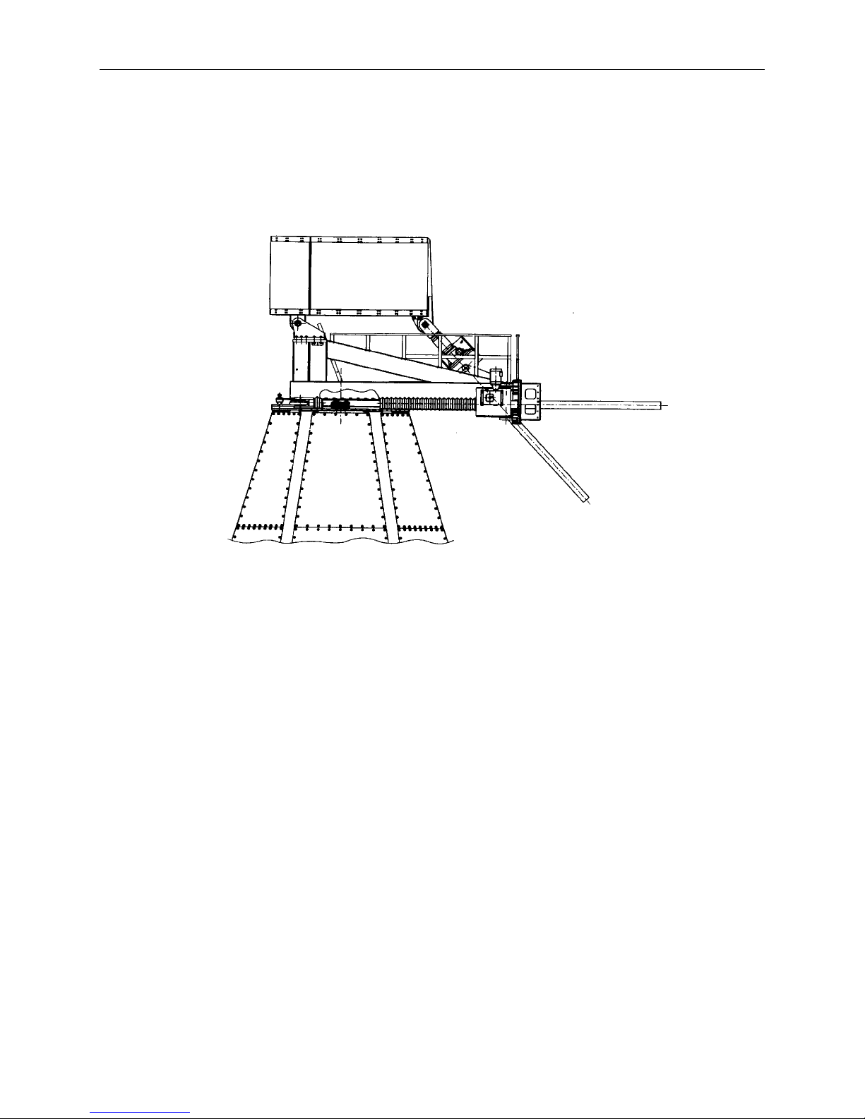
ASSEMBLY OF
LOWER MOUNT
The following procedure describes the complete assembly of the
lower mount for the 16- or 18-meter antenna. The completed
lower and upper mount assembly is identified in Figure 2-1. A
crane will be required during the entire assembly of the 16- or 18meter antenna. (The crane is required during the entire installation
process except for the site preparation and electrical installation.)
CAUTION
____________________________________________________________________________________________
2-10
SERIES 8116/8118 16-/18-METER EARTH STATION ANTENNA 42S183D
Page 27
LOWER MOUNT INSTALLATION PROCEDURES
Figure 2-1. Completed Mount Assembly With Hub
____________________________________________________________________________________________
42S183D
SERIES 8116/8118 16-/18-METER EARTH STATION ANTENNA 2-11
Page 28

LOWER MOUNT INSTALLATION PROCEDURES
Azimuth Bearing Ring
Assembly
The platform plate is assembled on the ground and then installed
on the top of the mount after the columns are erected during the
frame installation procedure. Assemble the azimuth bearing ring
assembly in accordance with the following procedure.
__________________________________________
The following assemblies weigh from 870 lbs
(395 kg) to 9300 lbs (4218 kg). Use extreme care
when hoisting these assemblies into position.
__________________________________________
__________________________________________
Mount damage can occur if the platform plates
are not properly aligned. Ensure proper
alignment is maintained as described in the
following procedure.
__________________________________________
1. Block up 2 piece tapped plate (item 3 in Figure 2-2) with ends 0.125
inches apart forming a hexagon (access underneath for installation of
top skin mounting angle is required).
2. Using hoist set 2 piece mounting plate (item 2 in Figure 2-2) in place
rotating ends 60° from ends of item 3.
3. Using hoist set 2 piece top plate (item 1 in Figure 2-2) in place rotating
ends 60° from ends of item 2 and item 3.
4. Secure all three layers together through bolt holes indicated in Figure 22 using screws and washers (items 100 and 101). Note that only 6 bolts
are used in one segment of the hexagon. This is where the azimuth drive
pivot frame is installed at a later time.
5. Torque bolts to 600 ft-lbs (813 Nm).
6. Attach six top skin mount angles (item 8 in Figure 2-3) to underside of
azimuth bearing ring assembly using screw, two flat washers, and nut
(items 102, 103 and 104 in Figure 2-3). Hand tighten nuts.
The azimuth bearing ring assembly is now ready to be set on
top of the columns in accordance with the next procedure.
WARNING
CAUTION
NOTE
____________________________________________________________________________________________
2-12
SERIES 8116/8118 16-/18-METER EARTH STATION ANTENNA 42S183D
Page 29

LOWER MOUNT INSTALLATION PROCEDURES
Leg Installation
The leg assembly must be properly aligned and installed for all
assemblies to properly fit together. Install the legs and associated
frame assemblies in accordance with the following procedure.
WARNING
__________________________________________
The following assemblies weigh from 135 lbs
(61 kg) to 15355 lbs (16965 kg). Use extreme
care when hoisting these assemblies into position.
__________________________________________
1. Install one hex nut (item 100, Figure 2-3) on each of the 24 leg anchor
bolts (six sets of four) and one hex nut (item 104) on each of 38 skin
bottom angle anchor bolts. Locate top of the nut 1-inch above the pad.
2. Place one flat washer (items 101 or 103, Figure 2-3) on each hex nut.
3. Using hoist, lift leg (item 1) into position over one set of column anchor
bolts (weight = 2790 lbs, 1265 kg).
4. Align column bottom plate holes with anchor bolts so the column leans
inward toward center of mount and secure with four flat washers and
nuts (item 100 and 101). Hand tighten nuts.
5. Using ladder remove hoist from leg.
6. Install remaining 5 legs as described in steps 3 through 5.
7. Attach hoist to azimuth bearing ring assembly (item 2).
8. Lift azimuth bearing ring assembly to rest on top of 6 legs.
9. Align azimuth bearing ring assembly corner holes with holes in top
mounting plate of legs. (It may be necessary to lower some of the legs
using nuts on leg base in order to properly align the holes.)
10. Secure azimuth bearing ring assembly to top plate of legs with screw,
two flat washers, and nut (item 102, 103, and 104). Hand tighten.
11. Remove hoist from azimuth bearing ring assembly.
12. Torque azimuth bearing ring assembly bolts to 1100 ft-lbs
(1491 Nm). Azimuth bearing ring assembly bearing mounting surface
(top of item 2 in Figure 2-2) should be leveled now by adjusting leg
anchor nuts up or down as required.
____________________________________________________________________________________________
42S183D
SERIES 8116/8118 16-/18-METER EARTH STATION ANTENNA 2-13
Page 30

LOWER MOUNT INSTALLATION PROCEDURES
Bottom Skin Plate
Installation
The bottom skin angles, door skin angles, lower skin tees, lower
door tees, lower skins, and lower door skins (items 3, 4, 5, 7, 11,
and 13 in Figure 2-3) are installed prior to installation of the
optional mezzanine and stairway.
1. Attach lower skin tee (item 5, Figure 2-3) to inside surface of lower
skin (item 11) with bolt, two flat washers, and nut (item 105, 103, and
104). Hand tighten. (Five of these assemblies are required.)
2. Lift lower skin into position on outside of two legs which do not have
the foundation bolt pattern for the access door between the legs.
3. Align plate side holes with holes in leg and secure to leg with bolt, two
flat washers, and nut (item 105, 103, and 104) in each skin plate side
hole. Hand tighten.
4. Install bottom skin angle (item 3) on skin bottom angle anchor bolts
using the following procedure.
a. Align holes in vertical leg of bottom skin angle with holes in
bottom skin.
b. Secure angle to skin with bolt, two flat washers, and nut (item
105, 103, and 104).
c. Secure angle to anchor bolts using washer and nut (item 103
and 104).
d. Hand tighten fasteners.
5. Remove hoist from bottom skin plate.
6. Install remaining four bottom skin plates as described in steps 1 through
5.
7. Attach lower door tee (item 7) to inside surface of lower door skin (item
13) with bolt, two flat washers, and nut (item 105, 103, and 104). Make
sure slanted side of skin is to the right.
8. Attach lower door tee in the same manner as step 7 except place angled
side of lower door skin on the left side.
9. Lift left lower door skin assembly into position on outside of left leg.
10. Align plate angled side holes with holes in leg and secure to leg with
bolt, two flat washers, and nut (item 105, 103, and 104) in each skin
plate side hole. Hand tighten.
11. Install door skin angle same as step 4 above.
12. Install right lower door skin assembly as described in steps 9, 10, and
11.
____________________________________________________________________________________________
2-14
SERIES 8116/8118 16-/18-METER EARTH STATION ANTENNA 42S183D
Page 31

LOWER MOUNT INSTALLATION PROCEDURES
Mezzanine
Installation (Optional)
The optional mezzanine is installed at this time to aid in attaching
the top skin plates and aligning the azimuth bearing ring assembly.
Install the mezzanine in accordance with the following procedure
and Figure 2-4.
NOTE
Leave all fasteners hand tight until directed to
torque fasteners.
CAUTION
__________________________________________
The mezzanine is designed for a live load
(personnel and tools) of 200 lbs per square foot
(976 kg per square meter) or a concentrated load
of 300 lbs (136 kg).
__________________________________________
1. Attach hoist to floor support beam A (item 1, Figure 2-4).
2. Lift support beam into position between legs directly opposite from
door opening.
3. Align two slotted holes with leg bracket holes and secure with two
bolts, four flat washers, two oversized flat washers, and two nuts (items
100, 102, 103, and 101) at each end of support beam. Hand tighten.
4. Remove hoist from mezzanine support beam.
5. Install floor support beam F (item 5) in next clockwise position,
(viewing from top of mount assembly) using steps 1 through 4.
6. Install floor support beam C (item 2).
7. Install floor support beam D (item 6).
8. Install floor support beam E (item 3).
9. Install floor support beam B (item 4).
10. Lift stairway header beam (item 8) into position between support beam
(item 1) and stairway opening beam (item 7) which will be installed
next.
11. Secure stairway header beam with two bolts, four flat washers, and two
nuts (item 104,102, and 101) at beam A. Hand tighten.
12. Attach hoist to stairway opening beam (item 7).
____________________________________________________________________________________________
42S183D
SERIES 8116/8118 16-/18-METER EARTH STATION ANTENNA 2-15
Page 32

LOWER MOUNT INSTALLATION PROCEDURES
13. Lift stairway opening beam into position between beams B and F.
14. Align four holes in end plates with holes in beams B and F and secure
with screw, two flat washers, and nut (item 104, 102, and 101). Hand
tighten. Install remaining two sets of bolts, flat washers, and nuts
between stationary header beam and stairway opening beam.
15. Attach hoist to right floor support beam (item 9).
16. Lift right floor support beam into position between stairway opening
beam and support beam C on right side of mount (viewing inward from
door opening).
17. Align two end plate holes with holes in stairway opening beam and
secure with two screws, four flat washers, and two nuts (item 104, 102,
and 101).
18. Align end clip plate (item 11) with four holes each in right floor support
beam and support beam C.
a. Secure end clip plate in place using screw, two flat washers
and nut (item 104, 102, and 101) eight places.
b. Torque four bolts securing end clip plate to right floor support
to 260 ft lbs (353 Nm).
c. Hand tighten the bolts securing the end clip plate to support
beam C.
19. Remove hoist from right floor support beam.
20. Install left floor support beam (item 10) to stairway opening beam and
support beam E on left side of mount (viewing inward from door
opening) using steps 15 through 18.
21. Attach hoist to center floor beam (item 12).
22. Lift center floor beam into position between stairway opening beam and
support beam D. Slide end plate holes on center support beam over
studs at each end. (The center support beam is a removable beam to
allow for equipment installation and removal.)
23. Remove hoist from center support beam.
____________________________________________________________________________________________
2-16
SERIES 8116/8118 16-/18-METER EARTH STATION ANTENNA 42S183D
Page 33

LOWER MOUNT INSTALLATION PROCEDURES
Ships Ladder
Assembly and
Installation (Optional)
The optional ships ladder is first assembled on ground, then hoisted
into position and installed in the mount. Perform the following
procedures to assemble and install the ships ladder (refer to Figure
2-5).
ASSEMBLY OF SHIPS LADDER
1. Position stringers side by side with left hand stringer (item 1, Figure 2-
5) on left side and right hand stringer (item 2) on the right side. Lay
stringers flat with flanges upward.
2. Turn left hand stringer on edge with flanges toward right hand stringer.
3. Position one tread (item 11) inside stringer flanges and align hole in
tread with hole in stringer at nearest end of stringer.
a. Secure tread to stringer with screw, two flat washers, and nut
(item 100, 101, and 102).
b. Align slot in tread with hole in left hand stringer.
c. Secure tread with screw, two flat washers, and nut (item 100,
101, and 102).
d. Align slot in tread with hole in right hand stringer.
e. Secure tread with screw, two flat washers, and nut (item 100,
101, and 102).
f. Hand tighten fasteners.
NOTE
Assure that rough surface of tread will be up when the top end
of stringer is raised to mezzanine floor.
4. Turn right hand stringer (item 2) on edge with flanges toward left hand
stringer.
5. Align hole in tread with hole in right hand stringer.
a. Secure tread to stringer with screw, two flat washers, and nut
(item 100, 101, and 102).
b. Align slot in tread with hole in left hand stringer.
c. Secure tread with screw, two flat washers, and nut (item 100,
101, and 102).
d. Hand tighten fasteners.
6. Repeat steps 3 and 5 for all fourteen tread locations.
____________________________________________________________________________________________
42S183D
SERIES 8116/8118 16-/18-METER EARTH STATION ANTENNA 2-17
Page 34

LOWER MOUNT INSTALLATION PROCEDURES
7. Install top mount (item 3) between right hand and left hand stringer at
end of stringers which will be raised to join with the mezzanine floor.
a. Secure with screw, two flat washers, and nut (item 103, 104,
and 105) at both ends of top mount.
b. Hand tighten fastener.
8. Attach bottom mount (item 4) to bottom end of both stringers using
bolt, two flat washers, and nut (item 103, 104, and 105) through slotted
hole in bottom mount. Hand tighten.
9. Position right hand stanchion (item 10) on outside of the right hand
stringer just above the top tread.
10. Align holes in right hand stanchion with right stringer. Secure two
places using screw, two flat washers, and nut (item 100, 101, and 102).
Hand tighten.
11. Repeat step 9 and 10 just above the tenth tread, and the first tread.
12. Position left hand stanchion (item 9) on outside of left hand stringer just
above the tenth tread.
13. Repeat step 10.
14. Repeat step 12 and 13 just above the fifth tread and the first tread.
15. Position left handrail (item 5) inside of and on top of the three left hand
stanchion.
16. Align holes in handrail with stanchion and secure three places with
screw, two flat washers, and nut (item 100, 101, and 102). Hand
tighten.
17. Position left hand kneerail (item 7) on inside of left hand stanchion and
secure three places with screw, two flat washers, and nut (item 100, 101
and 102). Hand tighten.
18. Repeat step 15 on right side using right handrail (item 6) inside the four
right hand stanchions.
19. Repeat step 16 four places.
20. Repeat step 17 on right side using right hand kneerail (item 8) secure
four places.
21. Torque all 3/8-inch fasteners in treads, stanchions, handrails, and
kneerails to 31 ft-lbs. (42 Nm).
____________________________________________________________________________________________
2-18
SERIES 8116/8118 16-/18-METER EARTH STATION ANTENNA 42S183D
Page 35

LOWER MOUNT INSTALLATION PROCEDURES
SHIPS LADDER INSTALLATION
1. Attach hoist to ships ladder (see Figure 2-5).
2. Lift ships ladder into position in the stair opening (across the mount
from door opening).
3. Align three top mount holes at top of ladder with stairway header beam
holes.
4. Secure three places with screw, two flat washers, and nut (item 103,
104, and 105). Hand tighten.
5. Mark position on concrete where two holes on stair bottom mount meet
concrete floor.
6. Remove three bolts, washers, and nuts that secure ships ladder to
stairway header beam and lift ships ladder away from marked concrete
area.
7. Drill two 3/4-inch by 4-inch deep holes into concrete at marked
locations.
8. Insert expansion bolt (item 106) into expansion bolt holes and remove
nut and washer. (Retain these for use in step 10.)
9. Place ships ladder back in position and repeat step 4.
10. Secure bottom mount angles to concrete using the two nuts and washers
removed in step 8.
11. Level tread plate and torque bolts in slotted hole of bottom mount angle
to 260 ft-lbs (353 Nm).
12. Torque bolts in top of ships ladder to 260 ft-lbs (353 Nm).
13. Remove hoist from ships ladder.
14. Attach hoist to mezzanine guard rail (item 21, Figure 2-4).
15. Lift guard rail into position on mezzanine stairway opening beam.
16. Align guard rail bottom plate holes with holes in stairway opening beam
four places on each guard rail bottom plate.
17. Secure guard rail bottom plate to stairway opening beam with screw,
two flat washers, and nut (item 104, 102, and 101) 16 places.
18. Remove hoist from mezzanine guard rail.
____________________________________________________________________________________________
42S183D
SERIES 8116/8118 16-/18-METER EARTH STATION ANTENNA 2-19
Page 36

LOWER MOUNT INSTALLATION PROCEDURES
The grating may be lifted into place by hand or with the crane.
The stair landing grating and corner gratings weigh 20 lbs (9
kg) each and the center gratings weigh 100 lbs (45 kg) each.
MEZZANINE GRATING
1. Attach hoist to stair landing grating (item 13, Figure 2-4).
2. Lift grating into position on mezzanine at head of stairs.
The grating hold-down will be installed after the top skins are
installed and all fasteners in mount have been torqued.
3. Remove hoist from grating.
4. Attach hoist to corner grating C (item 15).
5. Lift grating to position on mezzanine at right side (facing inward from
door).
6. Remove hoist from grating.
7. Attach hoist to corner grating D (item 19).
8. Lift grating into position on mezzanine at right side (facing inward from
door).
9. Remove hoist from grating.
10. Attach hoist to corner grating A (item 17).
11. Lift grating into position on mezzanine at left side (facing inward from
door).
12. Remove hoist from grating.
13. Attach hoist to corner grating B (item 18).
14. Lift grating into position on mezzanine at left side (facing inward from
door).
15. Remove hoist from grating.
16. Attach hoist to center grating A (item 14).
17. Lift grating into position on mezzanine at center (by stairway).
NOTE
NOTE
____________________________________________________________________________________________
2-20
SERIES 8116/8118 16-/18-METER EARTH STATION ANTENNA 42S183D
Page 37

Middle and Top Skin
Plate Installation
LOWER MOUNT INSTALLATION PROCEDURES
18. Remove hoist from grating.
19. Attach hoist to center grating C (item 20).
20. Lift grating into position on mezzanine at center (near doorway).
21. Remove hoist from grating.
22. Attach hoist to center grating B (item 16).
23. Lift grating into position on mezzanine at center (mezzanine center).
24. Remove hoist from grating.
After the optional mezzanine, stairway, and grating installation is
complete, install the middle and top skins as follows.
WARNING
__________________________________________
The following assemblies weigh approximately
1525 lbs (692 kg) each. Use extreme care when
hoisting these assemblies into position.
__________________________________________
1. Attach upper skin tee (item 6, Figure 2-3) to top surface of middle
mount skin (item 10) at seven places with bolt, two flat washers, and
nut (item 105, 103, and 104). Hand tighten.
2. Lift middle mount skin into position on outside of two legs which do
not have the door opening between them.
3. Align plate side holes with holes in leg (eight holes in each leg) and
secure with bolt, two flat washers, and nut (item 105, 103, and 104).
4. Secure middle mount skin to lower skin tee at nine places using bolt,
two flat washers, and nut (item 105, 103, and 104). Hand tighten.
5. Repeat steps 1 through 4 on four more middle mount skins.
6. Attach upper skin tee (item 6) to inside top surface of middle door
mount skin (item 12) at seven places with bolt, two flat washers, and
nut (item 105, 103, and 104). Hand tighten.
7. Lift middle door mount skin into position using hoist. Locate between
two legs where door will be located.
8. Repeat step 3.
____________________________________________________________________________________________
42S183D
SERIES 8116/8118 16-/18-METER EARTH STATION ANTENNA 2-21
Page 38

LOWER MOUNT INSTALLATION PROCEDURES
9. Secure the middle door mount skin to the lower door tee, two places
each side of door opening, using bolt, two flat washers, and nut (item
105, 103, and 104). Hand tighten.
10. Lift upper mount skin into position using hoist. Locate between two
legs.
11. Align plate side holes with holes in leg (thirteen holes in each leg) and
secure with bolt, two flat washers, and nut (item 105, 103, and 104).
Hand tighten.
12. Secure the upper mount skin to the upper skin tee at seven places with
bolt, two flat washers, and nut (item 105. 103 and 104). Hand tighten.
13. Secure the upper mount skin to the top skin mount angles, four places,
with bolt two flat washers, and nut (item 105, 103 and 104). Hand
tighten.
14. Repeat steps 10 through 13 for remaining five upper mount skin panels.
Torquing Lower
Mount Fasteners
The mount is torqued from the top down in order to secure
everything together prior to grouting the base. Perform the
following procedures to properly torque all mount fasteners.
1. Loosen all nuts securing bottom skin mount angles to foundation by a
couple turns (this will allow the skin to be pulled tight from the top
down).
Do not loosen nuts securing legs to foundation.
2. Tighten fasteners holding bearing ring assembly plate together to 600
ft-lbs (813 Nm).
3. Tighten fasteners securing bearing ring assembly to top mounting plate
of legs to 600 ft-lbs (813 Nm).
4. Tighten bearing ring assembly plate to top skin mount angle fasteners to
600 ft-lbs (813 Nm).
5. Tighten upper mount skin to leg fasteners to 600 ft-lbs (813 Nm).
Tighten from top down.
6. Tighten upper mount skin plate to upper skin tee fasteners to 600 ft-lbs
(813 Nm).
7. Tighten middle mount skin panels to upper mount skin tee fasteners to
600 ft-lbs (813 Nm).
NOTE
____________________________________________________________________________________________
2-22
SERIES 8116/8118 16-/18-METER EARTH STATION ANTENNA 42S183D
Page 39

LOWER MOUNT INSTALLATION PROCEDURES
8. Tighten middle mount skin panels to leg fasteners to 600 ft-lbs
(813 Nm). Tighten from top down.
9. Tighten middle mount skin panels to lower skin tee fasteners to 600 ftlbs (813 Nm).
10. Tighten lower mount skin panels to lower skin tee fasteners to 600 ftlbs (813 Nm).
11. Tighten lower mount skin panel to leg fasteners to 600 ft-lbs
(813 Nm). Tighten from top down.
12. Tighten lower mount skin panel to bottom skin angle fasteners to 600
ft-lbs (813 Nm).
13. Ensure bottom nuts on leg base are snug against plate.
14. Tighten top nuts on leg base to 1100 ft-lbs (1491 Nm).
15. Ensure bottom nuts on bottom skin angle are snug against angle.
16. Tighten top nuts on bottom skin angle to 150 ft-lbs (200 Nm).
17. Tighten mezzanine guard rail to stair opening beam fasteners to 260 ftlbs (353 Nm).
18. Tighten ships ladder to stair stringer support beam fasteners to 260
ft-lbs (353 Nm).
19. Tighten stair stringer to stair to right mount fasteners to 260 ft-lbs
(353 Nm).
20. Tighten bottom mount to floor fasteners to 150 ft-lbs (203 Nm).
21. Tighten bottom mount to stringer fasteners to 260 ft-lbs (353 Nm).
22. Tighten all mezzanine edge beam to leg fasteners to 260 ft-lbs
(353 Nm).
23. Install mezzanine grating hold downs (item 105 Figure 2-4) in
accordance with the following procedure.
a. Space hold down approximately two feet (61 cm) apart (in
each direction) with a minimum of two per grating.
b. Transfer holes to mezzanine beams using a tap for 1/4-20
screws.
c. Install each hold down with one socket head cap screw (item
106).
____________________________________________________________________________________________
42S183D
SERIES 8116/8118 16-/18-METER EARTH STATION ANTENNA 2-23
Page 40

LOWER MOUNT INSTALLATION PROCEDURES
Door Assembly and
Installation
After the mount is torqued the mount door and frame should be
assembled and then installed from the inside of the mount in accordance
with the following procedures.
1. From inside mount, place right door skin (item 14, Figure 2-3) with
small end pointing toward door opening and short flange on floor and
turned toward outside of door.
2. From inside mount, locate left door skin (item 15) on floor with small
end pointing toward door opening and short flange on floor and turned
opposite from the flange in step 1 above.
3. Locate top door skin (item 16) across the narrow end of left and right
door skins. The long flange should be placed on the floor and end
flanges overlapping on outside of door skins.
4. Secure top door skin to left and right door skins in two places each side
using screw, two flat washers, and nut (item 108, 109, and 110).
5. Install one door side channel (item 18) on right door skin.
6. Secure door side channel in six places using screw, two flat washers,
and nut (item 108, 109, and 110). Torque to 31 ft-lbs
(42 Nm).
7. Install one door side channel (item 18) on left door skin.
8. Repeat step 6.
9. Locate door top channel (item 17) on upper door skin.
10. Secure door top channel four places using screw, two flat washers, and
nut (item 108, 109, and 110). Torque to 31 ft-lbs (42 Nm).
11. With one person on each side of door assembly (item 111), lift
assembly and slide it onto the door side channels until door frame top
covers door top channel.
NOTE
Make sure that the door will open inward when erected in the
door opening.
12. Check that door frame rails are touching right and left door skins and
completely hitting door side channels.
13. Check that top door frame rail is touching top door skin and hitting
door top channel.
14. With door frame and side skin panels still laying on the ground, drill
two holes in top of door frame and door top channel and secure door
frame in place using self tapping screw (item 106).
15. With door frame and skin panel still laying on the floor, drill two pilot
holes equally spaced through top door frame and top door channel
using drill bit (item 107, Figure 2-3) and secure with self tapping
screws (item 106).
____________________________________________________________________________________________
2-24
SERIES 8116/8118 16-/18-METER EARTH STATION ANTENNA 42S183D
Page 41

LOWER MOUNT INSTALLATION PROCEDURES
16. Drill one pilot hole near bottom of each side door frame and install self
tapping screws (item 106).
NOTE
These two screws will be removed at a later procedure.
17. Set door assembly and side skins up in a vertical position.
18. Position bottom of right and left floor skins on doorway anchor bolts.
19. Secure with nut and flat washer (item 100 and 101, Figure 2-3), one on
each side. Hand tighten.
20. Align holes in right and left door skins with holes in lower and middle
door skin panels.
21. Secure in place, ten places on each side of door frame assembly, using
bolt, two flat washers, and nut (item 105, 103, and 104).
22. Secure top door skin, four places, using bolt, two flat washers, and nut
(item 105, 103, and 104).
23. Remove two self tapping screws installed at step 16.
24. Adjust door side skins to provide an equal gap between door and door
frame along sides and across the top.
25. Torque door side skin to lower door skin and middle door skin fasteners
to 260 ft-lbs (353 Nm).
26. Torque door top skin to middle door skin fasteners to 260 ft-lbs
(353 Nm).
27. Torque door side skin to doorway anchor bolts to 1100 ft-lbs
(1491 Nm).
28. Drill five pilot holes equally spaced through inside right door frame and
door side channel using drill bit (item 107).
29. Secure door frame to side channel using self tapping screw (item 106).
30. Repeat step 28 and 29 along inside left door frame.
31. From outside door, drill two pilot holes, equally spaced, through top
door frame and top door channel using drill bit (item 107).
32. Secure door frame to top door channel with self tapping screw (item
106).
33. From outside door, repeat step 28, 29, and 30.
____________________________________________________________________________________________
42S183D
SERIES 8116/8118 16-/18-METER EARTH STATION ANTENNA 2-25
Page 42

LOWER MOUNT INSTALLATION PROCEDURES
Figure 2-2. Azimuth Bearing Ring Assembly, 483183
____________________________________________________________________________________________
2-26
SERIES 8116/8118 16-/18-METER EARTH STATION ANTENNA 42S183D
Page 43

LOWER MOUNT INSTALLATION PROCEDURES
Figure 2-3. 16/18-Meter Mount Assembly (Sheet 1 of 3), 483184A
____________________________________________________________________________________________
42S183D
SERIES 8116/8118 16-/18-METER EARTH STATION ANTENNA 2-27
Page 44

LOWER MOUNT INSTALLATION PROCEDURES
Figure 2-3. 16/18-Meter Mount Assembly (Sheet 2 of 3), 483184A
____________________________________________________________________________________________
2-28
SERIES 8116/8118 16-/18-METER EARTH STATION ANTENNA 42S183D
Page 45

LOWER MOUNT INSTALLATION PROCEDURES
Figure 2-3. 16/18-Meter Mount Assembly (Sheet 3 of 3), 483184A
____________________________________________________________________________________________
42S183D
SERIES 8116/8118 16-/18-METER EARTH STATION ANTENNA 2-29
Page 46

LOWER MOUNT INSTALLATION PROCEDURES
Figure 2-4. 16/18-Meter Mezzanine Installation, 512020
____________________________________________________________________________________________
2-30
SERIES 8116/8118 16-/18-METER EARTH STATION ANTENNA 42S183D
Page 47

LOWER MOUNT INSTALLATION PROCEDURES
Figure 2-5. 16/18-Meter Stairway Installation, 483185
____________________________________________________________________________________________
42S183D
SERIES 8116/8118 16-/18-METER EARTH STATION ANTENNA 2-31
Page 48

LOWER MOUNT INSTALLATION PROCEDURES
GROUTING
BASEPLATE AND
SKIN PLATE TO
FOUNDATION
Hot Weather Grouting
Grout is used between the concrete foundation surface and the six
base plates to ensure a rigid, load-bearing connection between the
mount and the foundation. Grout may also be placed between the
concrete foundation and the bottom bracket on the bottom skin
plates to ensure rigidity but is not required structurally. Standard
shipments include enough grout for the six base plates only. It is
important that the grout manufacturer's instructions be followed.
These instructions are packaged with the grout. For convenience,
the essentials of the procedure are repeated as follows:
The grout must completely fill all locations (see Figure 2-6).
Verify that each anchor bolt nut will have no less than two threads
above the nut. The normal ambient temperature range for good
"early-strength" grouting is 55°F to 80°F (13°C to 27°C). When
temperatures at the job site are outside this range, the procedures
given here must be modified to compensate for the high or low
temperature. If the temperature is outside the range, perform one
of the following procedures before proceeding to the grouting
procedure.
Temperatures above 80°F (27°C) accelerate hardening of the grout,
reducing the time that the grout remains workable after mixing;
therefore, it is necessary that either procedures be used which
permit placing of the grout more quickly, or the available working
time increased by cooling the mixture and the mount base plates.
If the first approach is taken, it is suggested that grout be mixed for
each base plate separately and poured immediately. Mixing time
could be reduced to one minute by use of an electric drill and
mixing blade made of steel rod.
If the second approach is taken, grout working time may be
increased by use of cold materials, cool foundation, and base
plates. This approach involves the use of cold or iced water in the
mix to keep the as-mixed temperature of the grout under 70°F
(21°C), preferably between 50°F (10°C) and 55°F (13°C).
In either case, the following practices are recommended:
1. Store bags of grout in as cool a place as practicable, but at least in the
shade. Avoid exposing the bags to dampness or rain.
2. Give extra attention to saturating the concrete foundation for 24 hours
before grouting. Heat and wind cause rapid evaporation; therefore, the
concrete should be wet liberally and frequently to prevent drying.
Consider the use of windbreaks and sunshades to maintain saturation.
3. Cool the base plates while saturating the foundation by covering the
plates with wet cloths and allowing evaporation to cool them.
____________________________________________________________________________________________
2-32
SERIES 8116/8118 16-/18-METER EARTH STATION ANTENNA 42S183D
Page 49

LOWER MOUNT INSTALLATION PROCEDURES
Cold Weather
Grouting
Temperatures below 55°F (13°C) slow the hardening process and
keep the grout in a flowable state long enough to permit settlement
and bleeding. Although grouting may be successfully
accomplished at ambient temperatures as low as 45°F (7°C), the
rate of strength gain (hardening) is slow and the required time onsite may be excessive. To minimize the curing time, it is
recommended that the grout, mixing water, and mount base plates
be warmed to accelerate the curing process. The following
procedure is suggested:
1. Store bags of grout in a sheltered place so that the material will be at
least above freezing, but preferably above 45°F (7°C).
2. Measure the temperature of the base plate and foundation by placing a
thermometer on the surface and covering it with a piece of dry
insulation or dry rags. If the temperature is above 55°F (13°C)
minimum, proceed with grouting following the grouting
procedures. If the temperature is below 55°F (13°C), warm the base
plate and foundation to bring the temperature above the
minimum, using the following methods:
a. Base plates may be warmed by use of infrared heat lamps or by
building a small enclosure around the base plate and
introducing heat from a convenient source. Warm the mixing
water as necessary to provide mixed grout at a temperature of
60°F (15°C) or above, but avoid use of water hotter than 90°F
(32°C).
b. After installing grout, maintain the temperature of the in-place
grout at 50°F (10°C) or above for a minimum of three hours to
ensure adequate grout hardness for final tightening of the anchor
bolt nuts.
NOTE
Grout will not harden unless the temperature is maintained
above freezing. The minimum temperature is 40°F (4°C).
Grouting Procedures
Perform the following procedure to grout base plates to foundation
first. Then, grout bottom skin plates to foundation using the
following procedure.
1. Wash work surface with water. Keep surface saturated with water for at
least 24 hours prior to grouting.
NOTE
Grouting must be completed within 10 minutes after mixing.
____________________________________________________________________________________________
42S183D
SERIES 8116/8118 16-/18-METER EARTH STATION ANTENNA 2-33
Page 50

LOWER MOUNT INSTALLATION PROCEDURES
2. Pour grout into a five gallon bucket (0.019 cubic meter) or equivalent
mixing container and slowly add water. Stir the mix and add grout or
water as required to obtain a good paste.
Be sure to mix enough grout to complete each pad (or bottom
plate) at one time. Once the grout begins to set, new grout will
not bond to the old grout.
3. Starting on one side of each base plate, use a small strip of wood to
work the grout between base plate and foundation. It is important that
the grout be worked from one side to the other to prevent air from being
trapped under each plate. Once the area under the plate is full of grout,
smooth the edges around each plate for best appearance.
4. Immediately after the grout is installed, cover all exposed grout with
clean wet rags (do not use burlap). Keep the rags moist for at least two
hours.
NOTE
____________________________________________________________________________________________
2-34
SERIES 8116/8118 16-/18-METER EARTH STATION ANTENNA 42S183D
Page 51

LOWER MOUNT INSTALLATION PROCEDURES
____________________________________________________________________________________________
42S183D
SERIES 8116/8118 16-/18-METER EARTH STATION ANTENNA 2-35
Figure 2-6. Location of Grouting
Page 52

Page 53

SECTION 3
UPPER MOUNT INSTALLATION
PROCEDURES
3-1 General
3-1 Azimuth Drive Anchor Installation
3-1 Rotating Frame Installation
3-14 Azimuth Drive Installation
3-19 Elevation Drive Installation
3-22 Hub Assembly and Installation
3-29 Installation Guardrails and Ladders
42S183D Series 8116/8118 16-/18-Meter Earth Station Antenna
Page 54

Page 55

____________________________________________________________________________________________
SECTION 3 UPPER MOUNT INSTALLATION PROCEDURES
GENERAL
AZIMUTH DRIVE
ANCHOR
INSTALLATION
ROTATING FRAME
INSTALLATION
This section contains procedures for installing the upper mount
hardware. This hardware includes the rotating frame,
azimuth/elevation drives, hub, and work platform of the
16-/18-Meter Earth Station Antenna. The installation of the lower
mount is contained in Section 2 and the installation of the reflector,
spars, subreflector, and feed is contained in Section 4. General
safety precautions and procedures for the entire installation are
described in Section 2 and should be reviewed before proceeding
with these procedures.
Perform the following procedure to install the azimuth drive
anchor. This should be accomplished prior to installing the
rotating frame (azimuth frame and alignment assembly).
1. Determine center of optimum azimuth sector to locate azimuth drive
anchor (item 2 in Figure 3-1). See Figure 3-1, Sheet 2.
2. Install azimuth drive anchor to azimuth frame and alignment
assembly (item 4) using 2 azimuth anchor spacer plates (item 25), 2
azimuth anchor pins (item 3), 12 hex head bolts (item 102), and 12
flat washers (item 107).
Perform the following procedure to install the rotating frame.
1. Determine center of optimum azimuth sector to locate azimuth frame
and alignment assembly. See Figure 3-1, Sheet 2. The center of
azimuth travel in the sector should be as closely aligned to the test
satellite position as possible.
2. Remove necessary bolts for installing azimuth frame and alignment
assembly. (See Figure 3-2 and 3-3 for the assembly drawings for
azimuth frame and alignment assembly.)
WARNING
__________________________________________
The azimuth frame and alignment
assembly
weighs 18,000 lbs (8,165 kg). Use extreme care
when hoisting the assembly into position.
__________________________________________
____________________________________________________________________________________________
42S183D
SERIES 8116/8118 16-/18-METER EARTH STATION ANTENNA 3-1
Page 56

UPPER MOUNT INSTALLATION PROCEDURES
____________________________________________________________________________________________
3. Using hoist, lift azimuth frame and alignment assembly onto selected
location and attach azimuth frame and alignment assembly using 34
hex head bolts (item 113), 2 hex head bolts (item 102), and 36 flat
washers (item 103).
NOTE
Two bolts (item 102) will be used later to install LSR beam
assembly.
4. Remove hoist from rotating frame.
5. Install azimuth frame stow pin block (item 12) at appropriate position
using four bolts (item 110), eight washers (item 111), and four nuts
(item 112). It should be attached so that the slotted holes provide a
fore/aft adjustment, not side to side. These fasteners need not be
torqued.
6. Torque fasteners to the following values:
1 1/4-inch Fasteners 1100 ft-lbs (1491 Nm)
1-inch Fasteners 600 ft-lbs (813 Nm)
3/4-inch Fasteners 260 ft-lbs (353 Nm)
5/8-inch Fasteners 150 ft-lbs (203 Nm)
____________________________________________________________________________________________
3-2
SERIES 8116/8118 16-/18-METER EARTH STATION ANTENNA 42S183D
Page 57

UPPER MOUNT INSTALLATION PROCEDURES
____________________________________________________________________________________________
Figure 3-1. Installing Upper Mount (Sheet 1 of 5), 512560B
____________________________________________________________________________________________
42S183D
SERIES 8116/8118 16-/18-METER EARTH STATION ANTENNA 3-3
Page 58

UPPER MOUNT INSTALLATION PROCEDURES
____________________________________________________________________________________________
Figure 3-1. Installing Upper Mount (Sheet 2 of 5), 512560B
____________________________________________________________________________________________
3-4
SERIES 8116/8118 16-/18-METER EARTH STATION ANTENNA 42S183D
Page 59

UPPER MOUNT INSTALLATION PROCEDURES
____________________________________________________________________________________________
Figure 3-1. Installing Upper Mount (Sheet 3 of 5), 512560B
____________________________________________________________________________________________
42S183D
SERIES 8116/8118 16-/18-METER EARTH STATION ANTENNA 3-5
Page 60

UPPER MOUNT INSTALLATION PROCEDURES
____________________________________________________________________________________________
Figure 3-1. Installing Upper Mount (Sheet 4 of 5), 512560B
____________________________________________________________________________________________
3-6
SERIES 8116/8118 16-/18-METER EARTH STATION ANTENNA 42S183D
Page 61

UPPER MOUNT INSTALLATION PROCEDURES
____________________________________________________________________________________________
Figure 3-1. Installing Upper Mount (Sheet 5 of 5), 512560B
____________________________________________________________________________________________
42S183D
SERIES 8116/8118 16-/18-METER EARTH STATION ANTENNA 3-7
Page 62

UPPER MOUNT INSTALLATION PROCEDURES
____________________________________________________________________________________________
Figure 3-2. Azimuth Frame and Alignment Assembly (Sheet 1 of 4), 511960C
____________________________________________________________________________________________
3-8
SERIES 8116/8118 16-/18-METER EARTH STATION ANTENNA 42S183D
Page 63

UPPER MOUNT INSTALLATION PROCEDURES
____________________________________________________________________________________________
Figure 3-2. Azimuth Frame and Alignment Assembly (Sheet 2 of 4), 511960C
____________________________________________________________________________________________
42S183D
SERIES 8116/8118 16-/18-METER EARTH STATION ANTENNA 3-9
Page 64

UPPER MOUNT INSTALLATION PROCEDURES
____________________________________________________________________________________________
Figure 3-2. Azimuth Frame and Alignment Assembly (Sheet 3 of 4), 511960C
____________________________________________________________________________________________
3-10
SERIES 8116/8118 16-/18-METER EARTH STATION ANTENNA 42S183D
Page 65

UPPER MOUNT INSTALLATION PROCEDURES
____________________________________________________________________________________________
Figure 3-2. Azimuth Frame and Alignment Assembly (Sheet 4 of 4), 511960E
____________________________________________________________________________________________
42S183D
SERIES 8116/8118 16-/18-METER EARTH STATION ANTENNA 3-11
Page 66

UPPER MOUNT INSTALLATION PROCEDURES
____________________________________________________________________________________________
Figure 3-3. Elevation Axis Clevis Alignment (Sheet 1 of 2), 477689B
____________________________________________________________________________________________
3-12
SERIES 8116/8118 16-/18-METER EARTH STATION ANTENNA 42S183D
Page 67

UPPER MOUNT INSTALLATION PROCEDURES
____________________________________________________________________________________________
Figure 3-3. Elevation Axis Clevis Alignment (Sheet 2 of 2), 477689B
____________________________________________________________________________________________
42S183D
SERIES 8116/8118 16-/18-METER EARTH STATION ANTENNA 3-13
Page 68

UPPER MOUNT INSTALLATION PROCEDURES
____________________________________________________________________________________________
AZIMUTH DRIVE
INSTALLATION
Perform the following procedure to install the azimuth drive
assembly. (Figure 3-1 contains installation information and Figure
3-4 provides the azimuth drive/clevis assembly information.) The
azimuth drive can be installed later, if desired, so that the reflector
installation can proceed. It can also be installed during the
reflector installation.
1. Attach azimuth drive mount (item 5, Figure 3-1) using:
a. Eight bolts (item 104), two washer plates (item 15), and two nut
plates (item 14) as identified in left view on sheet 5.
b. 10 bolts (item 113), 20 washers (item 103), and 10 nuts (item
109) as identified in right view on sheet 5.
c. 2 bolts (item 104), washer plate (item 17), and nut plate (item
16) as identified in view A-A on sheet 5.
2. Attach knee brace plate (item 21) using 10 bolts (item 105), 20
washers (item 107), and 10 nuts (item 108).
3. Using hoist, lift azimuth drive assembly (item 8 or 23) and attach
assembly to azimuth drive mount as illustrated in Figure 3-1 using the
following procedure.
a. Grease and insert azimuth clevis pin (item 11) so that azimuth
drive anchor (item 2) is attached to azimuth drive assembly (see
Sheet 2 of Figure 3-1). Secure pin with two retaining rings (item
101).
b. Rig azimuth drive assembly by eye-bolts on bracket and motor
and by choking the protection tube with a nylon sling so that it
can be picked up level.
c. Insert protection tube through azimuth drive mount and move
choker past azimuth drive mount once choker reaches it.
d. Secure azimuth drive to mount as illustrated in Figure 3-1 using
26 bolts (item 106), 56 washers (item 107), 28 nuts (item 108).
e. Remove 12 bolts from top of mount for location of azimuth drive
anchor (item 2). Save bolts for securing anchor.
f. Grease and insert two anchor pins (item 3) to secure azimuth
drive anchor. Secure anchor using 12 bolts previously removed.
g. Remove eye-bolt from drive bracket and install a 3/4-10 x 1 1/2
inch hex head bolt.
h. Install elbow and breather vent on highest reducer plug.
4. Remove hoist from azimuth assembly.
____________________________________________________________________________________________
3-14
SERIES 8116/8118 16-/18-METER EARTH STATION ANTENNA 42S183D
Page 69

UPPER MOUNT INSTALLATION PROCEDURES
____________________________________________________________________________________________
5. Torque azimuth assembly fasteners to the following values:
1 1/4-inch fasteners 1100 ft-lbs (1491 Nm)
3/8-inch fasteners 31 ft-lbs (42 Nm)
5/16-inch fasteners 24 ft-lbs (33 Nm)
____________________________________________________________________________________________
42S183D
SERIES 8116/8118 16-/18-METER EARTH STATION ANTENNA 3-15
Page 70

UPPER MOUNT INSTALLATION PROCEDURES
____________________________________________________________________________________________
Figure 3-4. Azimuth Drive/Clevis Assembly (Sheet 1 of 3), 512010
____________________________________________________________________________________________
3-16
SERIES 8116/8118 16-/18-METER EARTH STATION ANTENNA 42S183D
Page 71

UPPER MOUNT INSTALLATION PROCEDURES
____________________________________________________________________________________________
Figure 3-4. Azimuth Drive/Clevis Assembly (Sheet 2 of 3), 512010
____________________________________________________________________________________________
42S183D
SERIES 8116/8118 16-/18-METER EARTH STATION ANTENNA 3-17
Page 72

UPPER MOUNT INSTALLATION PROCEDURES
____________________________________________________________________________________________
Figure 3-4. Azimuth Drive/Clevis Assembly (Sheet 3 of 3), 512010
____________________________________________________________________________________________
3-18
SERIES 8116/8118 16-/18-METER EARTH STATION ANTENNA 42S183D
Page 73

UPPER MOUNT INSTALLATION PROCEDURES
____________________________________________________________________________________________
ELEVATION DRIVE
INSTALLATION
Perform the following procedure to install the elevation drive
assembly. (Figure 3-1 contains installation information and Figure
3-5 provides the elevation actuator assembly information.)
1. Attach hoist to elevation drive assembly (item 9 or 24).
WARNING
__________________________________________
The elevation drive assembly weighs 4500 lbs
(2040 kg). Use extreme care when hoisting the
elevation drive assembly into position.
__________________________________________
2. Carefully, lift elevation actuator assembly until it is standing straight
up and extend actuator protection tube through slot in rotating frame
as indicated in Figure 3-1.
3. Secure elevation assembly to rotating frame mounting bracket with
two elevation drive pivot pins (item 10) and four retaining rings (item
100).
4. Remove hoist from elevation assembly.
____________________________________________________________________________________________
42S183D
SERIES 8116/8118 16-/18-METER EARTH STATION ANTENNA 3-19
Page 74

UPPER MOUNT INSTALLATION PROCEDURES
____________________________________________________________________________________________
Figure 3-5. Elevation Drive Assembly (Sheet 1 of 2), 482655D
____________________________________________________________________________________________
3-20
SERIES 8116/8118 16-/18-METER EARTH STATION ANTENNA 42S183D
Page 75

UPPER MOUNT INSTALLATION PROCEDURES
____________________________________________________________________________________________
Figure 3-5. Elevation Drive Assembly (Sheet 2 of 2), 482655E
____________________________________________________________________________________________
42S183D
SERIES 8116/8118 16-/18-METER EARTH STATION ANTENNA 3-21
Page 76

UPPER MOUNT INSTALLATION PROCEDURES
____________________________________________________________________________________________
HUB ASSEMBLY AND
INSTALLATION
Hub Assembly
Prior to installing the hub, it must be assembled on the ground.
The hub can be assembled at any convenient time prior to
installation. Perform the following procedures to assemble and
install the hub.
Assembly of the hub requires a large (at least 14 square feet (1.3
square meter)) area, flat, clean, and capable of handling at least
8000 lbs (3629 kg). The hub is shipped in three large segments.
Each segment weighs approximately 2500 lbs (1134 kg). These
three segments are bolted together using braces supplied in the kit.
Perform the following procedures to assemble the hub.
1. Place 4 x 4s on assembly area to set the hub segments onto during
hub assembly process.
WARNING
__________________________________________
The hub segments weigh approximately 2500 lbs
(1134 kg) each. Use extreme care when hoisting
the hub segments into position.
__________________________________________
2. Place hub segment (item 2 in Figure 3-6) with two pivots upright
(pivots facing up) on 4 x 4s.
3. Place hub segment splice (item 5) onto left side of hub segment using
three bolts (item 105) without washers and nuts.
NOTE
The bolts without washers and nuts hold the splice plate in
place during installation of the next segment.
4. Align and secure next hub segment (item 1) to left side of first hub
using 15 bolts (item 105), 30 washers (item 107), and 15 nuts (item
108).
5. Place hub segment splice (item 5) onto left side of second hub
segment using three bolts (item 105) without washers and nuts.
6. Attach elevation jack plate (item 3) onto remaining hub segment
(pivot facing up) using three bolts (item 105) without washers and
nuts.
7. Align and secure last hub segment (item 1) to other two segments
using 30 bolts (item 105), 60 washers (item 107), and 30 nuts (item
108).
____________________________________________________________________________________________
3-22
SERIES 8116/8118 16-/18-METER EARTH STATION ANTENNA 42S183D
Page 77

UPPER MOUNT INSTALLATION PROCEDURES
____________________________________________________________________________________________
8. Attach three hub segment braces (item 6) on each corner of hub
segments using 10 bolts (item 100), 20 washers (item 101), and 10
nuts (item 102) on each brace.
9. Attach rear left brace (item 7) and rear right brace (item 8) using 13
bolts (item 103), 26 washers (item 107), and 13 nuts (item 108) on
each brace as shown in Figure 3-6.
10. Secure elevation jack plate (item 3) braces to hub using 5 bolts (item
100), 10 washers (item 101), and 5 nuts (item 102).
11. Secure top and bottom of hub segments using 8 bolts (item 106) on
top, 8 bolts (item 104) on bottom, 32 washers (item 107), and 16 nuts
(item 108) as indicated in Section B-B, Figure 3-6.
12. Secure middle of hub segments using 40 bolts (item 104), 80 washers
(item 107), and 40 nuts (item 108) as indicated in Section B-B,
Figure 3-6.
13. Ensure upper and outside seams are even then torque all hub
assembly fasteners as follows:
Hub Installation
1-inch Fasteners 600 ft-lbs (813 Nm)
3/4-inch Fasteners 260 ft-lbs (353 Nm)
1/2-inch Fasteners 76 ft-lbs (103 Nm)
Perform the following procedure after installing the rotating frame
and the elevation actuator.
WARNING
__________________________________________
The hub assembly weighs 8000 lbs (3629 kg).
Use extreme care when hoisting the hub
assembly into position.
__________________________________________
1. Using hoist, lift hub assembly (item 6 in Figure 3-1) to top of mount
and attach hub elevation pivot brackets to rotating frame clevises
using two pivot pins (item 7 in Figure 3-1) and four retaining rings
(item 101).
2. Use a come-along or some other means to pull elevation actuator
clevis over to meet blade on hub.
3. Attach hub elevation drive bracket to elevation actuator plate (item 3
in Figure 3-6) using clevis pin (item 11 in Figure 3-1) and two
retaining rings (item 101).
4. Pivot hub about elevation axis using drive assembly so that top of
hub is horizontal.
____________________________________________________________________________________________
42S183D
SERIES 8116/8118 16-/18-METER EARTH STATION ANTENNA 3-23
Page 78

UPPER MOUNT INSTALLATION PROCEDURES
____________________________________________________________________________________________
Figure 3-6. Assembling Hub (Sheet 1 of 5), 512015B
____________________________________________________________________________________________
3-24
SERIES 8116/8118 16-/18-METER EARTH STATION ANTENNA 42S183D
Page 79

UPPER MOUNT INSTALLATION PROCEDURES
____________________________________________________________________________________________
Figure 3-6. Assembling Hub (Sheet 2 of 5), 512015B
____________________________________________________________________________________________
42S183D
SERIES 8116/8118 16-/18-METER EARTH STATION ANTENNA 3-25
Page 80

UPPER MOUNT INSTALLATION PROCEDURES
____________________________________________________________________________________________
Figure 3-6. Assembling Hub (Sheet 3 of 5), 512015B
____________________________________________________________________________________________
3-26
SERIES 8116/8118 16-/18-METER EARTH STATION ANTENNA 42S183D
Page 81

UPPER MOUNT INSTALLATION PROCEDURES
____________________________________________________________________________________________
Figure 3-6. Assembling Hub (Sheet 4 of 5), 512015B
____________________________________________________________________________________________
42S183D
SERIES 8116/8118 16-/18-METER EARTH STATION ANTENNA 3-27
Page 82

UPPER MOUNT INSTALLATION PROCEDURES
____________________________________________________________________________________________
Figure 3-6. Assembling Hub (Sheet 5 of 5), 512015B
____________________________________________________________________________________________
3-28
SERIES 8116/8118 16-/18-METER EARTH STATION ANTENNA 42S183D
Page 83

UPPER MOUNT INSTALLATION PROCEDURES
____________________________________________________________________________________________
INSTALLING
GUARDRAILS AND
LADDERS
Ladders Installation
This procedure includes mounting the ladders from the mount
mezzanine to the rotating frame and from the rotating frame to the
hub. The procedures also include the jib installation. The ladders
will be installed first, followed by the guardrails for the rotating
frame, and then the jib installation. The optional equipment
installation is illustrated in Figure 3-7 and described in the
following procedures.
Perform the following procedure to install the ladders for access to
the rotating frame and hub.
1. Attach two ladder hanger brackets (item 14 in Figure 3-7) to bearing
assembly using two bolts (item 106), four flat washers (item 107),
and two nuts (item 108) on each bracket.
2. Install ladder (item 12 or 13) to brackets.
3. Attach hub access tread plate using four bolts (item 100), four
washers (item 101), and two nuts (item 102).
4. Install hub access ladder (item 11) using two bolts (item 109), four
washers (item 110), and two nuts (item 111).
5. Torque all ladder fasteners to values listed below:
3/4-inch Fasteners 260 ft-lbs (353 Nm)
Guardrails
Installation
5/8-inch Fasteners 150 ft-lbs (203 Nm)
3/8-inch Fasteners 31 ft-lbs (42 Nm)
Perform the following procedure to install the guardrails on the
work platform.
1. Install left side guardrail (item 1 in Figure 3-7) to rotating frame
using 22 bolts (item 100), 44 washers (item 101), and 22 nuts (item
102).
2. Install right side guardrail (item 2) to rotating frame using 22 bolts
(item 100), 44 washers (item 101), and 22 nuts (item 102).
3. Install rear guardrail (item 3) to rotating frame using 6 bolts (item
100), 12 washers (item 101), and 6 nuts (item 102).
4. Install rear guardrail (item 4) to rotating frame using 11 bolts (item
100), 22 washers (item 101), and 11 nuts (item 102).
5. Attach azimuth drive platform (item 5) and platform plate (item 18)
using 5 bolts (item 103), 10 washers (item 104), and 5 nuts (item
105).
____________________________________________________________________________________________
42S183D
SERIES 8116/8118 16-/18-METER EARTH STATION ANTENNA 3-29
Page 84

UPPER MOUNT INSTALLATION PROCEDURES
____________________________________________________________________________________________
6. Install azimuth drive left side guardrail (item 6) to rotating frame
using 14 bolts (item 100), 28 washers (item 101), and 14 nuts (item
102).
7. Install azimuth drive rear guardrail (item 7) to rotating frame using 12
bolts (item 100), 24 washers (item 101), and 12 nuts (item 102).
8. Install azimuth drive front guardrail (item 8), corner angle (item 19)
and front toe rail (item 20) to rotating frame using 14 bolts (item
100), 28 washers (item 101), 14 nuts (item 102), corner angle (item
19), and front toe rail (item 20).
9. Install azimuth drive right side guardrail (item 9) to rotating frame
using 12 bolts (item 100), 24 washers (item 101), and 12 nuts (item
102).
10. Torque all guardrail fasteners to values listed below:
3/8-inch Fasteners 31 ft-lbs (42 Nm)
11. Install wire rope to guardrails as shown in Figure 3-7 using 6 eye
bolts (item 112), 6 washers (item 113), 6 nuts (item 114), 3 snap
hooks (item 115), and 12 wire clips (item 116).
Miscellaneous
Platform Hardware
Install the miscellaneous platform hardware in accordance with the
following instructions.
1. Attach man-hole cover (item 15) at location shown in Figure 3-7.
2. Attach man-hole cover (item 16) at location shown in Figure 3-7.
3. Install azimuth frame standpipe (item 17) using 2 bolts (item 103), 4
washers (item 104), and 2 nuts (item 105) at location shown in Figure
3-7.
4. Attach hub access tread plate (item 10) using 4 hex head bolts (item
100) and 8 flat washers (item 101), and 4 nuts (item 102) at location
shown in Figure 3-7.
5. Install azimuth frame standpipe (item 17) using 2 hex head bolts
(item 103), 4 flat washers (item 104), and 2 nuts (item 105) at
location shown in Figure 3-7.
____________________________________________________________________________________________
3-30
SERIES 8116/8118 16-/18-METER EARTH STATION ANTENNA 42S183D
Page 85

UPPER MOUNT INSTALLATION PROCEDURES
____________________________________________________________________________________________
Figure 3-7. 16/18 Meter Optional Equipment Installation (Sheet 1 of 4), 512569C
____________________________________________________________________________________________
42S183D
SERIES 8116/8118 16-/18-METER EARTH STATION ANTENNA 3-31
Page 86

UPPER MOUNT INSTALLATION PROCEDURES
____________________________________________________________________________________________
Figure 3-7. 16/18 Meter Optional Equipment Installation (Sheet 2 of 4), 512569C
____________________________________________________________________________________________
3-32
SERIES 8116/8118 16-/18-METER EARTH STATION ANTENNA 42S183D
Page 87

UPPER MOUNT INSTALLATION PROCEDURES
____________________________________________________________________________________________
Figure 3-7. 16/18 Meter Optional Equipment Installation (Sheet 3 of 4), 512569C
____________________________________________________________________________________________
42S183D
SERIES 8116/8118 16-/18-METER EARTH STATION ANTENNA 3-33
Page 88

UPPER MOUNT INSTALLATION PROCEDURES
____________________________________________________________________________________________
Figure 3-7. 16/18 Meter Optional Equipment Installation (Sheet 4 of 4), 512569C
____________________________________________________________________________________________
3-34
SERIES 8116/8118 16-/18-METER EARTH STATION ANTENNA 42S183D
Page 89

SECTION 4
INSTALLATION OR REFLECTOR, SPARS,
SUBREFLECTOR, FEED, AND WAVEGUIDE
4-1 General
4-1 Installation of Reflector
4-32 Installation of Spars and Subreflector
4-38 Installation of Feed
4-41 Installation of Waveguide
42S183D Series 8116/8118 16-/18-Meter Earth Station Antenna
Page 90

Page 91

SECTION 4 INSTALLATION OF REFLECTOR, SPARS,
GENERAL
INSTALLATION OF
REFLECTOR
Installation of Panel
Mounting Ring and
Optional LNA
Enclosure
SUBREFLECTOR, AND FEED
This section contains procedures for installing the reflector, spars,
subreflector, and feed of the 16-/18-Meter Earth Station Antenna.
The installation of the mount is contained in Section 2 and the
installation of the azimuth/elevation drives and hub is contained in
Section 3. General safety precautions and procedures for the entire
installation are described in Section 2 and should be reviewed
before proceeding with these procedures.
The reflector installation procedure includes installation of
feed/panel mount, installation of trusses, alignment of trusses,
installation of panels, and alignment of panels. The alignment of
trusses and panels procedures will require the use of a theodolite to
properly align the trusses and panels.
The following procedure describes the installation of the feed
mounting hardware to the hub.
1. Install 6 feed/panel mount brackets (item 3 in Figure 4-1) to hub
using 12 bolts (item 13), 24 washers (item 15), and 12 nuts (item 16)
as indicated in Figure 4-1.
2. Attach LNA enclosure (item 2) to feed/panel mount (item 1) using 16
screws (item 8), 16 lock washers (item 10), and 16 washers (item 11).
(This must be done prior to step 3 below.)
3. Install feed/panel mount to feed/panel mount brackets using 6 bolts
(item 17), 6 washers (item 18), and 6 nuts (item 19) as indicated in
Figure 4-1.
4. There are two extra pairs of 1/4-20 tapped holes near the inside
diameter of the ring. Clock the ring such that these two pairs of holes
will be oriented at 12 o'clock and approximately 8 o'clock in the
finished reflector.
5. Accurately center and level the ring with respect to the 3 machined
bosses on the top of the hub.
6. Accurately align the 24 pairs of panel mounting holes with the truss
mounting holes in the outer skin of the hub.
7. Install LNA enclosure inner ladder (item 4) and LNA enclosure
ladder (item 5) to LNA enclosure using 12 screws (item 9), 12
washers (item 10), 12 washers (item 11), and 12 nuts (item 12).
____________________________________________________________________________________________
42S183D
SERIES 8116/8118 16-/18-METER EARTH STATION ANTENNA 4-1
Page 92

INSTALLATION OF REFLECTOR, SPARS, SUBREFLECTOR, AND FEED
8. Secure LNA enclosure ladder to hub using two bolts (item 13), four
washers (item 15) and two nuts (item 16).
9. Install LNA enclosure cover assembly (item 7) using seven screws
(item 8), seven washers (item 10), seven washers (item 11), and seven
nuts (item 12).
____________________________________________________________________________________________
4-2
SERIES 8116/8118 16-/18-METER EARTH STATION ANTENNA 42S183D
Page 93

INSTALLATION OF REFLECTOR, SPARS, SUBREFLECTOR, AND FEED
____________________________________________________________________________________________
Figure 4-1. Feed Mounting Hardware Installation, 512570C
____________________________________________________________________________________________
42S183D
SERIES 8116/8118 16-/18-METER EARTH STATION ANTENNA 4-3
Page 94

INSTALLATION OF REFLECTOR, SPARS, SUBREFLECTOR, AND FEED
Installation of 18M
Truss Assemblies
The 18M trusses, nodes, and intercostals are assembled into a truss
assembly using the following procedure. Refer to the next
procedure for installation of 16M truss assemblies.
Two truss assemblies are assembled together first on the ground.
Then the two truss assembly is lifted into position using the crane.
Perform the following procedure to assemble and install the trusses
to the hub.
1. Place and hold two main trusses (item 1 in Figure 4-2) resting on 4 x
4 close to hub end.
2. Angle main trusses out to approximate end result angle (hub end
about 18-inches (45.75 cm) apart and outer end about 4-feet (122 cm)
apart).
3. Attach intercostal #1A (item 4) to inside of attaching tabs (first node
location from hub) at top of truss using hex head bolt (item 100), flat
washer (item 101), and hex nut (item 102) in each end.
4. Attach intercostal #1B (item 5) to inside of attaching tabs (underneath
1A) at bottom of truss using hex head bolt (item 100), flat washer
(item 101), and hex nut (item 102) in each end.
5. Attach two intercostals #1C (item 6) from center of item 1A toward
bolt location of item 1B using hex head bolt (item 100), flat washer
(item 101), and hex nut (item 102) in each end. (Items 5 and 6 share
the same bolts.)
6. Attach two intercostals #1D (item 7) from center of item 1A to upper
hub end of truss using hex head bolt (item 100), flat washer (item
101), and hex nut (item 102) in each end. (The assembly should now
be self supporting.)
7. Align two truss extensions (item 2) to end of main trusses and attach
using two hex head bolts (item 106), four flat washers (item 107), and
two hex nut (item 108) at inner location in each end pad.
8. Attach node 2 assembly (item 21) to outside of attaching tabs (second
pad location from hub) at top of truss using hex head bolt (item 103),
flat washer (item 104), and hex nut (item 105) in each end, and items
106, 107, and 108 from step 7 above.
9. Attach intercostal #2B (item 8) to outside of attaching tabs at bottom
of truss using hex head bolt (item 106), flat washer (item 107), and
hex nut (item 108) in each end.
10. Attach two intercostals #2C (item 9) from center of item 2A to bolt
location of item 2B using hex head bolt (item 103), flat washer (item
104), and hex nut (item 105) in each end.
____________________________________________________________________________________________
4-4
SERIES 8116/8118 16-/18-METER EARTH STATION ANTENNA 42S183D
Page 95

INSTALLATION OF REFLECTOR, SPARS, SUBREFLECTOR, AND FEED
____________________________________________________________________________________________
11. Attach two intercostals #2D (item 10) from center of item 2A toward
bolt location of item 1A using hex head bolt (item 100), flat washer
(item 101), and hex nut (item 102) at truss end, and two bolts (100),
four washers (101), and two nuts (102) at node end.
12. Attach intercostal #3A (item 11) to inside of attaching tabs (third
attachment location from hub) at top of truss using two hex head bolts
(item 103), four flat washers (item 104), and two hex nuts (item 105)
in each end.
13. Attach intercostal #3B (item 12) to inside of attaching tabs
(underneath 3A) at bottom of truss using two hex head bolts (item
103), four flat washers (item 104), and two hex nuts (item 105) in
each end.
14. Attach two intercostals #3C (item 13) from center of item 3A to bolt
location of item 3B using one hex head bolt (item 103), two flat
washers (item 104), and one hex nut (item 105) in each end.
15. Attach two intercostals #3D (item 14) from center of item 3A toward
bolt location of item 2A using hex head bolt (item 100), flat washer
(item 101), and hex nut (item 102) in each end.
16. Attach node 4 assembly (item 22) to inside of attaching tabs (fourth
attachment location from hub) at top of truss using two hex head bolts
(item 103), four flat washers (item 104), and two hex nuts (item 105)
in each end.
17. Attach intercostal #4B (item 15) to inside of attaching tabs at bottom
of truss using two hex head bolts (item 103), four flat washers (item
104), and two hex nuts (item 105) in each end.
18. Attach two intercostals #4C (item 16) from center of item 4A to bolt
location of item 4B using one hex head bolt (item 103), two flat
washers (item 104), and one hex nut (item 105) in each end.
19. Attach two intercostals #4D (item 17) from center of item 4A toward
bolt location of item 3A using hex head bolt (item 100), flat washer
(item 101), and hex nut (item 102) at truss end, and two bolts (100),
four washers (101), and two nuts (102), at node end.
20. Attach node 5 assembly (item 18) to inside of attaching tabs (fifth
attachment location from hub) at top of truss using two hex head bolts
(item 103), four flat washers (item 104), and two hex nuts (item 105)
in each end.
21. Attach two intercostals #5C (item 19) from center of item 5A to bolt
location of item 4B using hex head bolt (item 100), flat washer (item
101), and hex nut (item 102) in each end.
22. Attach two intercostals #5D (item 17) from center of item 5A toward
bolt location of item 4A using hex head bolt (item 100), flat washer
(item 101), and hex nut (item 102) at truss end, and two bolts (100),
four washers (101), and two nuts (102), at node 5A end.
____________________________________________________________________________________________
42S183D
SERIES 8116/8118 16-/18-METER EARTH STATION ANTENNA 4-5
Page 96

INSTALLATION OF REFLECTOR, SPARS, SUBREFLECTOR, AND FEED
23. Repeat steps 3 through 6 and 8 through 22 to attach the intercostal
and node assemblies on the outside left portion of the truss assembly
assembled in steps 1 through 22. The outside of portion many of
these intercostal #s will be unsecured; therefore, the loose intercostal
should be tied down to prevent unnecessary movement and possible
damage during installation. (This portion of the assembly will be
used to secure the assemblies together once mounted on the hub.)
NOTE
Every sixth truss must use a spar truss (item 3) instead of the
truss extension (item 2), see Figure 4-2.
24. Install threaded rod (item 10 in Figure 4-5) in each hole on every pad
on top of truss assembly using two washers (item 12) and four nuts
(item 11). Install another two nuts (item 11) 2-inches above pad on
each rod. (These threaded rods will be used to mount the panels.)
WARNING
__________________________________________
The completed truss assembly weighs 1600 lbs
(726 kg). Use extreme care when hoisting the
completed truss assembly into position.
__________________________________________
25. Attach hoist to completed truss assembly and lift assembly to hub
(see Figure 4-3).
26. Align truss assembly to hub and secure with truss-shims (items 23
and 24 in Figure 4-2), four bolts (item 106), eight washers (item 107),
and four nuts (item 108) at top and bottom of hub. (The truss-shims
(T-shims) will be removed or more added to align the trusses.)
27. Assemble and install the remaining truss assemblies in accordance
with steps 1 through 26. When truss assembly is secured to hub,
secure truss assembly to preceding truss assembly using the loose end
of the intercostal and node assembly.
NOTE
Every sixth truss must use a spar truss (item 3) instead of the
truss extension (item 2), see Figure 4-2.
28. When all truss assemblies are installed, align truss assemblies using a
theodolite to within 3/8 inch (10 mm) laterally and vertically.
____________________________________________________________________________________________
4-6
SERIES 8116/8118 16-/18-METER EARTH STATION ANTENNA 42S183D
Page 97

INSTALLATION OF REFLECTOR, SPARS, SUBREFLECTOR, AND FEED
____________________________________________________________________________________________
29. Align truss assembly to feed/panel mount ring by adding or removing
T-shims.
30. Torque all fasteners (except nuts on panel rods) to the following
values:
3/4-inch Fasteners 260 ft-lbs (353 Nm)
5/8-inch Fasteners 150 ft-lbs (203 Nm)
1/2-inch Fasteners 76 ft-lbs (103 Nm)
____________________________________________________________________________________________
42S183D
SERIES 8116/8118 16-/18-METER EARTH STATION ANTENNA 4-7
Page 98

INSTALLATION OF REFLECTOR, SPARS, SUBREFLECTOR, AND FEED
Figure 4-2. Installation of 18M Trusses, Nodes, and Intercostals (Sheet 1 of 6), 513586
____________________________________________________________________________________________
4-8
SERIES 8116/8118 16-/18-METER EARTH STATION ANTENNA 42S183D
Page 99

INSTALLATION OF REFLECTOR, SPARS, SUBREFLECTOR, AND FEED
____________________________________________________________________________________________
Figure 4-2. Installation of 18M Trusses, Nodes, and Intercostals (Sheet 2 of 6), 513586
____________________________________________________________________________________________
42S183D
SERIES 8116/8118 16-/18-METER EARTH STATION ANTENNA 4-9
Page 100

INSTALLATION OF REFLECTOR, SPARS, SUBREFLECTOR, AND FEED
Figure 4-2. Installation of 18M Trusses, Nodes, and Intercostals (Sheet 3 of 6), 513586
____________________________________________________________________________________________
4-10
SERIES 8116/8118 16-/18-METER EARTH STATION ANTENNA 42S183D
 Loading...