

ViaSat 3862 Operation And Maintenance Manual
Artisan Technology Group is your source for quality
new and certied-used/pre-owned equipment
• FAST SHIPPING AND
DELIVERY
• TENS OF THOUSANDS OF
IN-STOCK ITEMS
• EQUIPMENT DEMOS
• HUNDREDS OF
MANUFACTURERS
SUPPORTED
• LEASING/MONTHLY
RENTALS
• ITAR CERTIFIED
SECURE ASSET SOLUTIONS
SERVICE CENTER REPAIRS
Experienced engineers and technicians on staff
at our full-service, in-house repair center
Instra
Remotely inspect equipment before purchasing with
our interactive website at www.instraview.com
Contact us: (888) 88-SOURCE | sales@artisantg.com | www.artisantg.com
SM
REMOTE INSPECTION
View
WE BUY USED EQUIPMENT
Sell your excess, underutilized, and idle used equipment
We also offer credit for buy-backs and trade-ins
www.artisantg.com/WeBuyEquipment
LOOKING FOR MORE INFORMATION?
Visit us on the web at www.artisantg.com for more
information on price quotations, drivers, technical
specications, manuals, and documentation

Model 3862
Autotrack Digital Controller
Operation and Maintenance Manual
Manual Part No. 1000569
January 2003
Artisan Technology Group - Quality Instrumentation ... Guaranteed | (888) 88-SOURCE | www.artisantg.com

Notice
All Rights Reserved
The information contained in this document is proprietary to ViaSat, Inc.
This document may not be reproduced or distributed in any form without
the consent of ViaSat, Inc.
The information in this document is subject to change without notice.
ViaSat, Inc. assumes no responsibility for any errors that may appear in
this document and does not warranty any specific application.
Any product names mentioned herein are used for identification purposes
only, and may be trademarks and/or registered trademarks of their
respective companies.
In all correspondence with ViaSat, Inc. regarding this publication, please
refer to the Manual Part No. on the title page.
Copyright ® 2003 ViaSat, Inc.
All rights reserved. No part of this book may be reproduced in any form
or by any means without permission in writing from ViaSat, Inc.
Artisan Technology Group - Quality Instrumentation ... Guaranteed | (888) 88-SOURCE | www.artisantg.com

Table of Contents
Table of Contents
Table of Contents .................................................................................................. iii
List of Figures ......................................................................................................viii
List of Tables .......................................................................................................... ix
Safety Summary ......................................................................................................x
General Information ........................................................................................... 1-1
1.1 Introduction .............................................................................................................1-1
1.2 Contents of this Manual .........................................................................................1-1
1.3 Use of this Manual ..................................................................................................1-1
1.4 Format of this Manual ............................................................................................ 1-2
1.5 Change Recommendations ....................................................................................1-2
1.6 Description ...............................................................................................................1-2
1.6.1 Major Components .................................................................................................1-3
1.6.2 Functional Configurations .....................................................................................1-3
1.6.3 Physical Configurations .........................................................................................1-4
1.7 Specifications ...........................................................................................................1-6
1.8 Glossary of Symbols and Abbreviations..............................................................1-7
Installation............................................................................................................ 2-1
2.1 Introduction .............................................................................................................2-1
2.2 Unpacking and Inspection.....................................................................................2-1
2.2.1 Damage or Loss During Shipment .......................................................................2-1
2.3 Equipment Return................................................................................................... 2-1
2.4 Installation Procedure ............................................................................................2-2
2.4.1 General......................................................................................................................2-2
2.4.2 Chassis Slide Mounting.......................................................................................... 2-2
2.4.3 Cable Connectors ....................................................................................................2-3
2.4.4 Host Computer Interfaces....................................................................................2-16
2.4.4.1 Serial Communications ........................................................................................2-16
3862 Autotrack Controller iii
Artisan Technology Group - Quality Instrumentation ... Guaranteed | (888) 88-SOURCE | www.artisantg.com

Table of Contents
2.4.4.2 IEEE-488 Communications ..................................................................................2-16
2.4.5 Time-stamped Position and Autotrack Status Message..................................2-18
2.4.6 GPS Time-code Interface......................................................................................2-20
2.4.7 Power Input ...........................................................................................................2-20
2.5 Initial Checkout .....................................................................................................2-20
2.5.1 Initial Turn-on and Checkout..............................................................................2-21
2.5.2 Axis Position Offsets.............................................................................................2-24
Operation.............................................................................................................. 3-1
3.1 Introduction .............................................................................................................3-1
3.2 Modes of Operation ................................................................................................3-1
3.2.1 Local Pedestal Control............................................................................................3-1
3.2.2 Remote Control........................................................................................................3-2
3.2.3 Front-panel Control ................................................................................................3-2
3.3 Front-panel controls and indicators .....................................................................3-2
3.3.1 Liquid Crystal Display Indicators.........................................................................3-4
3.3.2 Data Entry ................................................................................................................3-5
3.3.3 Softkeys.....................................................................................................................3-6
3.3.4 Top Level Softkey Menu ........................................................................................3-6
3.3.5 Front-panel Operating Procedures .......................................................................3-6
3.3.6 Power Up And Down.............................................................................................3-6
3.3.7 Emergency Shutdown ............................................................................................3-8
3.3.8 Standby Mode.......................................................................................................... 3-8
3.3.9 Position Mode..........................................................................................................3-8
3.3.10 Rate Mode ................................................................................................................3-9
3.3.11 Track Mode ..............................................................................................................3-9
3.3.12 Menus .......................................................................................................................3-9
3.3.13 Softkey Axis Assignment .......................................................................................3-9
3.3.14 Secondary Modes ..................................................................................................3-10
3.3.14.1 Standby Mode........................................................................................................ 3-10
3.3.14.2 Scan Mode ..............................................................................................................3-11
3.3.14.3 Slave Mode.............................................................................................................3-11
3.3.14.4 Stow Mode .............................................................................................................3-11
3862 Autotrack Controller iv
Artisan Technology Group - Quality Instrumentation ... Guaranteed | (888) 88-SOURCE | www.artisantg.com

Table of Contents
3.3.15 Setup Menus ..........................................................................................................3-12
3.3.15.1 Servo Parameters...................................................................................................3-12
3.3.15.1.1 Digital Filter Selection ..........................................................................................3-12
3.3.15.1.2 Torque Bias Parameters........................................................................................3-14
3.3.15.1.3 Test Port Signal Selection .....................................................................................3-14
3.3.15.1.4 Step Response Test................................................................................................ 3-15
3.3.15.2 Scan Parameters ....................................................................................................3-16
3.3.15.2.1 Sector Scan..............................................................................................................3-17
3.3.15.2.2 Step Scan.................................................................................................................3-17
3.3.15.2.3 Spiral Scan ..............................................................................................................3-18
3.3.15.3 Position Parameters ..............................................................................................3-18
3.3.15.4 Limit Parameters ...................................................................................................3-19
3.3.16 Control Menus.......................................................................................................3-20
3.3.16.1 Local/remote Control...........................................................................................3-21
3.3.16.2 Autotrack Mode ....................................................................................................3-22
3.3.16.3 Steptrack Mode...................................................................................................... 3-24
3.3.16.4 AGC Channel Input..............................................................................................3-25
3.3.16.5 Digital Controller Setup Configuration Store/recall .......................................3-26
3.3.16.6 Feed Scan Selection ...............................................................................................3-28
3.3.16.7 Time And Date Set ................................................................................................3-29
3.3.16.8 Status And Command Lines................................................................................3-29
3.4 Remote operation ..................................................................................................3-30
Principles of Operation ...................................................................................... 4-1
4.1 Introduction .............................................................................................................4-1
4.2 Functional description............................................................................................4-1
4.2.1 Servo Assembly .......................................................................................................4-7
4.2.2 Synchro/resolver Assembly..................................................................................4-8
4.2.3 Operator/remote Interface Assembly................................................................ 4-10
4.2.4 Autotrack Assembly (Optional)..........................................................................4-11
4.2.5 Resolver Reference Oscillator Assembly ...........................................................4-12
4.2.6 Synchro Reference.................................................................................................4-13
4.2.7 Analog Rate Loop Assembly (Optional)............................................................4-13
3862 Autotrack Controller v
Artisan Technology Group - Quality Instrumentation ... Guaranteed | (888) 88-SOURCE | www.artisantg.com

Table of Contents
4.2.7.1 Loop Compensation..............................................................................................4-13
4.2.7.2 Differential Tach/torque Bias (dual Drive System) .........................................4-13
4.2.8 Motherboard .......................................................................................................... 4-14
4.2.9 Front Panel ............................................................................................................. 4-14
4.2.10 Front-panel Board Assembly............................................................................... 4-15
Maintenance......................................................................................................... 5-1
5.1 Introduction .............................................................................................................5-1
5.2 Preventive Maintenance.........................................................................................5-1
5.2.1 Visual Inspection.....................................................................................................5-1
5.2.2 Cleaning....................................................................................................................5-2
5.3 Test Equipment........................................................................................................5-2
5.4 Troubleshooting ......................................................................................................5-2
5.5 Alignment.................................................................................................................5-6
5.6 Repair........................................................................................................................5-6
5.6.1 Prerequisites To Removal And Installation.........................................................5-7
5.6.2 Internal Component Access................................................................................... 5-7
5.6.3 Servo, Synchro/resolver, ORI, Or Autotrack Board Removal..........................5-7
5.6.4 Servo, Synchro/resolver, ORI, Or Autotrack Board Installation .....................5-8
5.6.5 Resolver Reference Board Removal......................................................................5-8
5.6.6 Resolver Reference Board Installation .................................................................5-9
5.6.7 Power Supply Removal........................................................................................5-10
5.6.8 Power Supply Installation....................................................................................5-10
5.6.9 Power Inverter Removal ......................................................................................5-10
5.6.10 Power Inverter Installation ..................................................................................5-11
5.6.11 Optical Encoder Removal ....................................................................................5-11
5.6.12 Optical Encoder Installation ................................................................................5-12
5.6.13 Fan Assembly Removal........................................................................................5-13
5.6.14 Fan Assembly Installation....................................................................................5-13
Parts List ............................................................................................................... 6-1
6.1 Introduction .............................................................................................................6-1
6.2 Parts List and Assembly Drawings ......................................................................6-1
6.2.1 Explanation of Title Block on Parts Listing .........................................................6-1
3862 Autotrack Controller vi
Artisan Technology Group - Quality Instrumentation ... Guaranteed | (888) 88-SOURCE | www.artisantg.com

Table of Contents
6.2.2 Explanation of Parts Lists Column Headings .....................................................6-1
6.3 Ordering Parts .........................................................................................................6-2
Drawings .............................................................................................................. 7-1
7.1 Introduction .............................................................................................................7-1
7.2 Drawing Index.........................................................................................................7-1
3862 Autotrack Controller vii
Artisan Technology Group - Quality Instrumentation ... Guaranteed | (888) 88-SOURCE | www.artisantg.com

Table of Contents
LIST OF FIGURES
Figure 1.1. 3860 Digital Controller........................................................................................................ 1-2
Figure 1.2. 3860 Digital Controller Functional Configurations ........................................................1-5
Figure 2.1. Typical Slide Mounting ......................................................................................................2-2
Figure 2.2. Typical Rear-panel Connector Interface..........................................................................2-6
Figure 3.1. 3860 Digital Controller Front Panel.............................................................................3-3
Figure 3.2. LCD Controls And Indicators .......................................................................................3-5
Figure 3.3. Top Level Softkey Menu.................................................................................................3-7
Figure 3.4. Softkey Axis Assignment ...............................................................................................3-9
Figure 3.5. Secondary Modes............................................................................................................3-10
Figure 3.6. Servo Parameters ...............................................................................................................3-13
Figure 3.7. Scan Parameters ..............................................................................................................3-16
Figure 3.8. Position Parameters........................................................................................................3-19
Figure 3.9. Limit Parameters.............................................................................................................3-20
Figure 3.10. Control Menus...............................................................................................................3-21
Figure 3.11. Local/remote Control Selection ...............................................................................3-22
Figure 3.12. Autotrack Mode Parameters..........................................................................................3-23
Figure 3.13. Steptrack Mode Parameters ..........................................................................................3-24
Figure 3.14. AGC Channel Input Parameters ..............................................................................3-25
Figure 3.15. Digital Controller Setup Configuration Store/recall..........................................3-27
Figure 3.16. Feed Scanner Control...................................................................................................3-28
Figure 3.17. Time And Date Set .......................................................................................................3-29
Figure 4.1. 3860 Digital Controller Block Diagram, Single-chassis Configuration ........................4-3
Figure 4.2. 3860 Digital Controller Block Diagram, Two-chassis Configuration...........................4-5
Figure 4.3. Servo Assembly Block Diagram ........................................................................................4-7
3862 Autotrack Controller viii
Artisan Technology Group - Quality Instrumentation ... Guaranteed | (888) 88-SOURCE | www.artisantg.com

Table of Contents
Figure 4.4. Synchro/resolver Assembly Block Diagram ...................................................................4-9
Figure 4.5. Operator/remote Interface Assembly Block Diagram.................................................4-10
Figure 4.6. Autotrack Assembly Block Diagram ..............................................................................4-12
LIST OF TABLES
Table 1-1. Series 13000 Pedestal Technical Specifications .................................................................1-4
Table 1-2. Environmental Specifications.............................................................................................1-5
Table 4-1. Position Data Package Electrical Interface .......................................................................4-4
Table 4-2. Gearmotor Electrical Interface ...........................................................................................4-6
Table 5-1. Tools and Test Equipment..................................................................................................5-1
Table 5-2. Periodic Maintenance Chart ...............................................................................................5-2
Table 5-3. Routine Inspection ...............................................................................................................5-2
Table 5-4. Consumable Materials List .................................................................................................5-6
Table 5-5. Troubleshooting Chart ........................................................................................................5-7
Table 5-6. Finish Repair Consumable Materials ................................................................................ 5-9
Table 7.1. Drawing Index......................................................................................................................7-1
3862 Autotrack Controller ix
Artisan Technology Group - Quality Instrumentation ... Guaranteed | (888) 88-SOURCE | www.artisantg.com

Safety Summary
SAFETY SUMMARY
These are general safety precautions that are not related to
any specific procedure. These are recommended precautions
that personnel must understand and apply.
WARNING
Use care when using metal tools that circuits are not shorted.
Some circuits have high current capacity which, when shorted,
will flash and may cause burns and/or eye injury.
Remove all jewelry and exposed objects from body and
clothing before performing maintenance, adjustments, and/or
troubleshooting. Before working inside equipment, remove all
power, unless power is required to be on to perform
procedures. Do NOT replace parts or modules with power
ON.
Servicing this equipment requires working with the equipment
while AC power is applied. Extreme caution must be
exercised during these procedures.
RESUSCITATION
Personnel working with or near hazardous chemicals or voltages should be
familiar with modern methods of resuscitation.
USE SAFETY-APPROVED EQUIPMENT
When cleaners are being applied, approved explosion-proof lights, blowers,
and other equipment shall be used. Ensure that firefighting equipment is
readily available and in working order. Keep cleaners in special
polyethylene bottles or in safety cans and in minimum quantities. Discard
soiled cloths into safety cans.
3862 Autotrack Controller x
Artisan Technology Group - Quality Instrumentation ... Guaranteed | (888) 88-SOURCE | www.artisantg.com

Chapter 1 - General Information
General Information
1.1 Introduction
This manual provides general operation and maintenance
instructions for the Series 3860 Digital Controller. This manual
includes optional equipment and features that may not be present
in all configurations.
1.2 Contents of this Manual
This manual consists of the following chapters:
Chapter 1
Chapter 1 General Information
Chapter 2 Installation
Chapter 3 Operation
Chapter 4 Principles of Operation
Chapter 5 Maintenance
Chapter 6 Parts List
Chapter 7 Drawings
1.3 Use of this Manual
This manual is divided into chapters, each with a specific purpose. The Table
of Contents lists all chapters and paragraphs with their titles and page
numbers. Illustrations, tables, and diagrams are provided to support the text.
Lists of illustrations and tables indicate their numbers, titles, and page
numbers. Abbreviations, phrases, and words appear in the text exactly as
they appear on the equipment.
3862 Autotrack Controller 1-1
Artisan Technology Group - Quality Instrumentation ... Guaranteed | (888) 88-SOURCE | www.artisantg.com
Chapter 1 - General Information
1.4 Format of this Manual
Paragraph headings of this manual are formatted to indicate subordination of
subject matter as follows:
1.1 Primary Heading
1.1.1 First Subordinate
1.1.1.1 Second Subordinate
1.1.1.1.1 Third Subordinate
1.1.1.1.1.1 Fourth Subordinate
1.5 Change Recommendations
Submit recommendations concerning changes to ViaSat.
1.6 Description
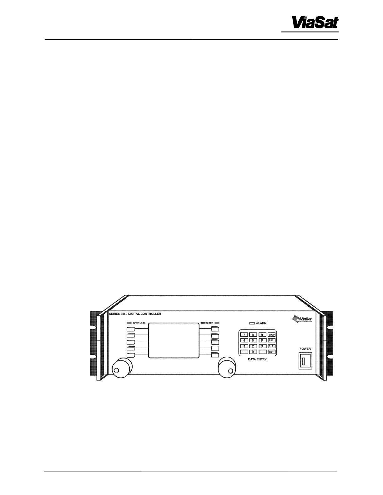
The Series 3860 of Digital Controllers (Figure 1.1) provide antenna pedestal
or positioner control in tracking, communications, and microwave
instrumentation applications. These controllers implement full digital servo loop
control and compensation in several control modes suitable for use with two-axis
pedestals and may be adapted for use with positioners having up to eight axes. The
controllers are available in a variety of physical and functional configurations to
provide maximum flexibility for any given application.
(NOTE: This illustration shows the single-chassis version.)
Figure 1.1. 3860 Digital Controller
3862 Autotrack Controller 1-2
Artisan Technology Group - Quality Instrumentation ... Guaranteed | (888) 88-SOURCE | www.artisantg.com

Chapter 1 - General Information
1.6.1 Major Components
The Digital Controller is made up of several components combined in
modular fashion to provide the desired functions and physical configuration.
Each block or module performs a unique function. For applications not
requiring a particular function, the assembly or module providing that
function may be excluded from the controller. The following are the principal
components of the Digital Controller (see Chapter 4 for detailed descriptions
of each):
• Servo Assembly
• Synchro/Resolver Assembly
• Operator/Remote Interface Assembly
• Autotrack Assembly (Optional)
• Resolver Reference Assembly
• Analog Servo Rate Loop Assembly (Optional)
• Front Panel Assembly
• Motherboard Assembly
• DC Power Supply
1.6.2 Functional Configurations
The Model 3861 Manual Controller provides basic operator control of the
pedestal. This controller is equipped with a Servo Assembly and a
Synchro/Resolver Assembly and includes the enclosures and/or interfaces
appropriate to the physical configuration selected. The Model 3861 operates
using an indoor control panel or an external computer and remote interface.
The Model 3862 Autotrack Controller includes the Autotrack Assembly
which allows operation with automated tracking systems. The automated
tracking (Autotrack) function requires input of both a signal strength and a
tracking video signal from the receiver. The Autotrack function can be used
with a wide variety of feeds and is compatible with ViaSat Satellite Networks
ESCAN and MONOSCAN tracking feeds and the associated digital
demodulation techniques.
The Model 3863 Steptrack Controller is equipped with steptrack capability
which allows operation with step tracking subsystems. The steptrack
function is contained within the Operator/Remote Interface Assembly or
within a computer subsystem equipped with the PC Interface Module. The
steptrack function requires an automatic gain control (AGC) signal from a
receiver and may be used with a wide variety of feeds.
3862 Autotrack Controller 1-3
Artisan Technology Group - Quality Instrumentation ... Guaranteed | (888) 88-SOURCE | www.artisantg.com

Chapter 1 - General Information
1.6.3 Physical Configurations
The unit may be provided with all components housed in either one or two
rack-mounted chassises as shown in Figure 1.2.
A single-chassis configuration is used in most systems. Using the singlechassis requires that all electrical control cables extend from the pedestal into
the control room and be connected directly to the 3860.
Two-chassis configurations are used in large pedestal systems where it is
possible to mount a rack-mounted chassis within the base extension. The
two-chassis configuration greatly reduces the length and number of
electrical control cables from the pedestal into the control room by placing
the functional modules that interface to the pedestal within the pedestal
equipment. The second chassis provides the operator controls and indicators.
The two chassises are functionally connected by a full-duplex fiber optic link.
The operator interface components include the keypad, display screen,
position knobs, and power switch on the front panel. The unit chassis is 5.25
inches high and can be mounted in a standard, 19-inch-wide equipment rack.
All of the Series 3860 Digital Controller's printed wiring boards provide
direct cabling access through integral connector plates on the unit's rear
panel. A fan in the rear panel provides cooling for the enclosure.
3862 Autotrack Controller 1-4
Artisan Technology Group - Quality Instrumentation ... Guaranteed | (888) 88-SOURCE | www.artisantg.com

Chapter 1 - General Information
Figure 1.2. 3860 Digital Controller Functional Configurations
3862 Autotrack Controller 1-5
Artisan Technology Group - Quality Instrumentation ... Guaranteed | (888) 88-SOURCE | www.artisantg.com
Chapter 1 - General Information
1.7 Specifications
Equipment characteristics and specifications are provided in Tables 1.1 and
1.2.
Table 1.1. Physical and Electrical Specifications
Characteristic Specification
Dimensions
Height 5.25 in. (133.35 mm)
Depth 18.00 in. (457.20 mm)
Width 19.00 in. (482.60 mm)
Weight 20 lb nominal
Input Power Requirements
Voltage 110V ac at 150W or 220V ac at 150W
Frequency 47 to 440 Hz
Host Communication Interface Serial Link
Selectable Media RS-422, RS-232, or IEEE-488
Communication Rate 9600 Baud
Controls and Indicators
Display High contrast LCD display
Mode Selection Menu-driven function keys plus full numeric
keypad
Axis Position Controls Analog position knobs and joystick for 2 axes
Status Displays Up to 32 optically isolated and 32 TTL lines to
report various system functions
Servo Functions Digital servo compensation with four user-
selectable servo loop bandwidths. Typically two
axes can be configured to control up to eight
pedestal or positioner axes
Pedestal Control Modes Standby, Rate (Slew), Position, Autotrack, Slave,
Remote and Scan
Pedestal Position Feedback Six independent synchro/resolver to digital
converters channels
3862 Autotrack Controller 1-6
Artisan Technology Group - Quality Instrumentation ... Guaranteed | (888) 88-SOURCE | www.artisantg.com
Chapter 1 - General Information
Table 1.2. Environmental Specifications
Characteristic Specification
Ambient Temperatures
Operation -0°C to +40°C (+32°F to +104°F)
Storage -20°C to +60°C (-4°F to +140°F)
Relative Humidity 0% to 95%, without condensation
Altitude
Operation 10,000 feet
Storage 50,000 feet
Cooling Fan cooling
Shock and Vibration Normal benchtop handling and commercial
shipping
1.8 Glossary of Symbols and Abbreviations
The following list defines symbols and abbreviations used in this manual.
Symbol or
Abbreviation
ABS automatic beam switching
ac alternating current
ACQTIM acquire time
A/D analog-to-digital
ADC analog-to-digital converter
AGC automatic gain control
AMPL amplitude
AUTOTRK autotrack
AUTODV auto diversity
AZ azimuth
Definition
BIT built-in test
BKMODE backup mode
C celsius
CHANN channel
CMD, CMND command
3862 Autotrack Controller 1-7
Artisan Technology Group - Quality Instrumentation ... Guaranteed | (888) 88-SOURCE | www.artisantg.com

Chapter 1 - General Information
Symbol or
Abbreviation
Definition
COMPSN compensation
CONFIG configuration
DAC digital-to-analog converter
dc direct current
DISABL disable
EL elevation
F fahrenheit
FDSCAN feed scan
FNTPNL front panel
Hz hertz
I/O input/output
kHz kilohertz
LCD liquid crystal display
LCL local
LED light-emitting diode
LCLRMT local/remote
LNCHAC launch angle
LOWTRK low track
mA milliampere
mm millimeter
MAXANG maximum angle
MINANG minimum angle
MLTPTH multipath
NS PWR noise source power
NVRAM nonvolatile RAM
ORI operator remote interface
PC personal computer
PED pedestal
PID proportional/integral/derivative
POS, POSN position
POSERR position error
POSMEM position memory
POSNFL, PFLT position filter
3862 Autotrack Controller 1-8
Artisan Technology Group - Quality Instrumentation ... Guaranteed | (888) 88-SOURCE | www.artisantg.com

Chapter 1 - General Information
Symbol or
Abbreviation
POSTIM position time
PSTART position start
PWB printed wiring board
PWR power
RAM random-access memory
RATEFL, RFLT rate filter
RCALL recall
RCVR receiver
RF radio frequency
ROM read-only memory
RTEMEM rate memory
RTETIM rate time
RUNSTP run step response
SECT sector
Definition
STAT status
STPRSP step response
STEPTR step track
STPSZE step size
TESTPT test point
THRHLD threshold
TIM DUR time duration
TQBIAS, TQB torque bias
TRAVL travel
TTL transistor-transistor logic
V volts
W watts
3862 Autotrack Controller 1-9
Artisan Technology Group - Quality Instrumentation ... Guaranteed | (888) 88-SOURCE | www.artisantg.com

Chapter 1 - General Information
Blank
3862 Autotrack Controller 1-10
Artisan Technology Group - Quality Instrumentation ... Guaranteed | (888) 88-SOURCE | www.artisantg.com

Chapter 2 - Installation
Chapter 2
Installation
2.1 Introduction
This chapter provides instructions and guidelines for installing the Series
3860 Digital Controller and for reshipment and storage as required.
2.2 Unpacking and Inspection
While unpacking, carefully compare bill of lading with equipment received.
Inspect for transit damage. If equipment is missing, carefully check and sift
through packing material to confirm. If errors are confirmed, notify ViaSat
and carrier as soon as possible.
2.2.1 Damage or Loss During Shipment
When equipment is damaged or lost in transit, the delivering transportation
company is required by law to make notation of damage or loss on the
freight bill. The carrier, not the shipper, should be charged with all damage
or loss. If damage or loss during shipping occurs, contact the carrier of the
equipment. Save the shipping carton. The carrier's inspector must examine
the carton and complete an inspection report.
2.3 Equipment Return
ViaSat makes every reasonable effort to ensure that all items arrive safely and
in working order. When equipment is received, which is not in working
order, return the equipment to the factory for repair or replacement. Return
the equipment according to the following procedure. This procedure will
apply whenever equipment is returned for warranty or other services.
a) Notify ViaSat of the problem and request a Return Material
Authorization (RMA) number and shipping instructions. For a
current list of telephone and email contact information refer to
Contact Information section of the ViaSat internet site
(http://www.viasat.com).
b) Tag or identify defective equipment and note defect and
circumstances, if any. If known, reference sales order, purchase order,
and date equipment was received.
c) Reship equipment in original shipping container or use a strong
shipping container to protect equipment during shipment.
3862 Autotrack Controller 2-1
Artisan Technology Group - Quality Instrumentation ... Guaranteed | (888) 88-SOURCE | www.artisantg.com
Chapter 2 - Installation
d) Package equipment using shock-absorbing material around all sides
of equipment.
e) Seal container securely and mark outside of container FRAGILE.
2.4 Installation Procedure
2.4.1 General
The 3860 Digital Controller indoor configuration is shipped fully assembled
and is designed to be installed in a standard 19-inch panel width equipment
rack. The unit should be mounted on chassis slides or angle chassis supports.
The controller is cooled by forced air flowing through one side and the rear
panel of the unit. The mounting location should be selected to avoid blocking
the side panel's air flow or access to the rear-panel cable connections. The
unit should not be installed adjacent to other high-heat-producing units.
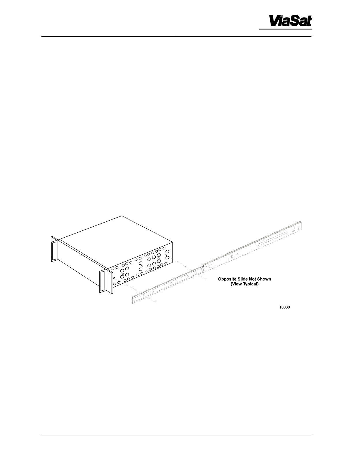
2.4.2 Chassis Slide Mounting
Two captive nuts (6-32) are provided on each chassis side panel for
attachment of chassis slides. The nut pattern matches standard chassis slides.
A typical example of slide mounting is shown in Figure 2.1.
Figure 2.1. Typical Slide Mounting
3862 Autotrack Controller 2-2
Artisan Technology Group - Quality Instrumentation ... Guaranteed | (888) 88-SOURCE | www.artisantg.com
Chapter 2 - Installation
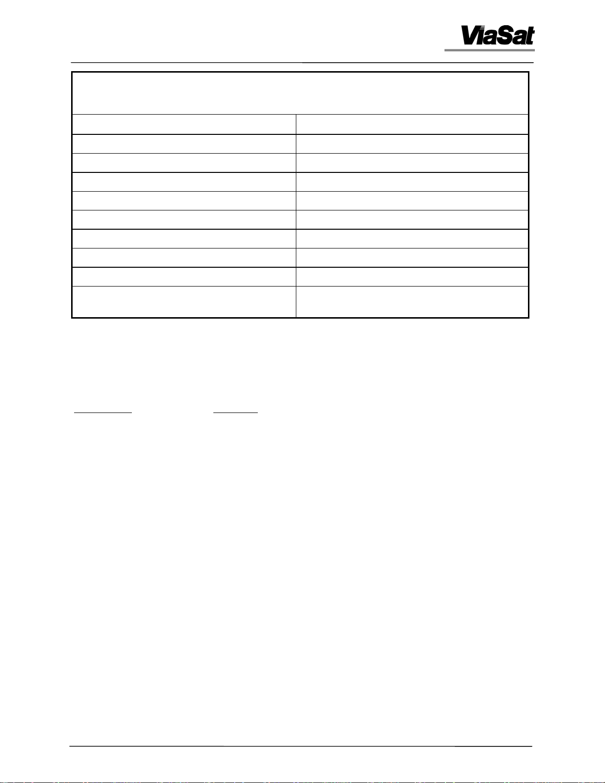
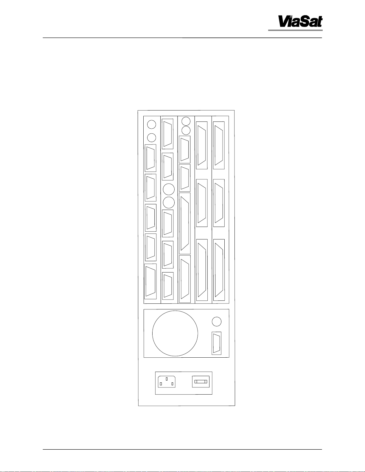
2.4.3 Cable Connectors
External cables connect directly to each component assembly on the digital
controller's rear panel. Each connector is identified by a reference designation
permanently marked on the rear panel (see Figure 2.2). A list of rear-panel
connectors with functional descriptions is provided in Table 2.1. Tables 2.2
through 2.22 provide pinout information for each connector excluding the
fiber-optic connectors. For units purchased as part of an integrated system,
refer to the appropriate system cabling diagram for cable connections.
Avoid shorting signal lines together or to chassis when
attaching cables. Equipment damage can result from failure to
observe this precaution.
CAUTION
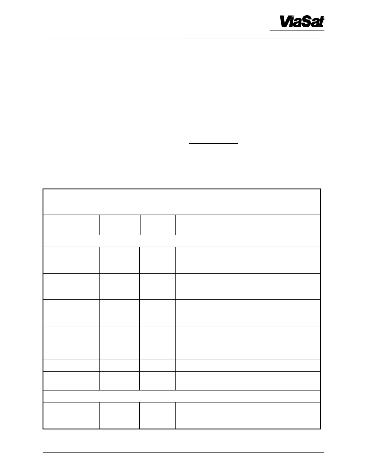
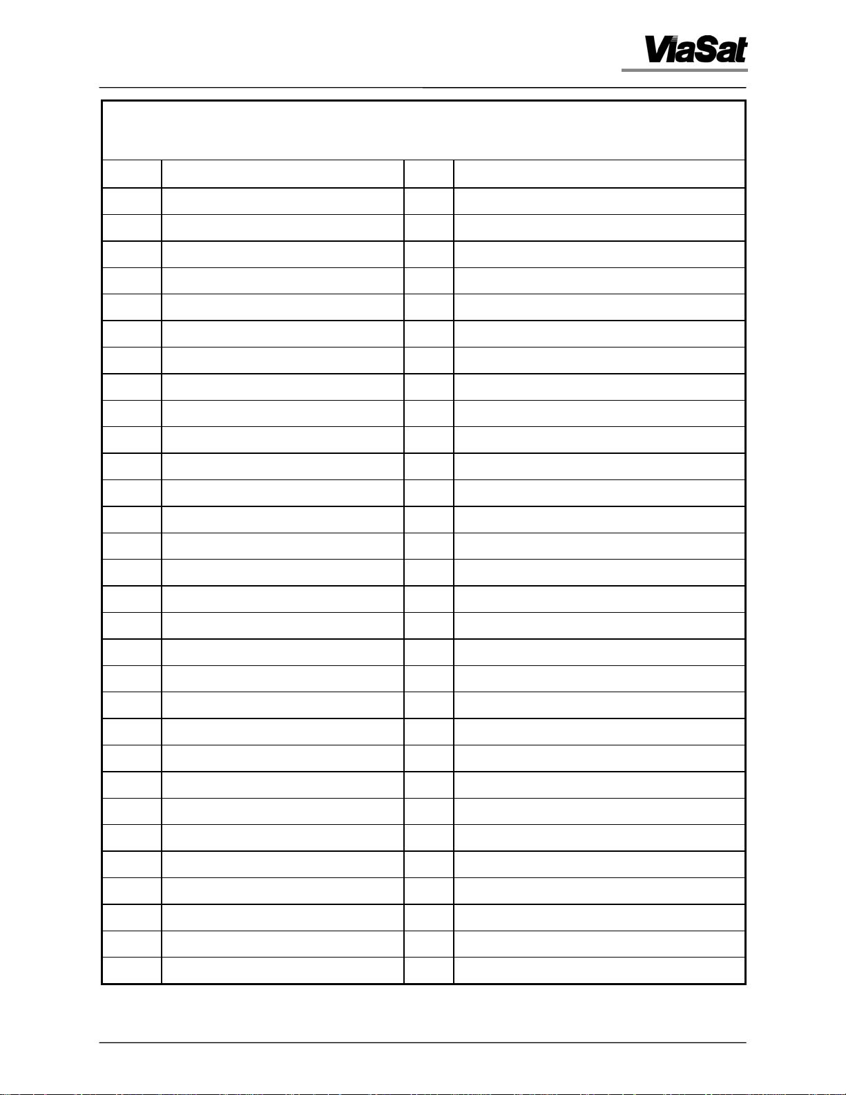
Table 2.1. 3860 Digital Controller Rear-panel Connectors
Function
Reference
Designation
Connector
Type
Interface Description
Servo Assembly
Analog I/O J101 DB25
Male
Digital I/O J102 DB62
Female
Serial Link 1 J103 DB9
Male
Serial Link 2 J104 DB9
Male
Fiber-optic Receiver J105 ST This type ST connector is a fiber-optic command link.
This connector provides tachometer signal input and
command voltage to power amplifiers. Refer to
Table 2.2 for pin assignments.
This connector provides contact closure input and
relay driver output. Refer to Table 2.3 for pin
assignments.
This connector is the main command/status link to
the operator/remote interface board. Refer to Table
2.4 for pin assignments.
This connector is the RS-422/RS-232 auxiliary/local
control data link. Refer to Table 2.5 for pin
assignments. Refer to paragraph 2.4.6 for a
description of the GPS Time-code interface.
Fiber-optic
Transmitter
J106 ST This type ST connector is a fiber-optic status
reporting link.
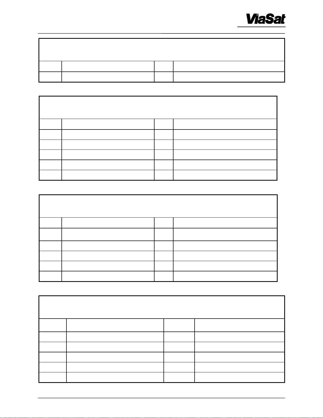
Synchro/Resolver Assembly
Synchro/Resolver
Interface
3862 Autotrack Controller 2-3
Artisan Technology Group - Quality Instrumentation ... Guaranteed | (888) 88-SOURCE | www.artisantg.com
J201 DB37
Female
This connector provides interface to resolvers or
synchros for axis position feedback or slave input.
Refer to Table 2.6 for pin assignments.
Chapter 2 - Installation
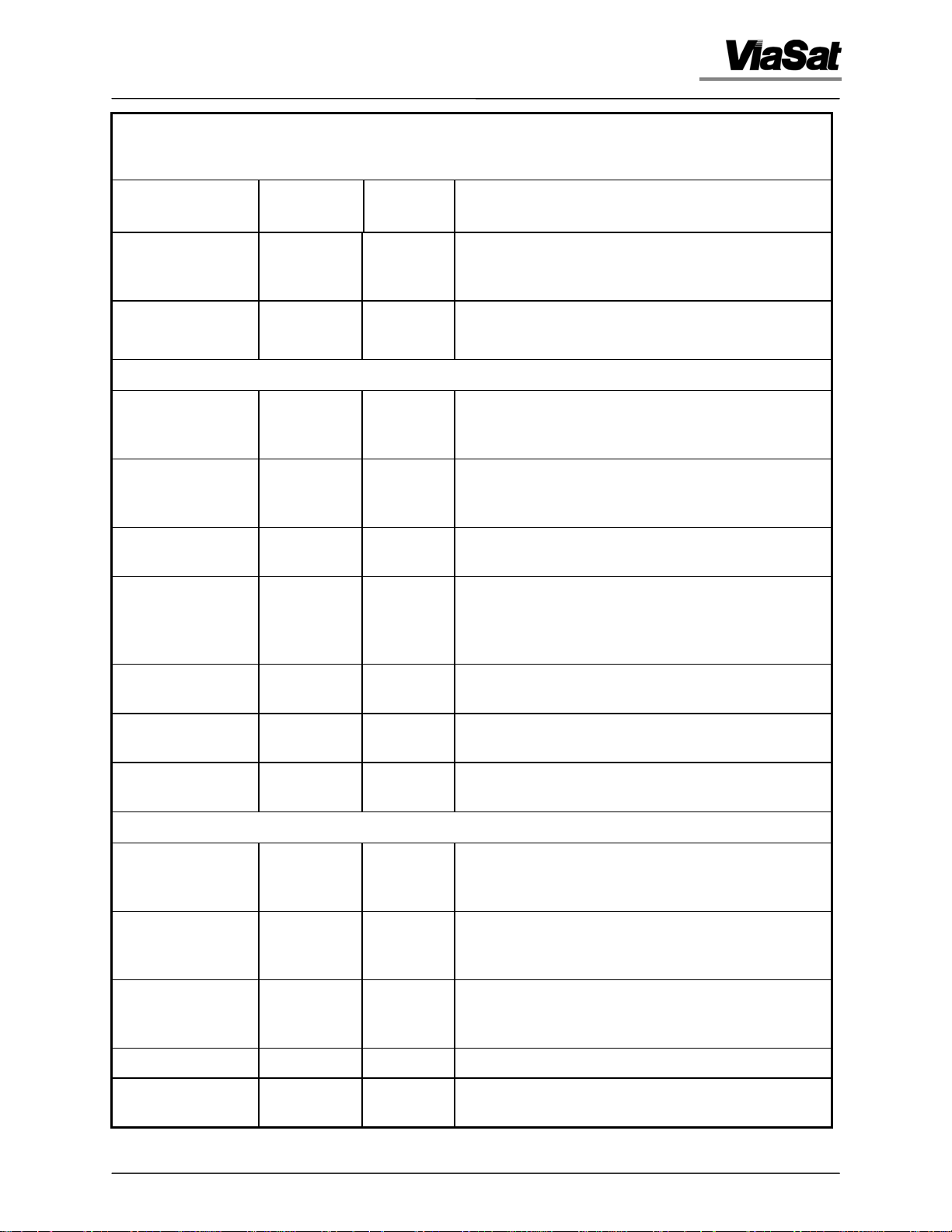
Table 2.1. 3860 Digital Controller Rear-panel Connectors
Function
Digital I/O J202 DB44
Auxiliary TTL I/O J203 DB44
Reference
Designation
Connector
Type
Female
Female
Operator/Remote Interface Assembly
IEEE-488 Remote
Interface
External Joystick J302 DB9
Analog Signals J303 DB9
Serial Port 1 J304 DB9
J301 IEEE-488
Female
Male
Male
Male
Interface Description
This connector provides contact closure sensing
inputs and relay driver outputs. Refer to Table 2.7
for pin assignments.
This connector is a configurable 32-bit TTL level I/O.
Refer to Table 2.8 for pin assignments.
This rear-panel connector provides a parallel data
interface conforming to IEEE-488-1978. Refer to Table
2.9 for pin assignments.
This connector provides connection to the table top
joystick used for az/el rate control. Refer to Table
2.10 for pin assignments.
This connector provides for AGC input for steptrack
operation. Refer to Table 2.11 for pin assignments.
This connector is the main command/status link to
the servo board. Refer to Table 2.12 for pin
assignments. Refer to paragraph 2.4.5 for a
description of the ouput data.
Serial Port 2 J305 DB9
Male
Fiber-optic Serial
Receiver
Fiber-optic Serial
Transmitter
J306 BNC This BNC connector is a fiber-optic status reporting
J307 BNC This BNC connector is a fiber-optic command link.
This connector is the link to the system computer.
Refer to Table 2.13 for pin assignments.
link.
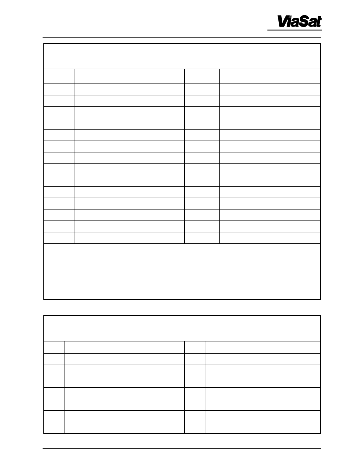
Autotrack Assembly (Optional)
Receiver 1 and 2
Video and AGC
Receiver 3 and 4
Video and AGC
Receiver 5 and 6
Video and AGC
Channel 7 AGC J404 ST This type ST connector provides AGC input.
Channel 7 Video J405 ST This type ST connector provides tracking video
J401 DB9
Male
J402 DB9
Male
J403 DB9
Male
This connector is the receiver interface containing
signal strength and tracking video. Refer to Table
2.14 for pin assignments.
This connector is the receiver interface containing
signal strength and tracking video. Refer to Table
2.15 for pin assignments.
This connector is the receiver interface containing
signal strength and tracking video. Refer to Table
2.16 for pin assignments.
input.
3862 Autotrack Controller 2-4
Artisan Technology Group - Quality Instrumentation ... Guaranteed | (888) 88-SOURCE | www.artisantg.com
Chapter 2 - Installation
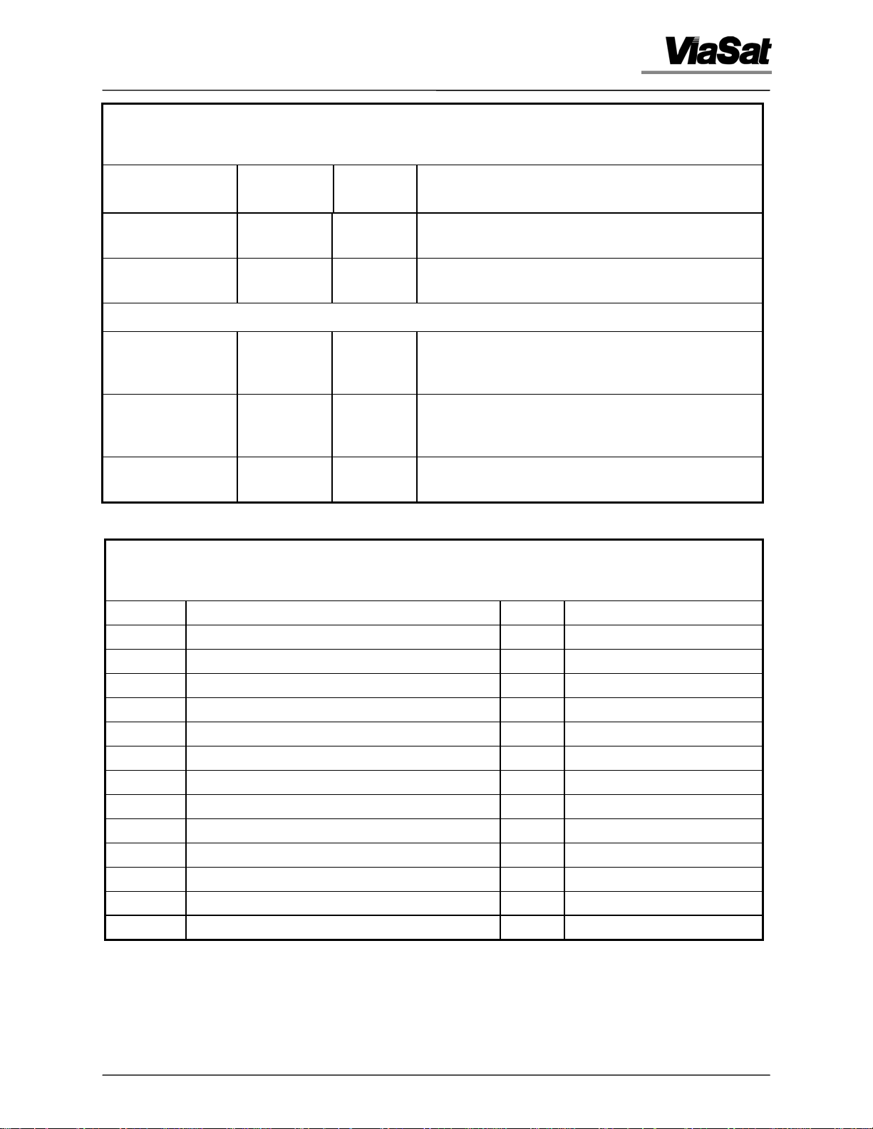
Table 2.1. 3860 Digital Controller Rear-panel Connectors
Function
Feed Scanner
Interface
Serial Link 1 J407 DB9
Reference
Designation
J406 DB9
Connector
Type
Male
Male
Analog Rate Loop Assembly (Optional)
Analog I/O J501 DB25
Female
Analog I/O J502 DB25
Male
Analog I/O J503 DB25
Female
Table 2.2. Pin Functions for J101, Analog I/O
Interface Description
This connector provides feed scan driver output.
Refer to Table 2.17 for pin assignments.
This connector is the command/status link to the
servo board. Refer to table 2.18 for pin assignments.
This connector provides input rate command from
the position loop. Refer to Table 2.19 for pin
assignments.
This connector provides tachometer signal input and
command to power amplifiers. Refer to Table 2.20 for
pin assignments.
This connector provides major test points. Refer to
Table 2.21 for pin assignments.
Pin Function Pin Function
1 GND 14 DAC6
2 AZZ TACH LO 15 DAC5
3 AGND 16 DAC4
4 AGND 17 DAC3
5 + 15 V 18 DAC2
6 Not Connected 19 DAC1
7 - 15 V 20 AMP_OUT (Test Point)
8 ADC10 21 MUX_OUT (Test Point)
9 ADC9 22 ADC4
10 ADC8 23 ADC3
11 ADC7 24 ADC2
12 ADC6 25 ADC1
13 ADC5
3862 Autotrack Controller 2-5
Artisan Technology Group - Quality Instrumentation ... Guaranteed | (888) 88-SOURCE | www.artisantg.com
Chapter 2 - Installation
E
T
O
M
E
R
/
R
O
T
A
R
E
P
O
D
D
R
R
A
O
B
E
C
A
F
R
E
T
N
I
7
0
3
J
6
0
3
J
5
0
3
J
4
0
3
J
3
0
3
J
D
A
R
O
A
B
O
K
B
C
A
O
V
R
T
R
E
O
T
S
U
A
7
0
4
J
6
0
4
J
5
0
4
J
4
0
4
J
3
0
4
J
D
R
E
A
/
O
R
H
C
N
Y
S
6
0
1
J
5
0
1
J
4
0
1
J
3
0
1
J
2
0
1
J
T
O
A
B
R
R
E
V
L
O
S
E
R
P
O
G
O
O
L
L
A
N
A
2
0
2
J
3
0
2
J
3
3
6
3
1
3
0
5
J
1
0
5
J
2
0
3
J
2
0
4
J
2
1
0
0
5
2
J
J
1
1
0
3
J
N
A
F
0
1
J
1
0
4
J
1
J
2
J
R
T
E
U
C
W
P
A
O
N
I
P
Figure 2.2. Typical Rear-panel Connector Interface
3862 Autotrack Controller 2-6
Artisan Technology Group - Quality Instrumentation ... Guaranteed | (888) 88-SOURCE | www.artisantg.com
Chapter 2 - Installation
Table 2.3. Pin Functions for J102, Digital I/O
Pin Function Pin Function
1 Pull-Up For CNTRL Output Lines 32 Not Connected
2 GND 33 Not Connected
3 GND 34 Not Connected
4 GND 35 Not Connected
5 GND 36 Not Connected
6 GND 37 Not Connected
7 External Pull-Up 38 Not Connected
8 Not Connected 39 Cmnd01
9 STAT16 40 Cmnd02
10 STAT15 41 Cmnd03
11 STAT14 42 Cmnd04
12 STAT13 43 Cmnd05
13 STAT12 44 Cmnd06
14 STAT11 45 Cmnd07
15 STAT10 46 Cmnd08
16 STAT09 47 Not Connected
17 STAT08 48 Not Connected
18 STAT07 49 Not Connected
19 STAT06 50 Not Connected
20 STAT05 51 Not Connected
21 STAT04 52 Not Connected
22 STAT03 53 Not Connected
23 STAT02 54 Not Connected
24 STAT01 55 Not Connected
25 Not Connected 56 Not Connected
26 Not Connected 57 Not Connected
27 Not Connected 58 Input Pull-Up For Stat09 - Stat16 Lines
28 Not Connected 59 Not Connected
29 Not Connected 60 Input Pull-Up For Stat08 - Stat01 Lines
30 Not Connected 61 Not Connected
3862 Autotrack Controller 2-7
Artisan Technology Group - Quality Instrumentation ... Guaranteed | (888) 88-SOURCE | www.artisantg.com
Chapter 2 - Installation
Table 2.3. Pin Functions for J102, Digital I/O
Pin Function Pin Function
31 Not Connected 62 Not Connected
Table 2.4. Pin Functions for J103, Serial Link 1
Pin Function Pin Function
1 GND 6 +RX1 RS-422
2 TX1 RS-232 7 Not Connected
3 –TX1 RS-422 8 RX1 RS-232
4 –RX1 RS-422 9 +TX1 RS-422
5 GND
Table 2.5. Pin Functions for J104, Serial Link 2
Pin Function Pin Function
1 CTS2 RS-232 6 +RX2 RS-422
2 TX2 RS-232 7 Not Connected
3 –TX1 RS-422 8 RX2 RS-232
4 –RX1 RS-422 9 +TX2 RS-422
5 GND
Table 2.6. Pin Functions for J201, Synchro/Resolver Interface
Pin Function Pin Function
1 Resolver Reference – 20 Resolver Reference +
2 Not Connected 21 S64 (Channel 6 Lead S4)
3 S63 (Channel 6 Lead S3) 22 S62 (Channel 6 Lead S2)
4 S61 (Channel 6 Lead S1) 23 Not Connected
5 S54 (Channel 5 Lead S4) 24 S53 (Channel 5 Lead S3)
3862 Autotrack Controller 2-8
Artisan Technology Group - Quality Instrumentation ... Guaranteed | (888) 88-SOURCE | www.artisantg.com
Chapter 2 - Installation
Table 2.6. Pin Functions for J201, Synchro/Resolver Interface
Pin Function Pin Function
6 S52 (Channel 5 Lead S2) 25 S51 (Channel 5 Lead S1)
7 Not Connected 26 S44 (Channel 4 Lead S4)
8 S43 (Channel 4 Lead S3) 27 S42 (Channel 4 Lead S2)
9 S41 (Channel 4 Lead S1) 28 Not Connected
10 S34 (Channel 3 Lead S4) 29 S33 (Channel 3 Lead S3)
11 S32 (Channel 3 Lead S2) 30 S31 (Channel 3 Lead S1)
12 Not Connected 31 S24 (Channel 2 Lead S4)
13 S23 (Channel 2 Lead S3) 32 S22 (Channel 2 Lead S2)
14 S21 (Channel 2 Lead S1) 33 Not Connected
15 S14 (Channel 1 Lead S4) 34 S13 (Channel 1 Lead S3)
16 S12 (Channel 1 Lead S2) 35 S11 (Channel 1 Lead S1)
17 Not Connected 36 Not Connected
18 Not Connected 37 Synchro Reference
19 Synchro Reference +
Standard Channel Designations:
Channel 1 — Azimuth Coarse
Channel 2 — Azimuth Fine
Channel 3 — Elevation Coarse
Channel 4 — Elevation Fine
Channel 5 — Azimuth Slave
Channel 6 — Elevation Slave
Table 2.7. Pin Functions for J202, Digital I/O
Pin Function Pin Function
1 STAT21 23 STAT31
2 STAT17 24 CMND17
3 CMND10 25 CMND19
4 CMND12 26 CMND21
5 CMND14 27 CMND23
6 CMND16 28 STAT25
7 STAT30 29 STAT27
3862 Autotrack Controller 2-9
Artisan Technology Group - Quality Instrumentation ... Guaranteed | (888) 88-SOURCE | www.artisantg.com
 Loading...