

Page 1
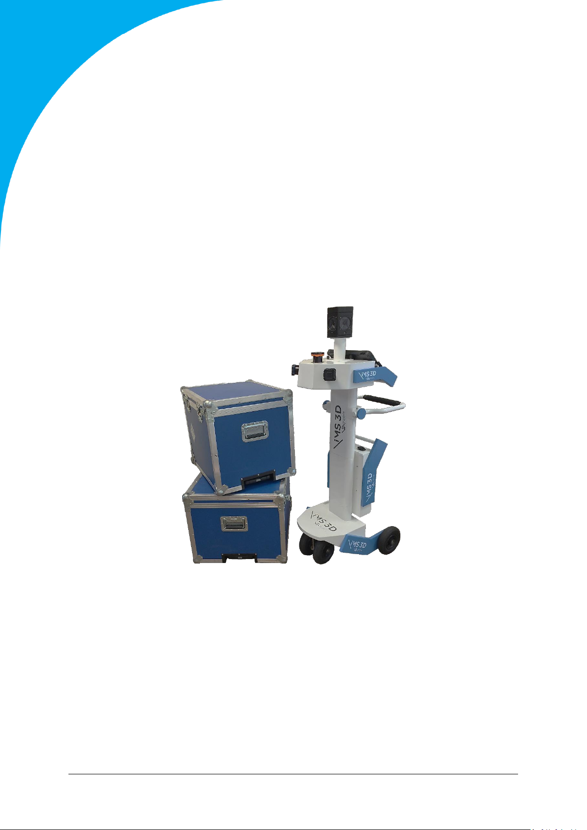
Version
Current iMS3D version
Date
Document v2.12
iMS3D – iMMSv2e
December 2017
iMS3D
Operating Guide
VIAMETRIS
Koï Center – Bd de la Communication – 53950 Louverné – France
Page 2

iMS3D – Indoor Mobile Scanning System
Operating Guide. © Viametris SAS.
CONTENT
1 INTRODUCTION & PRELIMINARY 4
1.1 NORMAL CONDITIONS 4
1.2 COMPONENT LISTS 4
2 MOUNT YOUR SYSTEM 5
3 START SCANNING 9
4 DATA TRANSFER 12
5 RECHARGING THE TABLET ON BOARD 13
6 SWITCH-OFF AND BOX STORING 13
7 SYSTEM VEC FILE 16
7.1 MEANING 16
7.2 HOW TO UPDATE IT 16
8 USAGE RECOMMENDATIONS 16
8.1 SITE PREPARATION 16
8.2 OPERATIONAL RECOMMENDATIONS 16
8.2.1 GENERAL ADVISES ON SCOUT ROLE AND POSITIONING; 17
8.2.2 LIGHT CONDITIONS: 18
8.2.3 ARCHITECTURAL CONDITIONS: 20
8.2.4 DOORS: HOW TO HANDLE “OPEN/CLOSE” 22
8.2.5 HOW TO HANDLE BUSY ROOMS (FURNITURE/STORAGE) 23
8.2.6 RAMP UP/DOWN 23
8.2.7 HOW TO MOVE THE CART AND TRAJECTORY. 25
8.2.8 TRAFFIC ON THE FLOOR. 25
8.2.9 STAIRWAYS RELATED RECOMMENDATIONS 26
8.2.10 CELLARS AND MANSARD ROOFED ATTICS: 26
8.2.11 USAGE OF VIAMETRIS TARGETS 27
8.2.12 USAGE OF PAUSE VS STOP (WHEN TO DO, PRECAUTIONS TO TAKE) 27
9 SAFETY RECOMMENDATIONS: 28
10 TRADEMARKS 28
11 SITE CHECK LIST 29
iMS3D – Operating Guide Document v2.12 2
Page 3

iMS3D – Indoor Mobile Scanning System
Operating Guide. © Viametris SAS.
12 TROUBLESHOOTING 30
13 TABLE OF FIGURES. 31
iMS3D – Operating Guide Document v2.12 3
Page 4
iMS3D – Indoor Mobile Scanning System
Operating Guide. © Viametris SAS.
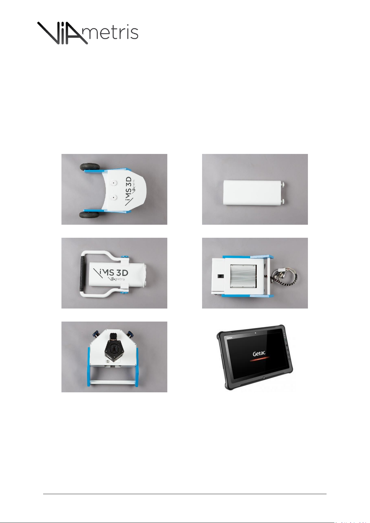
Figure 1: Roller frame
Figure 2: Mast Frame #1
Figure 3: Mast frame #2 including the handle
Figure 4: Processing unit
Figure 5: Sensor unit
Figure 6: Rugged Tablet & charger
1 INTRODUCTION & PRELIMINARY
1.1 NORMAL CONDITIONS
iMS3D stands for “indoor Mobile Scanning” and 3D for “3D point cloud”. We remind the user that the
iMS3D is a surveying equipment dedicated to indoor jobs and mainly for building areas. Indeed, the
iMS3D has been build and designed for such environment and every sensor, mechanics and electronic
components has been chosen in order to fit the building measurement requirements.
1.2 COMPONENT LISTS
iMS3D – Operating Guide Document v2.12 4
Page 5
iMS3D – Indoor Mobile Scanning System
Operating Guide. © Viametris SAS.
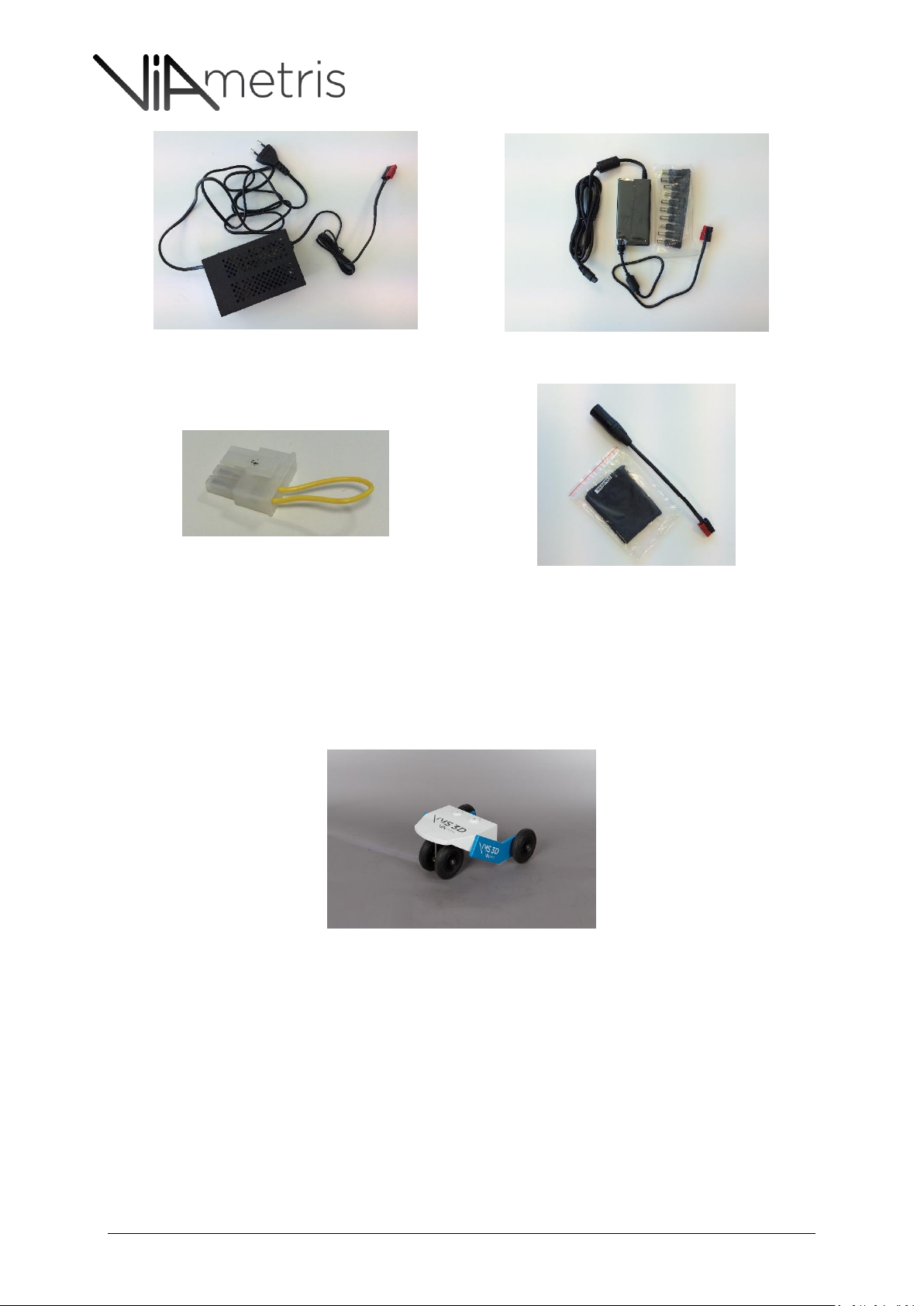
Figure 7: System Charger
Figure 8: Embedded Tablet charger: this one should be
used when scanning
Figure 9: MOLEX connector to activate the battery
Figure 10: XLR connector used for chargers to be connected
to the processing unit
2 MOUNT YOUR SYSTEM
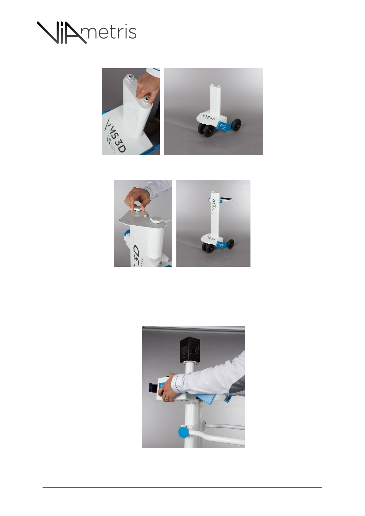
1. Open the boxes and start with the one which contains the kart
2. Put the roller frame on the floor
iMS3D – Operating Guide Document v2.12 5
Page 6
iMS3D – Indoor Mobile Scanning System
Operating Guide. © Viametris SAS.
3. Select the next Mast frame #1 and screw it on the roller
4. Select the next Mast frame and screw it using the same method:
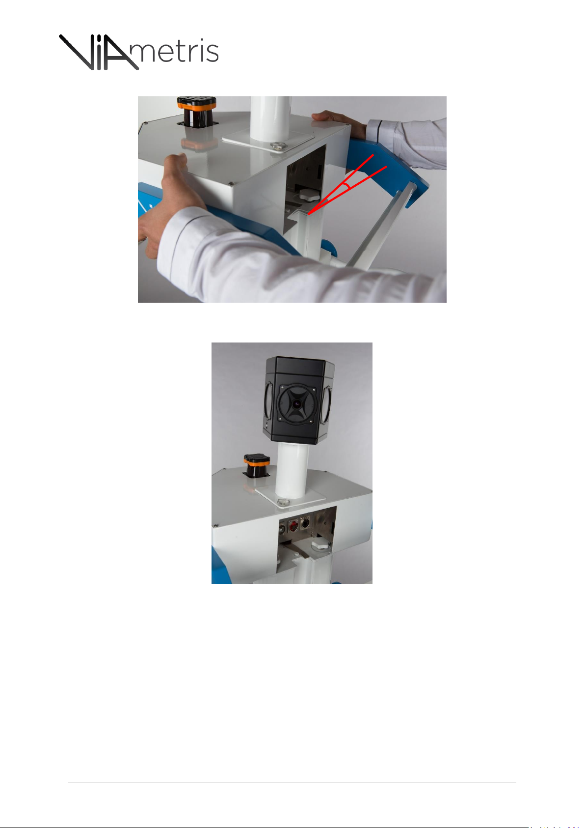
5. Mount the camera frame on the sensor unit – the Ladybug camera gets six (6) different
cameras spread on a pentagon: Five (5) all around and one (1) on the top.
THE CAMERA INDEX #0 MUST BE ORIENTED FORWARD
6. Mount the unit on the frame
7. The sensor unit needs to be placed with a 15 degrees angle with respect to the frame
iMS3D – Operating Guide Document v2.12 6
Page 7
iMS3D – Indoor Mobile Scanning System
Operating Guide. © Viametris SAS.
8. Once the sensor unit is placed on the frame, turn it sharply to lock the sensor unit on the frame
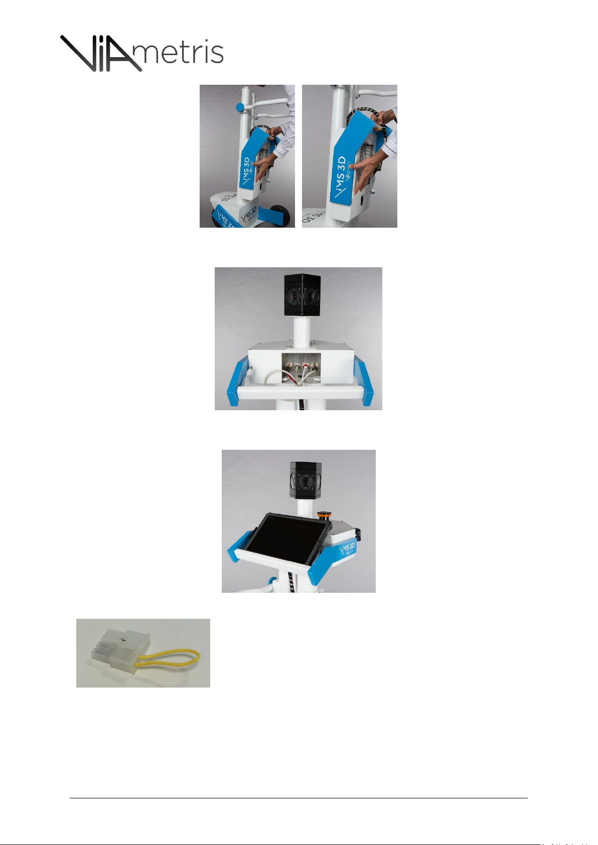
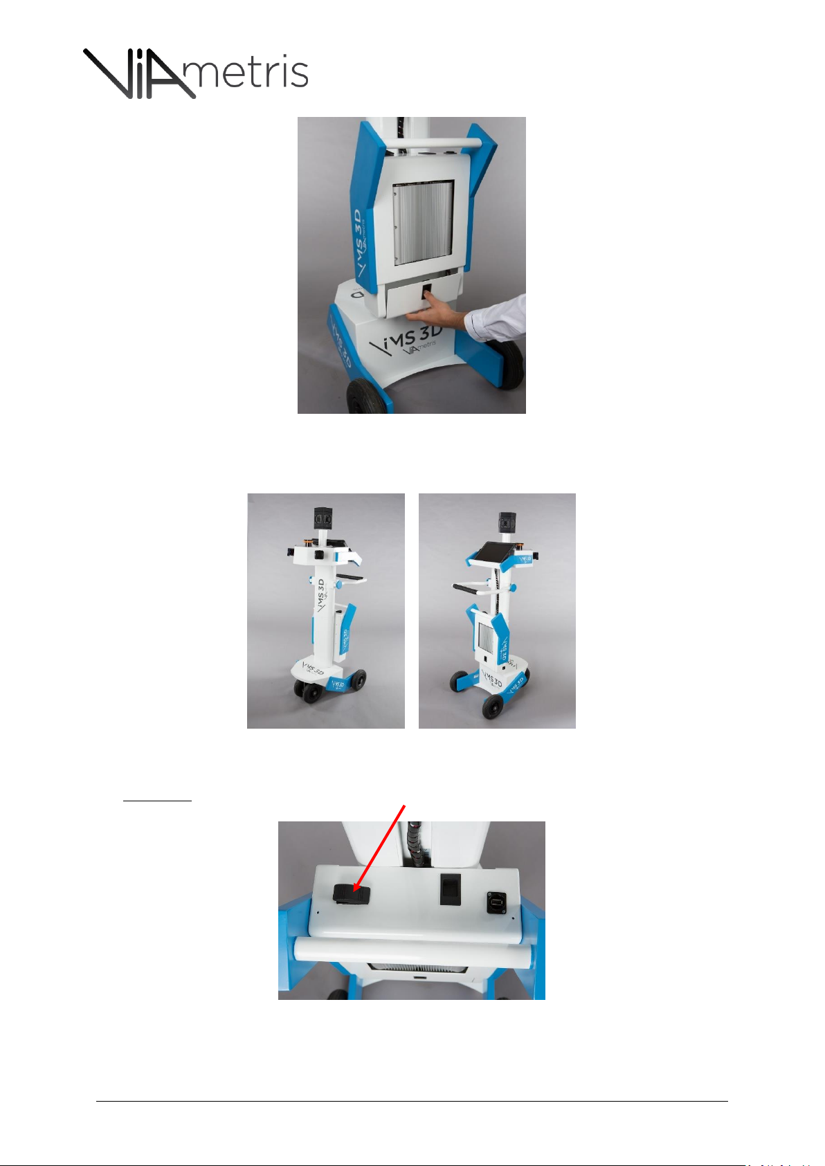
9. Install the processing unit using by facing the three plastic hooks to the holes in the mast frame
iMS3D – Operating Guide Document v2.12 7
Page 8
iMS3D – Indoor Mobile Scanning System
Operating Guide. © Viametris SAS.
For safety reason, VIAMETRIS disconnect the battery “molex” connector. This is a
hardware switch which disconnect the battery since this molex is not plugged.
Then, your first start requires you to open the battery compartment under the
computer (Processing unit) and plug the molex to the battery.
10. Plug every cable to the sensor unit. No confusion is possible.
11. You can plug the tablet using the USB3 to Ethernet device and put the tablet on the stand
iMS3D – Operating Guide Document v2.12 8
Page 9
iMS3D – Indoor Mobile Scanning System
Operating Guide. © Viametris SAS.
3 START SCANNING
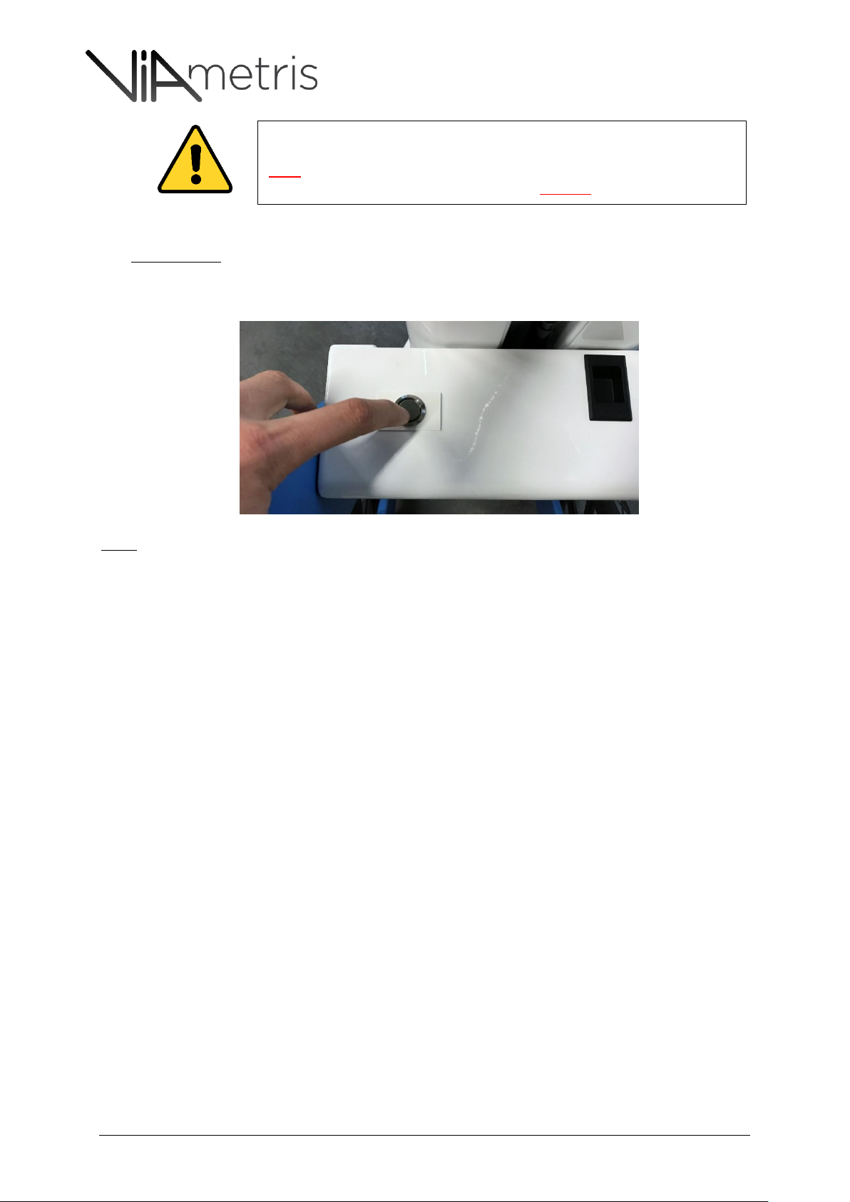
1- POWER ON THE SYSTEM
FIRST CASE - Switch on the system by pressing the Black switch on the processing unit’s top
iMS3D – Operating Guide Document v2.12 9
Page 10
iMS3D – Indoor Mobile Scanning System
Operating Guide. © Viametris SAS.
All the iMS3D version with serial number prefix iMMSv2a, iMMSv2b, iMMSv2c
and iMMSv2d are designed without power control board. It means that the user
must respect the process to power off the system.
Otherwise, the embedded computer could be DAMAGED
SECOND CASE – From system version “iMMSv2e”, the system embeds power control board with
a different switch: non-permanent Push Button with blue light circle. Push the button at least one
second until the light is flashing
Note:
Then, the blue light is flashing every second until the system has properly started - Once initialized and ready to go,
the light is on.
By switching on the system, the computer will beep, the profilers will start with LEDs and the camera will have one
Green/Orange LED on.
iMS3D – Operating Guide Document v2.12 10
Page 11
iMS3D – Indoor Mobile Scanning System
Operating Guide. © Viametris SAS.
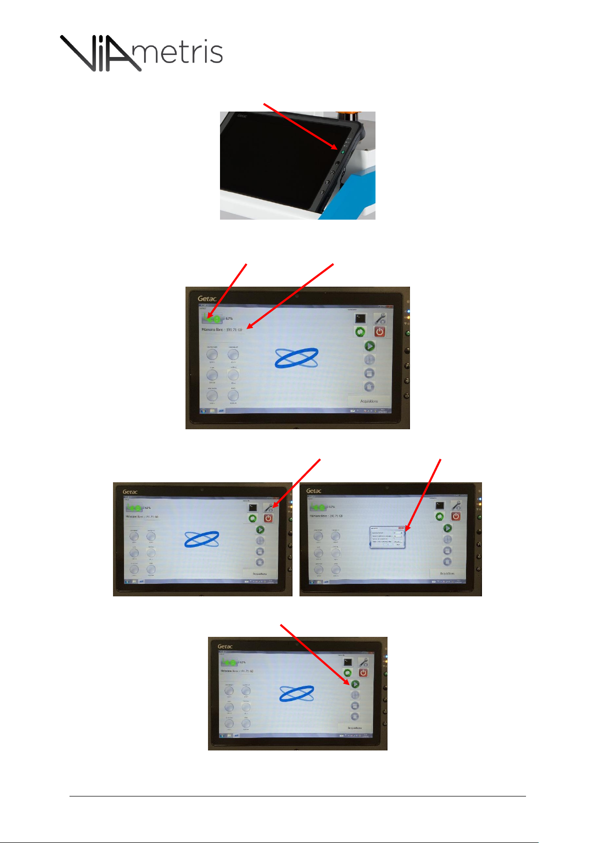
2- Power on the tablet by pushing the green button
3- Launch the iMS3D program on the tablet and wait for connection with the embedded
computer. The System battery level and the free disk space on the embedded computer is
displayed.
4- It is possible to change the image trigger distance: by default, the value is 2m, meaning that a
new image is grabbed every two (2) meters
5- Start the acquisition by clicking the “Play” button
iMS3D – Operating Guide Document v2.12 11
Page 12
iMS3D – Indoor Mobile Scanning System
Operating Guide. © Viametris SAS.
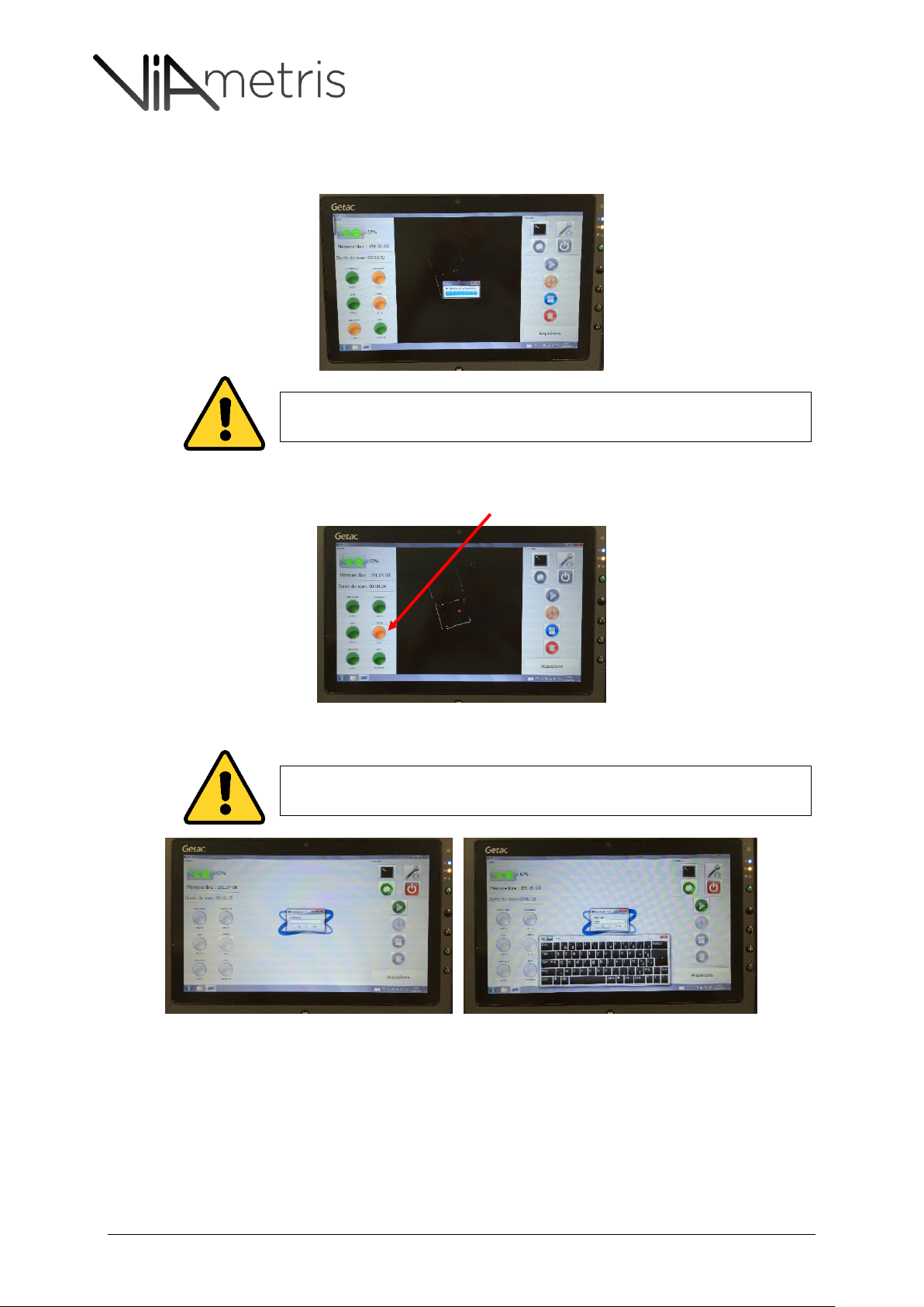
A window pops up and informs the user to not move the equipment. This static
position is required during five (5) seconds.
A window pops up and informs the user to not move the equipment. This static
position is required during five (5) seconds.
6- The map appears and every sensor starts… the status of each sensor is displayed on the left by
six (6) lights
7- The camera status is mainly orange (no image is grabbed) and blinks green once new image is
grabbed. The user can force and is able to trig manually by clicking the camera status light
8- When terminated, stop the acquisition and enter a comment if you want to. Press enter.
4 DATA TRANSFER
Once one or several acquisitions have been done, it is necessary to export the dataset.
iMS3D – Operating Guide Document v2.12 12
Page 13
iMS3D – Indoor Mobile Scanning System
Operating Guide. © Viametris SAS.
1
The scan data is recorded on the Processing unit’ embedded computer. It means
that the tablet needs to be connected to the system to be able to export the
dataset.
It is very important that the embedded computer power off properly. Then, as we
previously attracted the user’s attention, the system may not be equipped with a
power manager, depending on which version.
Then, it is expressly required to switch off the system through the tablet program.
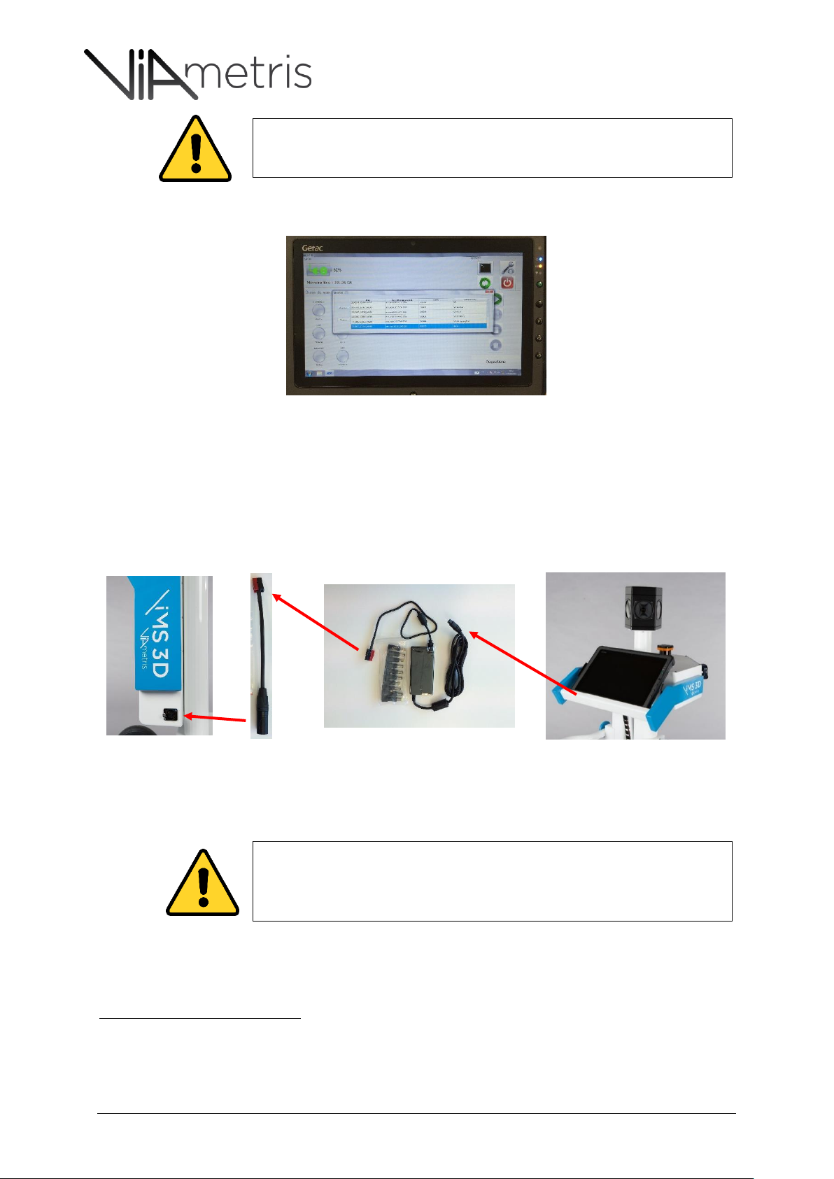
Click on the “Acquisitions” button and select one or several scans at once. Then, click on “Export”.
It is possible to export with a higher compression rate but this will increase the export time.
Finally, the exported file is an archive with the AAR extension, meaning Acquisition ARchive.
This file can be copied and moved anywhere to be processed into PPiMMS1.
5 RECHARGING THE TABLET ON BOARD
The system is able to charge the tablet’s battery thanks to an on-board charger:
6 SWITCH-OFF AND BOX STORING
Post processing software is dedicated to calculate trajectories and compute 3D point cloud. Please refer to the
PPiMMS manual to import the AAR file.
iMS3D – Operating Guide Document v2.12 13
Page 14
iMS3D – Indoor Mobile Scanning System
Operating Guide. © Viametris SAS.
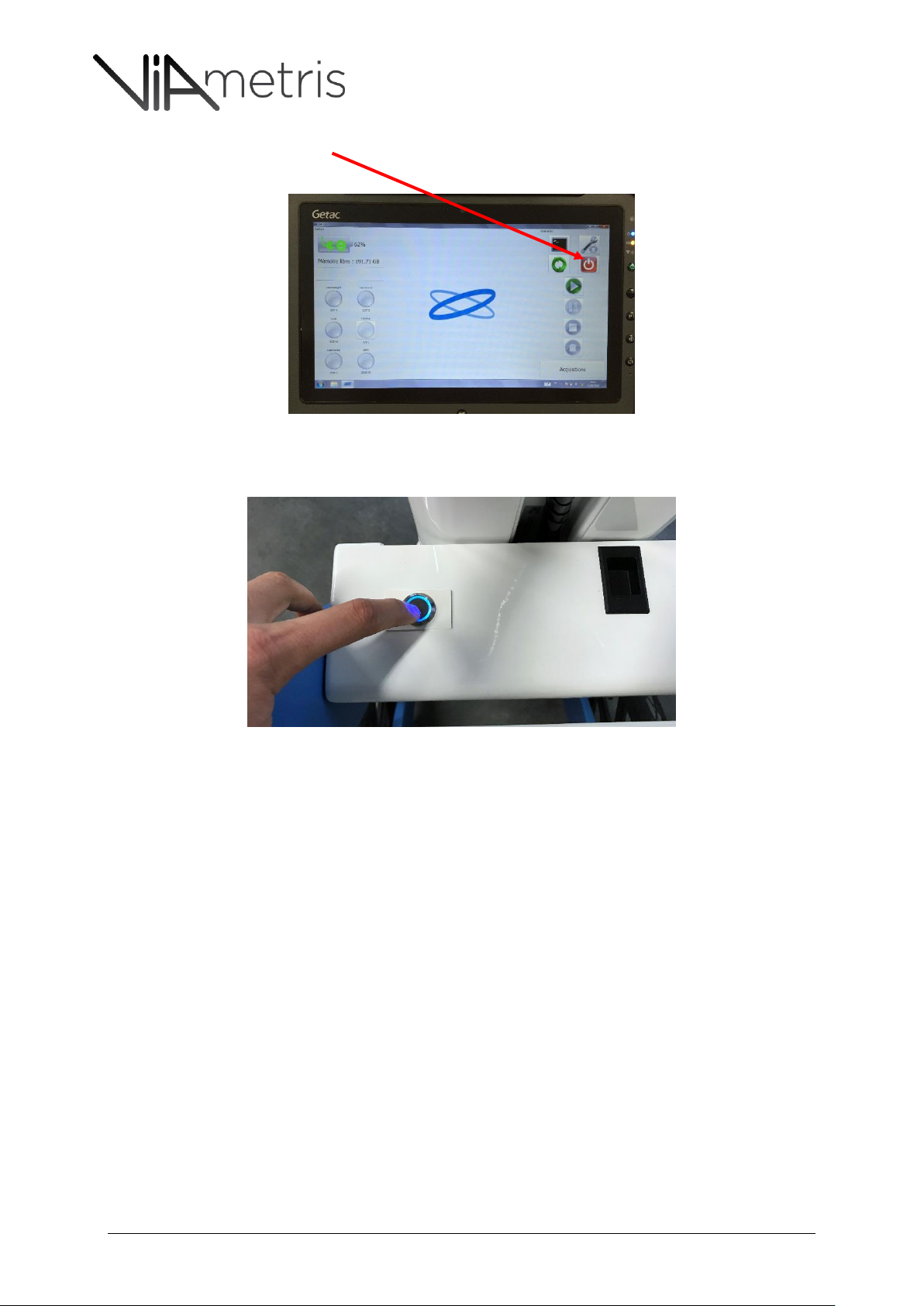
On the tablet, click on the power button to close it. A window will pop up to inform that the embedded
computer will shut down.
From system version above “iMMSv2e”, the user can also switch off the system by pushing on the
Push-button.
iMS3D – Operating Guide Document v2.12 14
Page 15
iMS3D – Indoor Mobile Scanning System
Operating Guide. © Viametris SAS.
Note:
When the user click the push button to switch off, the blue light flashes until the system is completely off.
If the user switches off the system from the tablet, the blue light of the switch flashes as well.
Then, every component should be removed at the exact inverted order than the one used to mount it.
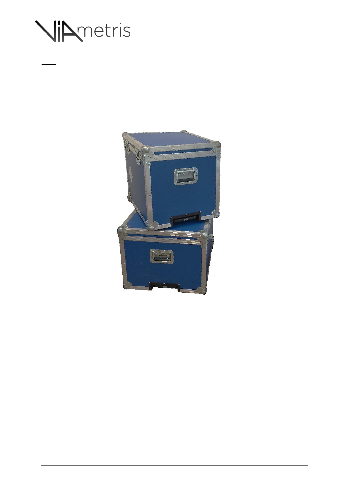
The flight cases are designed to store the components in this order.
iMS3D – Operating Guide Document v2.12 15
Page 16

iMS3D – Indoor Mobile Scanning System
Operating Guide. © Viametris SAS.
7 SYSTEM VEC FILE
7.1 MEANING
The internal VEC file which is inside the system is dedicated to every system. It gathers the calibration
parameters. This file cannot be exchanged with another one or modified by any one.
Usually, this file is produced by VIAMETRIS team and as no reason to change but in case of shocks or
physical changes in the sensor unit.
7.2 HOW TO UPDATE IT
In case VIAMETRIS team send a new VEC file, the user is able to update it through the tablet:
First switch-on the system and the tablet
Wait for the connection between the system and the tablet
Enter the configuration window
Update configuration file and select the new file
8 USAGE RECOMMENDATIONS
8.1 SITE PREPARATION
Inspect scan surface, make sure to scan in an even floor or less rough as possible to prevent
from unexpected vibration
Scout your scanning area to anticipate your trajectory.
Open each door to facilitate your scan.
Lit up each room to ensure a good camera shooting
Ensure proper access to all rooms and areas targeted (key locks, pin locks) as well as the
room’s availability for scanning operations. (Meetings…)
Further recommendations about scout’s role and trajectory are provided in the next section 8.2
8.2 OPERATIONAL RECOMMENDATIONS
iMS3D is a highly performing system using state of the art technology components. Nevertheless there
are some basic precautions to be undertaken considering:
- The Hokuyo® profilers are designed for indoor measurement, direct sun light will decrease the
measurement ranges.
- Ladybug® camera works with a shutter time and going through different light conditions will
produce either dark or white images during transitions.
- Central Hokuyo® profiler needs to scan vertical features.
- Despite highly sophisticated algorithms, measurements can be altered by wrong scanning staff
positioning (see section on Scout 8.2.1)
Therefore, it is key that the following operational recommendations are implemented as they are
critical to obtain optimum measurements.
iMS3D – Operating Guide Document v2.12 16
Page 17
iMS3D – Indoor Mobile Scanning System
Operating Guide. © Viametris SAS.
Glass wall
Intense
terraces
Stairways
& lifts
Crowded
storage room
Dark closet
room
Door steps
Long corridor
features
Intense
external blinds
Ramps
Vaulted
Role of
Scout
Long corridor
features
Trajectory
Intense
internal blinds
Mirrors
Ramps
daylight with
with
distinctive
without
distinctive
daylight with
daylight on
Ceilings
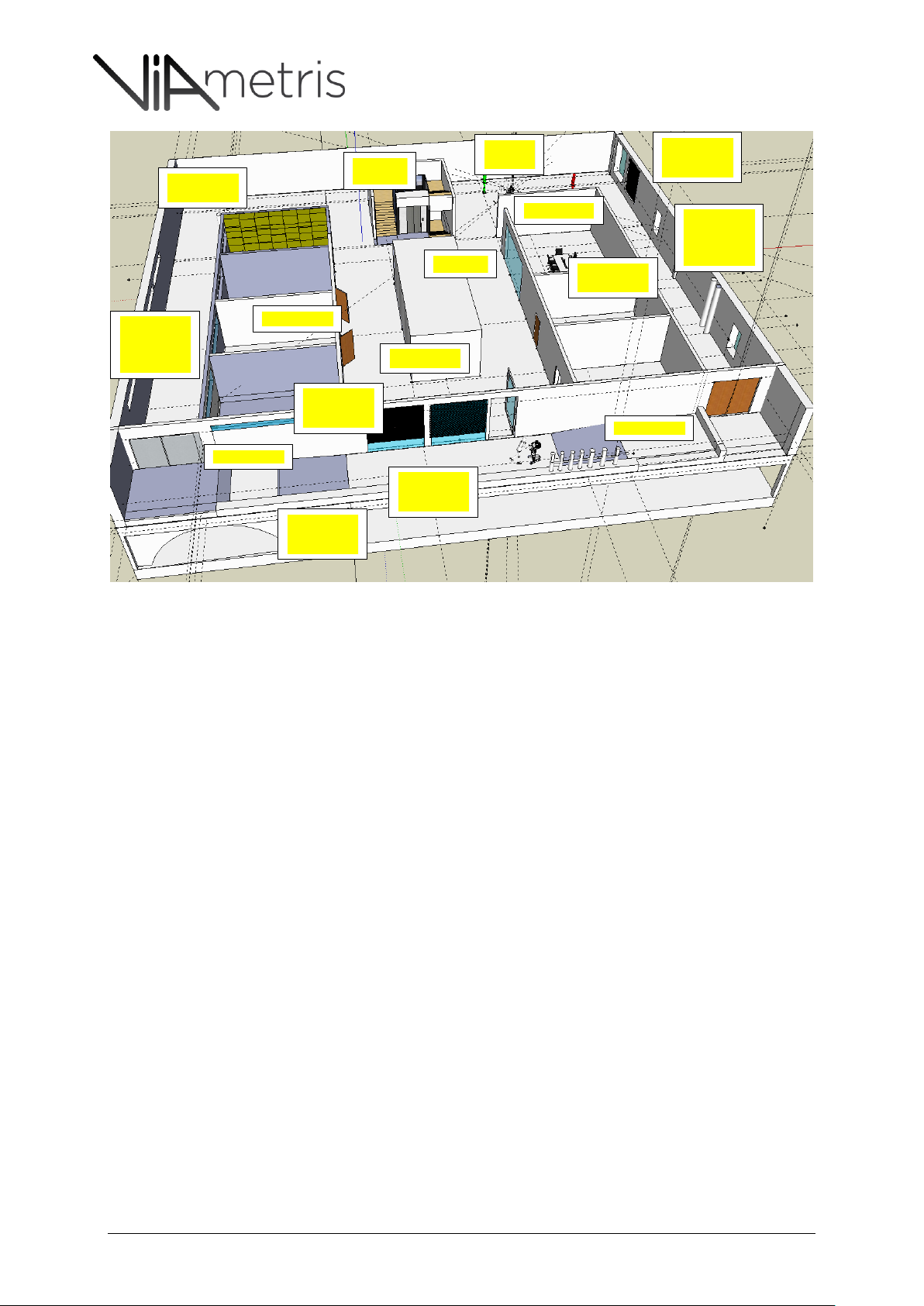
Figure 11:overall recommendations for some real life situations.
8.2.1 GENERAL ADVISES ON SCOUT ROLE AND POSITIONING;
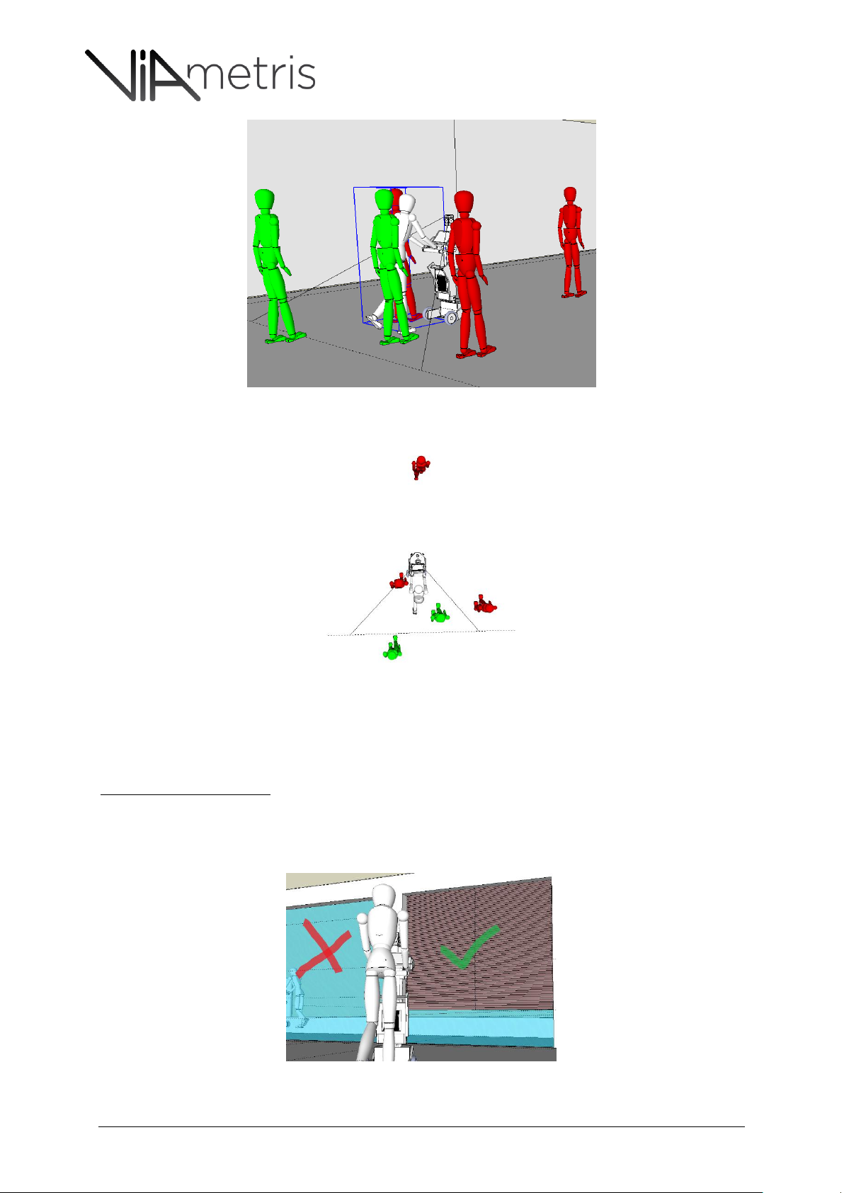
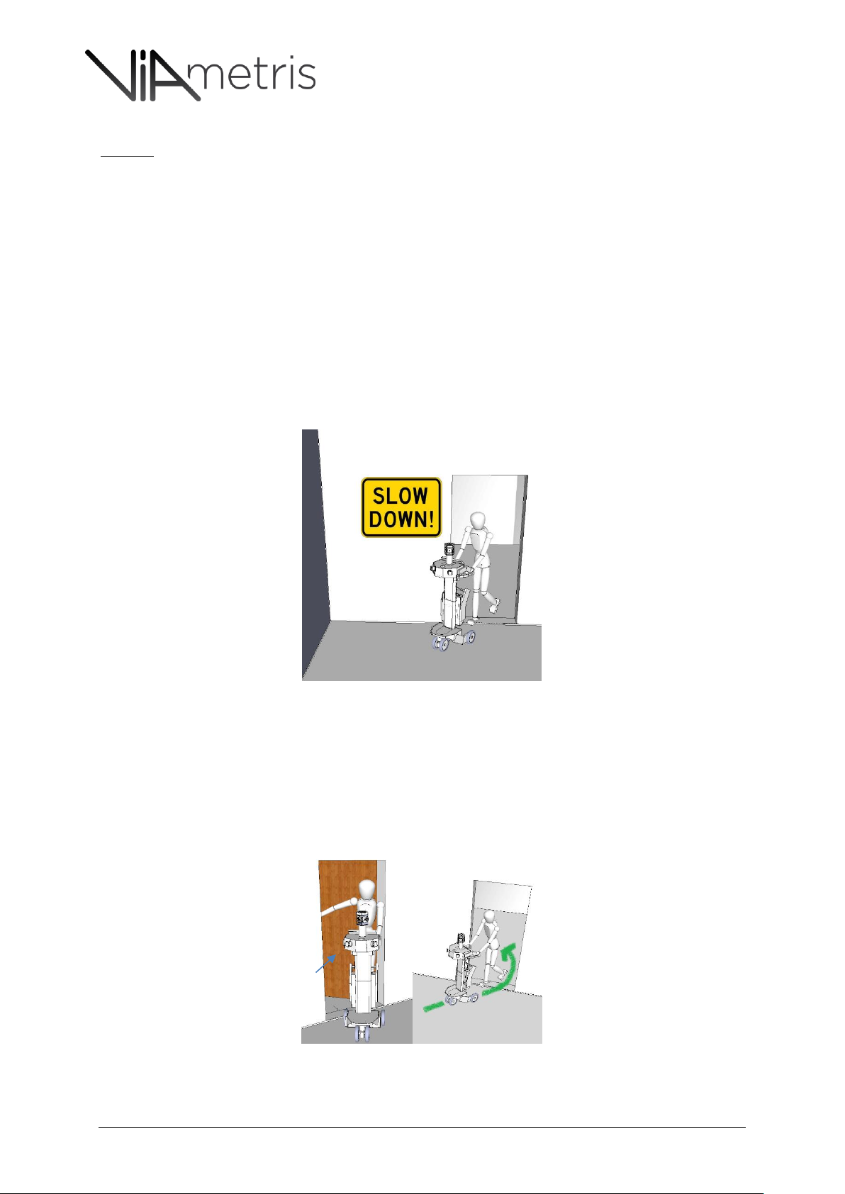
Avoid to remain in front of the cart or by the cart side. (see the 270° scan angle in Figures 12
& 13)
Facilitate the doors/light handling in front of the cart trajectory (enough in advance not to
interfere with measurement).
To avoid the scout to be caught within the scan range, it is recommended that the scout
prepare the room in advance and not “just in front” of the cart
Warn staff and visitors of the presence of the scanning operations, but they should not change
their trajectory if they come across the cart.
In case the Scout is “caught” in the scan range, it is recommended that he remains still, till he
finds himself behind the cart and then can resume his activities.
Kindly explains to site guide or demo attendees to remain behind the cart as their permanent
presence by the side of the cart would create a ghost wall.
iMS3D – Operating Guide Document v2.12 17
Page 18
iMS3D – Indoor Mobile Scanning System
Operating Guide. © Viametris SAS.
Figure 12:the scout has to remain out of the front scan range (270°), same advise goes with “support” staff or demo
attendees, who should not walk aside the operator but behind (within the remaining 90° spot). Red is wrong, green is OK
Figure 13: the scout has to remain out of the front scan range (270°). Red is wrong, green is OK
8.2.2 LIGHT CONDITIONS:
Profilers and Cameras imbedded are very sensitive to light.
Intense sun light exposure
When a room is very exposed to direct sun light:
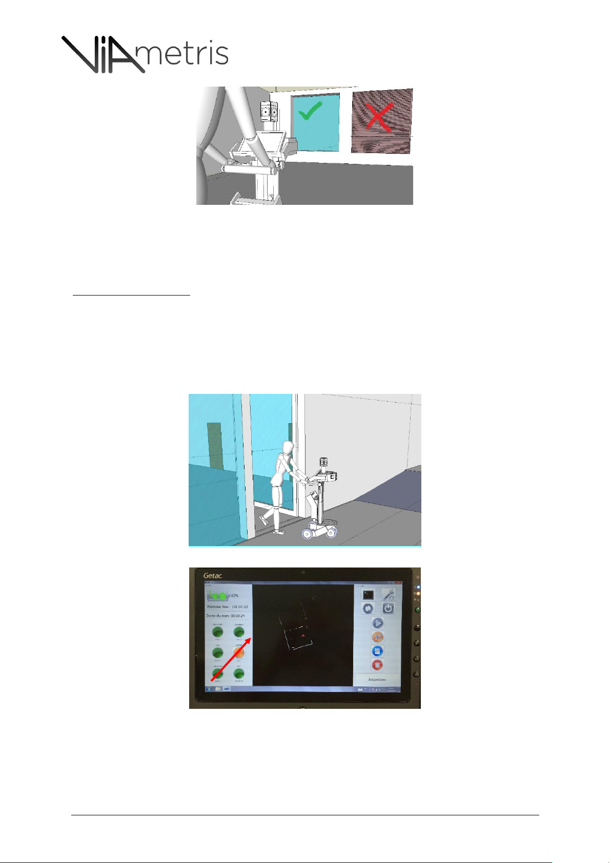
o If external blinds are available: have them shut down. (see Figure 14)
o If only internal blinds or curtains are available, leave them opened as they could hide
important windows details.(see Figure 15)
Figure 14: external blinds have to be closed down as they don’t hide important details.
iMS3D – Operating Guide Document v2.12 18
Page 19
iMS3D – Indoor Mobile Scanning System
Operating Guide. © Viametris SAS.
Figure 15: internal blinds have to be left opened as they hide important details.
If intense light exposure cannot be avoided in a room then the measurement distances have
to be shorter and the scanning trajectory has to be closer to scanned objects.
Failure to respect this recommendations leads to noisy laser measurements)
Light exposure variations
When moving from a corridor with neon light to a dark room with very low light (i.e. no window
closet)
When moving from a normally exposed room to a very bright light environment (i.e. a balcony
or a terrace) See Figure 16
To avoid under exposed or over exposed pictures, it is recommended to pause and take picture
manually. See Figure 17
Figure 16: moving to an intense sun light area requires a pause and manual picture shootings
Figure 17: The user can force shooting by clicking the camera status light
iMS3D – Operating Guide Document v2.12 19
Page 20
iMS3D – Indoor Mobile Scanning System
Operating Guide. © Viametris SAS.
8.2.3 ARCHITECTURAL CONDITIONS:
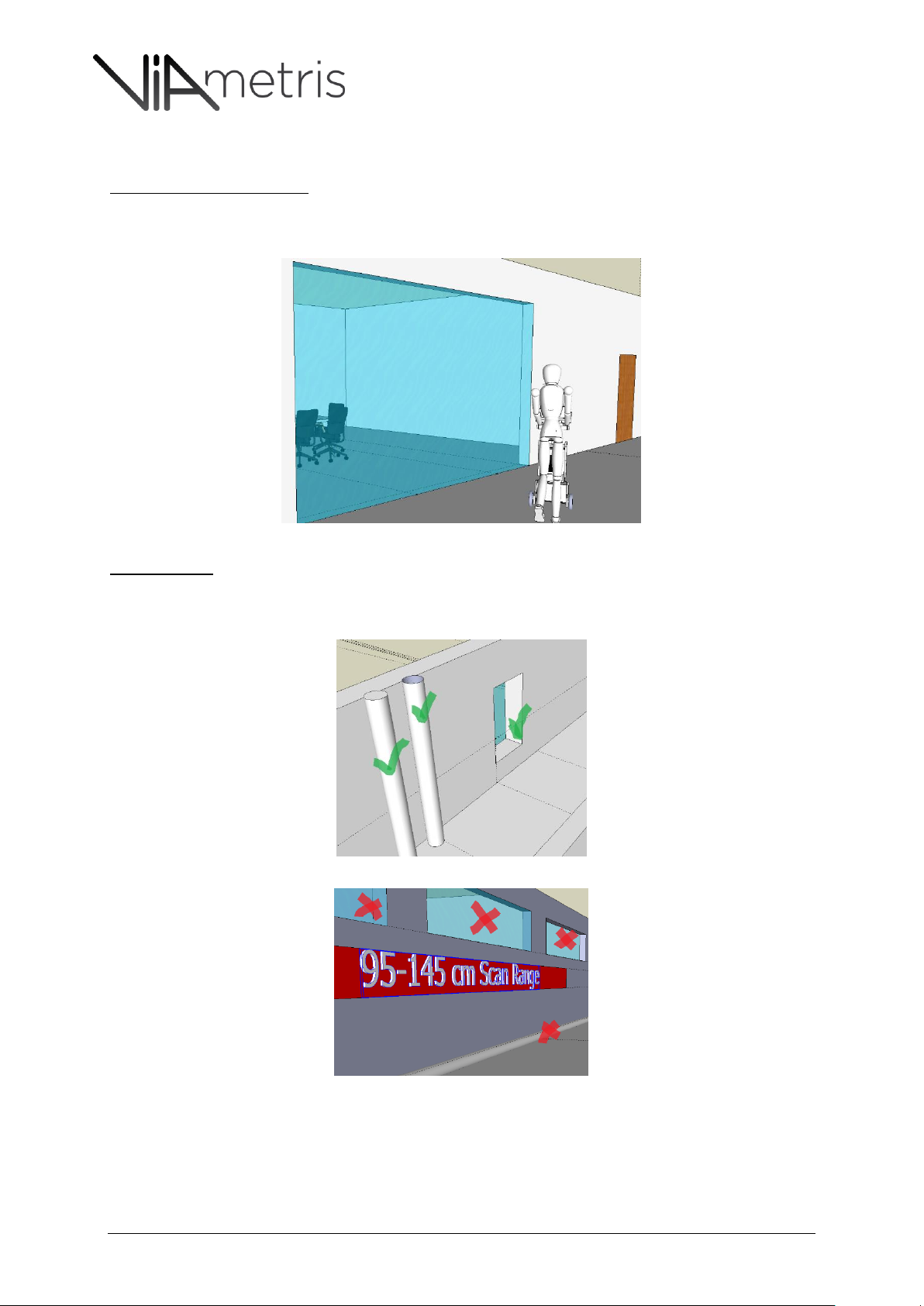
Internal Glass Partition Wall
Those partition walls have to be scanned like other partition walls, except that it remains mandatory
to scan the room on the other side of this partition, to avoid to create ghost rooms. See Figure 18.
Figure 18: Glass windows to be scanned like standard partition walls.
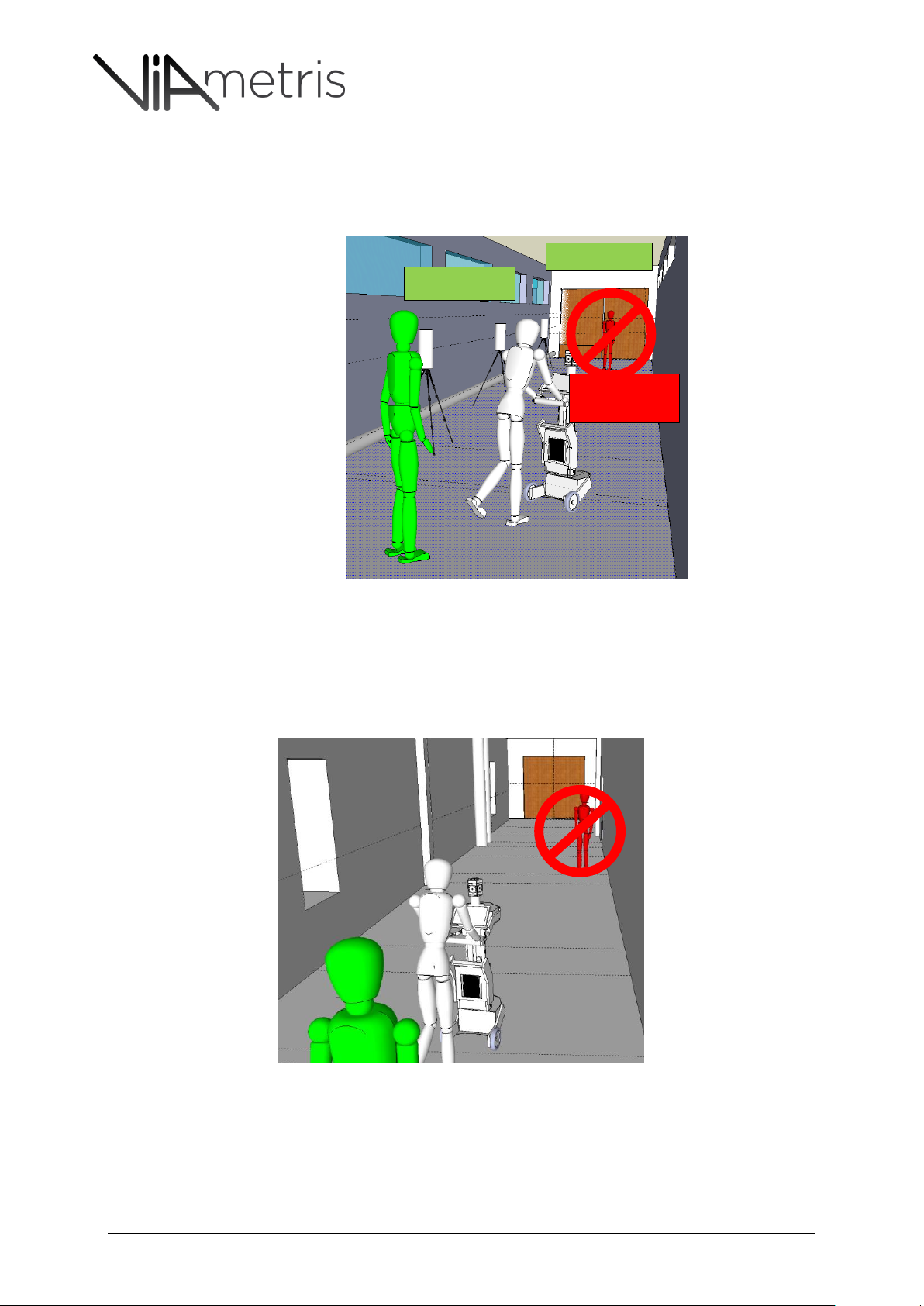
Long Corridors
Long corridors without any noticeable elements (no columns, no doors, no vertical heating
pipes, no high piece of furniture in the 95-145cm above the ground).see Figure 20 and Figure
21.
Figure 19: heating pipes and window are within range.
Figure 20: horizontal heating pipe and windows are out of the range.
o Such environment, without noticeable features within scan range, can lead to poor
measures if following precautions are not taken:
o Avoid scout to stand in front of the cart (behind the cart or out of radar range is
recommended)
iMS3D – Operating Guide Document v2.12 20
Page 21
iMS3D – Indoor Mobile Scanning System
Operating Guide. © Viametris SAS.
Scout not in
front of Cart
VM Targets
o If any door at the end of the corridor, ensure it is left closed.
o If required it is recommended to use Viametris Targets (see usage of Viametris Targets
in section 8.2.11). Alternatively other ad hock vertical elements can be used, as long
as they can be in the 95-145 cm vertical scan range. (i.e. coat stands…)
Figure 21: Long corridor without vertical noticeable elements equipped with Viametris Targets
In the other hand a long corridor with some noticeable elements (columns, doors, vertical
heating pipes, high pieces of furniture within the 95-145 cm vertical scan range) doesn’t
require special attentions. (apart from the usual precautions about the scout position Vs the
cart)See Figure 19 and Figure 22.
Figure 22: long corridor with noticeable elements: windows, heating pipe, column…within vertical scan range (95-145 cm) still
requires some basic precautions: close the doors at the end of the corridor and the scout has to remain out of the 270°
horizontal scan range.
iMS3D – Operating Guide Document v2.12 21
Page 22
iMS3D – Indoor Mobile Scanning System
Operating Guide. © Viametris SAS.
Mirrors:
Rooms or areas with mirrors on one side are not requiring special scanning handling but will
create ghost image that would require to be managed during post production.
Multiple mirrors can create artefacts that could be difficult to correct during post production,
it then recommended to “hide” facing mirrors if they can reflect on each other’s.
It is then recommended to first try and test system reaction when passing by mirrors. If
required hiding some mirrors (paper rolls…) can improve the scan.
8.2.4 DOORS: HOW TO HANDLE “OPEN/CLOSE”
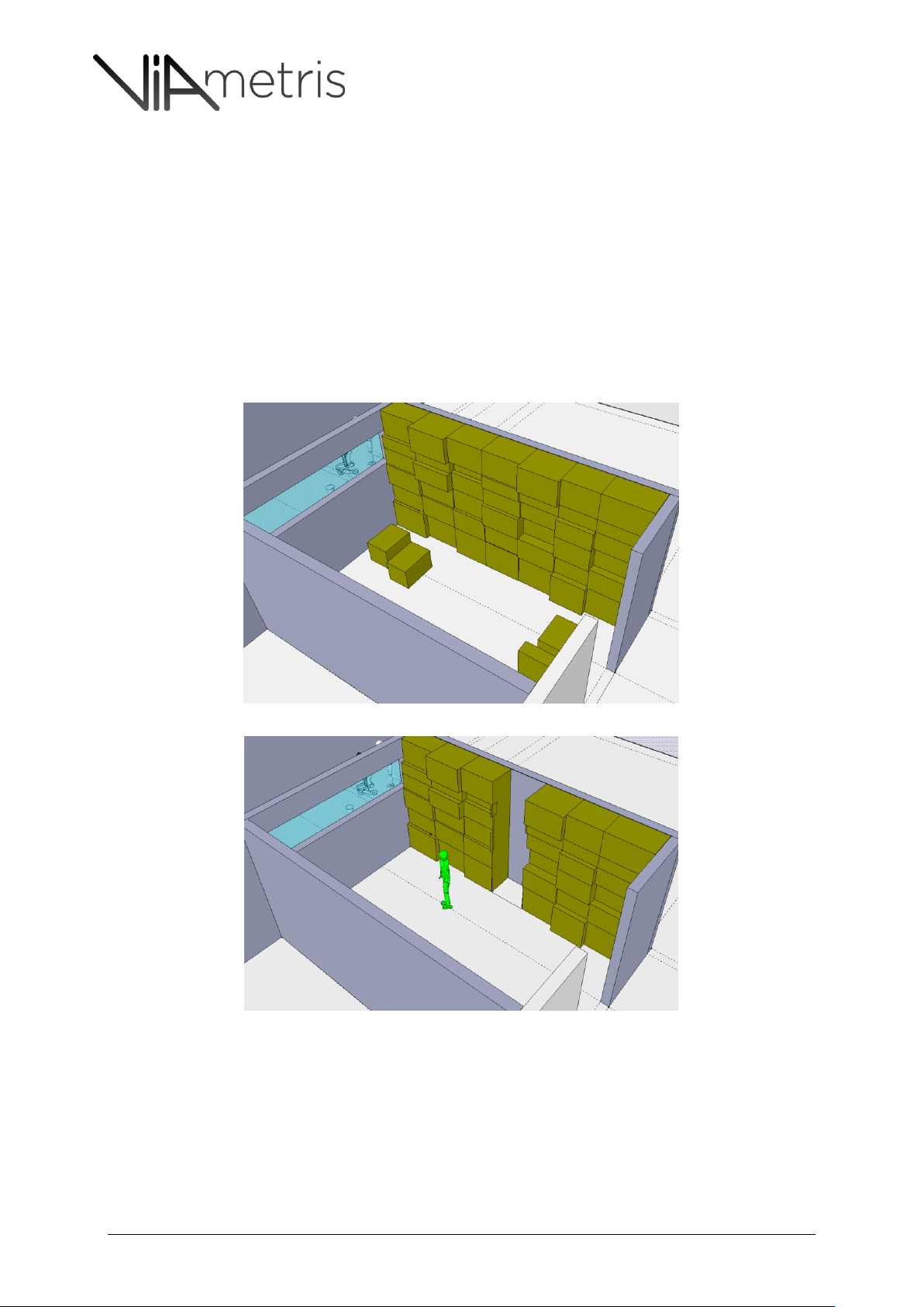
Doors separating areas and rooms have to be carefully handled during the scanning operation:
It is always recommended to slow down the scanning process while entering in a new room,
especially while stepping through the door step. See Figure 23.
Failure to do so could reduce the accuracy of the door step measurement which is always
considered as a very critical point.
Figure 23: to be sure to capture all critical door step details, it is recommended to slow down the walking pace while crossing
door steps
Opening of doors
If the cart operator is opening the door, it is recommended to follow the sequence:
o Operator approaches the door moving backward and handles the opening from his
back: Figure 24
o Operator slowly walk backward through the door step pulling the cart behind him
Figure 25
o Operator resumes normal scanning process pushing the cart in front of him
Figure 24 & Figure 25: Cart operator opening door
iMS3D – Operating Guide Document v2.12 22
Page 23
iMS3D – Indoor Mobile Scanning System
Operating Guide. © Viametris SAS.
Pictures 12a & 12b: Cart operator opening door
If the scout is opening the door, he has to do it without being in the radar range. If the scout
being in the radar range cannot be avoided, the scout has to remain still while the cart passes
by.
8.2.5 HOW TO HANDLE BUSY ROOMS (FURNITURE/STORAGE)
Busy shelves:
Carton box up to the ceiling can hide the separation wall and brings flaws in the room map.
Recommendation: Scoot to identify those areas and place shelves content in such a way that the cart
can access to the area and that the wall is visible enough from scanning device.
Figure 26: carton boxes hiding the wall and carton boxes on the cart’s way
Figure 27: wall has been made visible and the scout has cleaned up the way for the cart
8.2.6 RAMP UP/DOWN
There are strict rules to define standards ramp up & down in public buildings.
The most common ones are
o Not more than 5% slope/inclination overall.
o Not more than 8% on maximum 2 meters.
o Not more than 10% on maximum 0,5 meters.
iMS3D – Operating Guide Document v2.12 23
Page 24
iMS3D – Indoor Mobile Scanning System
Operating Guide. © Viametris SAS.
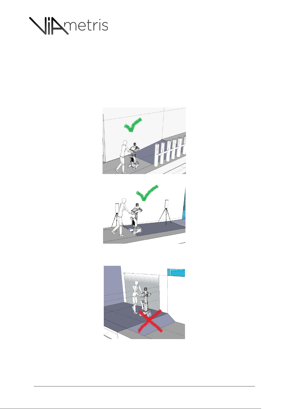
It is possible to operate scanning under those conditions but some precautions have to be taken.
Ensure proper usage of vertical objects at scanning range (95-145 cm above floor). See Figure
28.
Follow carefully the direction arrow on the scanning tablet (has to remain stable and straight).
If slopes are above the standards, it is not safe to drive the cart on such slopes (see section 10
about Safety).See Figure 30.
If there are no vertical references within vertical scan range (95-145cm) while driving the cart
in the ramp, it is recommended to use Viametris targets positioned in the ramp. See Figure 28.
Figure 28: Ramp is within standards and there are vertical objects within vertical scan range (95-145 cm)
Figure 29: Ramp is within standards but the trajectory lacks of vertical references within scan range (95-145cm) hence the
VM target usage is recommended.
Figure 30: Ramp slope is out of standard: safety cannot be guaranteed.
iMS3D – Operating Guide Document v2.12 24
Page 25
iMS3D – Indoor Mobile Scanning System
Operating Guide. © Viametris SAS.
8.2.7 HOW TO MOVE THE CART AND TRAJECTORY.
On top of other recommendations set above, it is important to have a clean and productive trajectory
to get an optimum measure.
Optimize radius of curvature (larger is better)
Regular speed: walking pace (slowing down for door steps)
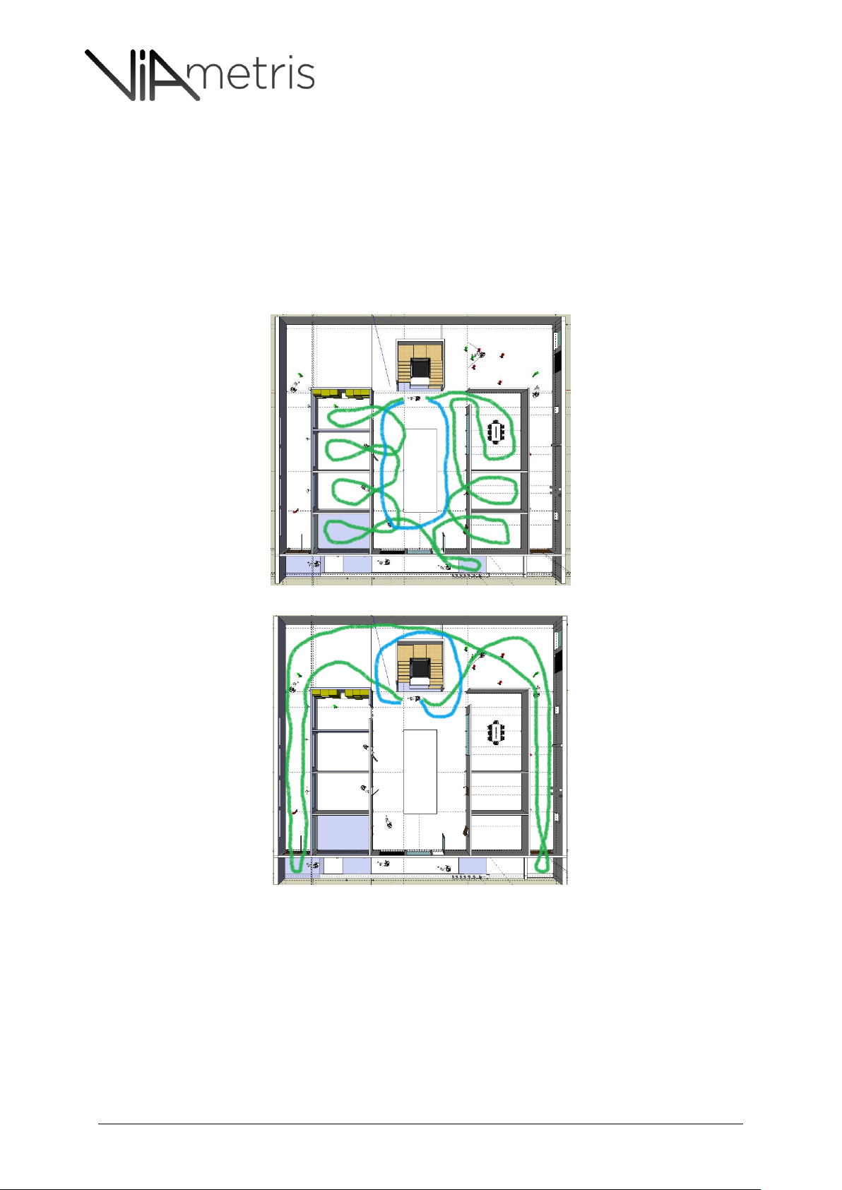
Ensure all rooms are scanned (see Figures 31 & 32 on how to have a large radius when moving
into offices.)
Close the loop by having an additional tour on the floor once the detailed tour is performed
Figure 31: Detailed rounds in Green & the “Close Loop” round in Blue
Figure 32: Detailed rounds in Green & the “Close Loop” round in Blue
8.2.8 TRAFFIC ON THE FLOOR.
Site staff & visitors can still navigate as normally without interfering with the measurement.
In case there is a scout, same recommendation applies in case of navigating across a crowd
(Shopping mall, lobby reception desk…) the scout should not remain in front of the cart (with
270° degree range) as his position could interfere with measurement.
iMS3D – Operating Guide Document v2.12 25
Page 26
iMS3D – Indoor Mobile Scanning System
Operating Guide. © Viametris SAS.
8.2.9 STAIRWAYS RELATED RECOMMENDATIONS
It is not possible to use stairways as the cart only operate on flat floors, but stairways should
not be forgotten while scanning a floor.
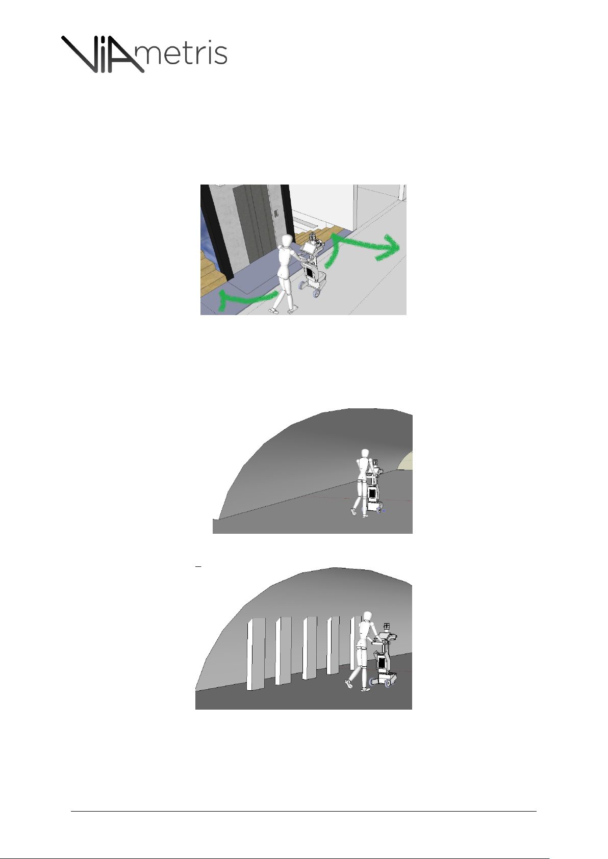
Bring the cart till the limit of the floor so most of the stairways can be scanned. The not visible
part of the stair way will not be scanned. See Figure 33
Figure 33: stairways have to be scanned but the cart CANNOT use stairways to go up & down.
8.2.10 CELLARS AND MANSARD ROOFED ATTICS:
iMS3D cannot operate if walls are not vertical and if there is no vertical objects within scan
range, therefore mansard roofed attics and heavily vaulted ceilings cellars cannot be scanned
without preparations and specific post treatment.
Figure 34: Vaulted ceilings without any vertical references within scan range (95-145 cm) requires specific precautions (VM
targets…)
Figure 35: Vaulted ceilings with vertical object within scan range (95-145cm) can be scanned.
iMS3D – Operating Guide Document v2.12 26
Page 27
iMS3D – Indoor Mobile Scanning System
Operating Guide. © Viametris SAS.
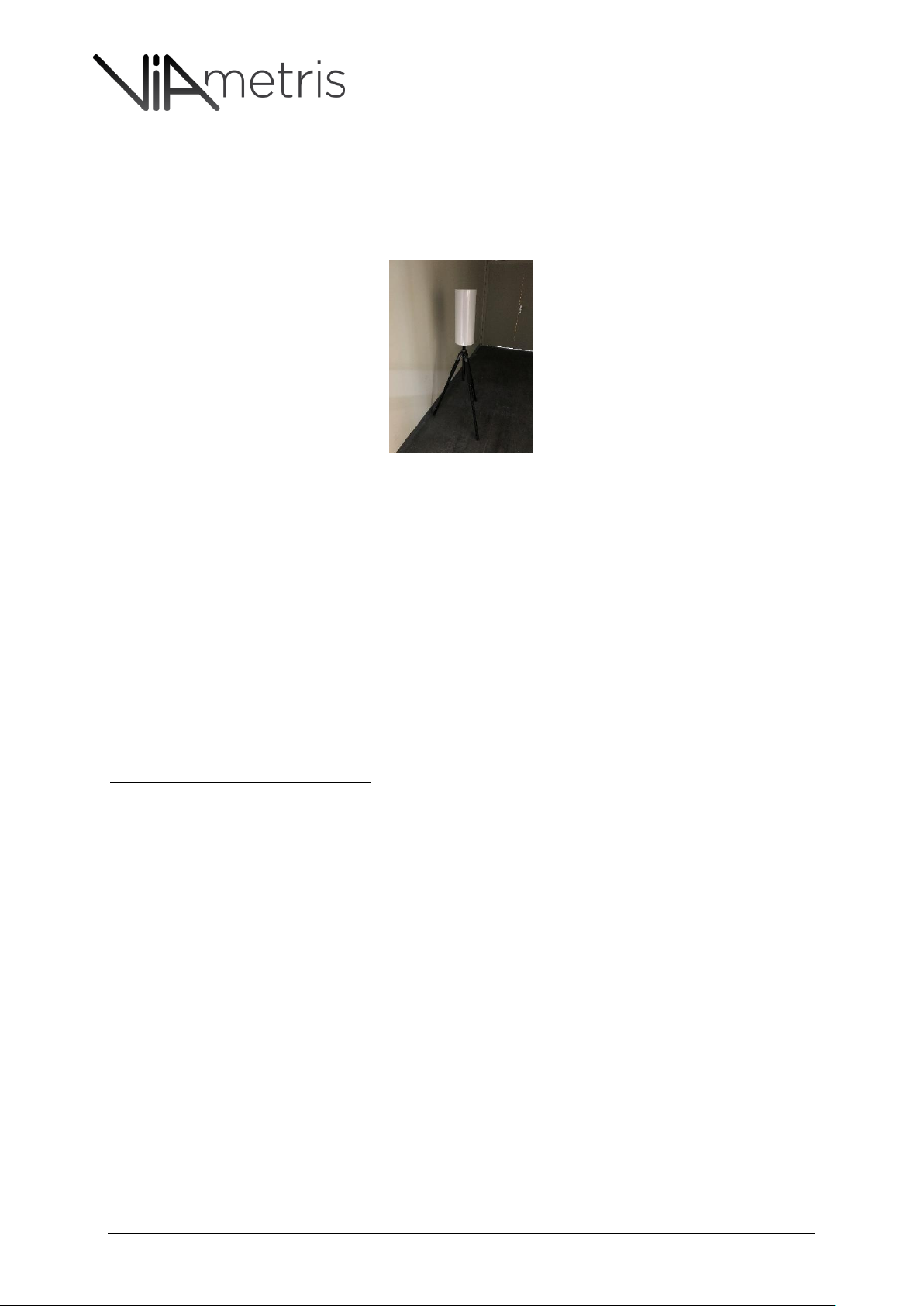
8.2.11 USAGE OF VIAMETRIS TARGETS
Viametris Targets usage is recommended when lacking of vertical references within scanning range
(95-145cm) (long corridor as described in Figure 21, very large empty spaces, ramps…).
It is recommended to place them every five meters, exact positioning is not critical.
If the scout is placing them, recommendation about scout positioning applies.
Figure 36: Viametris target
8.2.12 USAGE OF PAUSE VS STOP (WHEN TO DO, PRECAUTIONS TO TAKE)
When facing the need to interrupt the scan operations, what is preferable: to use Pause or Stop on the
control tablet?
Which precautions are to be undertaken when interrupting and starting again?
Interruptions can be caused by risk of interferences such as:
Person or group of persons that will be in the lidar range hence generating noises
Doors which require to be open
Light to be switch on…
See other chapters of this Operational Guide to see which occasions can request to interrupt
the scan operations.
In general it is better to select pause, if stop is selected then the 2 output projects will require to be
aligned during post production (ie in PPiMMs).
When pausing, as much as possible remain still and ensure the cart does not move from the position
it has when pausing. It makes the scanning process easy to interpret from a post-production
perspective.
If the cart has to be moved, it can be for 1 or 2 meters (the system should be able to reconstruct the
environment if it remains in the same area -same room).
It is recommended that when pausing the operator notes down that at which time (hh:mm) a pause
was required so that Post Production Operator would interpret the changes properly.
iMS3D – Operating Guide Document v2.12 27
Page 28
iMS3D – Indoor Mobile Scanning System
Operating Guide. © Viametris SAS.
9 SAFETY RECOMMENDATIONS:
Usage of the iMS3D is strictly aimed at indoor operations, balcony and terraces can be included
in the scanning process if they follow the basic safety and operational recommendations
(humidity, ramp slopes…)
It is not safe to add any other devices or objects on the cart. (Connected, attached…)
It is not safe to operate the iMS3D on slopes out of the standards indicated is Section 8.2.6.
It is not safe to operate in humid environment (i.e. moisture generated by construction, liquid
spilled on the floor) as the overall system is not waterproof.
It is not safe to operate in dusty environment.
It is not safe to stand or climb on the cart.
All other standard Safety recommendations apply to the usage of the iMS3D system.
Cart’s wheels are equipped with inflatable tires which requires standard usage precautions.
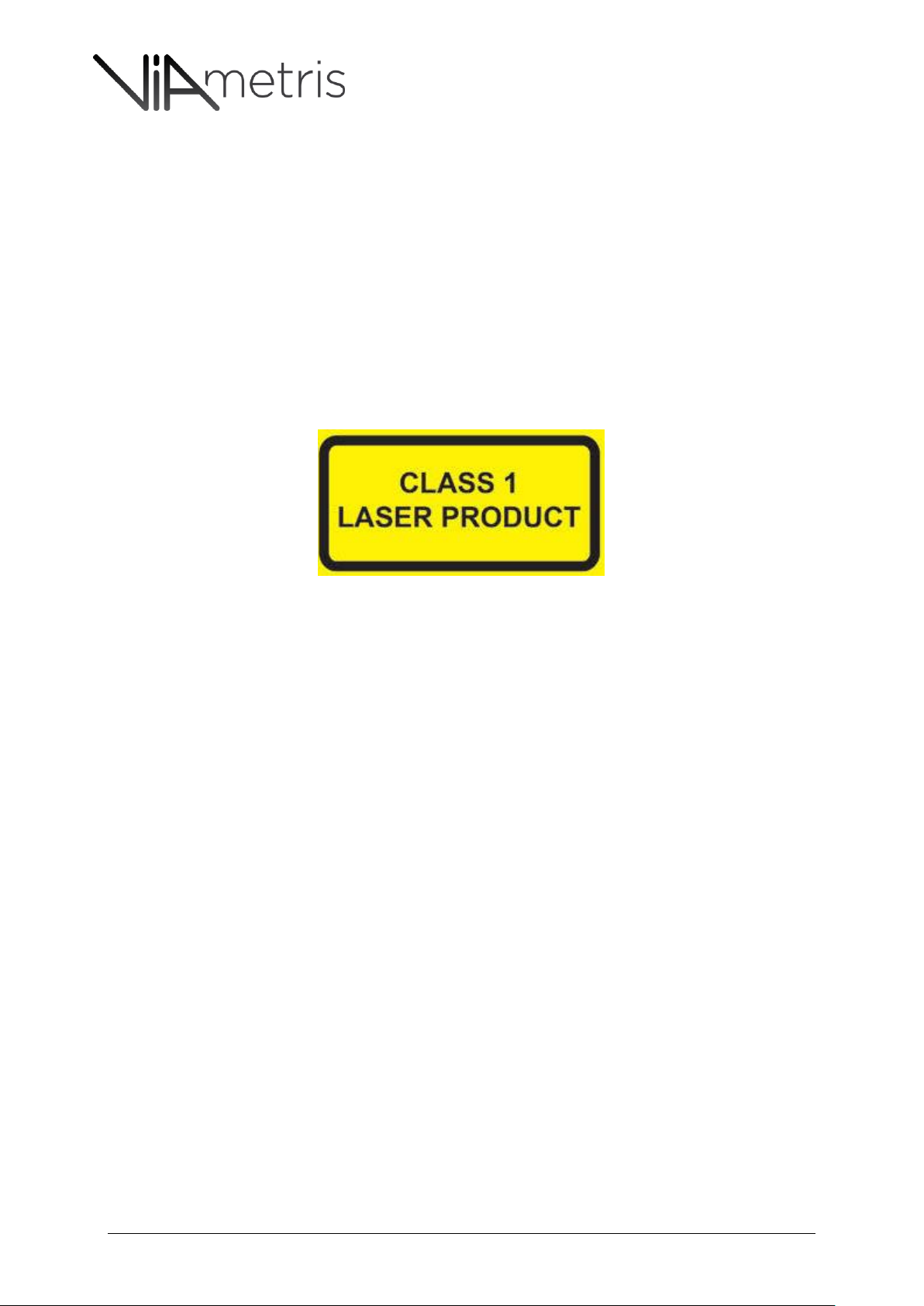
About the Laser Class 1 safety standard :
o Laser safety is guaranteed under normal use (operations which can be foreseen
rationally).
o Additional measures are not necessary to maintain the laser safety.
o Avoid looking at laser beam directly.
10 TRADEMARKS
- Hokuyo® is a trademark of HOKUYO AUTOMATIC CO., LTD.
- Ladybug® is a trademark of Point Grey Research, Inc.
iMS3D – Operating Guide Document v2.12 28
Page 29
iMS3D – Indoor Mobile Scanning System
Operating Guide. © Viametris SAS.
Scan Date Project
Operator Scout
Check
Check hour of operation
Check if blinders/curtains are internal or external
Identify “dark rooms”
Identify “highl y exposed” rooms
Identify major light changes situation
With eleme nts that can be used as objects Brief Scout (not in the laser range)
Without eleme nts (prepare targets) Prepare Targets
Prepare rolls of paper and tape to hide them while scanning.
Locate
Close the loop
Keys, PIN locks or badges
Check%
Check if any mansard roof or vaulted ceilings
Not in the Laser Range/in front of the cart
In case "in the Laser Range": stand still!
Ramps: check %
Rooms access and availability
Attics and Cellars
Situation
Scout brief
Identify long corridors
Light exposure
Identify mirrors reflecting on each others.
Stairways
Floor maps: trajectory
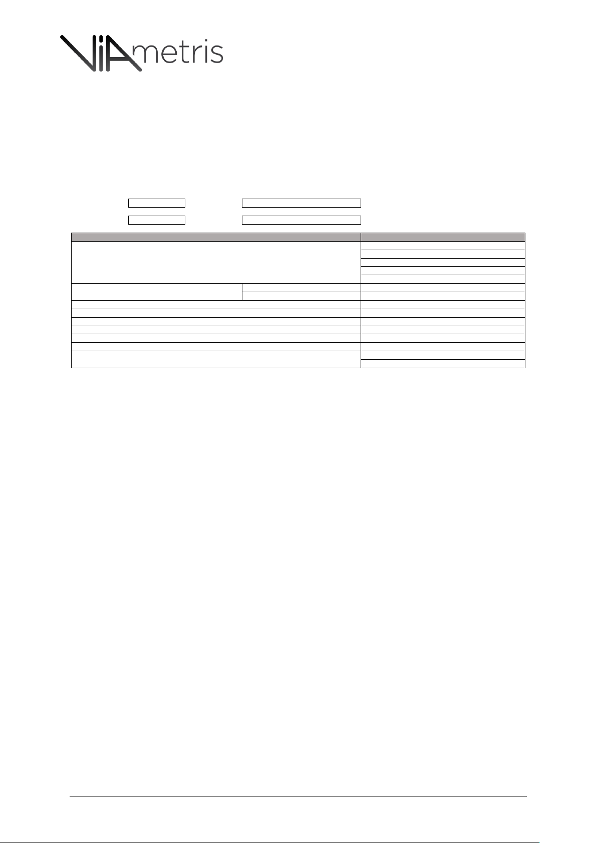
11 SITE CHECK LIST
Site check list (to prepare on/site)
It is recommended to have some of the points shared with the site owner to ensure smooth
scanning operations.
iMS3D – Operating Guide Document v2.12 29
Page 30
iMS3D – Indoor Mobile Scanning System
Operating Guide. © Viametris SAS.
#
Impact Severity
0=Low
2=High
Symptom Probable Cause Potential Fix
1 2
Inconsistent data captured in a
corridor
Lack of vertical object within vertical
range (95-145 cm)
Use VM Targets or alternatively any
object within the range (95-145 cm)
Get closer to walls and objects to scan
when under direct intense sun light
Alternatively close external blinds to
reduce light intensity ( note that
usage of internal blinds is not
recommended as they hide the
window structure details)
too long range (over 10m)
Reduce distance with objects to be
scaned
Uneven floors (gravels, cables on the
floor)
Prepare trajectory considering
unvenen areas.
3 2
Inconsistent data or ghosts captured
in some areas
Scout walking in front of the cart or
by the cart side
Respect the 270° scaning range and
remain behing the scan operator
(within the 90° behind the cart)
4 2
Poor data captured at door steps
Not enough data captured when
crossing doorsteps
Slowdown scanning pace while
crossing doorsteps
5 1
Very dark pictures in some areas
Quick change of light made the image
capture very dark (as the camera has
preset aperture speed)
Take some pictures manually and
leave the camera adapts to different
light conditions.
6 1
Picture too bright/over exposure
Quick change of light made the image
capture too bright (as the camera has
preset aperture speed)
Take some pictures manually and
leave the camera adapts to different
light conditions.
Direct sun light impact radar range
2
1
Very noisy or poor signal captured in
some rooms
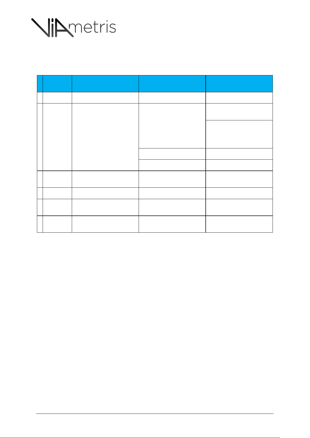
12 TROUBLESHOOTING
In general level of impact severity is lower for noise and ghost image while higher for inconsistent
trajectory which leads to wrong measures.
iMS3D – Operating Guide Document v2.12 30
Page 31

iMS3D – Indoor Mobile Scanning System
Operating Guide. © Viametris SAS.
13 TABLE OF FIGURES.
Figure 1: Roller frame .............................................................................................................................. 4
Figure 2: Mast Frame #1 .......................................................................................................................... 4
Figure 3: Mast frame #2 including the handle ........................................................................................ 4
Figure 4: Processing unit ......................................................................................................................... 4
Figure 5: Sensor unit ................................................................................................................................ 4
Figure 6: Rugged Tablet & charger .......................................................................................................... 4
Figure 7: System Charger......................................................................................................................... 5
Figure 8: Embedded Tablet charger: this one should be used when scanning ....................................... 5
Figure 9: MOLEX connector to activate the battery ................................................................................ 5
Figure 10: XLR connector used for chargers to be connected to the processing unit ............................ 5
Figure 11:overall recommendations for some real life situations. ....................................................... 17
Figure 12:the scout has to remain out of the front scan range (270°),................................................. 18
Figure 13: the scout has to remain out of the front scan range (270°). Red is wrong, green is OK ...... 18
Figure 14: external blinds have to be closed down as they don’t hide important details. ................... 18
Figure 15: internal blinds have to be left open as they hide important details. ................................... 19
Figure 16: moving to an intense sun light area requires a pause and manual picture shootings ........ 19
Figure 17: The user can force shooting by clicking the camera status light ......................................... 19
Figure 18: Glass windows to be scanned like standard partition walls. ................................................ 20
Figure 19: heating pipes and window are within range. ....................................................................... 20
Figure 20: horizontal heating pipe and windows are out of the range. ................................................ 20
Figure 21: Long corridor without vertical noticeable elements equipped with Viametris Targets ...... 21
Figure 22: long corridor with noticeable elements ............................................................................... 21
Figure 23: to be sure to capture all critical door step details, it is recommended to slow down......... 22
Figure 24 & Figure 25: Cart operator opening door .............................................................................. 22
Figure 26: carton boxes hiding the wall and carton boxes on the cart’s way ....................................... 23
Figure 27: wall has been made visible and the scout has cleaned up the way for the cart .................. 23
Figure 28: Ramp is within standards and there are vertical objects within vertical scan range .......... 24
Figure 29: Ramp is within standards but the trajectory lacks of vertical references ............................ 24
Figure 30: Ramp slope is out of standard: safety cannot be guaranteed. ............................................ 24
Figure 31: Detailed rounds in Green & the “Close Loop” round in Blue ............................................... 25
Figure 32: Detailed rounds in Green & the “Close Loop” round in Blue ............................................... 25
Figure 33: stairways have to be scanned but the cart CANNOT use stairways to go up & down. ........ 26
Figure 34: Vaulted ceilings without any vertical references ................................................................. 26
Figure 35: Vaulted ceilings with vertical object within scan range (95-145cm) can be scanned. ......... 26
Figure 36: Viametris target .................................................................................................................... 27
iMS3D – Operating Guide Document v2.12 31
Page 32

iMS3D – Indoor Mobile Scanning System
Operating Guide. © Viametris SAS.
How to contact Viametris
Contact Viametris when you have questions about using and operating our products:
Email : [email protected]
Phone +33 243 497 791 (opening hours 09 :00-18 :00-CEST-UTC+2- Mo-Fr)
Support can be delivered in English and French.
To get the best support, please ensure you have ready the versions of the products used and
the exact circumstances you experienced an issue with.
Screenshots and pictures are also be used to back up questions via email.
iMS3D – Operating Guide Document v2.12 32
 Loading...