

VIA Mainboard VB8003 User Manual

user manual
VB8003
Mini-ITX Mainboard
Revision
1.02

II
Copyright and Trademarks
Copyright © 2010-2012 VIA Technologies Incorporated. All rights reserved.
No part of this document may be reproduced, transmitted, transcribed, stored in a
retrieval system, or translated into any language, in any form or by any means, electronic,
mechanical, magnetic, optical, chemical, manual or otherwise without the prior written
permission of VIA Technologies, Incorporated.
All trademarks are the property of their respective holders.
PS/2 is a registered trademark of IBM Corporation.
Disclaimer
No license is granted, implied or otherwise, under any patent or patent rights of VIA
Technologies. VIA Technologies makes no warranties, implied or otherwise, in regard to
this document and to the products described in this document. The information provided
in this document is believed to be accurate and reliable as of the publication date of this
document. However, VIA Technologies assumes no responsibility for the use or misuse of
the information in this document and for any patent infringements that may arise from the
use of this document. The information and product specifications within this document are
subject to change at any time, without notice and without obligation to notify any person
of such change.
Regulatory Compliance
FCC-B Radio Frequency Interference Statement
This equipment has been tested and found to comply with the limits for a class B digital
device, pursuant to part 15 of the FCC rules. These limits are designed to provide
reasonable protection against harmful interference when the equipment is operated in a
commercial environment. This equipment generates, uses, and can radiate radio
frequency energy and, if not installed and used in accordance with the instruction manual,
may cause harmful interference to radio communications. Operation of this equipment in a
residential area is likely to cause harmful interference, in which case the user will be
required to correct the interference at his personal expense.
Notice 1
The changes or modifications not expressly approved by the party responsible for
compliance could void the user's authority to operate the equipment.
Notice 2
Shielded interface cables and A.C. power cord, if any, must be used in order to comply
with the emission limits.
Battery Recycling and Disposal
Only use the appropriate battery specified for this product.
Do not re-use, recharge, or reheat an old battery.
Do not attempt to force open the battery.
Do not discard used batteries with regular trash.
Discard used batteries according to local regulations.
Tested To Comply
With FCC Standards
FOR HOME OR OFFICE USE

III
Safety Precautions
Do’s
o Always read the safety instructions carefully.
o Keep this User's Manual for future reference.
o All cautions and warnings on the equipment should be
noted.
o Keep this equipment away from humidity.
o Lay this equipment on a reliable flat surface before setting
it up.
o Make sure the voltage of the power source and adjust
properly 110/220V before connecting the equipment to the
power inlet.
o Place the power cord in such a way that people cannot
step on it.
o Always unplug the power cord before inserting any add-on
card or module.
o If any of the following situations arises, get the equipment
checked by authorized service personnel:
o The power cord or plug is damaged.
o Liquid has penetrated into the equipment.
o The equipment has been exposed to moisture.
o The equipment has not worked well or you cannot
get it work according to User's Manual.
o The equipment has dropped and damaged.
o The equipment has obvious sign of breakage.
Don’ts
o Do not leave this equipment in an environment
unconditioned or in a storage temperature above 60°C
(140°F). The equipment may be damaged.
o Do not leave this equipment in direct sunlight.
o Never pour any liquid into the opening. Liquid can cause
damage or electrical shock.
o Do not place anything over the power cord.
o Do not cover the ventilation holes. The openings on the
enclosure protect the equipment from overheating

IV
Box Contents
VB8003 Mini-ITX mainboard
SATA cable
I/O bracket
Driver utility CD
Screw pack for DVI port

V
T
ABLE OF
C
ONTENTS
1 Product Overview...............................................................................................1
Key Components ................................................................................................. 2
VIA Nano 1.6 GHz NanoBGA2 Processor ........................................2
VIA VX800 Media System Processor..................................................... 2
S3 Graphics Chrome 435 ULP................................................................. 3
VIA VT1708 High Definition Audio Codec....................................... 3
VIA VT1211 Super I/O................................................................................. 3
Mainboard Specifications ................................................................................4
VB8003 Layout..................................................................................................... 6
Top Side .............................................................................................................. 6
Bottom Side.......................................................................................................7
VB8003 Back Panel Layout ............................................................................8
PS2 Keyboard ................................................................................................... 8
PS2 Mouse .........................................................................................................8
VGA port ............................................................................................................8
DVI port ..............................................................................................................8
COM port ...........................................................................................................8
HDMI® port ....................................................................................................... 8
Giga LAN port .................................................................................................9
USB port.............................................................................................................. 9
Stereo Right/Left jack.................................................................................... 9
2 Onboard Connectors, Slots and Pin Headers.....................................11
Top Side Connectors .......................................................................................12
CPU .....................................................................................................................12
CPU and SYS Fan: CPUFAN1 and SYSFAN1...................................13
S3 Graphics Fan connector: S3FAN1 ................................................15
ATX 20-Pin Power connector: ATX_POWER1...............................16
Serial ATA connectors: SATA1 and SATA2 ......................................17
IDE pin header: IDE1..................................................................................18
Video Capture Port: VCP1 .......................................................................19
LVDS INVERTER connector: INVERTER1 ..........................................21
LVDS Panel connector: LVDS1..............................................................22
SPDIF OUT connector: SPDIF.................................................................23
Memory Module Installation...................................................................24
Front Panel pin header: F_PANEL .......................................................27
Front Audio pin header: F_AUDIO ....................................................28

VI
USB pin header: USB_2.............................................................................29
KBMS/CIR pin header: KBMS ..................................................................30
Low Pin Count pin header: LPC ...........................................................31
Digital I/O pin header: DIO1..................................................................32
SPI pin header: SPI1.....................................................................................33
MFX pin header: MFX1 .............................................................................34
COM pin header: COM2..........................................................................35
FIR pin header: FIR1 ....................................................................................36
SMBus pin header: SMBus .......................................................................37
System Thermal Resister: J4 .....................................................................38
Bottom Side Connector..................................................................................39
CompactFlash connector CF1:..............................................................39
3 Onboard Jumpers ............................................................................................41
Clear CMOS: CLEAR_CMOS....................................................................42
COM2 5V/12V Select: J2 .........................................................................43
Power Select for LVDS Inverter and Panel Power: J3........................................44
IDE DOM Power Select: J5......................................................................45
SATA DOM Power Select: J6 ..................................................................46
CF Voltage and Master/Slave Select: CF_SEL.................................47
4 BIOS Setup............................................................................................................49
Entering the BIOS Setup Menu ..................................................................50
Control Keys .........................................................................................................50
Getting Help ........................................................................................................51
Main Menu ...........................................................................................................52
Standard CMOS Features.........................................................................52
Advanced BIOS Features .........................................................................52
Advanced Chipset Features....................................................................52
Integrated Peripherals................................................................................52
Power Management Setup.....................................................................52
PnP/PCI Configurations.............................................................................52
PC Health Status............................................................................................53
Frequency/Voltage Control....................................................................53
Load Optimized Defaults..........................................................................53
Set Supervisor Password ...........................................................................53
Set User Password .......................................................................................53
Save & Exit Setup ..........................................................................................53
Exit Without Saving.....................................................................................53
Standard CMOS Features..............................................................................54
Date ....................................................................................................................54
Time ....................................................................................................................54
Video..................................................................................................................54
Halt On..............................................................................................................54
IDE Drives..............................................................................................................55
IDE Channel 0 Master................................................................................55

VII
IDE Channel 0 Slave ...................................................................................55
IDE Channel 1 Master................................................................................56
IDE Channel 1 Slave ...................................................................................56
Advanced BIOS Features...............................................................................58
Virus Warning................................................................................................58
CPU L1 & L2 Cache.....................................................................................58
CPU L2 Cache ECC Checking................................................................58
Quick Power On Self-Test.........................................................................59
First/Second/Third Boot Device............................................................59
Boot Other Device.......................................................................................59
Boot Up NumLock Status.........................................................................59
Typematic Rate Setting ..............................................................................59
Typematic Rate (Chars/Sec) ....................................................................60
Typematic Delay (Msec)............................................................................60
Security Option..............................................................................................60
MPS Version Control for OS....................................................................60
OS Select for DRAM > 64MB ..................................................................60
HDD S.M.A.R.T. Capability ........................................................................60
Video BIOS Shadow ...................................................................................60
Full Screen Logo Show .............................................................................61
Summary Screen Show.............................................................................61
CPU Features.......................................................................................................62
Thermal Management...............................................................................62
Hard Disk Boot Priority....................................................................................63
Advanced Chipset Features .........................................................................64
Memory Hole .................................................................................................64
System BIOS Cacheable ............................................................................64
Video RAM Cacheable ..............................................................................64
GFX & PCIE VGA Co-Exist ........................................................................64
Internal VGA Control.......................................................................................65
VGA Share Memory Size ..........................................................................65
Direct Frame Buffer.....................................................................................65
Select Display Device..................................................................................65
Panel Type .......................................................................................................65
CPU & PCI Bus Control ...................................................................................66
PCI Master 0 WS Write ..............................................................................66
PCI Delay Transaction ................................................................................66
Integrated Peripherals.....................................................................................67
VIA Wireless LAN Support.......................................................................67
Onboard LAN Boot ROM ........................................................................67
VIA OnChip IDE Device .................................................................................68
CF Card ATA66 .............................................................................................68
SATA Controller.............................................................................................68
IDE DMA Transfer Access ........................................................................68

VIII
OnChip IDE Channel1 ..............................................................................68
IDE Prefetch Mode ......................................................................................68
Secondary Master PIO ...............................................................................68
Secondary Slave PIO...................................................................................68
Secondary Master UDMA ........................................................................69
Secondary Slave UDMA............................................................................69
IDE HDD Block Mode ................................................................................69
VIA OnChip PCI Device..................................................................................70
Azalia HDA Controller................................................................................70
Super IO Device .................................................................................................71
Onboard Serial Port 1 ................................................................................71
Onboard Serial Port 2 ................................................................................71
Onboard Fast IR............................................................................................71
Fast IR IRQ ........................................................................................................71
Fast IR DMA.....................................................................................................71
Internal Serial Port 3 ....................................................................................72
Internal Serial Port 4 ....................................................................................72
Internal IrDA Controller.............................................................................72
USB Device Setting ...........................................................................................73
USB 1.0 Controller .......................................................................................73
USB 2.0 Controller .......................................................................................73
USB Operation Mode ................................................................................73
USB Keyboard Function............................................................................73
USB Mouse Function .................................................................................74
USB Storage Function................................................................................74
Power Management Setup..........................................................................75
ACPI Suspend Type .....................................................................................75
Power Management Option..................................................................75
HDD Power Down .....................................................................................75
Suspend Mode ..............................................................................................76
Video Off Option..........................................................................................76
Video Off Method........................................................................................76
MODEM Use IRQ .........................................................................................76
Soft-Off by PWRBTN....................................................................................76
Run VGABIOS if S3 Resume....................................................................76
AC Loss Auto Restart ..................................................................................77
WatchDog Run/Stop .................................................................................77
WatchDog Count Value ..........................................................................77
Wakeup Event Detect.....................................................................................78
PS2KB Wakeup Select ................................................................................78
PS2KB Wakeup Key Select .......................................................................78
PS2MS Wakeup Key Select ......................................................................78
PS2 Keyboard Power On..........................................................................78
PS2 Mouse Power On................................................................................79

IX
RTC Alarm Resume ......................................................................................79
Date (of Month)............................................................................................79
Resume Time (hh : mm : ss) ....................................................................79
PnP/PCI Configuration....................................................................................80
Init Display First..............................................................................................80
PNP OS Installed ...........................................................................................80
Reset Configuration Data.........................................................................80
Resources Controlled By...........................................................................81
PCI/VGA Palette Snoop ............................................................................81
Assign IRQ for VGA.....................................................................................81
Assign IRQ for USB ......................................................................................81
Maximum Payload Size..............................................................................81
PC Health Status.................................................................................................82
Frequency/Voltage Control.........................................................................83
DRAM Frequency ........................................................................................83
DRAM Channel Mode ...............................................................................83
DRAM CAS Latency Control ...................................................................83
DRAM Burst Length....................................................................................83
DDR 1T Command Rate ...........................................................................83
DRDY Table .....................................................................................................83
ODT.....................................................................................................................83
Spread Spectrum..........................................................................................84
CPU clock .........................................................................................................84
Load Optimized Defaults...............................................................................85
Set Supervisor/User Password ....................................................................86
Save & Exit Setup ...............................................................................................87
Exit Without Saving ..........................................................................................88
5 Driver Installation...............................................................................................89
Driver Utilities.......................................................................................................90
Getting Started ..............................................................................................90
Running the Driver Utilities CD .............................................................90
CD Content ..........................................................................................................91

1
1
Product Overview

2
The ultra-compact and highly integrated VIA VB8003 uses the
Mini-ITX mainboard form-factor developed by VIA Technologies,
Inc. The mainboard enables the creation of an exciting new
generation of small, ergonomic, innovative and affordable
embedded systems. Through a high level of integration, the MiniITX mainboard is only 66% of the size of FlexATX mainboard form
factor. The mainboard comes with a VIA Nano 1.6 GHz
NanoBGA2 processor.
KEY COMPONENTS
VIA Nano 1.6 GHz NanoBGA2 Processor
The VIA Nano is a 64-bit superscalar processor in x86 platform
using a 65 nanometer process technology. It delivers an energyefficient, powerful performance, with cool and quiet operation all
within an ultra compact NanoBGA2 package measuring 21mm x
21mm. Perfectly fit for embedded system applications such as
industrial PCs, test machines, measuring equipment, digital
signage, medical PCs, monitoring systems, gaming machines, invehicle entertainment, and etc. The VIA Nano also boasts of
immersive multimedia performance, connectivity and computing
applications. When combined with the all-in-one highly integrated
digital media VX800 IGP chipset, system developers can utilize an
impressive range of features for a wide range of notebook and
desktop applications.
VIA VX800 Media System Processor
The VIA VX800 all-in-one digital media IGP chipset integrates a
premium graphics engine, HD audio controller, DDR2 memory
controller, 800MHz FSB processor interface, and extensive I/O
capabilities in a single chip design. The VIA VX800 is based on a
highly sophisticated power efficient architecture that enables such
rich integration into a compact package with a maximum power
envelope of just 5 W.

3
S3 Graphics Chrome 435 ULP
The S3 Graphics Chrome 435 ULP (Ultra Low Power) graphics
processor offers superb performance-per-watt metrics, boasting
incredibly low power draw. The S3 Graphics Chrome 435 ULP
offers users an immersive visual experience without sacrificing
battery life and its support for DirectX 10.1 allows realistic 3D
rendering and increased visual acuity through improved Antialiasing (AA) and Image/ Texture, higher precision formats, and
programmable lightning effects.
The S3 435 ULP also has the latest ChromotionHD Video Engine
that enables acceleration for all leading video standards. It also has
the sophisticated S3 Graphics PowerWise Technology algorithms
that manage the power usage of the GPU — delivering optimal
balance between performance and power on-the-fly. The S3
Graphics PowerWise Technology brings together graphics
performance and power efficiency for embedded systems.
VIA VT1708 High Definition Audio Codec
The VIA VT1708 delivers top quality audio performance —
supporting the latest 8-channel, 24-bit, 192 kHz audio content for
an all-round high-fidelity experience. Integrating stereo DACs with
a 100 dB signal-to-noise ratio, the VIA VT1708 includes features
such as a high quality headphone amplifier, enhanced recording
support, and advanced power management.
VIA VT1211 Super I/O
The VIA VT1211 is a full function Super I/O chip with a floppy disk
controller, an IEEE-1284 parallel port interface, two 16C550-UARTbased serial port interfaces, a VFIR (Very Fast IR) controller, a game
port that supports two joysticks, a MIDI interface, and a 4 MB
Flash-ROM interface.
Its integrated hardware monitor controller controls the speed of
up to two fans, monitors two fan tachometers, and five universal
analog inputs for measuring voltage or temperature. The VT1211
is ACPI ready with a hardware monitor engine built-in to monitor
system health.

4
MAINBOARD SPECIFICATIONS
CPU
VIA Nano 1.6 GHz NanoBGA2 processor with fansink
• NanoBGA2 package
• 800 MHz Front Side Bus
Chipset
VIA VX800 Advanced All-in-One System Processor
Graphics
S3 Chrome 435 ULP through PCIe x4 with GDDR3
256MB 32x32x2
VIA Chrome9 HC integrated graphics with 3D/2D and
unified video decoding accelerator
Supports up to 4 displays
Note: VB8003 default init display priority is S3G 435ULP
(PCIE) with DVI as default display output. To
change init display priority to VX800 (onboard),
please refer to BIOS menu page 80.
System Memory
Two DDR2 533/667 SODIMM slot
• Up to 4 GB memory size
Storage Expansion
One UltraDMA 133/100/66/33 44-pin IDE connector
Two SATA 3Gb/s connector
One CF Type II
Audio
VIA VT1708B High Definition Audio Codec
LAN
Two VIA VT6130 Gigabit Ethernet controller
Super I/O
VIA VT1211 LPC Super I/O
Onboard I/O
Connectors
One USB pin connector for two additional USB 2.0 ports
• supports VIA VT6656 WLAN module
One Serial port pin connector for COM2 (5V/12V)
Two Serial ports reserved through video capture slot (5V/12V)
• add-on card required
One PS2 mouse/keyboard pin connector
One DIO pin connector
• 4 GPI
• 4 GPO
One LPC pin connector
One FIR pin connector (IRDA 1.0)
One SMBus connector
One Front-panel pin connector
One Front audio pin connector (MIC and Line-out)
One SPDIF pin connector
One Digital video input for CCIR-656/601/transport stream video
One MFX pin connector
One Backlight control connector (controls inverter power
and panel brightness)
One 24-bit 2-channel LVDS connector
One fan pin connector for S3 Graphics 435 ULP fan
Two fan pin connectors for CPU and System fans
One system temperature reading connector
One ATX power connector
5
Back Panel I/O Ports
One PS2 mouse port
One PS2 keyboard port
Two HDMI® ports
One DVI-I (default display) connector
Two RJ45 ports
One serial port
One VGA port
Four USB 2.0 ports
Two RCA jacks
System Monitoring
and Management
Wake-On-LAN
Keyboard Power-on
Timer-Power-on
CPU/System Voltage Monitoring
System Temperature Monitoring
Fan speed monitoring
WatchDog Timer
AC power failure recovery
BIOS
Award BIOS
SPI 4/8Mbit LPC flash memory
Operating System
Windows XP, XPe and Linux
Operating
Temperature
0°C up to 60°C
Operating
Humidity
0% ~ 95% (relative humidity; non-condensing)
Form Factor
Mini-ITX
17cm x 17cm
Note:
System resources (such as BIOS, PCI, etc.) require physical
memory address locations that reduce available memory
addresses above 3 GB. This may result in less than 4 GB of
memory being available to the operating system and
applications.
With certain limitations, DVI-I (default display) can support DVI-D + CRT using a Y-cable
1. CRT will always show the same content with the primary display device from the S3G 435ULP.
2. CRT may not display correctly due to the timing limitation. Users may need to choose a specific CRT panel if
this function is desired.
6
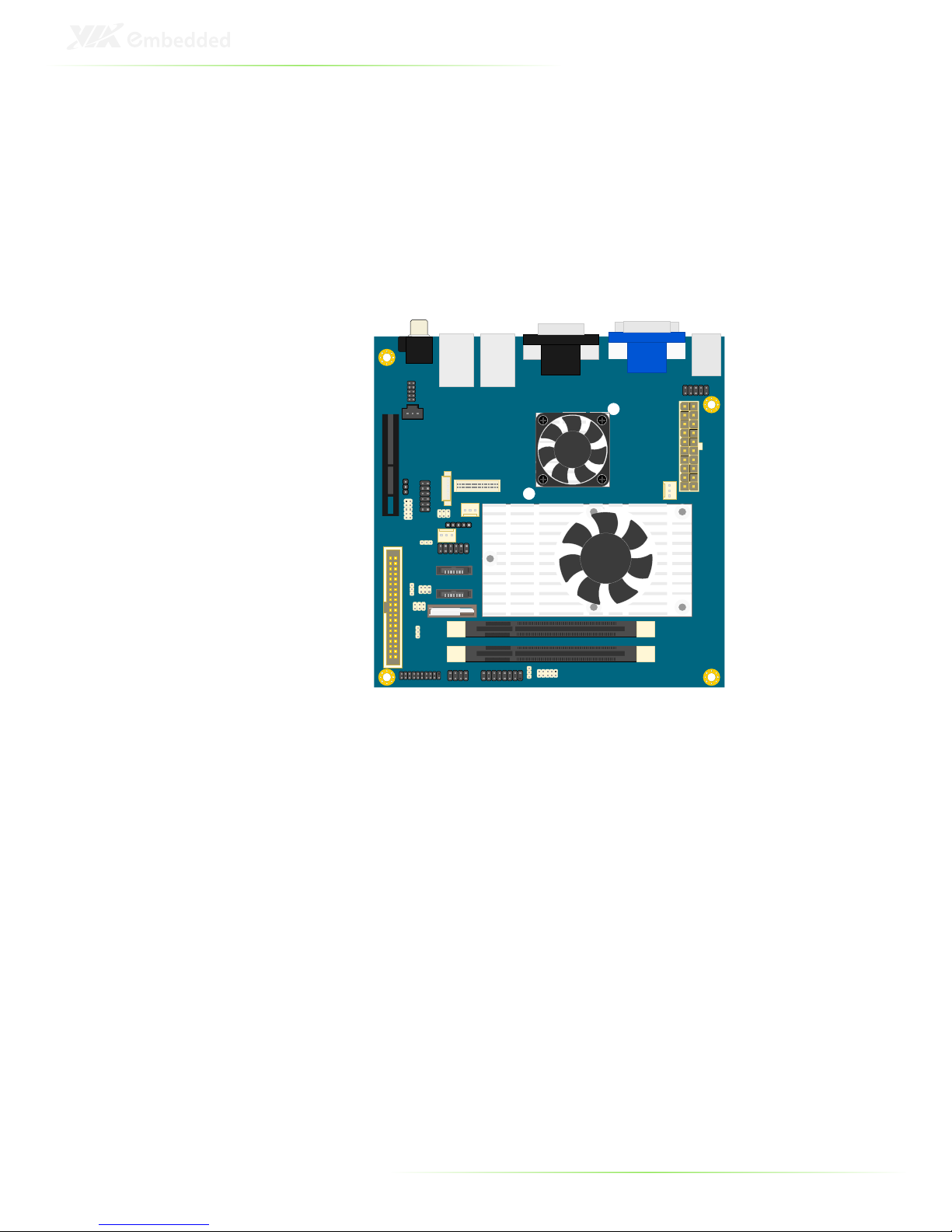
VB8003 LAYOUT
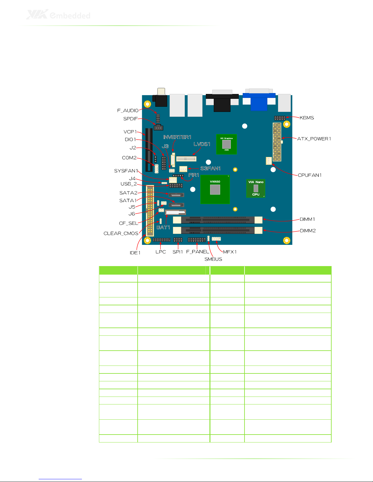
Top Side
Symbol
SymbolSymbol
Symbol Description
DescriptionDescription
Description Symbol
SymbolSymbol
Symbol Description
DescriptionDescription
Description
F_AUDIO Front Audio pin header
LPC Low Pin Count pin header
SPDIF Sony/Philips Digital
Interconnect Format
SPI1 SPI pin header
VCP1 Video Capture Port F_PANEL Front Panel pin header
DIO1 Digital I/O pin header SMBUS SMBus pin header
J2 COM2 5V/12V voltage
selector
MFX1 MFX pin header
COM2 COM port pin header KBMS Keyboard and Mouse pin header
SYSFAN1 System Fan connector ATX_
POWER
ATX power connector
J4 System Thermal Resister
connector
CPUFAN1 CPU fan
USB_2 USB pin header DIMM1 SODIMM slot 1
SATA1 SATA port 1 DIMM2 SODIMM slot 2
SATA2 SATA port 2 INVERTER1 LVDS Inverter connector
J5 IDE DOM power select LVDS1 LVDS Panel connector
J6 SATA DOM power select
J3 Panel Power Select pin header
CF_SEL CF voltage and
master/slave select
S3FAN1 S3 Graphics Fan connector
CLEAR_
CMOS
Clear CMOS FIR1 Infrared pin header
IDE1 IDE connector BAT1 CMOS Battery
7
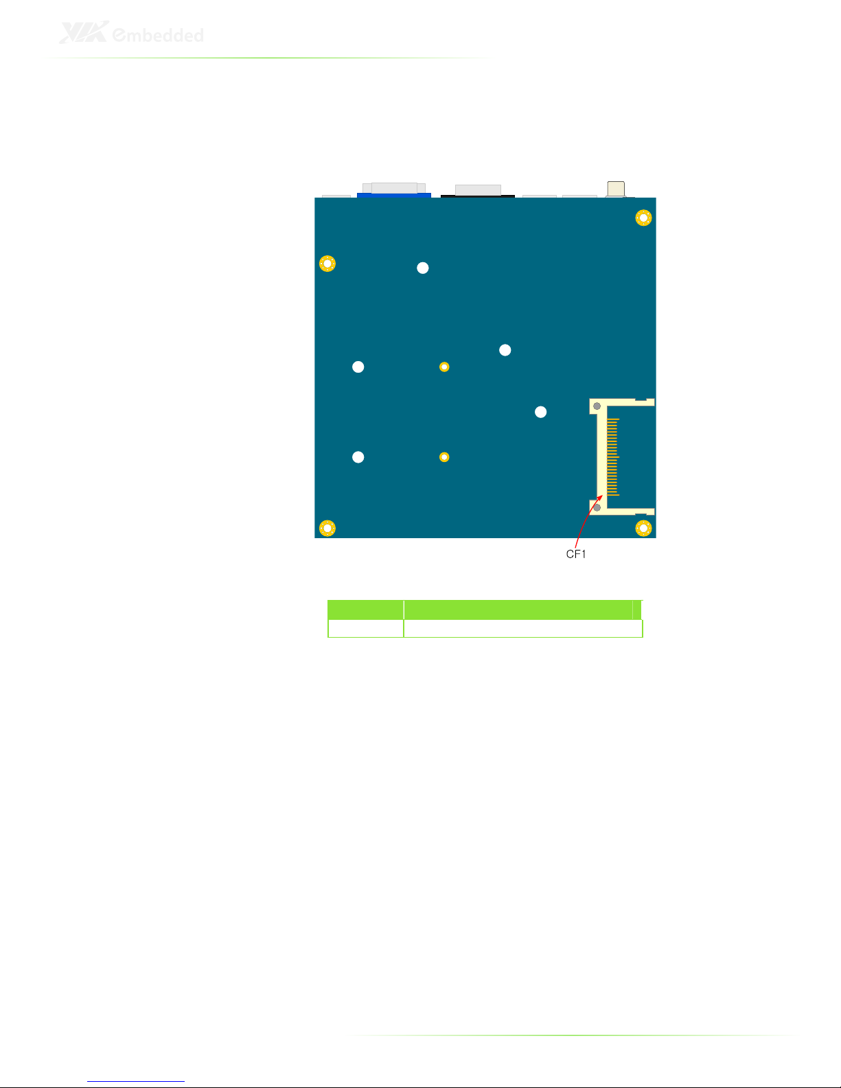
Bottom Side
Symbol
SymbolSymbol
Symbol
Description
DescriptionDescription
Description
CF1 Compact Flash connector
8
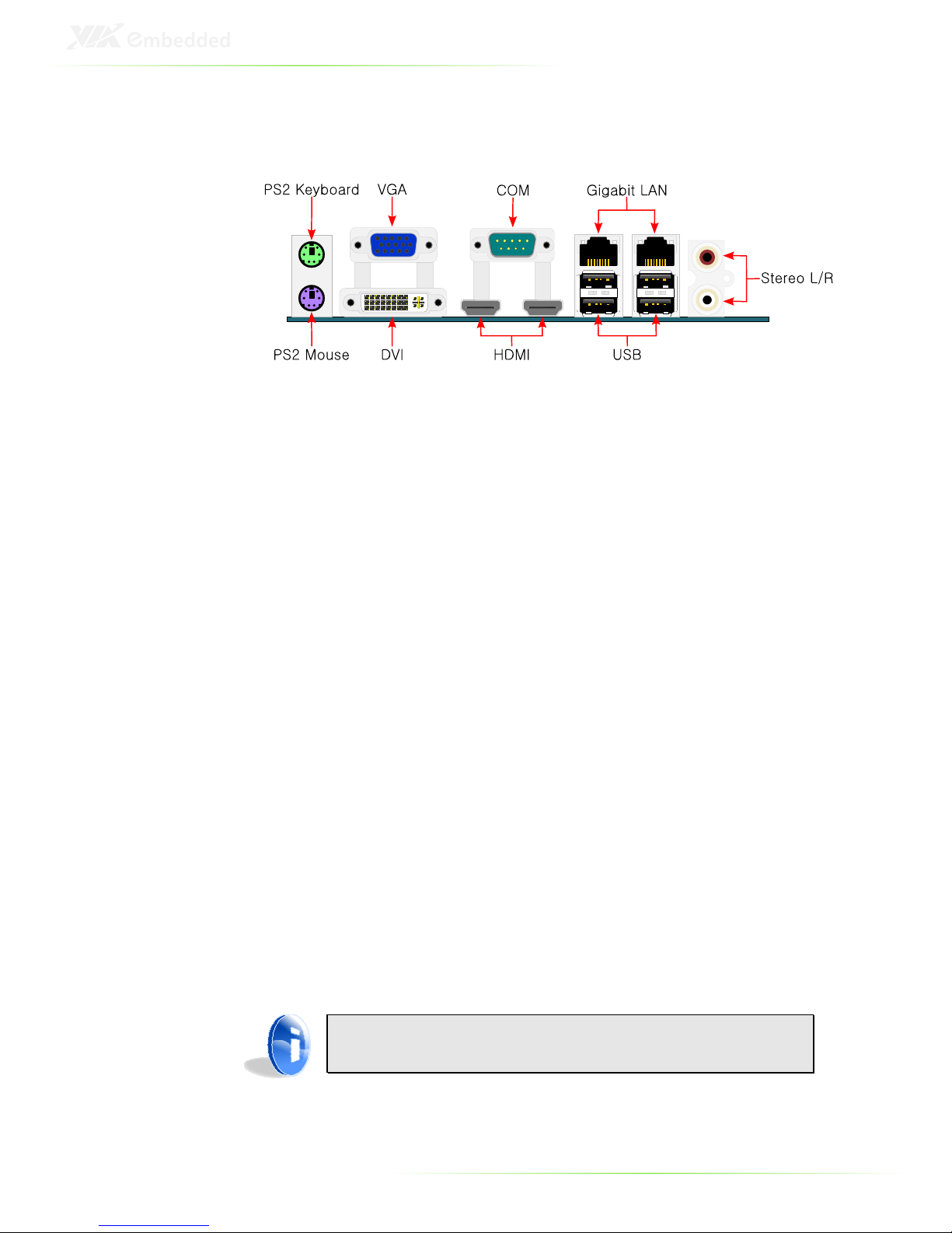
VB8003 BACK PANEL LAYOUT
PS2 Keyboard
The purple 6-pin connector is for a PS/2 keyboard.
PS2 Mouse
The green 6-pin connector is for a PS/2 mouse.
VGA port
The blue 15-pin female VGA port allows you to connect any
analog VGA monitor.
DVI port
The DVI-I connector allows you to connect to a DVI display.
COM port
The green 9-pin COM 1 port is for pointing devices or other serial
devices.
HDMI® port
The mainboard has two High Definition Multimedia Interface
(HDMI®) ports for connecting to high definition video and digital
audio. The HDMI® port connector allows you to connect digital
video devices which utilize a high definition video signal.
Note:
CEC feature is not supported.

9
Giga LAN port
The board provides one Gigabit Ethernet port controlled by a VIA
VT6130 Gigabit Ethernet controller. This port allows connection to
a Local Area Network (LAN) through a network hub.
USB port
The board provides four Universal Serial Bus (USB) ports on the
back panel for connecting USB 2.0 devices.
Stereo Right/Left jack
The red and white RCA jacks are for stereo audio output. The red
jack is the right channel and the white jack is the left channel.


11
2
Onboard
Connectors, Slots
and Pin Headers
This chapter provides you with information about hardware
installation procedures. It is recommended to use a grounded
wrist strap before handling computer components. Electrostatic
discharge (ESD) can damage some components.
12
TOP SIDE CONNECTORS
CPU
The VIA VB8003 Mini-ITX mainboard is packaged with a VIA Nano
1.6 GHz NanoBGA2. The processor requires a heatsink with fan to
provide sufficient cooling.
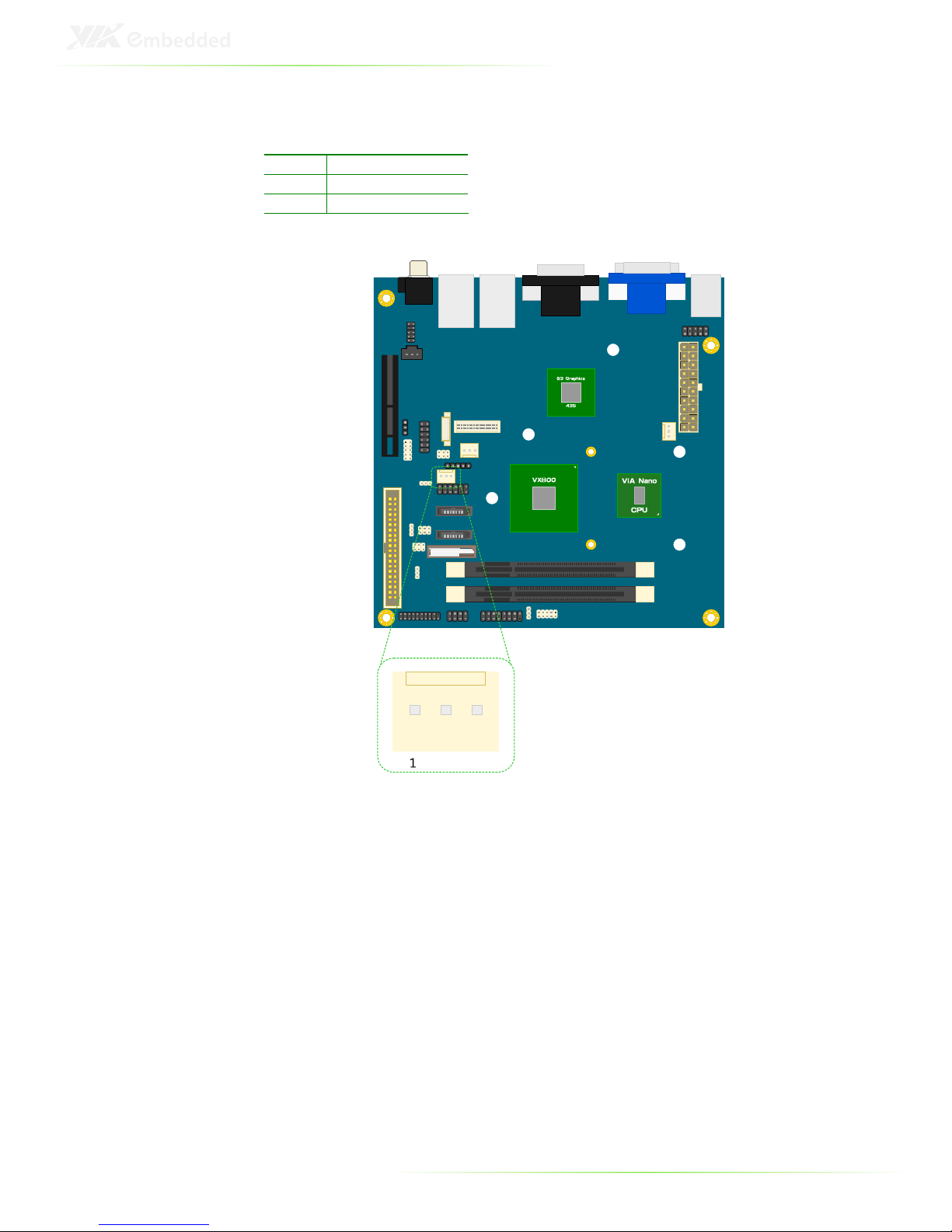
13
CPU and SYS Fan: CPUFAN1 and SYSFAN1
The CPUFAN (CPU fan) and SYSFAN (System fan) runs on +12V
and maintains CPU and system, cooling. When connecting the
cable to the connector, always be aware that the red wire
(positive wire) should be connected to the +12V pin. The black
wire is the ground wire and should always be connected to GND.
CPUFAN1
CPUFAN1CPUFAN1
CPUFAN1
Pin Signal
1 F_IO2
2 F_PWM2
3 GND
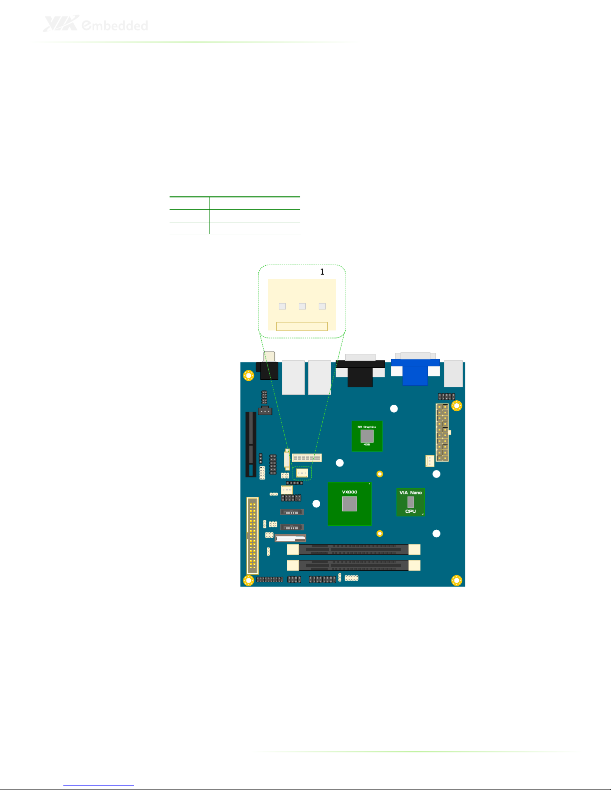
14
SYSFAN1
SYSFAN1SYSFAN1
SYSFAN1
Pin Signal
1 F_IO1
2 F_PWM1
3 GND
15
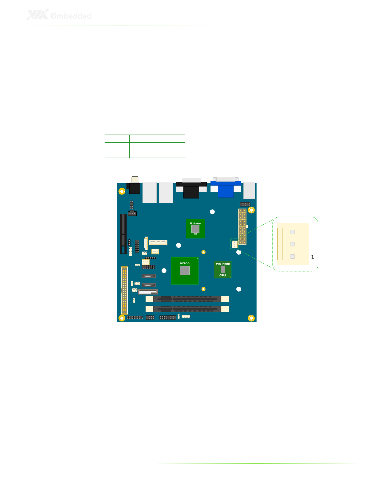
S3 Graphics Fan connector: S3FAN1
The S3FAN fan runs on +12V and maintains the cooling for the S3
Graphics chip. When connecting the cable to the connector,
always be aware that the red wire (positive wire) should be
connected to the +12V pin. The black wire is the ground wire and
should always be connected to GND.
Pin Signal
1 NC
2 +12V
3 GND
16
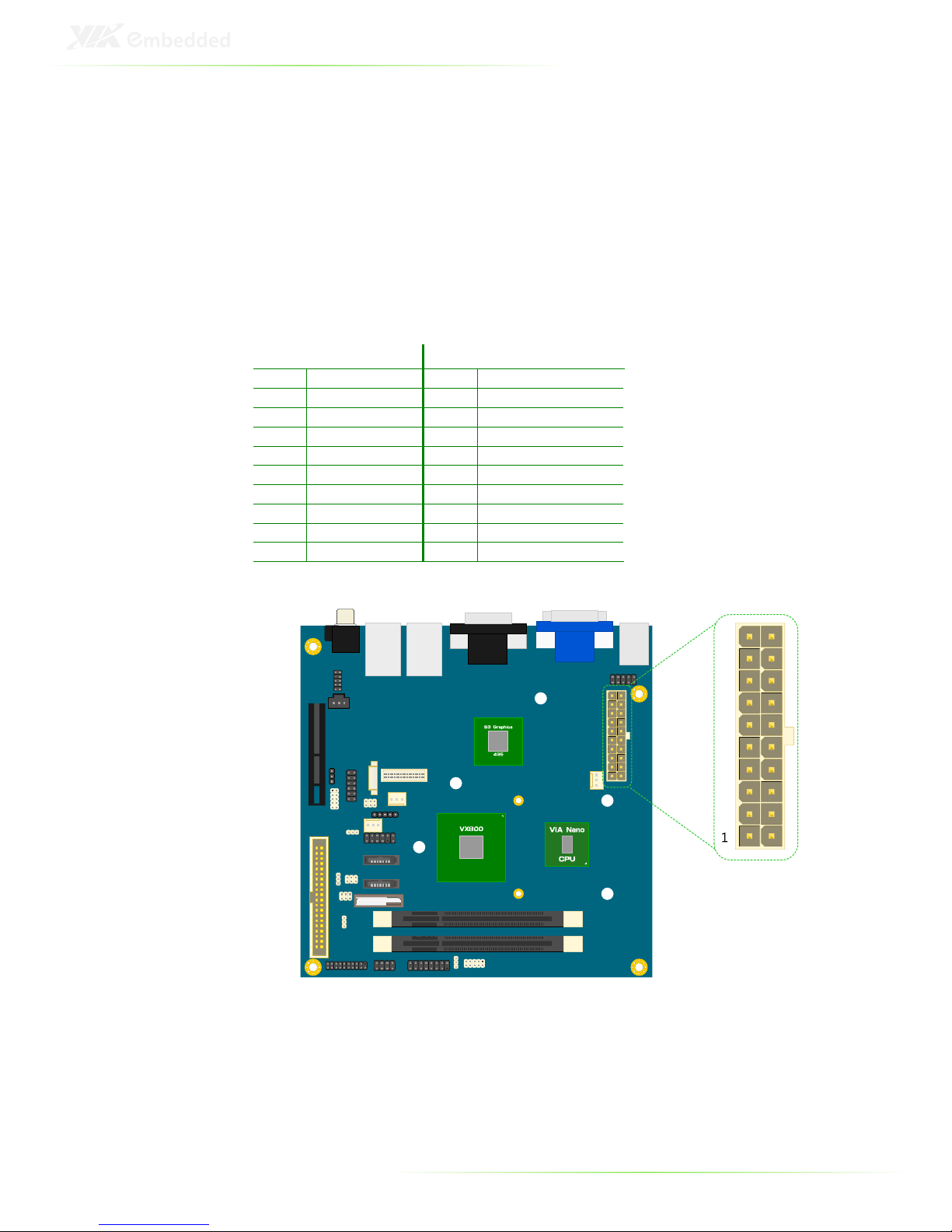
ATX 20-Pin Power connector: ATX_POWER1
The VIA VB8003 mainboard supports a conventional ATX power
supply. Before inserting the power supply connector, always make
sure that all components are installed correctly to ensure that no
damage will be caused.
To connect the power supply, make sure the power plug is
inserted in the proper orientation and the pins are aligned. Then
push the plug down firmly into the connector.
Pin Signal Pin Signal
1 +3.3V 11 +3.3V
2 +3.3V 12 -12V
3 GND 13 GND
4 +5V 14 Power Supply On
5 GND 15 GND
6 +5V 16 GND
7 GND 17 GND
8 Power Good 18 -5V
9 +5V Standby 19 +5V
10 +12V 20 +5V
17
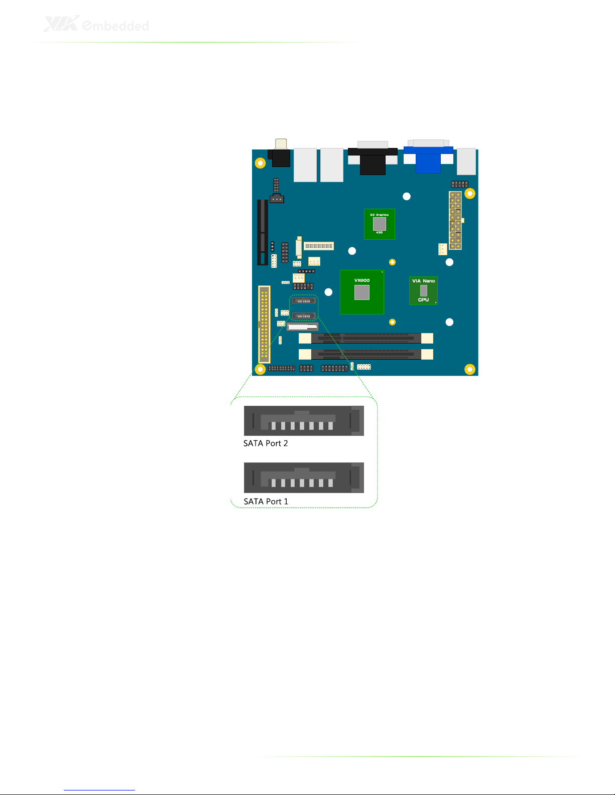
Serial ATA connectors: SATA1 and SATA2
The current SATA interface allows a data transfer rate of up to 300
MB/s — approximately 225% faster than Ultra DMA parallel ATA.
18
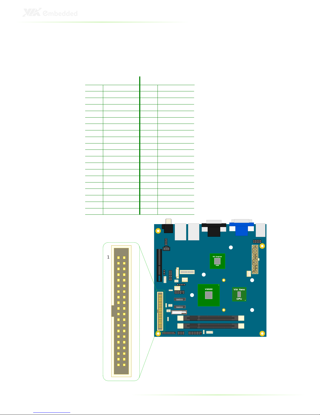
IDE pin header: IDE1
The mainboard has an Ultra DMA 133/100 controller. You can
connect up to two IDE devices in any combination.
Pin Signal Pin Signal
1 -IDE_RST 2 GND
3 PD_7 4 PD_8
5 PD_6 6 PD_9
7 PD_5 8 PD_10
9 PD_4 10 PD_11
11 PD_3 12 PD_12
13 PD_2 14 PD_13
15 PD_1 16 PD_14
17 PD_0 18 PD_15
19 GND 20 IDEV_SEL
21 PD_REQ 22 GND
23 -PD_IOW 24 GND
25 -PD_IOR 26 GND
27 PD_RDY 28 GND
29 -PD_ACK 30 GND
31 PD_IRQ15 32 NC
33 PD_A1 34 -LID
35 PD_A0 36 PD_A2
37 -PD_CS1 38 -PD_CS3
39 -HD_LED1 40 GND
19
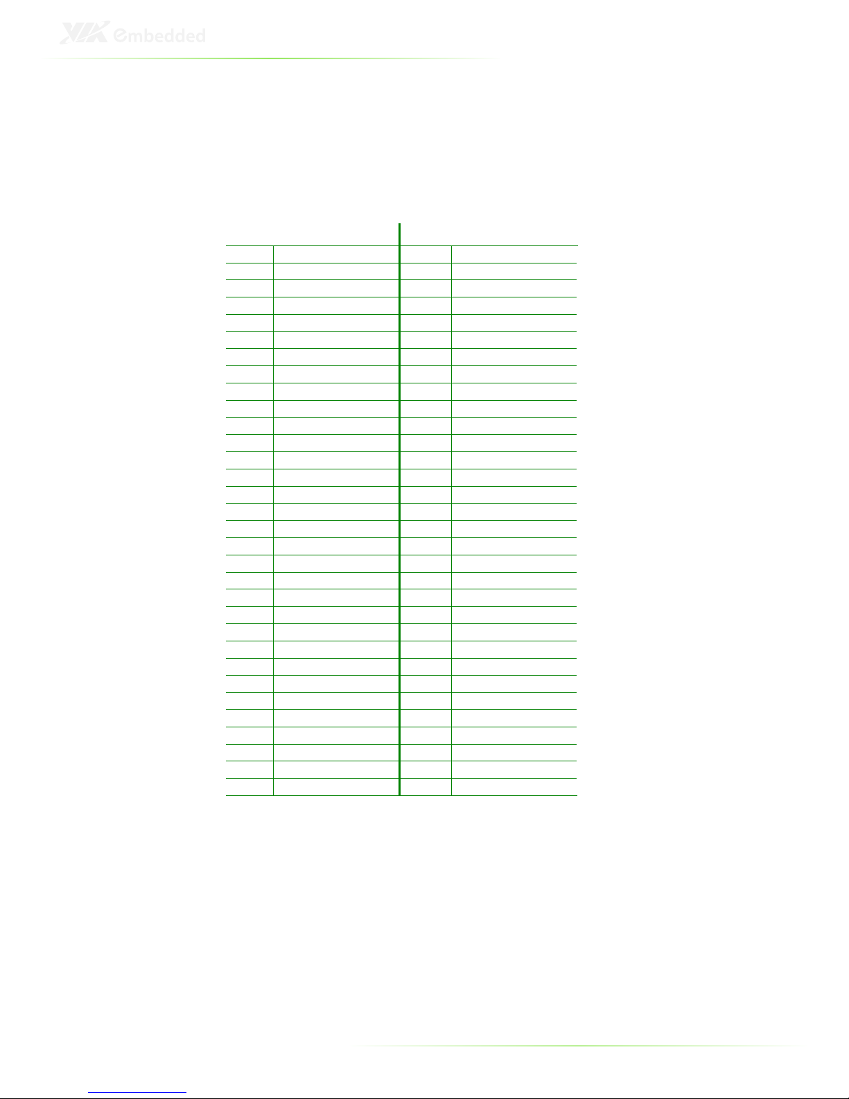
Video Capture Port: VCP1
The Video Capture Port (VCP) can support video capture or two
additional COM ports with 5V/12V power select (additional addon cards required).
Pin Signal Pin Signal
A1 -PCIRST B1 +5V
A2 +5V B2 +5V
A3 +5V B3 +5V
A4 GND B4 GND
A5 NC B5 DVP1_SPCLK
A6 +12V B6 DVP1_SPD
A7 +12V B7 GND
A8 NC B8 +3.3V
A9 +3.3V B9 NC
A10 +3.3V B10 +3.3V
A11 VCP_INTA- B11 NC
A12 GND B12 VCP_CLK_DSR4
A13 VCP_D15_DTR4 B13 GND
A14 VCP_D14 B14 VCP_D13
A15 GND B15 VCP_D12
A16 VCP_D11_R14 B16 GND
A17 VCP_D10_DCD4 B17 VCP_D9_SOUT4
A18 GND B18 GND
A19 VCP_D8_SIN4 B19 VCP_D7_CTS3
A20 GND B20 VCP_D6_RTS3
A21 VCP_D5_DSR3 B21 GND
A22 VCP_D4_DTR3 B22 GND
A23 GND B23 VCP_D3_SIN3
A24 GND B24 VCP_D2_SOUT3
A25 VCP_D1_DCD3 B25 GND
A26 VCP_D0_RI3 B26 GND
A27 GND B27 VCP_VS_RTS4
A28 GND B28 VCP_HS_CTS4
A29 AGND B28 GND
A30 LINE_IN_R B30 DVP1_DET
A31 GND B31 NC
A32 LINE_IN_L B32 GND

20
Note:
The Video Capture Port (VCP) slot is not a standard PCI Express
slot. Users will not be able to insert general PCI Express add-on
card.
21
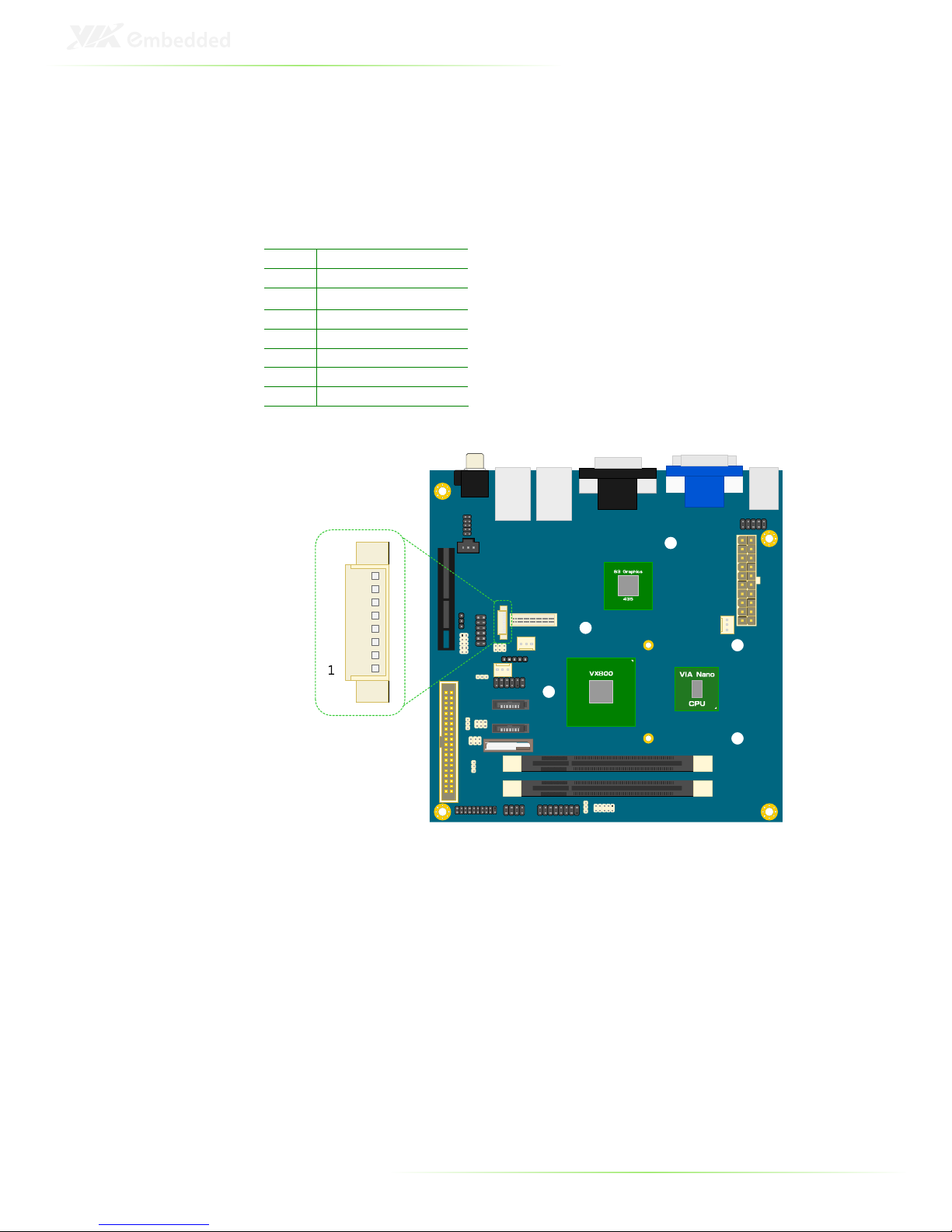
LVDS INVERTER connector: INVERTER1
The mainboard provides an inverter for supplying power to the
backlight of the LCD panel.
Pin Signal
1 IVDD1_CEN
2 IVDD1_CEN
3 BLON1
4 NC
5 BLON1
6 BRIGHTNESS1_CTL
7 GND
8 GND
 Loading...