

VIA Mainboard epia-n700 User Manual

EPIA
EPIA----N700
EPIAEPIA
N700
N700N700
User’s Manual
User’s Manual
User’s ManualUser’s Manual
Version 1.12
September 18, 2009

Copyright
Copyright
CopyrightCopyright
Copyright © 2008-2009 VIA Technologies Incorporated. All rights reserved.
No part of this document may be reproduced, transmitted, transcribed, stored in a retrieval system, or
translated into any language, in any form or by any means, electronic, mechanical, magnetic, optical,
chemical, manual or otherwise without the prior written permission of VIA Technologies, Incorporated.
Trademark
Trademarkssss
TrademarkTrademark
All trademarks are the property of their respective holders. PS/2 is a registered trademark of IBM
Corporation.
Disclaimer
Disclaimer
DisclaimerDisclaimer
No license is granted, implied or otherwise, under any patent or patent rights of VIA Technologies. VIA
Technologies makes no warranties, implied or otherwise, in regard to this document and to the products
described in this document. The information provided in this document is believed to be accurate and
reliable as of the publication date of this document. However, VIA Technologies assumes no responsibility
for the use or misuse of the information in this document and for any patent infringements that may arise
from the use of this document. The information and product specifications within this document are subject
to change at any time, without notice and without obligation to notify any person of such change.
FCC
FCC----B Radio Frequency Interference Statement
B Radio Frequency Interference Statement
FCCFCC
B Radio Frequency Interference StatementB Radio Frequency Interference Statement
This equipment has been tested and found to comply with the limits for a class B digital device, pursuant to
part 15 of the FCC rules. These limits are designed to provide reasonable protection against harmful
interference when the equipment is operated in a commercial environment. This equipment generates, uses
and can radiate radio frequency energy and, if not installed and used in accordance with the instruction
manual, may cause harmful interference to radio communications. Operation of this equipment in a
residential area is likely to cause harmful interference, in which case the user will be required to correct the
interference at his personal expense.
Notice 1
Notice 1
Notice 1Notice 1
The changes or modifications not expressly approved by the party responsible for compliance could void the
user's authority to operate the equipment.
Notice 2
Notice 2
Notice 2Notice 2
Shielded interface cables and A.C. power cord, if any, must be used in order to comply with the emission
limits.
Tested To Comply
With FCC Standards
FOR HOME OR OFFICE USE
ii
ii
iiii
SSSS
AFETY
AFETY
IIII
NSTRUCTIONS
AFETY AFETY
NSTRUCTIONS
NSTRUCTIONSNSTRUCTIONS
Always read the safety instructions carefully.
Keep this User's Manual for future reference.
Keep this equipment away from humidity.
Lay this equipment on a reliable flat surface before setting it up.
The openings on the enclosure are for air convection hence protects the
equipment from overheating. Do not cover the openings.
Make sure the voltage of the power source and adjust properly 110/220V
before connecting the equipment to the power inlet.
Place the power cord in such a way that people cannot step on it. Do not
place anything over the power cord.
Always unplug the power cord before inserting any add-on card or module.
All cautions and warnings on the equipment should be noted.
Never pour any liquid into the opening. Liquid can cause damage or
electrical shock.
If any of the following situations arises, get the equipment checked by a
service personnel:
The power cord or plug is damaged.
Liquid has penetrated into the equipment.
The equipment has been exposed to moisture.
The equipment has not worked well or you cannot get it work
according to User's Manual.
The equipment has dropped and damaged.
If the equipment has obvious sign of breakage.
Do not leave this equipment in an environment unconditioned or in a
storage temperature above 60oC (140oF). The equipment may be damaged.
Caution:
Caution:
Caution:Caution:
Only use the appropriate battery specified for this product.
Do not reuse, recharge, or reheat an old battery.
Do not attempt to force open the battery.
Do not discard used batteries with regular trash.
Discard used batteries according to local regulations.
iii
iii
iiiiii

TTTT
ABLE OF
ABLE OF
ABLE OF ABLE OF
Safety Instructions ........................................................................................................... iii
Table of Contents............................................................................................................. iv
CCCC
hhhh
aaaa
pppp
CCCC
hhhh
aaaa
CCCC
hhhh
aaaa
Mainboard Specifications.........................................................................................2
Mainboard Layout .......................................................................................................4
Back Panel Layout........................................................................................................5
CCCC
hhhh
aaaa
pppp
CCCC
hhhh
aaaa
CCCC
hhhh
aaaa
CPU ....................................................................................................................................8
Memory Module Installation...................................................................................9
Power Connectors.....................................................................................................11
Back Panel Ports ........................................................................................................ 13
Connectors................................................................................................................... 14
Jumpers......................................................................................................................... 20
CCCC
ONTENTS
ONTENTS
ONTENTSONTENTS
tttt
eeee
rrrr
1111
pppp
tttt
eeee
rrrr
1111
pppp
tttt
eeee
rrrr
1111
Specifications.................................................................................................1
tttt
eeee
rrrr
2222
pppp
tttt
eeee
rrrr
2222
pppp
tttt
eeee
rrrr
2222
Installation ......................................................................................................7
CPU Fan and System Fan: CPU_FAN and SYS_FAN ..................................8
Memory Slot: DDR2 SODIMM SDRAM..........................................................9
DDR2 SDRAM Module Installation Procedures .........................................9
Available DDR2 SDRAM Configurations .................................................... 10
ATX 4-Pin Power Connector: DC12V ........................................................... 11
SATA Power: S-Power ........................................................................................ 11
External CMOS Battery Connector: BAT1...................................................12
VGA Port.................................................................................................................. 13
COM (Serial) Port ................................................................................................. 13
USB Ports................................................................................................................. 13
RJ-45 LAN Port...................................................................................................... 13
IDE Connector: IDE.............................................................................................. 14
SATA Ports ..............................................................................................................15
USB Pin Connector: USB 2/3 ...........................................................................15
Front Panel: F_Panel............................................................................................ 15
KB/MS Connector ................................................................................................16
Digital I/O: DIO ..................................................................................................... 16
SPI (Serial Peripheral Interface): JSPI ........................................................... 16
Front Panel Audio: F_Audio ............................................................................. 17
Serial Port: COM2/COM3/COM4 .................................................................. 17
LVDS Panel Connector.......................................................................................18
LVDS Inverter Connector: INVERTER ...........................................................18
System Management Bus: SMBus ................................................................19
System Temperature Sensor: SEN ................................................................ 19
Clear CMOS............................................................................................................ 20
CF Master Select: MS_CF_SEL.......................................................................... 20
AT/ATX Power ....................................................................................................... 21
iv
iv
iviv

Panel Power Selector: PVDD_SEL .................................................................. 21
Inverter Selector: IVDD_SEL ............................................................................. 21
COM2 Power Select: J3...................................................................................... 22
RS232/RS422/RS485 Select ............................................................................. 22
Slots ................................................................................................................................ 23
Mini Peripheral Component Interconnect: MiniPCI ..............................23
PCI Interrupt Request Routing ....................................................................... 23
Compact Flash Type I Connector: CF...........................................................23
CCCC
hhhh
aaaa
pppp
tttt
eeee
rrrr
CCCC
CCCC
3333
hhhh
aaaa
pppp
tttt
eeee
rrrr
3333
hhhh
aaaa
pppp
tttt
eeee
rrrr
3333
BIOS Setup....................................................................................................25
Entering the BIOS Setup Menu ........................................................................... 26
Control Keys ................................................................................................................27
Navigating the BIOS Menus ................................................................................. 28
Getting Help................................................................................................................ 29
Main Menu................................................................................................................... 30
Standard CMOS Features ................................................................................. 30
Advanced BIOS Features................................................................................... 30
Advanced Chipset Features ............................................................................. 30
Integrated Peripherals ....................................................................................... 30
Power Management Setup .............................................................................. 30
PnP/PCI Configurations..................................................................................... 30
PC Health Status................................................................................................... 31
Frequency/Voltage Control ............................................................................. 31
Load Optimized Defaults.................................................................................. 31
Set Supervisor Password................................................................................... 31
Set User Password ............................................................................................... 31
Save & Exit Setup................................................................................................. 31
Exit Without Saving............................................................................................. 31
Standard CMOS Features ...................................................................................... 32
Date ........................................................................................................................... 32
Time........................................................................................................................... 32
Video.........................................................................................................................32
Halt On..................................................................................................................... 32
IDE Drives ..................................................................................................................... 33
IDE Channel 0 Master......................................................................................... 33
IDE Channel 0 Slave ............................................................................................ 33
IDE Channel 1 Master......................................................................................... 34
IDE Channel 1 Slave ............................................................................................ 34
Advanced BIOS Features........................................................................................ 36
Virus Warning........................................................................................................ 36
CPU L1 & L2 Cache ............................................................................................. 36
CPU L2 Cache ECC Checking........................................................................... 36
Quick Power On Self-Test ................................................................................ 37
First/Second/Third Boot Device..................................................................... 37
vvvv

Boot Other Device............................................................................................... 37
Boot Up NumLock Status ................................................................................. 37
Typematic Rate Setting ..................................................................................... 37
Typematic Rate (Chars/Sec)............................................................................. 38
Typematic Delay (Msec).................................................................................... 38
Security Option..................................................................................................... 38
MPS Version Control for OS............................................................................ 38
OS Select for DRAM > 64MB.......................................................................... 38
HDD S.M.A.R.T Capability.................................................................................38
Video BIOS Shadow............................................................................................ 38
Full Screen Logo Show ...................................................................................... 38
Summary Screen Show...................................................................................... 39
CPU Features...............................................................................................................40
Delay Prior to Thermal.......................................................................................40
Thermal Management ....................................................................................... 40
Hard Disk Boot Priority........................................................................................... 41
Advanced Chipset Features .................................................................................. 42
Memory Hole.........................................................................................................42
System BIOS Cacheable .................................................................................... 42
Video RAM Cacheable .......................................................................................42
AGP Fast Write ...................................................................................................... 42
Select Display Device ......................................................................................... 42
Panel Type............................................................................................................... 42
Internal VGA Control ............................................................................................... 43
AGP 3.0 Calibration Cycle................................................................................. 43
VGA Share Memory Size................................................................................... 43
Direct Frame Buffer............................................................................................. 43
Outport Port........................................................................................................... 43
Dithering.................................................................................................................. 43
CPU & PCI Bus Control ........................................................................................... 44
PCI Master 0 WS Write ...................................................................................... 44
PCI Delay Transaction ........................................................................................ 44
VIA PWR Management...................................................................................... 44
Integrated Peripherals............................................................................................. 45
OnChip IDE Channel 1 ....................................................................................... 45
IDE HDD Block Mode ......................................................................................... 45
SATA Controller .................................................................................................... 45
Azalia HDA Controller........................................................................................ 45
Onboard LAN Boot ROM..................................................................................45
VIA Wireless LAN Support ............................................................................... 45
Super IO Device ......................................................................................................... 46
Onboard Serial Port 1 ........................................................................................ 46
Onboard Serial Port 2 ........................................................................................ 46
vi
vi
vivi

Onboard Serial Port 3 ........................................................................................ 46
Onboard Serial Port 4 ........................................................................................ 46
WatchDog Support ............................................................................................. 46
VIA OnChip IDE Device........................................................................................... 47
IDE Prefetch Mode .............................................................................................. 47
CF Card UDMA66................................................................................................. 47
IDE DMA Transfer Access ................................................................................. 47
Secondary Master PIO ....................................................................................... 47
Secondary Slave PIO........................................................................................... 47
Secondary Master UDMA................................................................................. 47
Secondary Slave UDMA .................................................................................... 47
USB Device Setting................................................................................................... 48
USB 1.0 Controller ............................................................................................... 48
USB 2.0 Controller ............................................................................................... 48
USB Operation Mode......................................................................................... 48
USB Keyboard Function .................................................................................... 48
USB Mouse Function .......................................................................................... 49
USB Storage Function ........................................................................................ 49
Power Management Setup ................................................................................... 50
ACPI Suspend Type............................................................................................. 50
Power Management Option............................................................................ 50
HDD Power Down................................................................................................ 50
Suspend Mode...................................................................................................... 51
Video Off Option.................................................................................................. 51
Video Off Method................................................................................................51
Soft-Off by PWRBTN .......................................................................................... 51
Run VGABIOS if S3 Resume............................................................................. 51
AC Loss Auto Restart..........................................................................................51
Wakeup Event Detect..............................................................................................52
PS2KB Wakeup Select ........................................................................................52
PS2KB Wakeup Key Select ............................................................................... 52
PS2MS Wakeup Key Select .............................................................................. 52
PS2 Keyboard Power On................................................................................... 52
PS2 Mouse Power On ........................................................................................ 53
USB Resume from S3 ......................................................................................... 53
Wakeup On GPI .................................................................................................... 53
PowerOn by PCI Card......................................................................................... 53
RTC Alarm Resume.............................................................................................. 53
Date (of Month).................................................................................................... 53
Resume Time (hh : mm : ss).............................................................................53
PnP/PCI Configurations.......................................................................................... 54
Init Display First .................................................................................................... 54
PNP OS Installed ..................................................................................................54
vii
vii
viivii

Reset Configuration Data.................................................................................54
Resources Controlled By................................................................................... 55
PCI/VGA Palette Snoop ..................................................................................... 55
Assign IRQ for VGA............................................................................................. 55
Assign IRQ for USB.............................................................................................. 55
Maximum Payload Size ..................................................................................... 55
PC Health Status........................................................................................................ 56
Frequency/Voltage Control .................................................................................. 57
DRAM Frequency................................................................................................. 57
DRAM Channel Mode ........................................................................................ 57
DDR CAS Latency Control ................................................................................ 57
DDR Burst Length ................................................................................................ 57
DDR 1T Command Rate.................................................................................... 57
DRDY Table............................................................................................................. 57
ODT............................................................................................................................ 57
Spread Spectrum .................................................................................................58
Load Optimized Defaults .......................................................................................59
Set Supervisor/User Password............................................................................. 60
Set Supervisor ....................................................................................................... 60
User Password....................................................................................................... 60
Save & Exit Setup...................................................................................................... 62
Exit Without Saving.................................................................................................. 63
CCCC
hhhh
aaaa
pppp
tttt
eeee
rrrr
CCCC
CCCC
4444
hhhh
aaaa
pppp
tttt
eeee
rrrr
4444
hhhh
aaaa
pppp
tttt
eeee
rrrr
4444
Driver Installation.......................................................................................65
Driver Utilities ............................................................................................................. 66
Getting Started ..................................................................................................... 66
Running the Driver Utilities CD...................................................................... 67
CD Content ..................................................................................................................68
viii
viii
viiiviii

EPIA-N700 User’s Manual
CCCC
HHHH
AAAA
PPPP
TTTT
EEEE
RRRR
CCCC
HHHH
AAAA
PPPP
AAAA
PPPP
TTTT
TTTT
CCCC
HHHH
S
PECIFICATIONS
The ultra-compact and highly integrated VIA EPIA-N700 uses the NanoITX mainboard form-factor developed by VIA Technologies, Inc. as part
of the company’s open industry-wide total connectivity initiative. The
mainboard enables the creation of an exciting new generation of small,
ergonomic, innovative and affordable embedded systems. Through a
high level of integration, the Nano-ITX occupy 50% of the size of a MiniATX mainboard form factor. The mainboard comes with a VIA C7
NanoBGA2 Processor, boasting of ultra-low power consumption, cool
and quiet operation.
EEEE
EEEE
RRRR
RRRR
1111
1111
1111
1111

EPIA-N700 User’s Manual
Mainboard Specifications
Mainboard Specifications
Mainboard SpecificationsMainboard Specifications
CPU
CPU
CPUCPU
• VIA C7 1.5GHz NanoBGA2 processor
Chipset
Chipset
ChipsetChipset
• VIA VX800 advanced all-in-one system processor
Graphics
Graphics
GraphicsGraphics
• Integrated VIA Chrome9™ HC Integrated Graphics 3D/2D and
Unified Video Decoding Accelerator
Audio
Audio
AudioAudio
• VIA VT1708B High Definition Audio Codec
Memory
Memory
MemoryMemory
• 1 x DDR2 667/533 SODIMM slot (up to 2 GB)
Expansion Slot
Expansion Slot
Expansion SlotExpansion Slot
• 1 x MiniPCI slot
IDE
IDE
IDEIDE
• 1 x UltraDMA 133/100/66/33 pin header
LAN
LAN
LANLAN
• 1 x VIA VT6130 PCIe Gigabit Ethernet Controller
Onboard I/O Connectors
Onboard I/O Connectors
Onboard I/O ConnectorsOnboard I/O Connectors
• 1 x USB pin header for 2 additional USB 2.0 ports
• 1 x Dual-channel LVDS panel connector
• 1 x Backlight control connector for inverter power and
brightness control
• 1 x CF (Compact Flash) type I connector (shared with IDE)
• 1 x KB/MS pin header
• 3 x Serial port header (RS-232) with one 5V/12V select jumper
• 1 x Digital I/O pin header
• 1 x SPI pin header
• 1 x Front Panel pin header
• 1 x Front-audio pin header
• 1 x SMBus pin header
• 2 x SATA port connectors
• 2 x Fan connectors for CPU and System fans
• 1 x System temperature reading pin header
• 2 x +5V Power header for 2.5” SATA HDD
• 1 x +12V Power connector
• 1 x Power mode select connector (AT, ATX)
2222

EPIA-N700 User’s Manual
Back Panel I/O Ports
Back Panel I/O Ports
Back Panel I/O PortsBack Panel I/O Ports
• 1 x Serial port
• 1 x RJ45 LAN port
• 1 x VGA port
• 2 x USB 2.0 ports
BIOS
BIOS
BIOSBIOS
• Award BIOS with SPI 4/8Mbit flash memory capacity
Form Factor
Form Factor
Form FactorForm Factor
• Nano-ITX
• 12cm X 12cm
3333
EPIA-N700 User’s Manual
Mainboard Layout
Mainboard Layout
Mainboard LayoutMainboard Layout
(Top View)
(Bottom View)
4444
EPIA-N700 User’s Manual
Back Panel Layout
Back Panel Layout
Back Panel LayoutBack Panel Layout
5555

EPIA-N700 User’s Manual
This page is intentionally left blank.
6666

EPIA-N700 User’s Manual
CCCC
HHHH
AAAA
PPPP
TTTT
EEEE
RRRR
CCCC
HHHH
AAAA
PPPP
AAAA
PPPP
TTTT
TTTT
CCCC
HHHH
I
NSTALLATION
This chapter provides you with information about hardware installation
procedures. It is recommended to use a grounded wrist strap before
handling computer components. Electrostatic discharge (ESD) can
damage some components.
EEEE
EEEE
RRRR
RRRR
2222
2222
2222
7777
EPIA-N700 User’s Manual
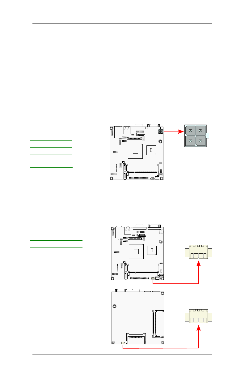
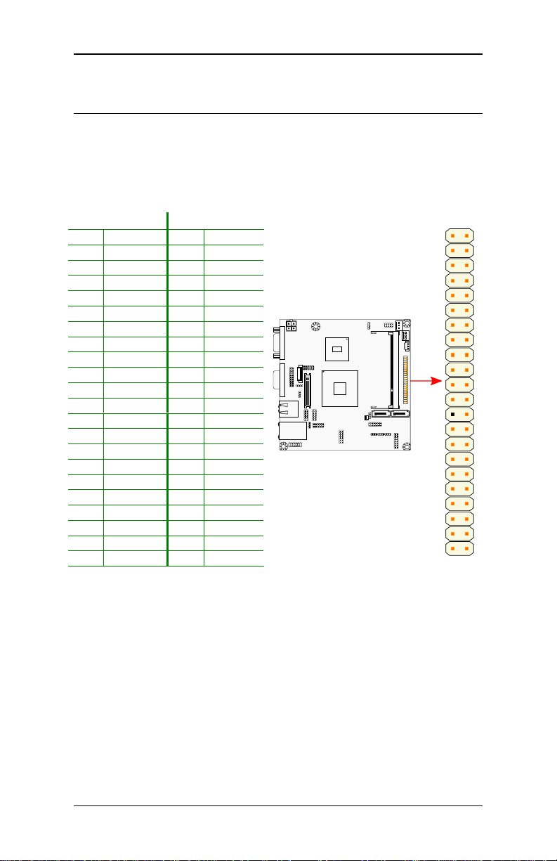
1111
CPU_FAN
CPU_FANCPU_FAN
CPU_FAN
SYS_FAN
SYS_FANSYS_FAN
SYS_FAN
1111
CPU
CPU
CPUCPU
The VIA EPIA-N700 mainboard is packaged with a standard VIA C7 1.5
GHz NanoBGA2 processor. The processor requires a heatsink with fan to
provide sufficient cooling.
CPU Fan and System Fan: CPU_FAN and SYS_FAN
The CPU_FAN (CPU fan) and SYS_FAN (system fan) run on +12V and
maintain system cooling. When connecting the wire to the connectors,
always be aware that the red wire (positive wire) should be connected to
the +12V. The black wire is Ground and should always be connected to
GND.
Pin
Pin Signal
PinPin
1 F_IO2
2 +12V
3 GND
Pin
Pin Signal
PinPin
1 F_IO1
2 +12V
3 GND
Signal
SignalSignal
Signal
SignalSignal
8888
EPIA-N700 User’s Manual
Memory Mo
Memory Moddddule Installation
Memory MoMemory Mo
ule Installation
ule Installationule Installation
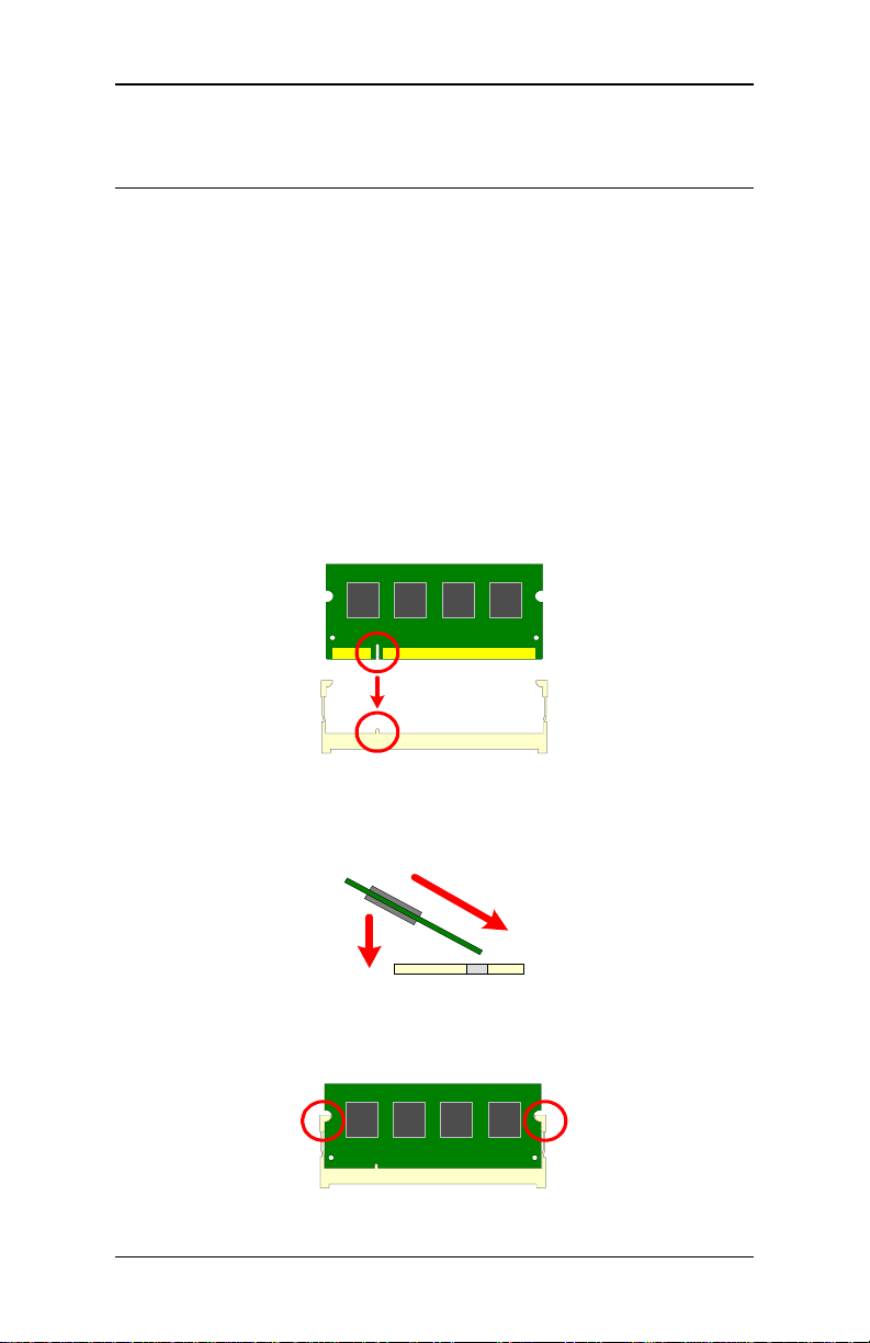
Memory Slot: DDR2 SODIMM SDRAM
The VIA EPIA-N700 mainboard provide one 200-pin SODIMM slot for
DDR2 667/533 SDRAM memory modules and supports memory sizes up
to 2GB.
DDR2 SDRAM Module Installation Procedures
Step 1
Step 1
Step 1Step 1
Locate the SODIMM slot in the mainboard.
Step 2
Step 2
Step 2Step 2
Align the notch on the SODIMM with the memory slot.
Step 3
Step 3
Step 3Step 3
Inset the SODIMM module at a 45 degree angle.
Step 4
Step 4
Step 4Step 4
Then push the SODIMM down until it snaps into the locking mechanism.
1
2
9999

EPIA-N700 User’s Manual
Available DDR2 SDRAM Configurations
Refer to the table below for available DDR2 SDRAM configurations on
the mainboard.
Slot
Slot Module Size
SlotSlot
SODIMM 64MB, 128MB, 256MB, 512MB, 1GB, 2GB 64MB - 2GB
Maximum supported system memory 2GB
Module Size Total
Module SizeModule Size
Total
TotalTotal
10
10
1010
EPIA-N700 User’s Manual
1111
1111
1111
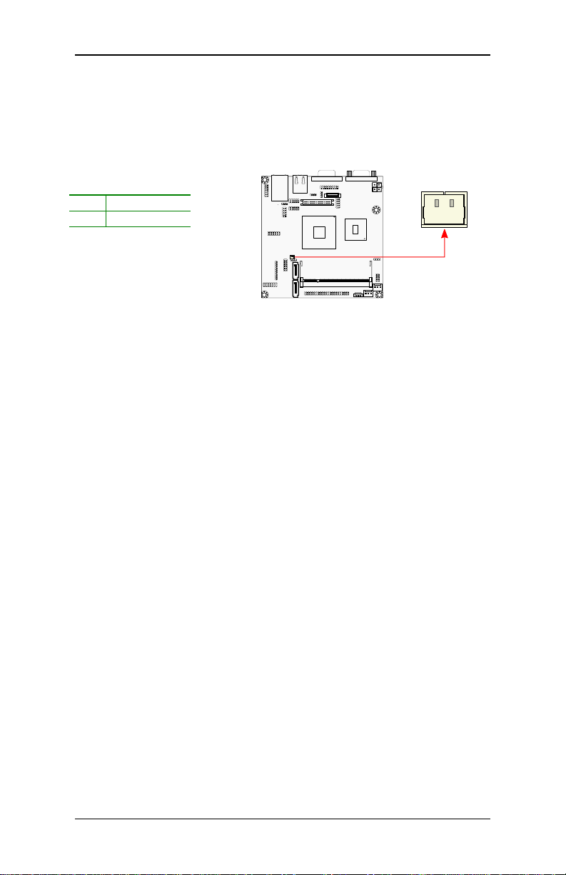
Power Connectors
Power Connectors
Power ConnectorsPower Connectors
The VIA EPIA-N700 mainboard supports a 4-pin ATX power connector
for the system power input. Before inserting the power supply connector,
always make sure that all components are installed correctly to ensure
that no damage will be caused.
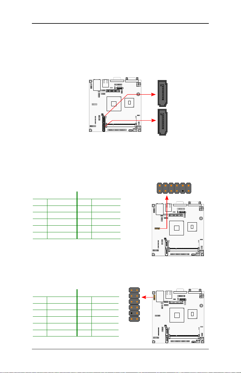
ATX 4-Pin Power Connector: DC12V
To connect the power supply, make sure the power plug is inserted in
the proper orientation and the pins are aligned. Then push down the
plug firmly into the connector.
Pin
Pin Signal
Signal
PinPin
SignalSignal
1 GND
2 GND
3 DC_12V
4 DC_12V
SATA Power: S-Power
The mainboard supports two 3-pin SATA power connectors for SATA
power cable. Plug the SATA power cable into the SATA power connector.
Make sure the power plug is inserted in the proper orientation.
Pi
Pinnnn Signal
Signal
PiPi
SignalSignal
1 GND
2 +5V
3 +5V
11
11
1111
EPIA-N700 User’s Manual
1111
External CMOS Battery Connector: BAT1
The mainboard comes with external CMOS battery connector. This 2-pin
connector used to connect the external cable battery.
Pin
Pin Signal
Signal
PinPin
SignalSignal
1 A3V (+3.0V)
2 GND
12
12
1212
EPIA-N700 User’s Manual
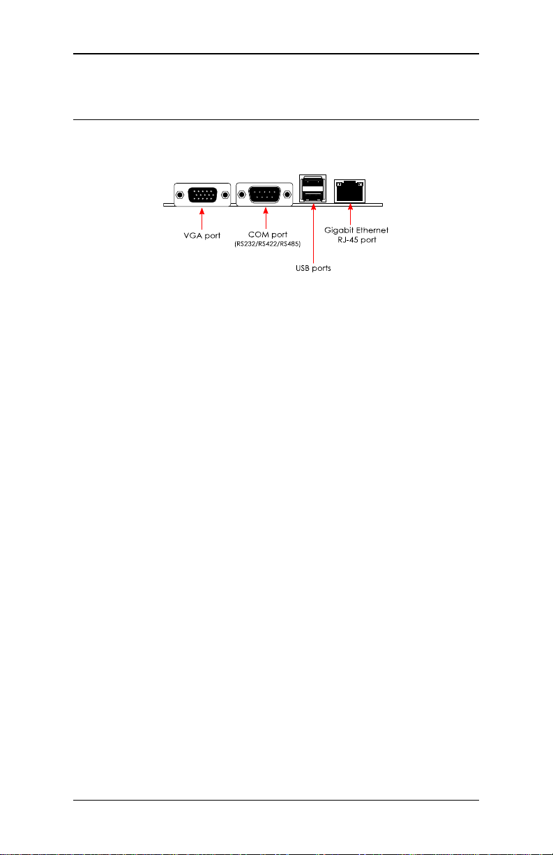
Back
Back Panel Ports
Back Back
The back panel has the following ports:
Panel Ports
Panel PortsPanel Ports
VGA Port
The VGA port allows you to connect any analog VGA monitor.
COM (Serial) Port
The 9-pin COM port is for pointing devices or other serial devices.
USB Ports
Two standard USB 2.0 ports are provided on the back panel. These ports
are used to connect the USB2.0 devices.
RJ-45 LAN Port
The board provides a standard RJ-45 (Gigabit Ethernet). This port allows
the connection to a Local Area Network (LAN) through a network hub.
13
13
1313
EPIA-N700 User’s Manual
Pin
PinPin
Pin
Signal
SignalSignal
Signal
Pin
PinPin
Pin
Signal
SignalSignal
Signal
1111 2222
43
4343
43 44
4444
44
Connectors
Connectors
ConnectorsConnectors
IDE Connector: IDE
The mainboard has an Ultra DMA 133/100/66/33 controller. You can
connect up to two IDE devices in any combination.
1 #IDERST 2 GND
3 PDD7 4 PDD8
5 PDD6 6 PDD9
7 PDD5 8 PDD10
9 PDD4 10 PDD11
11 PDD3 12 PDD12
13 PDD2 14 PDD13
15 PDD1 16 PDD14
17 PDD0 18 PDD15
19 GND 20 KEY
21 PDDREQ 22 GND
23 #PDIOW 24 GND
25 #PDIOR 26 GND
27 PIORDY 28 GND
29 #PDDACK 30 GND
31 IRQ15 32 NC
33 PDA1 34 GPI0
35 PDA0 36 PDA2
37 #PDCS1 38 #PDCS3
39 #HD_LED1 40 GND
41 +5V 42 +5V
43 GND 44 NC
If two drives are connected to a single cable, the jumper on the second
drive must be set to slave mode. Refer to the drive documentation
supplied by the vendor for the jumper settings.
14
14
1414
EPIA-N700 User’s Manual
11
1111
11
1111 2222
1111
2222
1111
2222 1111
2222
1111
1111
Port 1
Port 1Port 1
Port 1
Port 2
Port 2Port 2
Port 2
SATA Ports
These next generation connectors support the thin SATA cables for
primary internal storage devices. The current SATA interface allows up to
300MB/s data transfer rate, faster than the standard parallel ATA with
133 MB/s (UltraDMA).
USB Pin Connector: USB 2/3
The mainboard provides 2 USB ports and one USB pin header (allowing
up to two additional USB 2.0 ports). Therefore mainboard can support
up to four USB 2.0 ports. These ports can be used to connect highspeed USB interface peripherals such as USB HDD, digital cameras, MP3
players, printers, modem and the like.
Pin
Pin Signal
Signal Pin
PinPin
SignalSignal
1 VUSB 2 VUSB
3 USBD_T0- 4 USBD_T15 USBD_T0+ 6 USBD_T1+
7 GND 8 GND
9 Key 10 NC
11 GND 12 GPO9
Pin Signal
Signal
PinPin
SignalSignal
Front Panel: F_Panel
The F_Panel pin header allows you to connect the power switch, reset
switch, power LED, HDD LED and the case speaker.
Pin
Pin Signal
Signal Pin
PinPin
SignalSignal
1 +PWR_LED 2 +HD_LED
3 +PWR_LED 4 -HD_LED
5 -PWR_LED 6 PW_BN
7 SPEAK+ 8 GND
9 Key 10 RST_SW
11 SPEAK- 12 GND
Pin Signal
Signal
PinPin
SignalSignal
15
15
1515
 Loading...