

Page 1

Revision
1
.02
102-0625
2012-1125
user manual
ARTiGO-A1150
Barebone System with
EPIA-P900 Embedded Board
Page 2
Copyright and Trademarks
Copyright © 2011-2012 VIA Technologies Incorporated. All rights reserved.
No part of this document may be reproduced, transmitted, transcribed, stored in a
retrieval system, or translated into any language, in any form or by any means, electronic,
mechanical, magnetic, optical, chemical, manual or otherwise without the prior written
permission of VIA Technologies, Incorporated.
All trademarks are the property of their respective holders.
PS/2 is a registered trademark of IBM Corporation.
Disclaimer
No license is granted, implied or otherwise, under any patent or patent rights of VIA
Technologies. VIA Technologies makes no warranties, implied or otherwise, in regard to
this document and to the products described in this document. The information provided
in this document is believed to be accurate and reliable as of the publication date of this
document. However, VIA Technologies assumes no responsibility for the use or misuse of
the information in this document and for any patent infringements that may arise from the
use of this document. The information and product specifications within this document are
subject to change at any time, without notice and without obligation to notify any person
of such change.
Regulatory Compliance
FCC-A Radio Frequency Interference Statement
This equipment has been tested and found to comply with the limits for a class B digital
device, pursuant to part 15 of the FCC rules. These limits are designed to provide
reasonable protection against harmful interference when the equipment is operated in a
commercial environment. This equipment generates, uses, and can radiate radio
frequency energy and, if not installed and used in accordance with the instruction manual,
may cause harmful interference to radio communications. Operation of this equipment in a
residential area is likely to cause harmful interference, in which case the user will be
required to correct the interference at his personal expense.
Notice 1
The changes or modifications not expressly approved by the party responsible for
compliance could void the user's authority to operate the equipment.
Notice 2
Shielded interface cables and A.C. power cord, if any, must be used in order to comply
with the emission limits.
Tested To Comply
With FCC Standards
FOR HOME OR OFFICE USE
Battery Recycling and Disposal
Only use the appropriate battery specified for this product.
Do not re-use, recharge, or reheat an old battery.
Do not attempt to force open the battery.
Do not discard used batteries with regular trash.
Discard used batteries according to local regulations.
II
Page 3

Safety Precautions
Do’s
o Always read the safety instructions carefully.
o Keep this User's Manual for future reference.
o All cautions and warnings on the equipment should be
noted.
o Keep this equipment away from humidity.
o Lay this equipment on a reliable flat surface before setting
it up.
o Make sure the voltage of the power source and adjust
properly 110/220V before connecting the equipment to the
power inlet.
o Place the power cord in such a way that people cannot
step on it.
o Always unplug the power cord before inserting any add-on
card or module.
o If any of the following situations arises, get the equipment
checked by authorized service personnel:
o The power cord or plug is damaged.
o Liquid has penetrated into the equipment.
o The equipment has been exposed to moisture.
o The equipment has not worked well or you cannot
get it work according to User's Manual.
o The equipment has dropped and damaged.
o The equipment has obvious sign of breakage.
Don’ts
o Do not leave this equipment in an environment
unconditioned or in a storage temperature above 60°C
(140°F). The equipment may be damaged.
o Do not leave this equipment in direct sunlight.
o Never pour any liquid into the opening. Liquid can cause
damage or electrical shock.
o Do not place anything over the power cord.
o Do not cover the ventilation holes. The openings on the
enclosure protect the equipment from overheating
III
Page 4

IV
Box Contents
1 x ARTiGO-A1150 system
1 x AC-to-DC adapter, DC 12V/5A, 60W
1 x Power cable, 180 cm, USA type
1 x Installation Guide
Page 5

V
Ordering Information
Model Number Description
ATG-1150-1D10A1 VIA Eden™ X2 1.0GHz Processor based
Embedded System, with 1 x VGA, 1 x
HDMI®, HD Audio (Line-in, Line-out and
Mic-in), 1 x GigaLAN, 4 x USB 2.0 1 x USB
device, DC-In 12V
Optional Accessories
Power Cord
99G33-02034C Power cord with PSE mark, 180 cm
99G33-02033C Power cord, 180 cm, Europe type
99G33-02031C Power cord, 180 cm, UK type
SD Card Reader
EMIO-5130-00A1 1 x slot SD card reader
WLAN Module
EMIO-1533-00A1 802.11 b/g/n Wireless LAN USB Module
EMIO-1530-80A1 802.11 b/g Wireless LAN USB Module for
EMIO-1530-90A1 802.11 b/g Wireless LAN USB Module for
for Japan market
USA
Europe
Page 6

T
ABLE OF
C
ONTENTS
1 Product Overview............................................................................................... 1
Key Features...........................................................................................................2
Specifications ......................................................................................................... 4
ARTiGO-A1150 Dimensions...........................................................................7
2 Front, Rear and Side I/O Pin Descriptions and Functionality........ 9
Front I/O Layout ................................................................................................10
Rear I/O Layout ..................................................................................................10
Side I/O Layout...................................................................................................10
I/O Pin Description ...........................................................................................11
Power Button.................................................................................................11
LED Indicators (Power LED and HDD LED) ...................................11
USB device port.............................................................................................11
USB 2.0 ports..................................................................................................11
Audio Ports (Line-out, Line-in and Mic-in)........................................12
VGA Port ..........................................................................................................12
HDMI® Port......................................................................................................13
LAN Port ...........................................................................................................13
Power Input (DC-In) Port..........................................................................13
3 Basic installation .................................................................................................15
Installing the memory .....................................................................................16
Opening the Top Cover Chassis ................................................................18
Installing the SATA 2.5” Hard Disk ............................................................19
Installing the SD Card Reader .....................................................................23
Installing the WLAN kit ...................................................................................27
Installing VESA Mount Bracket ...................................................................31
4 BIOS Setup............................................................................................................33
Entering the BIOS Setup Menu ..................................................................34
Control Keys .........................................................................................................34
Getting Help ........................................................................................................35
System Overview ...............................................................................................36
AMIBIOS............................................................................................................36
Processor ..........................................................................................................36
System Memory.............................................................................................36
System Time ....................................................................................................36
System Date ....................................................................................................37
Advanced Settings............................................................................................38
CPU Configuration ...........................................................................................39
VI
Page 7

Nano CPU TM3 Function ........................................................................39
SATA Configuration .........................................................................................40
Hard Disk Information................................................................................40
SuperIO Configuration ...................................................................................42
Serial Ports 1 to 2 Address........................................................................42
Hardware Health Configuration ...............................................................43
Smart FAN 1 ...................................................................................................43
ACPI Configuration...........................................................................................44
Suspend Mode ..............................................................................................44
ACPI Version Features ...............................................................................44
APM Configuration...........................................................................................45
Power Button Mode...................................................................................45
Restore on AC/Power Loss......................................................................46
Resume on LAN............................................................................................46
Resume on RTC Alarm...............................................................................46
RTC Alarm Date (Days)..............................................................................47
System Time ....................................................................................................47
Spread Spectrum Configuration ................................................................48
CPU Spread Spectrum Setting ...............................................................48
USB Configuration ............................................................................................49
USB Device Mode Enable........................................................................49
USB Endpoint0 Ctrl Clk..............................................................................49
USBD Interface Selection..........................................................................49
CRB Configuration ............................................................................................50
DRAM Clock....................................................................................................50
Select Display Device 1 and 2................................................................50
VGA Share Memory (Frame Buffer) ...................................................51
OnChip HDAC Device...............................................................................51
WATCH-DOG ................................................................................................51
VT6130 LAN Control..................................................................................51
LAN Option ROM.........................................................................................51
Boot Settings........................................................................................................52
Boot Settings Configuration....................................................................52
Quick Boot.......................................................................................................53
Quiet Boot .......................................................................................................53
Bootup Num-Lock .......................................................................................53
Wait for ‘F1’ if Error .....................................................................................53
Hit ‘DEL’ Message Display........................................................................53
Boot Device Priority ..........................................................................................54
1st Boot Device ..............................................................................................54
Security Settings..................................................................................................55
Change Supervisor Password ................................................................55
Change User Password ............................................................................55
Clear User Password...................................................................................55
VII
Page 8

Password Check............................................................................................56
Exit Options ..........................................................................................................57
Save Changes and Exit ..............................................................................57
Discard Changes and Exit........................................................................57
Discard Changes ..........................................................................................57
Load Optimal Defaults...............................................................................57
5 Driver Installation...............................................................................................59
Microsoft Driver Support................................................................................60
Linux Driver Support........................................................................................60
VIII
Page 9

1
Product Overview
1
Page 10

The ARTiGO-A1150 is an ultra compact embedded system. Its
based on the VIA EPIA-P900 Pico-ITX form factor board and
powered by high performance VIA Eden X2 1.0 GHz processor.
The ARTiGO-A1150 chassis is designed with dual-sided I/O access
plates for easy integration.
The mechanical parts in the ARTiGO-A1150 consist of a system
chassis, removable top cover and front faceplate. The ARTiGOA1150 comes with built-in SATA data and power cables for 2.5”
SATA hard disks. The ARTiGO-A1150 is also available with an
optional SD card reader and WLAN (wireless LAN) module.
KEY FEATURES
UUUUltra compact chassis for the
ltra compact chassis for the EPIA
ltra compact chassis for the ltra compact chassis for the
The ARTiGO-A1150 houses the VIA EPIA-P900 Pico-ITX form factor
board with a maximum height of 56 mm, width of 99 mm and
length of 146 mm. The ARTiGO-A1150 chassis is rugged
aluminum case, design to ensure maximum reliability.
SSSSmall and
mall and sssstylish design
mall and mall and
The ARTiGO-A1150 housing is composed of three mechanical
parts: the chassis, removable top cover and front faceplate. Its
space saving design enables it to be installed in space critical
environments.
tylish design
tylish designtylish design
EPIA----P900
P900
EPIAEPIA
P900P900
Optimized integration with front and rear I/O access
Optimized integration with front and rear I/O access
Optimized integration with front and rear I/O accessOptimized integration with front and rear I/O access
Front and rear I/O access enables the ARTiGO-A1150 to easily
supports various applications as well as for easy integration and
quick setup.
Quick Data Transmission by USB
Quick Data Transmission by USB ddddevice port
Quick Data Transmission by USBQuick Data Transmission by USB
The ARTiGO-A1150 comes with one USB device port that allows
ARTiGO-A1150 as a USB Client device for user friendly and quick
data transfer to another computer.
Display Acceleration
Display Acceleration
Display AccelerationDisplay Acceleration
The ARTiGO-A1150 supports hardware acceleration of MPEG-2,
WMV9 and H.264 for 1080p full HD display
Shock Resistant
Shock Resistant
Shock ResistantShock Resistant
The ARTiGO-A1150 is shock resistant to 20G for maximum
reliability.
evice port
evice portevice port
2
Page 11

Networking
Networking support
Networking Networking
The ARTiGO-A1150 is equipped with an RJ-45 port that supports
Gigabit Ethernet. The ARTiGO-A1150 also has a WLAN module
option that gives the ARTiGO-A1150 freedom of WiFi access.
Embedded OS
Embedded OS rrrready
Embedded OS Embedded OS
The ARTiGO-A1150 is 100% compatible with several operating
systems including Microsoft Widows XP, Windows XP Embedded,
and Linux. ARTiGO-A1150 is also well suited to the newest
Microsoft operating system which is the Windows 7.
support
supportsupport
eady
eadyeady
3
Page 12

SPECIFICATIONS
CPU
Processor Core
Logic System
System Memory
Graphic
Gigabit Ethernet
Audio
CPU
CPUCPU
• VIA Eden X2 1.0 GHz processor
• NanoBGA2 package
• 800 MHz Front Side Bus speed
• 2 MB L2 Cache memory
System Chipset
System Chipset
System ChipsetSystem Chipset
• VIA VX900 Unified Digital Media IGP chipset
BIOS
BIOS
BIOSBIOS
• AMI BIOS
• 8Mbit LPC Flash Memory
System Power Management
System Power Management
System Power ManagementSystem Power Management
• Times Power On
• ACPI Supported
Technology
Technology
TechnologyTechnology
• One DDR3 1066 MHz SDRAM SODIMM slot
Maximum Capacity
Maximum Capacity
Maximum CapacityMaximum Capacity
• Supports memory sizes up to 4 GB
Controller
Controller
ControllerController
• Integrated VIA Chrome9 HCM DX9 3D/2D Graphics and
Video Processor
• Integrated Unified Video Decoding Accelerator for
MPEG-2(VLD), WMV9/VC1(VLD or iDCT), H.264(VLD)
Display Memory
Display Memory
Display MemoryDisplay Memory
• Optimized Shared Memory Architecture (UMA), supports
up to 512 MB frame buffer using system memory
CRT Interface
CRT Interface
CRT InterfaceCRT Interface
• Supports one VGA connector
• Pixel resolution support up 1920 x 1200
HDMI
HDMI® Interface
Interface
HDMIHDMI
Interface Interface
• Supports one HDMI® port
Dual Independent Display
Dual Independent Display
Dual Independent DisplayDual Independent Display
• Two independent display engines built-in VX900 chipset,
Support CRT+HDMI at different resolutions, pixel depths,
and refresh rates with completely two different video
contents supports
Controller
Controller
ControllerController
• Onboard VIA VT6130G Gigabit Ethernet controllers
Interface
Interface
InterfaceInterface
• One RJ-45 connector
• Supports Wake On LAN (WOL)
Controller
Controller
ControllerController
• VIA VT2021 High Definition Audio Codec
Interface
Interface
InterfaceInterface
• Support three 3.5Ø Audio jacks (Line-in, Line-out, and Mic-in)
4
Page 13

USB 2.0
Storage
Interface
System Indicator
Watchdog Timer
I/O connectors
Power Supply
UUUUSB
SB 2.0
2.0 ports
ports
SBSB
2.0 2.0
ports ports
• Supports four USB 2.0 ports
• Supports one USB device port
Hard Disk Drive
Hard Disk Drive
Hard Disk DriveHard Disk Drive
• One 2.5-inch hard disk drive bay supports 2.5-inch SATA
interface HDD and Flash SSD
SD
SD
SDSD
• Reserve space for optional support of one SD card by
EMIO-5130 (optional) SD card reader
Power Status LED
Power Status LED
Power Status LEDPower Status LED
• One green color LED
HDD Activity LED
HDD Activity LED
HDD Activity LEDHDD Activity LED
• One red color LED
Output
Output
OutputOutput
• System reset
Interval
Interval
IntervalInterval
• Programmable 1~255 sec.
Front I/O
Front I/O
Front I/OFront I/O
• Two USB 2.0 host ports
• One USB device port
• Three 3.5Ø Audio jacks support
• Line-in, Line-out and Mic.-in
Rear I/O
Rear I/O
Rear I/ORear I/O
• One VGA connector (D-Sub 15-pin female connector)
• Two USB 2.0 host ports
• One HDMI® connector
• One RJ-45 connector for Gigabit Ethernet connection
Left I/O
Left I/O
Left I/O Left I/O
• One SD slot for SD card (optional)
Power Consumption
Power Consumption
Power ConsumptionPower Consumption
• Typical 12.84W, Maximum 20.72W
Input Voltage
Input Voltage
Input VoltageInput Voltage
• DC 12V Power Input
• Typical Power Input: 12VDC @ 1.07A
Power Input Connector
Power Input Connector
Power Input ConnectorPower Input Connector
• DC Power Input connector by DC Jack connector
Fuse Rating
Fuse Rating
Fuse RatingFuse Rating
• 7A @ 125V
5
Page 14

Mechanical
Environment
Specifications
Software
Compatibility
Construction
Construction
ConstructionConstruction
• Aluminum Chassis Housing
Mounting
Mounting
MountingMounting
• Optional Wall/VESA dual function mouting bracket
Dimension (W x H x D)
Dimension (W x H x D)
Dimension (W x H x D)Dimension (W x H x D)
• 146 mm x 52 mm x 99 mm
Weight
Weight
WeightWeight
• 0.6 Kg (1.32 lbs)
Operating
Operating Temperatur
OperatingOperating
• 0°C up to 45°C
Storage
Storage Temperature
StorageStorage
• -10°C to 60°C
Operating
Operating HHHHumidity
OperatingOperating
• 0% ~ 90% @ 45°C, relative humidity, non-condensing
Vibration loading during operation
Vibration loading during operation
Vibration loading during operationVibration loading during operation
• 0.6Grms, IEC 60068-2-64, random, 5~500Hz, 1 Oct./min,
1hr/axis
Shock during
Shock during operation
Shock duringShock during
• 20G, IEC 60068-2-27, half size, 11ms duration
EMC approved
EMC approved
EMC approvedEMC approved
• CE, FCC Class B
Operating System
Operating System
Operating SystemOperating System
• Microsoft Windows 7
• Microsoft Widows XP
• Microsoft Windows XP Embedded
• Microsoft Windows Embedded Standard
• Microsoft Windows Embedded Standard 7
• Linux
Temperatureeee
TemperaturTemperatur
Temperature
TemperatureTemperature
umidity
umidityumidity
operation
operation operation
6
Page 15
SD
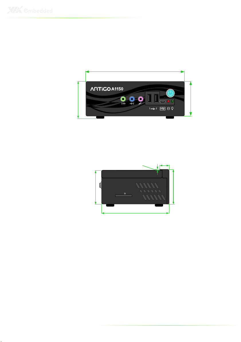
50 mm
52 mm
2.01 mm
14 mm
99 mm
ARTIGO-A1150 DIMENSIONS
146 mm
56 mm
Inspired by Pico-ITX
5
52 mm
7
Page 16

8
Page 17

2
Front, Rear and Side
I/O Pin Descriptions
and Functionality
9
Page 18
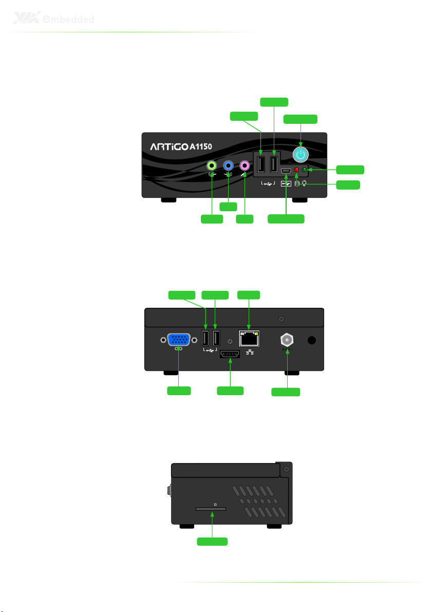
HDMI
DC IN 12V
Power port
VGA port
USB port 4
USB port 3
LAN port
HDMI port
SD
SD Card slot
FRONT I/O LAYOUT
USB port 1
USB port 2
Power button
Inspired by Pico-ITX
5
Line-out
Line-in
Mic-in
REAR I/O LAYOUT
SIDE I/O LAYOUT
Mini USB port
Power LED
HDD LED
10
Page 19
I/O PIN DESCRIPTION
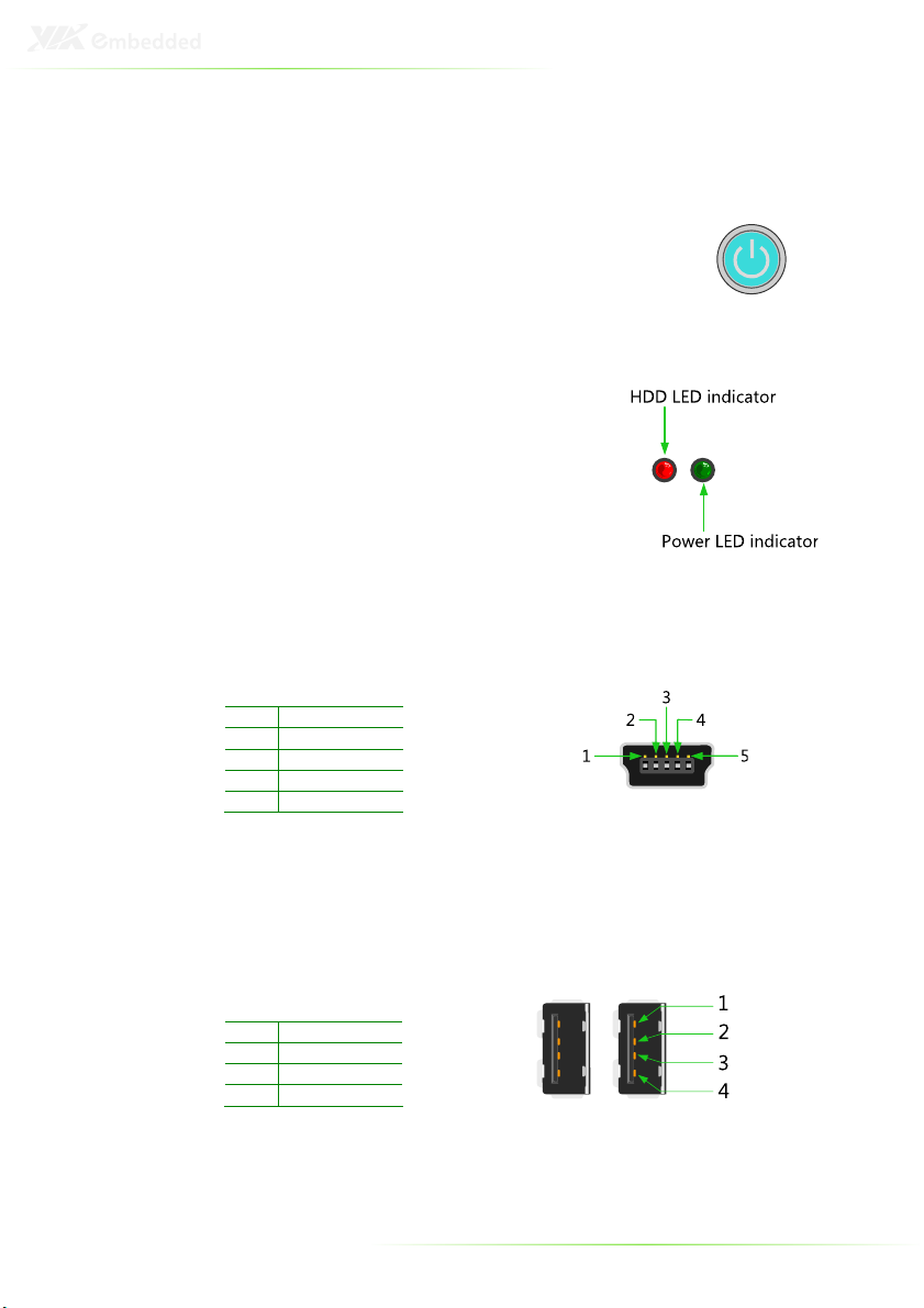
Power Button
The ARTiGO-A1150 comes with a Power On/Off
button, that supports Soft Power-On/Off (Instant
Off or 4-Second Delay) and Suspend.
LED Indicators (Power LED and HDD LED)
There are two LEDs on the front face
plate that indicate the system status: The
Power LED indicates the power status
and flashes in green. The HDD LED
indicates the hard disk status and flashes
in red.
USB device port
The ARTiGO-A1150 provides a USB device port in the front panel for
quick data transfer to another computer.
Pin Signal
1 +5VUSBD
2 USBDP3 USBDP+
4 USBID
5 GND
USB 2.0 ports
The ARTiGO-A1150 provides four USB 2.0 ports (two in the front
panel, and two in the rear panel) for Plug & Play and hot
swapping access to external devices. The USB interface complies
with USB UHCI, Rev. 2.0.
Pin Signal
1 VCC
2 USB_P03 USB_P0+
4 GND
11
Page 20
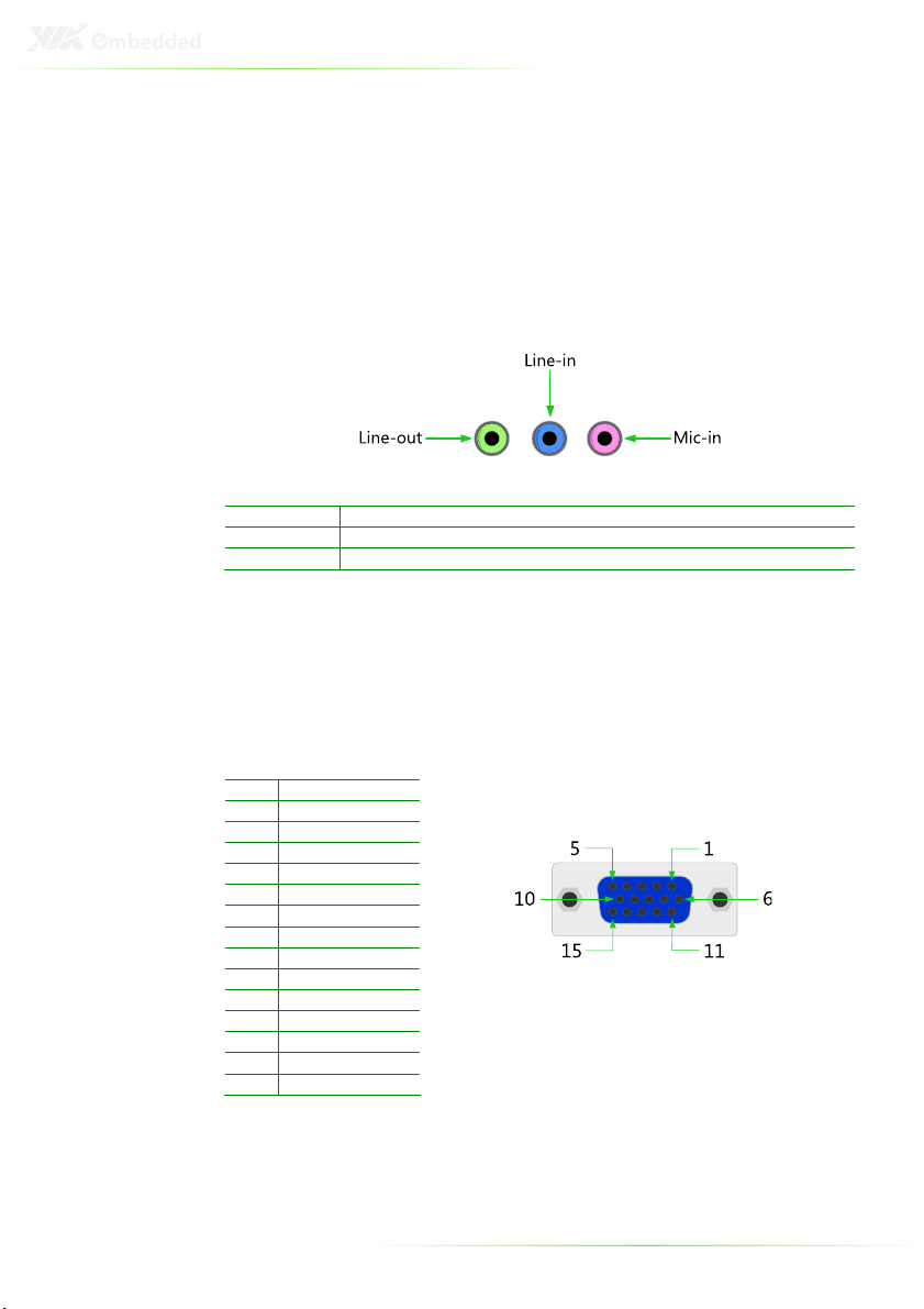
Audio Ports (Line-out, Line-in and Mic-in)
The ARTiGO-A1150 offers High Definition Audio through three
3.5 mm TRS jack connectors: Line-out, Line-in and Mic-in.
The Line-out jack is for connecting to external speakers or
headphones. The Line-In jack is for connecting to an external audio
device such as a CD player, tape player, etc. The Mic-in jack is for
connecting to a microphone.
Connector
Line-out Phone Jack 3.5Ø 5P, 90 Degree, Female, color lime green, SHIELDED
Line-in Phone Jack 3.5Ø 5P, 90 Degree, Female, color light blue, SHIELDED
Mic-in Phone Jack 3.5Ø 5P, 90 Degree, Female, color light pink, SHIELDED
Type
VGA Port
The ARTiGO-A1150 provides a high resolution VGA interface
through a 15-pin D-sub female connector to support analog VGA
CRT monitors. It supports VGA and VESA, up to 1920 x 1200 @
60Hz resolution and up to 256 MB shared memory.
Pin Signal
1 Red
2 Green
3 Blue
4 NC
5 GND
6 GND
7 GND
8 GND
9 NC
10 GND
11 NC
12 DDC DAT
13 H-SYNC
14 V-SYNC
15 DDC CLK
12
Page 21
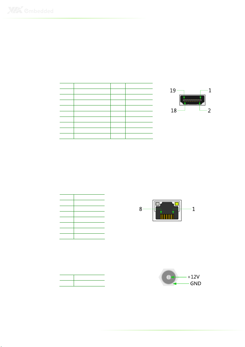
HDMI® Port
The ARTiGO-A1150 provides a High Definition Multimedia
Interface port for connecting to high definition video and digital
audio. The HDMI® port connector allows you to connect digital
video devices which utilize a high definition video signal.
Pin Signal Pin Signal
1 TX2+ 2 GND
3 TX2- 4 TX1+
5 GND 6 TX17 TX0+ 8 GND
9 TX0- 10 TXC+
11 GND 12 TXC13 - 14 15 DDCSCL 16 DDCSDA
17 GND 18 +5V
19 Hot Plug Detect
LAN Port
The ARTiGO-A1150 is equipped with the VIA VT6122 Gigabit LAN
controller. The Ethernet port provides a standard RJ-45 jack
connector with LED indicators to show its Active/Link status
(green LED) and Speed status (white LED).
Pin Signal
1 TXPA
2 TXNA
3 TXPB
4 TXNB
5 TXPC
6 TXNC
7 TXPD
8 TXND
Power Input (DC-In) Port
The ARTiGO-A1150 comes with a DC Power Input connector jack.
Pin Signal
1 GND
2 +12V
13
Page 22

14
Page 23

3
Basic installation
15
Page 24

INSTALLING THE MEMORY
Step 1
Step 1
Step 1Step 1
Locate the memory access cover on the bottom side of the
ARTiGO-A1150 and remove the screw.
Step 2
Step 2
Step 2Step 2
Remove the memory access cover as indicated in the figure below.
16
Page 25

Step 3
Step 3
Step 3Step 3
Insert the memory module into the DDR3 SODIMM socket at the
45 degree angle. Then push down until the memory module
snaps into place. The DDR3 SODIMM socket has two locking
mechanisms that will click once the memory module has been
fully inserted.
1 2
Step
Step 4444
Step Step
Reinstall the memory access cover and secure it with screw.
17
Page 26

OPENING THE TOP COVER CHASSIS
Step 1
Step 1
Step 1Step 1
Remove the screw of the top cover from the rear panel of the
ARTiGO-A1150.
Step 2
Step 2
Step 2Step 2
Then gently slide the top cover backward and lift off the top cover
as indicated in the figure below.
18
Page 27

INSTALLING THE SATA 2.5” HARD DISK
Step 1
Step 1
Step 1Step 1
Gently slide and remove the top cover backward and lift off the
top cover.
Step
Step 2222
Step Step
On the bottom side of the top cover, remove the SATA 2.5” hard
disk cover plate by unscrewing the four screws.
19
Page 28

Step
Step 3333
Step Step
Attach the hard disk plate to the 2.5-inch SATA hard disk by
aligning the mounting holes on the SATA 2.5” hard disk with the
mounting holes on the hard disk cover plate. Then secure the
hard disk in place with four screws.
Step
Step 4444
Step Step
On the bottom side of the top cover, remove the protective
(plastic) layer of the hard disk thermal pad.
20
Page 29

Step
Step 5555
Step Step
Reinstall the hard disk plate by aligning the cover plate with the
mounting holes under the top cover and secure it with four
screws.
Step
Step 6666
Step Step
Connect the SATA power and SATA data cables to the hard disk.
21
Page 30

Step
Step 7777
Step Step
Replace the top cover onto the ARTiGO-A1150.
22
Page 31

INSTALLING THE SD CARD READER
Step 1
Step 1
Step 1Step 1
Locate the mounting area of SD card reader. Remove the five
screws in order to remove the front panel plate.
SSSStep 2
tep 2
tep 2tep 2
Remove the fan duct as indicated in the figure below.
23
Page 32

1
1
Step 3
Step 3
Step 3Step 3
Mount the SD card reader module (EMIO-5130) and secure it with
two screws.
Step 4
Step 4
Step 4Step 4
Locate the SD card reader pin headers on the SD card reader
module (EMIO-5130) and on the P820-B daughter card.
24
Page 33

Step 5
Step 5
Step 5Step 5
Gently connect the SD card reader cable to the pin header on the
SD card reader module (EMIO-5130) and to the pin header on the
P820-B daughter card.
1
1
1
1
25
Page 34

Step
Step 6666
Step Step
Properly route the SD card reader cable underneath the fan duct.
Then reinstall the fan duct and front panel plate.
1
2
Step
Step 7777
Step Step
Replace the top cover of the ARTiGO-A1150.
26
Page 35

INSTALLING THE WLAN KIT
Step 1
Step 1
Step 1Step 1
Remove the top cover and the front panel plate by unscrewing
the five screws as indicated in the figure below.
Ste
Step 2
p 2
SteSte
p 2p 2
Remove the four screws indicated by the red arrows and carefully
lift the fan duct off the board.
27
Page 36

Step 3
Step 3
Step 3Step 3
Locate the WLAN pin header on the P820-B daughter card.
Step 4
Step 4
Step 4Step 4
Gently connect WLAN USB cable to the pin header on the P820-B
daughter card.
28
Page 37

3
1
2
Step 5
Step 5
Step 5Step 5
First reinstall the fan duct, and connect the grounding cable to one
of the screws of the fan duct as indicated in the figure below. Then
attach the front panel plate and secure it with screws.
Note:
Make sure the WLAN USB cable is properly routed underneath
the fan duct.
Step
Step 6666
Step Step
Locate the WLAN antenna hole at the rear side of the chassis and
install the WLAN antenna.
29
Page 38

Step
Step 7777
Step Step
Mount the WLAN USB module (EMIO-1530 802.11b/g or EMIO1533 802.11n) on the bottom side of chassis top cover with two
screws.
Step
Step 8888
Step Step
Connect the WLAN USB cable to the mini connector on the WLAN
module and the grounding cable to the screw area. Then connect
the WLAN antenna cable to the micro RF connector on the WLAN
USB module (EMIO-1530 802.11b/g or EMIO-1533 802.11n) as
indicated in the figure below.
Step
Step 9999
Step Step
Reinstall the top cover of the ARTiGO-A1150.
30
Page 39

INSTALLING VESA MOUNT BRACKET
An optional VESA mount bracket kit is available for mounting the
ARTiGO-A1150 behind the monitor.
Step
Step 1111
Step Step
Attach the VESA mount bracket to the back of the monitor as
indicated in the figure.
31
Page 40

Step
Step 2222
Step Step
Place the ARTiGO-A1150 unit into the VESA mount bracket. Then
connect all the necessary cables from the opening in the base of
the bracket.
32
Page 41

4
BIOS Setup
This chapter gives a detailed explanation of the BIOS setup
functions.
33
Page 42

ENTERING THE BIOS SETUP MENU
Power on the computer and press <Delete
of the boot sequence to enter the BIOS setup menu. If you missed
the BIOS setup entry point, restart the system and try again.
Delete> during the beginning
DeleteDelete
CONTROL KEYS
Keys Description
Up Move to the previous item
Down Move to the next item
Left Move to the previous tab
Right Move to the next tab
Enter Select the item
Esc Jumps to the Exit menu or returns to the main menu
+ (number pad) Increase the numeric value
- (number pad) Decrease the numeric value
F1 General help, only for Status Page Setup Menu and
F7 Discard Changes
F9 Load Optimized defaults
F10 Save all the changes and exit
from a submenu
Option Page Setup Menu
34
Page 43

GETTING HELP
The BIOS setup program provides a “General Help
can display this screen from any menu/sub-menu by pressing
<F1
F1>. The help screen displays the keys for using and navigating
F1F1
the BIOS setup. Press <Esc
Esc> to exit the help screen.
EscEsc
General Help” screen. You
General HelpGeneral Help
35
Page 44

System Time [1 : 42 : 06]
System Overview
Version : 1.01
Use [ENTER], [TAB] or
[SHIFT-TAB] to select
a field.
Use [+] or [-] to
configure system time.
System Date [Thu 09/29/2011]
AMIBIOS
Build Date : 09/21/11
ID : H310S101
VIA Eden X2 U4100 @ 800 MHz
Processor
Size : 1792MB
System Memory
BIOS SETUP UTILITY
V02.69 (C) Copyright 1985-2010, American Megatrends, Inc.
+ Tab
F1
F10
ESC
Select Screen
Select Item
Change Option
Select Field
General Help
Save and Exit
Exit
Main Advanced Boot Security Exit
SYSTEM OVERVIEW
The System Overview screen is the default screen that is shown
when the BIOS Setup Utility is launched. This screen can be
accessed by traversing the navigation bar to the “Main” label.
AMIBIOS
The content in this section of the screen shows the current BIOS
version, build date, and ID number.
Processor
This content in this section shows the CPU information that has
been detected. This information includes the CPU name and
speed.
System Memory
This section shows the amount of available memory that has been
detected.
System Time
This section shows the current system time. Press Tab
right and Shift+Tab
second segments. The ++++ and ---- keys on the number pad can be
used to change the values. The time format is [Hour : Minute :
Second].
Shift+Tab to traverse left through the hour, minute, and
Shift+TabShift+Tab
Tab to traverse
TabTab
36
Page 45

System Date
This section shows the current system date. Press Tab
right and Shift+Tab
year segments. The ++++ and ---- keys on the number pad can be used
to change the values. The weekday name is automatically
updated when the date is altered. The date format is [Weekday,
Month, Day, Year].
Shift+Tab to traverse left through the month, day, and
Shift+TabShift+Tab
Tab to traverse
TabTab
37
Page 46

ADVANCED SETTINGS
The Advanced Settings screen shows a list of categories that can
provide access to a sub-screen. Sub-screen links can be identified
by the preceding right-facing arrowhead.
Main Advanced Boot Security Exit
Advanced Settings
WARNING :
Setting wrong values in below sections
may cause system to malfunction.
CPU Configuration
SATA Configuration
SuperIO Configuration
Hardware Health Configuration
ACPI Configuration
APM Configuration
Spread Spectrum Configuration
USB Configuration
CRB Configuration
BIOS SETUP UTILITY
Configure CPU.
Select Screen
Select Item
Enter
Go to Sub Screen
F1
General Help
F10
Save and Exit
ESC
Exit
V02.69 (C) Copyright 1985-2010, American Megatrends, Inc.
The Advanced Settings screen contains the following links:
CPU Configuration
SATA Configuration
SuperIO Configuration
Hardware Health Configuration
ACPI Configuration
APM Configuration
Spread Spectrum Configuration
USB Configuration
CRB Configuration
38
Page 47

CPU CONFIGURATION
The CPU Configuration screen shows detailed information about
the built-in processor. In addition to the processor information, the
thermal controls can be set.
Advanced
Configure advanced CPU settings
Module Version 01.08
Manufacturer : VIA
VIA Eden X2 U4100 @ 800 MHz
Speed (FSB 133MHz * 6): 800MHz
Core : 2
Cache L1 : 128 KB
Cache L2 : 1024 KB
Microcode revision : 24
Nano CPU TM3 Function [Enabled]
BIOS SETUP UTILITY
Enabled/Disabled
Nano CPU Thermal
Monitor 3 function.
Select Screen
Select Item
+ -
Change Option
F1
General Help
F10
Save and Exit
ESC
Exit
V02.69 (C) Copyright 1985-2010, American Megatrends, Inc.
Nano CPU TM3 Function
The Nano CPU TM3 Function has two settings: Disabled and
Enabled. When the setting is changed to “Disabled”, the CPU’s
built-in thermal sensor will not function. When the setting is
changed to “Enabled”, the thermal sensor will automatically adjust
the CPU ratio and V
to prevent the CPU from overheating.
CORE
39
Page 48

SATA CONFIGURATION
The SATA Configuration screen shows links to the primary and
secondary SATA hard drive information screens.
Advanced
SATA Configuration
Serial ATA IDE devices
SATA-1 Primary IDE : [Hard Disk]
SATA-1 Secondary IDE : [Not Detected]
BIOS SETUP UTILITY
While entering setup,
BIOS auto detects the
presence of SATA devices.
This displays the status
of auto detection of SATA
devices.
Select Screen
Select Item
Enter
Go to Sub Screen
F1
General Help
F10
Save and Exit
ESC
Exit
V02.69 (C) Copyright 1985-2010, American Megatrends, Inc.
The SATA Configuration screen contains the following links:
SATA-I Primary IDE
SATA-I Secondary IDE
Hard Disk Information
When a hard drive is detected, the hard drive’s detailed
information can be displayed on the SATA-1 Primary/Secondary
IDE sub-screen.
Advanced
SATA-1 Primary IDE
Device : Not Detected
PIO Mode : Auto
DMA Mode : Auto
V02.69 (C) Copyright 1985-2010, American Megatrends, Inc.
BIOS SETUP UTILITY
Select the type of
Select PIO Mode.
device connected to the
system.
Select Screen
Select Item
+ -
Change Option
F1
General Help
F10
Save and Exit
ESC
Exit
40
Page 49

In addition, the PIO and DMA modes may be configured for each
SATA hard drive.
PIO Mode
The PIO Mode has six possible settings: Auto, 0, 1, 2, 3, and 4. The
“Auto” setting enables the BIOS to autonomously determine the
appropriate PIO mode for the hard drive. If a manual setting is
preferred, then be sure the correct PIO mode of the hard drive is
used. It is not recommended to set the PIO mode higher than
what the hard drive manufacturer states.
DMA Mode
The DMA Mode has four possible settings: Auto, SWDMAn,
MWDMAn and UDMAn. If a manual setting is preferred, then be
sure the correct DMA mode of the hard drive is used.
Auto
Auto
AutoAuto
The “Auto” setting enables the BIOS to automatically detect DMA
mode.
SWDMAn
SWDMAn
SWDMAnSWDMAn
Single Word DMA mode.
MWDMAn
MWDMAn
MWDMAnMWDMAn
Multi Word DMA mode.
UDMAn
UDMAn
UDMAnUDMAn
Ultra Word DMA mode.
41
Page 50

SUPERIO CONFIGURATION
The SuperIO Configuration screen shows the specific addresses
and IRQs of the onboard serial ports.
Advanced
Configure F81865F Super IO Chipset
Serial Port1 Address [3F8/IRQ4]
Serial Port2 Address [2F8/IRQ3]
BIOS SETUP UTILITY
Allows BIOS to select
Serial Port1 base
addresses.
Select Screen
Select Item
+ -
Change Option
F1
General Help
F10
Save and Exit
ESC
Exit
V02.69 (C) Copyright 1985-2010, American Megatrends, Inc.
Serial Ports 1 to 2 Address
This option allows the user to select the Serial Port 1 and 2 base
I/O address and interrupt request address. The Serial Port 1 to 2
has four selectable options.
Port Address and IRQs
1 Disabled, 3F8/IRQ4, 3E8/IRQ4, 2E8/IRQ3
2 Disabled, 3F8/IRQ4, 2F8/IRQ3, 2E8/IRQ3
42
Page 51

Hardware Health Configuration
Fan configuration mode
setting
System Temperature :28°C/82°F
+1.2V (VIN1) :1.240 V
Advanced
CPU Temperature :33°C/91°F
Fan1 Speed :3000 RPM
+3.3V (VIN2) :3.352 V
Smart FAN 1 :[Auto]
BIOS SETUP UTILITY
V02.69 (C) Copyright 1985-2010, American Megatrends, Inc.
+ F1
F10
ESC
Select Screen
Select Item
Change Option
General Help
Save and Exit
Exit
HARDWARE HEALTH CONFIGURATION
The Hardware Health Configuration displays all monitored
information. The temperature is taken from a sensor.
Smart FAN 1
The Smart FAN features have two options: Auto and Full Speed.
The “Auto” option enables the BIOS to adjust the fan speed
according to the needs of the CPU and system. The “Full Speed”
option forces the fans to run at their maximum RPM.
43
Page 52

ACPI CONFIGURATION
Advanced Configuration and Power Interface (ACPI) grants the
operating system direct control over system power management.
The ACPI Configuration screen can be used to set a number of
power management related functions.
Advanced
ACPI Settings
Suspend mode [Auto]
ACPI Version Features [ACPI v3.0]
BIOS SETUP UTILITY
Select the ACPI state used
for System Suspend
Select Screen
Select Item
+ -
Change Option
F1
General Help
F10
Save and Exit
ESC
Exit
V02.69 (C) Copyright 1985-2010, American Megatrends, Inc.
Suspend Mode
The Suspend Mode field has three selectable options.
S1
S1 (POS)
(POS)
S1S1
(POS)(POS)
S1/Power On Suspend (POS) is a low power state. In this state, no
system context (CPU or chipset) is lost and hardware maintains all
system contexts.
S3
S3 (STR)
(STR)
S3S3
(STR)(STR)
S3/Suspend To RAM (STR) is a power-down state. In this state,
power is supplied only to essential components such as main
memory and wakeup-capable devices. The system context is saved
to main memory, and context is restored from the memory when
a "wakeup" event occurs.
Auto
Auto
AutoAuto
When the Suspend Mode is set to Auto, the operating system will
control the power state.
ACPI Version Features
The ACPI Version Features enables the BIOS to support the
designated ACPI specification. There are three versions to choose
from: ACPI 1.0, ACPI 2.0, and ACPI 3.0.
44
Page 53

APM CONFIGURATION
Advanced Power Management (APM) enables the operating
system to co-work with the BIOS to control the system power
management. The APM Configuration screen can be used to set a
number of power management functions.
Advanced
Power Button Mode [On/Off]
Restore on AC/Power Loss [Last State]
Advanced Resume Event Controls
Resume On LAN [Disabled]
Resume On RTC Alarm [Disabled]
BIOS SETUP UTILITY
On/Off
Standby
Suspend
+ F1
F10
ESC
Options
Select Screen
Select Item
Change Option
General Help
Save and Exit
Exit
V02.69 (C) Copyright 1985-2010, American Megatrends, Inc.
Power Button Mode
The Power Button Mode has three options.
On/Off
On/Off
On/OffOn/Off
When On/Off is selected, pressing the power button will instantly
cause the system to power on or off.
Standby
Standby
StandbyStandby
When Standby is selected; the power button must be pressed and
held down for 4 seconds before the system will power off.
Suspend
Suspend
SuspendSuspend
When Suspend is selected, pressing the power button will
instantly cause the system to enter suspend mode.
45
Page 54

Restore on AC/Power Loss
Restore on AC/Power Loss defines how the system will respond
after AC power has been interrupted while the system is on. There
are three options.
Power Off
Power Off
Power OffPower Off
The Power Off option keeps the system in an off state until the
power button is pressed again.
Power On
Power On
Power OnPower On
The Power On option restarts the system when the power has
returned.
Last State
Last State
Last StateLast State
The Last State option restores the system to its previous state when
the power was interrupted.
Resume on LAN
Resume on LAN allows to turned on a system that has been put
into suspend or standby mode. When this feature is enabled, LAN
activity as defined in the Resume on LAN
system to wake up. This feature has three options.
SSSS1111
The S1 option enables LAN activity to be detected if the system is
in S1 power saving mode.
Resume on LAN feature will cause the
Resume on LANResume on LAN
S1/
S1/S3/S4/S5
S3/S4/S5
S1/S1/
S3/S4/S5S3/S4/S5
The S1/S3/S4/S5 option enables LAN activity to be detected if the
system is in S1/S3/S4/S5 power saving mode.
Disabled
Disabled
DisabledDisabled
The Disabled option disables the detection of all LAN activity.
Resume on RTC Alarm
Resume on RTC Alarm can only be used if Resume on Software
RTC Alarm
RTC Alarm is not enabled. This feature enables the BIOS to
RTC AlarmRTC Alarm
automatically power on the system at a scheduled time. When
enabled, the RTC Alarm Date
unlocked.
RTC Alarm Date and System Time
RTC Alarm DateRTC Alarm Date
System Time features will be
System TimeSystem Time
Resume on Software
Resume on Software Resume on Software
46
Page 55

RTC Alarm Date (Days)
The RTC Alarm Date feature is visible only when Resume on RTC
Alarm
Alarm is enabled. This feature enables the user to specify a specific
AlarmAlarm
date each month or daily recurrence. Use the ++++ and ---- keys on the
number pad to change the value of the RTC Alarm Date.
Every Day
Every Day
Every DayEvery Day
The Every Day option triggers the RTC Alarm daily.
1
1 –––– 31
31
1 1
31 31
When a specific numeric date is selected, the RTC Alarm will be
triggered on that day of the month.
Resume on RTC
Resume on RTC Resume on RTC
System Time
The System Time option enables the user to specify the time the
system should power on for the date that is set in RTC Alarm Date
RTC Alarm Date.
RTC Alarm DateRTC Alarm Date
47
Page 56

Spread Spectrum Configuration
Dynamic to adjust SSC.
CPU Spread Spectrum Setting [0.1%]
Advanced
BIOS SETUP UTILITY
V02.69 (C) Copyright 1985-2010, American Megatrends, Inc.
+ F1
F10
ESC
Select Screen
Select Item
Change Option
General Help
Save and Exit
Exit
SPREAD SPECTRUM CONFIGURATION
The Spread Spectrum Configuration screen enables access to the
Spread Spectrum Setting feature.
CPU Spread Spectrum Setting
The Spread Spectrum Setting feature enables the BIOS to
modulate the clock frequencies originating from the mainboard.
The settings are in percentages of modulation. Higher
percentages result in greater modulation of clock frequencies. This
feature has settings that range from 0.1% to 0.9%.
48
Page 57

USB CONFIGURATION
The USB Configuration screen shows the number of connected
USB devices. Additionally, support for various USB features can be
enabled or disabled.
Advanced
USB Configuration
Module Version - 2.24.5-13.4
USB Devices Enabled :
1 Keyboard, 1 Mouse
USB Device Mode Enable [Enabled]
USB Endpoint0 Ctrl Clk [Enabled]
USBD Interface Selection [Original]
BIOS SETUP UTILITY
Enables USB device mode.
Select Screen
Select Item
+ -
Change Option
F1
General Help
F10
Save and Exit
ESC
Exit
V02.69 (C) Copyright 1985-2010, American Megatrends, Inc.
USB Device Mode Enable
Settings Description
Enabled Unlocks the USB device port.
Disabled Locks the USB device port.
USB Endpoint0 Ctrl Clk
This option is only available if USB Device Mode Enable
Settings Description
Enabled Enable dynamic clock control
Disabled Disable dynamic clock control
USB Device Mode Enable is enabled.
USB Device Mode EnableUSB Device Mode Enable
USBD Interface Selection
This option is only available if USB Device Mode Enable
Settings Description
Register Out Select register out CCA interface
Original Select original CCA interface
USB Device Mode Enable is enabled.
USB Device Mode EnableUSB Device Mode Enable
49
Page 58

CRB CONFIGURATION
The CRB Configuration screen includes several chipset settings.
Advanced
DRAM Clock [Auto]
Select Display Device 1 [CRT]
Select Display Device 2 [HDMI]
VGA Share Memory (Frame Buffer) [256MB]
OnChip HDAC Device [Enable]
WATCH-DOG [Disabled]
VT6130 LAN Control [Enabled]
LAN Option ROM [Disabled]
BIOS SETUP UTILITY
Auto
400 MHz
533 MHz
+ F1
F10
ESC
Options
Select Screen
Select Item
Change Option
General Help
Save and Exit
Exit
V02.69 (C) Copyright 1985-2010, American Megatrends, Inc.
DRAM Clock
The DRAM Clock feature enables the user to determine how the
BIOS handles the memory clock frequency. The memory clock can
either be dynamic or static. This feature has three options.
Auto
Auto
AutoAuto
The Auto option enables the BIOS to select a compatible clock
frequency for the installed memory.
400 MHz
400 MHz
400 MHz400 MHz
The 400 MHz option forces the BIOS to be fixed at 800 MHz for
DDR3 memory modules.
533 MHz
533 MHz
533 MHz533 MHz
The 533 MHz option forces the BIOS to be fixed at 1066 MHz for
DDR3 memory modules.
Select Display Device 1 and 2
The Select Display Device feature enables the user to choose a
specific display interface. This feature has twelve options: CRT, LCD
and HDMI®.
50
Page 59

VGA Share Memory (Frame Buffer)
The VGA Share Memory feature enables the user to choose the
amount of the system memory to reserve for use by the integrated
graphics controller. The amount of memory that can be reserved
ranges from 64 – 512 MB.
OnChip HDAC Device
The OnChip HDAC Device feature enables the BIOS to control the
high definition audio codec in the chipset. This feature has two
options: enable and disable.
WATCH-DOG
The WATCHDOG Timer Enable feature unlocks two other features
that enable the BIOS to monitor the state of the system. This
feature has two options: enabled or disabled.
VT6130 LAN Control
The VT6130 LAN Control feature determines whether the
onboard LAN controller will be used or not.
LAN Option ROM
The LAN Option ROM feature will only be visible if the VT6130
LAN Control
LAN Control feature is enabled. If the LAN Option ROM feature is
LAN ControlLAN Control
enabled, then the system will load a separate ROM for the LAN
controller in order to boot through the Gigabit Ethernet.
VT6130
VT6130 VT6130
51
Page 60

Boot Settings
Configure Settings
during System Boot.
Boot Settings Configuration
Boot Device Priority
BIOS SETUP UTILITY
V02.69 (C) Copyright 1985-2010, American Megatrends, Inc.
Enter
F1
F10
ESC
Select Screen
Select Item
Go to Sub Screen
General Help
Save and Exit
Exit
Main Advanced Boot Security Exit
Boot
Boot Settings Configuration
Allows BIOS to skip
certain tests while
booting. This will
decrease the time needed
to boot the system.
Quick Boot [Enabled]
Quiet Boot [Enabled]
Bootup Num-Lock [On]
Wait for 'F1' if Error [Enabled]
Hit 'DEL' Message Display [Enabled]
BIOS SETUP UTILITY
V02.69 (C) Copyright 1985-2010, American Megatrends, Inc.
+ F1
F10
ESC
Select Screen
Select Item
Change Option
General Help
Save and Exit
Exit
BOOT SETTINGS
The Boot Settings screen has a single link that goes to the Boot
Settings Configuration
Settings Configuration and Boot Device Priority
Settings ConfigurationSettings Configuration
Boot Device Priority screens.
Boot Device PriorityBoot Device Priority
Boot Settings Configuration
Boot Device Priority
Boot Settings Configuration
The Boot Settings Configuration screen has several features that
can be run during the system boot sequence.
Boot
Boot Boot
52
Page 61

Quick Boot
The Quick Boot feature enables the BIOS to skip certain tests in
order to speed up the boot sequence. This feature has two
options: enabled and disabled.
Quiet Boot
The Quiet Boot feature hides all of the Power-on Self Test (POST)
messages during the boot sequence. Instead of the POST
messages, the user will see an OEM logo. This feature has two
options: enabled and disabled.
Bootup Num-Lock
The Bootup Num-Lock feature determines how the 10-key pad
will behave. When the feature is enabled, the 10-key pad will
behave as a number pad. When the feature is disabled, the 10-key
pad will behave as cursor navigation keys.
Wait for ‘F1’ if Error
This feature determines how the system will respond if an error is
detected during the boot sequence. If this feature is enabled, the
BIOS will pause booting and wait for the user to press F1 to enter
the BIOS setup menu. This feature has two options: enabled and
disabled.
Hit ‘DEL’ Message Display
This feature determines if the BIOS will display a POST message
that informs the user how to access the BIOS Setup Utility.1 This
feature has two options: enabled and disabled.
53
Page 62

Boot Device Priority
Specifies the best
sequence from the
available devices.
A device enclosed in
parenthesis has been
disabled in the
corresponding type menu.
1st Boot Device [Network: VIA Networking]
Boot
BIOS SETUP UTILITY
V02.69 (C) Copyright 1985-2010, American Megatrends, Inc.
+ F1
F10
ESC
Select Screen
Select Item
Change Option
General Help
Save and Exit
Exit
BOOT DEVICE PRIORITY
The Boot Device Priority screen lists all bootable devices.
1st Boot Device
This feature specifies the boot sequence from the available devices.
The available boot devices are detected dynamically and bootable
devices will be listed accordingly. This feature has two options:
Network: VIA Networking Bootagent, and Disabled]
54
Page 63

SECURITY SETTINGS
The Security Settings screen provides a way to restrict access to the
BIOS or even the entire system.
Main Advanced Boot Security Exit
Security Settings
Supervisor Password : Not Installed
User Password : Not Installed
Change Supervisor Password
Change User Password
BIOS SETUP UTILITY
Install or Change the
password.
Select Screen
Select Item
Change
Enter
General Help
F1
F10
Save and Exit
ESC
Exit
V02.69 (C) Copyright 1985-2010, American Megatrends, Inc.
Change Supervisor Password
This option is for setting a password for accessing the BIOS setup
utility. When a password has been set, a password prompt will be
displayed whenever the BIOS setup utility is launched. This
prevents an unauthorized person from changing any part of the
system configuration.
When a supervisor password is set, the Pas
Password Check
sword Check option
PasPas
sword Checksword Check
will be unlocked.
Change User Password
This option is for setting a password for non-supervisors. When a
user password is set, the Clear User Password and Password
Check options will be unlocked.
Clear User Password
This option is only available when the user accesses the BIOS
Setup Utility when the user password has been specified.
55
Page 64

Password Check
This feature is compulsory when the Change Supervisor Password
option is set. The user will have up to three chances to enter the
correct password before the BIOS forces the system to stop
booting. If the user does not enter the correct password, the
keyboard will also lock up. The only way to get past this is to do a
hard reboot (i.e., use the system reset button or cut off the power
to the system). A soft reboot (i.e., Ctrl+Alt+Del) will not work
because the keyboard will be locked. This feature has two options.
Setup
Setup
SetupSetup
The Setup option forces user to enter a password in order to
access the BIOS Setup Utility.
Always
Always
AlwaysAlways
The Always option forces users to enter a password in order to
boot up the system.
Change Supervisor Password
Change Supervisor PasswordChange Supervisor Password
56
Page 65

EXIT OPTIONS
Main Advanced Boot Security Exit
Exit Options
Save Changes and Exit
Discard Changes and Exit
Discard Changes
Load Optimal Defaults
BIOS SETUP UTILITY
Exit system setup after
saving the changes.
F10 key can be used for
this operation.
Select Screen
Select Item
Enter
Change
F1
General Help
F10
Save and Exit
ESC
Exit
V02.69 (C) Copyright 1985-2010, American Megatrends, Inc.
Save Changes and Exit
Save all changes to the BIOS and exit the BIOS Setup Utility. The
“F10” hotkey can also be used to trigger this command.
Discard Changes and Exit
Exit the BIOS Setup Utility without saving any changes. The “Esc”
hotkey can also be used to trigger this command.
Discard Changes
This command reverts all changes to the settings that were in
place when the BIOS Setup Utility was launched. The “F7” hotkey
can also be used to trigger this command.
Load Optimal Defaults
Load optimal default values for all the setup items. The default
optimized values are defined by the mainboard manufacturer to
provide optimized environment for a basic system. The “F9” hotkey
can also be used to trigger this command.
57
Page 66

Page 67

5
Driver Installation
59
Page 68

MICROSOFT DRIVER SUPPORT
The VIA ARTiGO-A1150 is compatible with Microsoft operating
systems. The latest Windows drivers can be downloaded from the
VEPD website at www.viaembedded.com.
For embedded operating systems, the related drivers can be
found in the VIA Embedded website at www.viaembedded.com.
LINUX DRIVER SUPPORT
The VIA ARTiGO-A1150 is highly compatible with many Linux
distributions.
Support and drivers are provided through various methods
including:
1. Drivers provided by VIA
2. Using a driver built into a distribution package
3. Visiting www.viaembedded.com for the latest updated
drivers
4. Installing a third party driver (such as the ALSA driver from
the Advanced Linux Sound Architecture project for
integrated audio)
For OEM clients and system integrators developing a product for
long term production, other code and resources may also be
made available. Contact VEPD to submit a request.
60
 Loading...