

Page 1
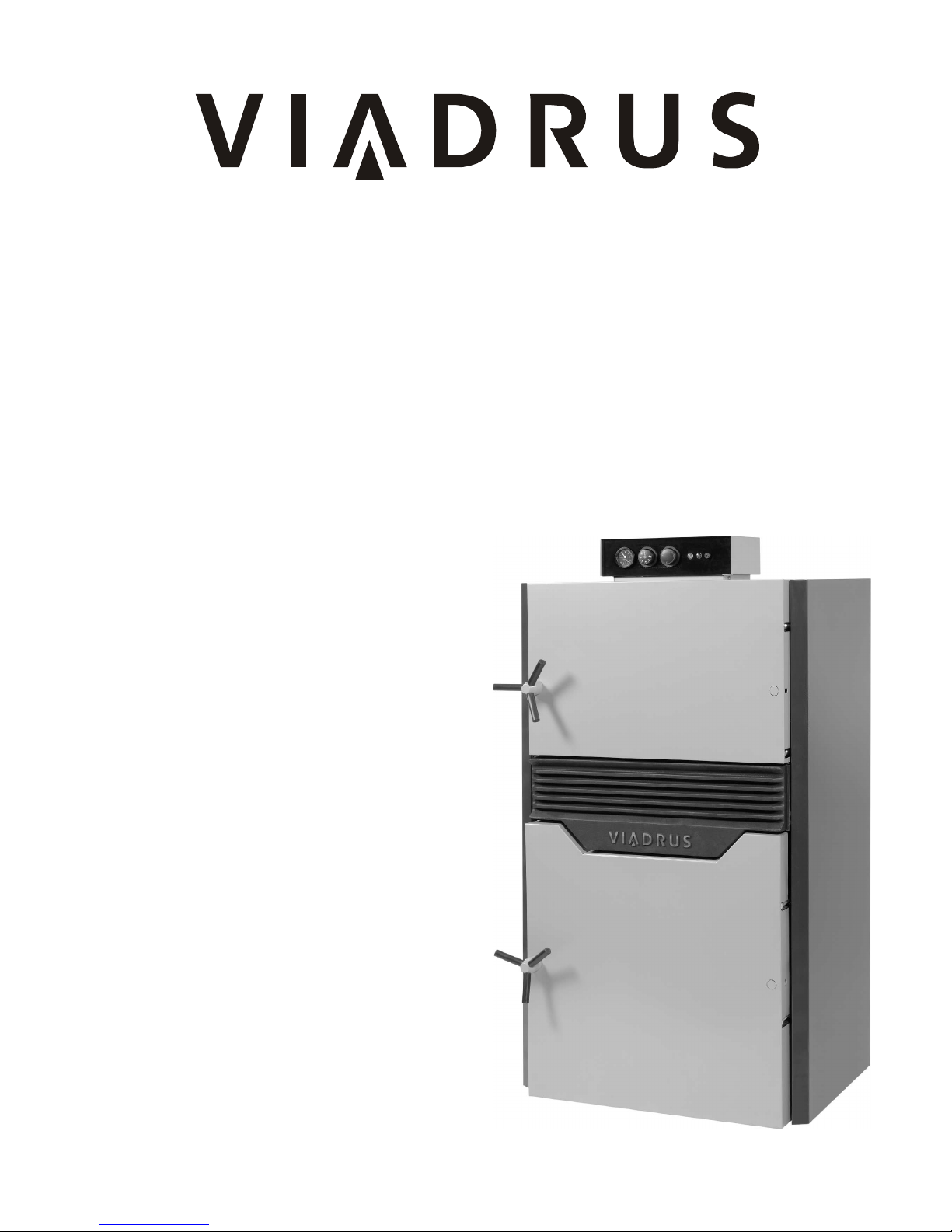
Hercules U26
Návod k obsluze
Hefaistos P 1
MANUAL FOR BOILER OPERATION
AND INSTALLATION
Page 2

Table of contents:
page
1.
Produced variants of boilers ................................................................................................................... 3
1.1 Order ................................................................................................................................................... 3
2.
Technical information .............................................................................................................................. 3
2.1 The use of boiler.................................................................................................................................. 3
2.2 Advantages of boiler ........................................................................................................................... 3
2.3 Technical data of boiler Hefaistos P1 ................................................................................................. 4
2.4 The main dimensions of the boiler ...................................................................................................... 5
2.4.1 The main dimensions of the boiler Hefaistos P1 T ...................................................................... 5
2.4.2 The main dimensions of the boiler Hefaistos P1 E ...................................................................... 6
2.5 The main parts of boiler ...................................................................................................................... 7
2.5.1 The main parts of boiler Hefaistos P1 T ...................................................................................... 7
2.5.2 The main parts of boiler Hefaistos P1 E ...................................................................................... 8
3.
Installation instructions ........................................................................................................................... 9
3.1 Boiler construction ............................................................................................................................... 9
3.2 Regulations and guidelines ............................................................................................................... 10
3.3 Placement options ............................................................................................................................. 11
3.4 Delivery and accessories .................................................................................................................. 13
3.4.1 Delivery and accessories - Hefaistos P1 T ................................................................................ 13
3.4.2 Delivery and accessories - Hefaistos P1 E ................................................................................ 13
3.5 Installation process............................................................................................................................ 14
3.5.1 Installing the boiler drum ............................................................................................................ 14
3.5.1.1 Installing the boiler drum – Hefaistos P1 T (see Fig. no. 8 and 9) ..................................... 14
3.5.1.2 Installing the boiler drum – Hefaistos P1 E (see Fig. no. 8 and 9) ..................................... 14
3.5.2 Mounting the control box ............................................................................................................ 18
3.5.2.1 Mounting the control box – Hefaistos P1 T (see Fig. no. 10) ............................................. 18
3.5.2.2 Mounting the control box – Hefaistos P1 E (see Fig. no. 10) ............................................. 18
3.5.3 Limit switch installation – Hefaistos P1 E .................................................................................. 20
3.5.4 Installation of cleaning tools ....................................................................................................... 20
4.
Commissioning ..................................................................................................................................... 21
4.1 Control activities before starting ........................................................................................................ 21
4.2 Putting the boiler into operation ........................................................................................................ 22
4.3 Regulatory and signaling elements ................................................................................................... 23
4.3.1 Regulatory and signaling elements – Hefaistos P1 T ................................................................ 23
4.3.2 Regulatory and signaling elements – Hefaistos P1 E ................................................................ 23
4.5 Equipment to remove excess heat .................................................................................................... 24
4.6 Equipment for heat removal - storage tanks ..................................................................................... 26
4.7 Diagram of connection-boiler Hefaistos P1 ....................................................................................... 26
4.8 Electrical connection ......................................................................................................................... 28
4.8.1 Electrical connection – Hefaistos P1 T ...................................................................................... 28
4.8.2 Electrical connection – Hefaistos P1 E ...................................................................................... 30
5.
Operating manual ................................................................................................................................. 32
5.1 Operation of boiler by user ................................................................................................................ 32
5.1.1 Operation of boiler by user – Hefaistos P1 T ............................................................................. 32
5.1.2 Operation of boiler by user – Hefaistos P1 E ............................................................................. 34
6.
Boiler cleaning - maintenance .............................................................................................................. 35
7.
Fault conditions ..................................................................................................................................... 37
8.
IMPORTANT NOTICES ........................................................................................................................ 38
9.
Instructions for disposal of the product after its life time....................................................................... 39
10. Warranty and liability for defects ........................................................................................................... 39
Page 3

3
Dear Customer,
Thank you for purchasing the pyrolytic boiler Hefaistos P1 and thus showing your confidence in the
company VIADRUS a.s.
Before you start to use your new product please read this manual (especially the chapter No. 5.1 Operation of boiler by user, and Chapter 8 – Important notices) so that from the beginning you get
used to its proper handling. Please respect the following information, thereby ensuring a long
trouble-free operation of your boiler to both your and our satisfaction.
1. Produced variants of boilers
1.1 Order
Following data must be specified in the order:
O
rder specification code
HEFAISTOS P1 X X
2. Technical information
Boiler Hefaistos P1 is a pyrolytic sectional cast-iron low pressure boiler with a metal sheet feed hopper
designed for burning the lump wood.
The control of boiler Hefaistos P1 T (thermostatic option) is solved by means of thermostats (in operation,
flue gases and pump -see chapter 4.3.1.).
Note: The thermostatic variant is used 6 – 7-sectional models.
The control of boiler Hefaistos P1 E (electronic version) is solved by means of controller ST 81.
Note: The electronic version is only applied to 3 – 5-sectional models.
The ventilator is equipped with a probe for speed sensing.
Combustion of other fuels and materials such as plastics is not permissible.
2.1 The use of boiler
Three-section model of boiler Hefaistos P1 is suitable for heating the family houses. Larger sizes of the
boiler meet the requirements of shops, schools, recreational facilities, weekend houses etc.
The boiler is manufactured as the hot water boiler with forced heating water circulation and working
overpressure up to 400 kPa (4 bar). Before the dispatch the boiler is tested for leakage by applying the test
overpressure of 800 kPa (8 bar).
The boiler is designed for heating both in closed and open heating systems.
The boiler must be designed with one of these options of connection:
•
storage tanks
•
three-way valve
•
four-way valve
•
ladomat
2.2 Advantages of boiler
1. High service life of cast-iron heat exchanger and all other parts due to the quality of the materials.
2. Sophisticated manufacturing technology on automatic moulding lines with stable and proven quality of
manufacturing process (ISO 9001, ISO 14001).
3. Combustion efficiency 83 – 89%.
4. Simple operation and maintenance.
5. Gradation of performance according to number of sections.
6. The version Hefaistos P1 E allows hot water preparation with the possibility to select the strategy of
boiler control.
Boiler size:
3: 3 sect. model
4: 4 sect. model
5: 5 sect. model
6: 6 sect. model
7: 7 sect. model
Boiler control:
T: thermostatic
E: electronic
Page 4

4
7. Ecological operation that meets the requirements for the granting the trademark ESV (Environmentally
friendly product)
2.3 Technical data of boiler
Tab. No. 1 Dimensions, technical parameters – fuel: wood
Number of sections
pcs 3 4 5 6 7
Rated thermal output kW 30 40 49,5 75 100
Fuel consumption at rated thermal output kg.h
-
1
8,0 10,66 13,32 19,99 26,65
Fuel efficiency MJ.kg
-
1
15,01 15,01 15,01 15,01 15,01
Feed hopper volume l 99 138 177 216 255
Burning time at rated output hour 3 3 3 3 3
Flue gases temperature at outlet °C 140 – 200
Flue gases mass flow at rated thermal output g.sec
-
1
16,33 21,77 27,22 40,83 54,43
Efficiency % 83 – 89
Boiler class according to EN 303 – 5 - 3 3 3 3 3
Water volume l 52,9 68,9 85 99,1 117,2
Weight
kg
584 702 820 959
1077
Combustion chamber depth mm 354 495 636 777 918
Diameter of smoke throat mm 160 200
Boiler dimensions: – height x width mm 1541 x 833
– depth mm 1167 1308 1449 1794 1935
Filling opening dimensions mm 505 x 256
Maximum working water overpressure kPa (bar) 400 (4)
Minimum working water overpressure kPa (bar) 50 (0,5)
Testing water overpressure kPa (bar) 800 (8)
Boiler hydraulic losses - see Fig. no. 1
Input water minimum temperature °C 60
Water temperature control range °C 60 – 85
Noise level
dB Does not exceed the level of 65 dB (A)
Required draught mbar 0,25 – 0,35
Boiler connections – heating water “ 6/4
– return water “ 6/4
Cooling water temperature for equipment to remove excess
heat
°C 5 – 20
Cooling water overpressure for equipment to remove excess
heat
kPa (bar) 200 – 600 (2 - 6)
Connecting voltage 1/N/PE 230V AC 50 Hz TN - S
Electric input W 180 800
Electric coverage IP 40
Depen den c e of pres s u re los s o n rate of flow
0
2000
4000
6000
8000
10000
12000
14000
0 0,2 0,4 0,6 0,8 1 1,2 1,4 1,6 1,8
Qz (10
-3m3.s-1
)
pz (Pa)
3 s ections
4 s ections
5 s ections
6 s ections
7 s ections
Fig. no. 1 Hydraulic losses of boiler drum
Page 5

5
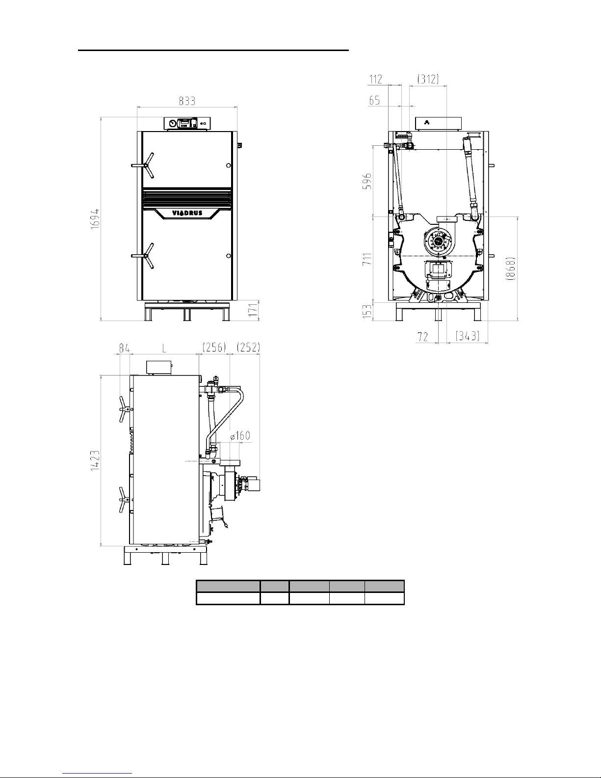
2.4 The main dimensions of the boiler
2.4.1 The main dimensions of the boiler Hefaistos P1 T
6 7
L
[mm] 998 1139
Fig.no. 2 The main dimensions of the boiler Hefaistos P1 T
Page 6
6
2.4.2 The main dimensions of the boiler Hefaistos P1 E
3 4 5
L
[mm] 575 716 857
Fig. no. 3 The main dimensions of the boiler Hefaistos P1 E
Page 7
7
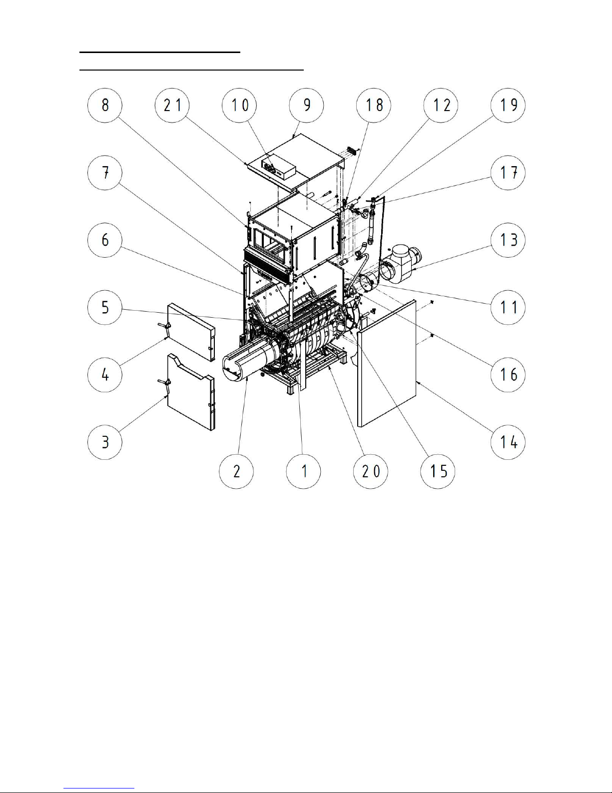
2.5 The main parts of boiler
2.5.1 The main parts of boiler Hefaistos P1 T
1 boiler drum
2 combustion chamber lining
3 ash pan door
4 stoking door
5 nozzle
6 feed hopper lining
7 boiler shell-left part
8 feed hopper
9 boiler shell-upper part
10 control box
11 boiler shell-rear part
12 outlet pipe
13 exhaust ventilator
14 boiler shell-right part
15 smoke adaptor
16 inlet pipe
17 two-way safety valve DBV 1 – 02
18 air release valve
19 draught controller
20 stand
21 boiler shell-front part
Fig.no. 4a) Main parts of boiler Hefaistos P1 T
Page 8
8
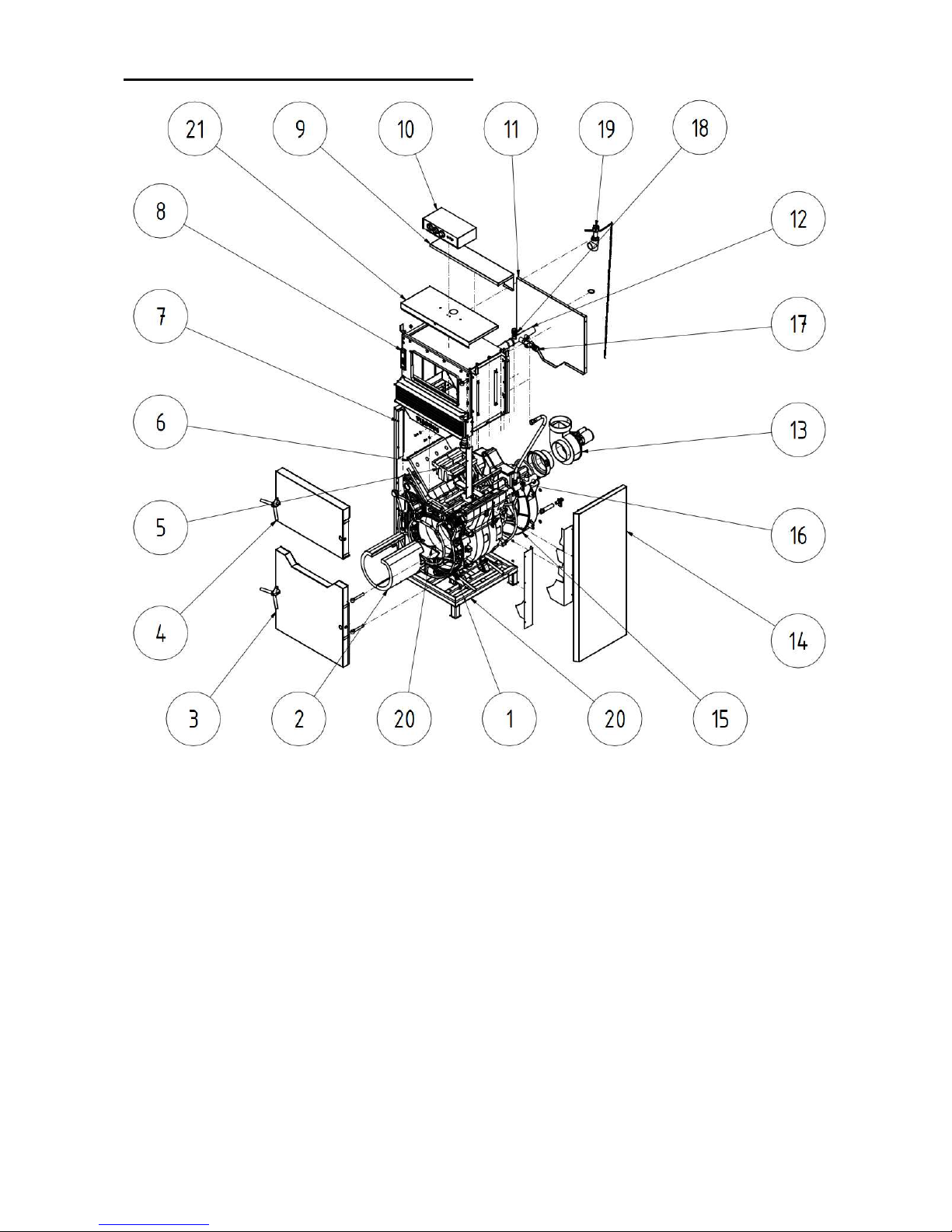
2.5.2 The main parts of boiler Hefaistos P1 E
1 boiler drum
2 combustion chamber lining
3 ash pan door
4 stoking door
5 nozzle
6 feed hopper lining
7 boiler shell-left part
8 feed hopper
9 boiler shell-upper part
10 control box
11 boiler shell-rear part
12 outlet pipe
13 exhaust ventilator
14 boiler shell-right part
15 smoke adaptor
16 inlet pipe
17 two-way safety valve DBV 1 – 02
18 air release valve
19 boiler shell-front part
20 stand
Fig. no. 4b) Main parts of boiler Hefaistos P1 E
Page 9

9
3. Installation instructions
3.1 Boiler construction
The sectional boiler drum made of grey cast iron according to EN 1561, quality 150 is the main part of the
boiler.
Pressure parts of boiler correspond to strength requirements according to EN 303 - 5 – Heating boilers –
Part 5: Heating boilers for solid fuels with manual or automatic stoking and nominal heat output of up to
300 kW – Terminology, requirements, testing and marking.
The boiler drum is made of sections by means of pressed boiler inserts (nipples) Φ 56 mm and rubber orings and secured by anchor bolts. The sections create combustion space, ash pan and water spaces and
also the convection part. The feed shaft consists of feed hopper, which is made of sheet metal intended for
combustion processes. The upper part of the feed hopper is water-cooled. The heating water inlet and outlet
are situated at the rear part of the boiler.
At the rear section of the boiler there is mounted the smoke adaptor with air exchanger and exhaust
ventilator. The return water connection is situated in the upper part of boiler drum. The heating water
connection is situated in the upper part of the feed hopper. Water inlet and outlet can be connected by
means of threaded pipes. The stoking door is mounted to the feed hopper and the ash pan door to the front
boiler section. The ash pan and stoking door are made with the possibility of left-right opening (see Fig.
No. 5).The whole boiler drum is insulated by using the harmless mineral insulation, which reduces the losses
caused by the heat transfer to the ambient. The boiler shell is coated with high-quality comaxit spray.
Fig.no. 5 Left-right opening
Page 10

10
3.2 Regulations and guidelines
A solid fuel boiler can only be installed by a firm holding a valid concession for boiler installation and
maintenance. A project according to the valid regulations must be prepared for the installation. Before the
boiler installation to an older heating system, the installation company must ensure that the whole heating
system is rinsed out (washed out). The heating system must be filled with water which meets the
ČSN 07 7401 requirements, especially its hardness must not exceed the required parameters.
Recommended values
Hardness mmol/l 1
Ca2+ mmol/l 0,3
Concentration of total Fe + Mn mg/l (0,3)*
*) recommended value
WARNING!!! The use of anti-freeze mixture is not recommended by the manufacturer.
In case the two-way safety equipment is signalling that boiler has been filled with the water which
does not meet the ČSN 077401 requirements it is necessary to treat the water in the system so that it
again meets this standard requirements.
a) To the heating system
ČSN 06 0310 Heating systems in buildings – Designing and installation
ČSN 06 0830 Heating systems in buildings – protecting device
ČSN 07 7401 Water and steam for thermal energy equipments with working pressure up to
8 MPa
EN 303-5 Heating boilers – Part 5: Heating boilers for solid fuels, manually and
automatically stoked, nominal heat output of up to 300 kW – Terminology,
requirements, testing and marking
b) To the chimney
ČSN 73 4201 Chimneys and flue gas ducting– designing, implementation and connection of
fuel consumers.
c) Regarding the fire regulations
ČSN 06 1008 Fire safety of heat installations
EN 13501-1 + A1 Fire classification of construction products and building structures – Part 1:
Classification using data from reaction to fire tests
d) To the electrical network
ČSN 33 0165 Electrical regulations. Marking the conductors with colours or digits.
Implementing regulations.
ČSN 33 1500 Electrical regulations. Electrical equipments revision
ČSN 33 2000-3 Electrical regulations. Electrical equipments Part 3: Setting the basic
characteristics.
ČSN 33 2000-4-41 Electric equipments: part 4: Safety chap. 41: Protection against electric shocks.
ČSN 33 2000-5-51 ed. 2 Electrical regulations. Electrical equipments construction.
ČSN 33 2130 Electrical regulations. Internal wiring.
ČSN 33 2180 Electrical regulations. Connection of electrical devices and appliances.
ČSN 34 0350 Electrical regulations. Regulations for mobile connections and cord extension
sets.
EN 60079-10 Electrical regulations. Regulations for electric equipments at the places with
danger of explosion of flammable gases and vapours
EN 60 335-1 ed.2 Electrical appliances for household and similar purposes – Safety – Part 1:
General requirements.
EN 60 335-2-102 Electrical appliances for household and similar purposes – Safety – Part 2-102:
Particular requirements for appliances burning gas, oil and solid-fuel and having
electrical connections.
EN 60445 ed. 3 Basic and safety principles for man – machine interface, marking and
identification
EN 60446 ed.2 Basic and safety principles when operating the machinery Identification of
conductors by colours or numerals
e) To the system of HWS heating
ČSN 06 0320 Heating systems in buildings – Hot water preparation – Designing and planning
ČSN 06 0830 Heating systems in buildings – Safety devices.
ČSN 73 6660 Internal water conduits
Page 11

11
3.3 Placement options
Boiler is approved for installation in non-residential premises (for example cellar, corridor etc.) and
in AA5/AB5 basic environment according to ČSN 33 2000-3.
The boiler is equipped with a movable mains supply and a plug. According to EN 60 335 – 1 ed. 2 Art. 7.12.4
the boiler must be positioned in a way so that the plug is accessible.
The installation of the boiler must comply with all requirements of ČSN 06 1008
Boiler positioning with regard to fire regulations:
1. Positioning on the floor made of incombustible material
− The boiler must be installed on a fireproof bottom, which exceeds the boiler platform by 20 mm on the
sides (see fig. No. 6).
Number of sections
3 4 5 6 7
L [mm]
695 695 975 975
Fig. No. 6 Socle dimensions
2. A safe distance from the combustible materials:
− when installing and operating the boiler it is necessary to keep a safety distance of 200 mm from the
materials of combustibility grade A1, A2, B and C (D);
− for easily combustible materials of combustibility grade E (F), which quickly burn and burn themselves
even after removal of ignition source (such as paper, cardboard, asphalt and tar paper, wood and
wood-fiber boards, plastics, floor coverings) the safe distance has to be doubled, i.e. to 400 mm;
− safe distance should be doubled as bulb where the grade of reaction to fire has not been proved.
Tab. no. 2 Grade of reaction to fire
Grade of reaction to fire
Examples of building materials and products included in the reaction to fire
(Extract from EN 13 501-1 + A1)
A1
– incombustible
Granite, sandstone, concrete, bricks, ceramic tiles, mortars, fireproof plasters, …
A2
– combustible with difficulty
acumin, izumin, heraklit, lignos, boards and basalt felt, fibreglass boards,...
B
– hardly combustible
Beech and oak wood, hobrex boards, plywood, werzalit, umakart, sirkolit,...
C (D)
– medium combustible
Pinewood, larch, whitewood, chipboard and cork boards, rubber flooring,...
E (F) – easily combustible
Asphaltboard, fibreboards, cellulose materials, polyurethane, polystyrene,
polyethylene, PVC,…
Page 12
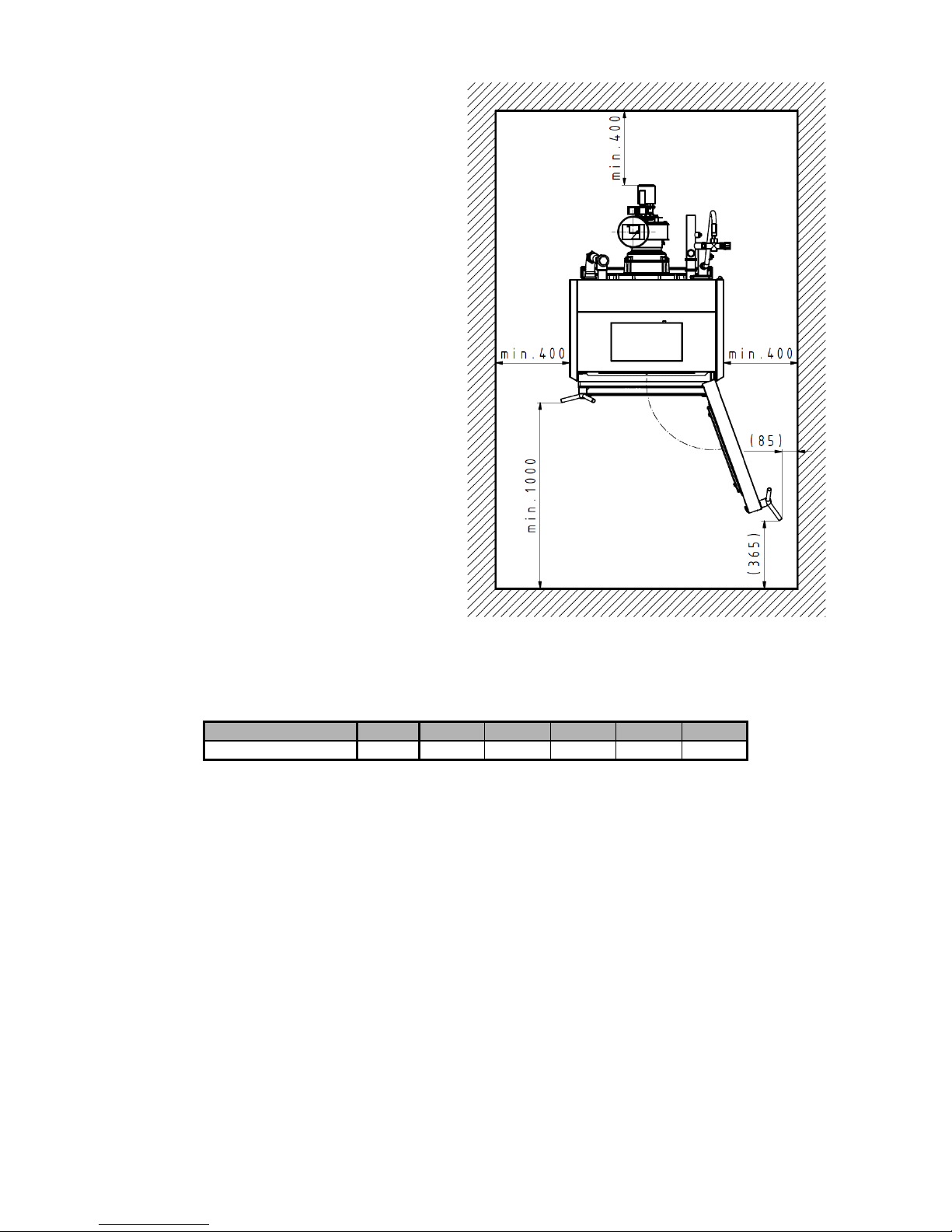
12
Location of boiler with regard to
necessary handling space:
− at least 1000 mm handling space must
be left in front of the boiler;
− the minimum distance between the rear
part of the boiler and wall is 400 mm;
− on both sides keep the space at least
400 mm for access to the rear part of the
boiler.
Fuel location:
− it is forbidden to store the fuel behind or
next to the boiler in a distance lower
than 400 mm;
− it is forbidden to store the fuel between
two boilers in boiler-room;
− it is recommended by the manufacturer
that minimum distance of 1000 mm
− is maintained between the boiler and
fuel or the fuel should be stored in
another room.
Fig.no. 7 Location of boiler in boiler room
A continuous air supply for burning and eventual ventilation must be ensured for the room where the
boiler is installed.
Air consumption of boiler:
Number of sections
3 4 5 6 7
Air cinsumption [m3.h
-
1
] 100 140 170 285 390
The choice of the right size of boiler
The choice of the right size of boiler i.e. its heat output is very important condition for economic operation
and a correct function of the boiler. The boiler must be chosen so that its rated thermal output corresponds to
the heat losses of the building. The rated output is calculated according to valid standards for outside
temperatures –12 °C, -15 °C and –18 °C. The choice of boiler with too high rated output (oversizing) results
in increased tarring and retting of the boiler. That’s why it is not suitable to use boilers with the output higher
than the heat losses of the building
This does not apply in case the boiler is connected in the system with a storage tank.
Chimney draught
The chimney with its proper draught is a fundamental prerequisite for a good function of boiler. It influences
both boiler output and its efficiency. The boiler may be connected to chimney vent which has a sufficient
draught (see chapter 2.3) and the revision must be carried out by an authorized organization.
Page 13

13
3.4 Delivery and accessories
Boiler is delivered according to the order and on the pallet there is placed the complete boiler drum plus
boiler shell in a wooden casing. The accessories are inside the boiler drum and are accessible when opening
the stoking door has been opened. The boiler is packed in shipping wrapping and it must not be tipped over
during transport.
.
3.4.1 Delivery and accessories - Hefaistos P1 T
Standard boiler delivery:
• the boiler on the pallet in the casing with the relevant number of sections including the boiler shell
• cleaning kit (cleaner, hook, brush with handle, poker, dowel 2 pcs, direct hook with thread 2 pcs)
• complete control box with electro accessories 1 pc
• filling and drain valve Js 1/2“ 1 pc
• complete draft controller 1 pc
• connecting hose G 3/4“ with sealing G 3/4“ 1 pc
• connecting hose G 1½“ with sealing G 1½“ 1 pc
• T –joint G 1 ½“ 1 pc
• long bend G 1 ½“ 1 pc
• boiler plug 2 pcs
• adaptor reduced N4 1 ½“ x ¾“ 1 pc
• air release valve 1 pc
• ventilator (6 – 7 sect.) 1 pc
• manipulation key 1 pc
• two way safety valve DBV 1 – 02 1 pc
• business/technical documentation
By request:
• Safety valve 1 pc
The boiler accessories ordered „by request“ are not included in the basic price of the boiler.
3.4.2 Delivery and accessories - Hefaistos P1 E
Standard boiler delivery:
• the boiler on the pallet in the casing with the relevant number of sections including the boiler shell
• cleaning kit (cleaner, hook, brush with handle, poker, dowel 2 pcs, direct hook with thread 2 pcs)
• complete control box with electro accessories 1 pc
• filling and drain valve Js 1/2“ 1 pc
• complete draft controller 1 pc
• connecting hose G 3/4“ with sealing G 3/4“ 1 pc
• connecting hose G 1½“ with sealing G 1½“ 1 pc
• T –joint G 1 ½“ 1 pc
• long bend G 1 ½“ 1 pc
• boiler plug 2 pcs
• radiator plug 1 1/2“ 1 pc
• sealing 1 1/2“ 1 pc
• air release valve 1 pc
• shell with ventilator (3 – 5 sect.) 1 pc
• manipulation key 1 pc
• two way safety valve DBV 1 – 02 1 pc
• business/technical documentation
By request:
• Safety valve 1 pc
The boiler accessories ordered „by request“ are not included in the basic price of the boiler.
Page 14

14
3.5 Installation process
3.5.1 Installing the boiler drum
3.5.1.1 Installing the boiler drum – Hefaistos P1 T (see Fig. no. 8 and 9)
1. Set the boiler drum on the socle (underlay).
2. Dismount the rear part of the shell (1) by means of 4,8 x13 screws and serrated lock washers 5,3 - see
detail A and the upper part of the shell (2) according to the Figure no.8.
3. Install T- joint (13), the reduced adaptor (16) into T- joint, then mount the long bend (12) and the
interconnection pipe G 1 ½“ (14) via sealing 1 ½“ according to the Fig. no.9a.
4. Install the outlet pipe. Install the air-release valve (10) and two-way safety valve DBV 1 – 02 (8) to the
heating water outlet (6) (see Fig. no. 9a, 14, 15) – the valve can be installed only in the horizontal
position. The heating water outlet pipe (6) must be connected via a demountable joint to the heating
system.
5. The return water inlet (3) must be connected via a demountable joint to the heating system.
6. Install the filling and drain valve G 1/2“ (1).
7. Install the control box see chap. no. 3.5.2.
8. Screw the draft controller (15) into the opening in the reduced adaptor (16). The procedure of setting the
boiler draft controller is shown in chapter no.5.1.1-Operation.
9. Put the smoke pipe on the exhaust ventilator (2) and push it into the chimney hole. The smoke pipe
diameter is stated in tab. No.1.
3.5.1.2 Installing the boiler drum – Hefaistos P1 E (see Fig. no. 8 and 9)
1. Set the boiler drum on the socle (underlay).
2. Dismount the rear part of the shell (1) by means of 4,8 x13 screws and serrated lock washers 5,3 - see
detail A and the upper part of the shell (2) according to the Figure no.8.
3. Install T- joint (13), the radiator plug (15) into T- joint, then mount the long bend (12) and the
interconnection pipe G 1 ½“ (14) via sealing 1 ½“ according to the Fig. no.9b.
4. Install the outlet pipe. Install the air-release valve (10) and two-way safety valve DBV 1 – 02 (8) to the
heating water outlet (6) (see Fig. no. 9b, 14, 15) – the valve can be installed only in the horizontal
position. The heating water outlet pipe (6) must be connected via a demountable joint to the heating
system.
5. The return water inlet (3) must be connected via a demountable joint to the heating system.
6. Install the filling and drain valve G 1/2“ (1).
7. Install the control box see chap. no. 3.5.2.
8. Put the smoke pipe on the exhaust ventilator (2) and push it into the chimney hole. The smoke pipe
diameter is stated in tab. No.1
Page 15

15
Fig.no. 8 Dismantling of the upper rear part of the boiler shell
1. boiler shell-rear part
2. boiler shell-front part
3. boiler shell-upper part
Page 16
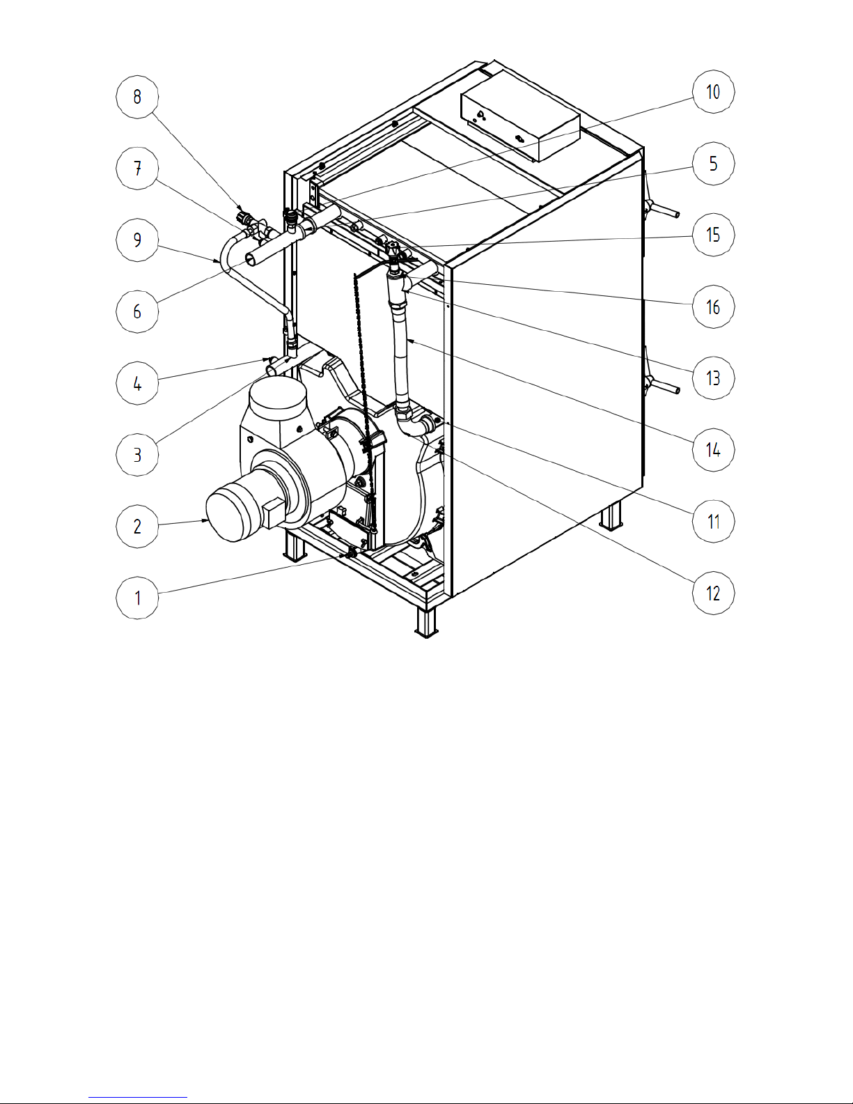
16
1 filling and drain valve G 1/2“
2 shell with ventilator
3 return water input (with distribution pipe)
4 boiler plug 1/2“
5 sleeve 1 1/2“
6 heating water output
7 boiler plug 1/2“
8 two-way safety valve DBV 1 – 02
9 interconnecting hose 3/4“
10 air-release valve 1/2“
11 pipe-output
12 long bend 1 1/2“
13 T-joint 1 1/2“
14 interconnecting hose 1 1/2“
15 draught controller
16 adaptor reduced 1 1/2“ na 3/4“
Fig.no. 9a) Installing the boiler drum – Hefaistos P1 T
Page 17
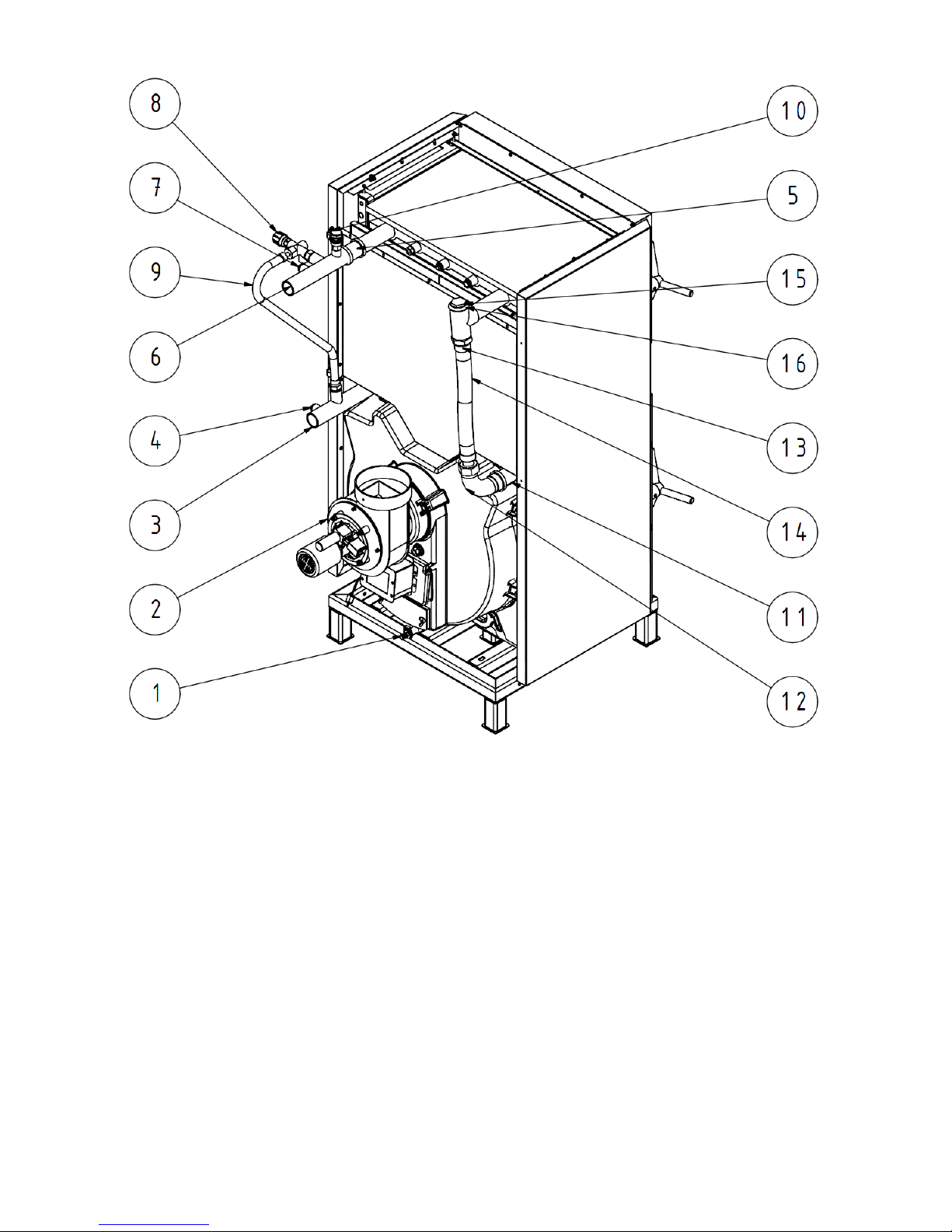
17
1. filling and drain valve G 1/2“
2. shell with ventilator
3. return water input (with distribution pipe)
4. boiler plug 1/2“
5. sleeve 1 1/2“
6. heating water output
7. boiler plug 1/2“
8. two-way safety valve DBV 1 – 02
9. interconnecting hose 3/4“
10. air-release valve 1/2“
11. pipe-output
12. long bend 1 1/2“
13. T-joint 1 1/2“
14. interconnecting hose 1 1/2“
15. radiator plug 1 1/2“
16. sealing 1 1/2“
Fig.no. 9b) Installing the boiler drum – Hefaistos P1 E
Page 18

18
3.5.2 Mounting the control box
3.5.2.1 Mounting the control box – Hefaistos P1 T (see Fig. no. 10)
1. Dismount the upper part of the control box (3) by means of 2 screws M5 x 12 and serrated lock washers
5,3 – see detail B. Thread the capillaries of the control box thermostats through the opening in the upper
part of the shell and by means of 2 pc screws M5 x 25 and serrated lock washers 5,3 screw the control
box to the upper front part of the shell (4) – see detail A.
2. Put the upper part of the shell (4) on the side parts of the shell (1, 2):
- Insert the flue gas thermostat capillary into the smoke adaptor basin;
- screw the manometer capillary into the check valve and insert the capillaries of thermometer and
thermostats into the basin in the water space of the feed hopper and secure by the spring of
capillaries.
3. In the upper part of the boiler shell (5) break out a perforated opening either on the right or left side,
depending on the need. Install the bushing ICOTEK.
4. Carry out the wiring (see chap. 4.8).
It is necessary to ensure that the wiring and capillaries do not directly touch the feed hopper.
5. Insert the front upper part of shell (4) and upper part of the shell (5) on the side parts of the shell (1, 2).
6. Screw the rear part of the shell (6) to the upper (5) and side parts of the shell (1, 2) by means of
11 pc screws C 4,8 x13 and serrated lock washers 5,3 – see detail B.
3.5.2.2 Mounting the control box – Hefaistos P1 E (see Fig. no. 10)
1. Install the limit switch see chap. 3.5.3.
2. Dismount the upper part of the control box (3) by means of 2 screws M5 x 12 and serrated lock washers
5,3 – see detail B. Thread the capillaries of the control box thermostats through the opening in the upper
part of the shell and by means of 2 pc screws M5 x 25 and serrated lock washers 5,3 screw the control
box to the upper front part of the shell (4)- see detail A.
3. Put the upper part of the shell (4) on the side parts of the shell (1, 2):
- Insert the flue gas thermostat capillary into the smoke adaptor basin;
- Screw the manometer capillary into the check valve and insert the capillary of safety thermostat and
the sensor of boiler water output temeperature (ÚT) into the basin in water space of the feed hopper
and secure by the spring of capillaries.
4. In the upper part of the boiler shell (5) break out a perforated opening either on the right or left side,
depending on the need.Install the bushing ICOTEK.
5. Carry out the wiring (see chap.4.8). Put the sensor of flue gases temperature on the flue gas ducting
and secure by means of a self-drilling screw in the distance 3 x D (diameter of the the flue gas ducting)
from the shell of ventilator.
It is necessary to ensure that the wiring and capillaries do not directly touch the feed hopper.
6. Insert the front upper part of shell (4) and upper part of the shell (5) on the side parts of the shell (1, 2).
7. Screw the rear part of the shell (6) to the upper (5) and side parts of the shell (1, 2) by means of 11 pc
screws C 4,8 x13. and serrated lock washers 5,3 – see detail B.
Page 19

19
1 left side part of shell with
insulation
2 right side part of shell
3 upper part of the control box
4 upper front part of the shell
5 upper part of the shell
6 rear part of the shell
A Mounting the control box to the upper part of the shell
B Mounting the upper part of the control box
Fig. no. 10 Mounting the control box
Page 20
20
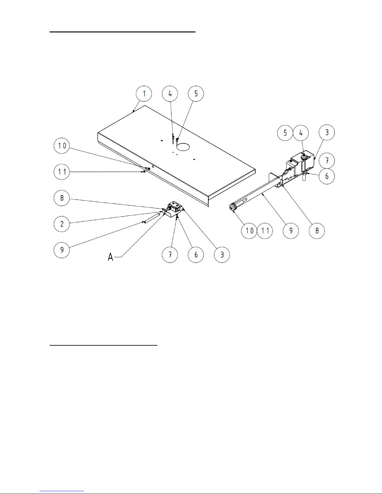
3.5.3 Limit switch installation – Hefaistos P1 E
1. Connect the limit switch according to the electrical connection see. Chap. 4.8
2. Insert the rod (9) into the left hole (A) in consoles (2). Then mount the circlip 7 (8).
3. By means of screws M4 x 40 (4) and washers 4.3 (6) mount the limit switch (3) to the consoles (2) and
the upper part of shell (1) and secure with nuts M4 (7) and washers 4.3 (6).
4. Screw the bolt M5x 20 (11) with washers 5.3 (10) on the rod (9) in the front upper part of the shell
(if necessary- when testing the limit switch- we can change the number of washers (10).
A – left hole of the console
1. upper part of the shell
2. console
3. limit switch
4. screw M 4 x 40
5. washer 4,3
6. washer 4,3
7. nut M4
8. console
9. rod
10. washer 5,3
11. screw M 5 x 20
Fig. no. 11 Limit switch installation
3.5.4 Installation of cleaning tools
Use the common assembly tools and leather gloves when mounting or dismounting the brush, tip on the
spike and cleaner (if included in the delivery).
Page 21

21
4. Commissioning
Putting the boiler into operation can be performed only by professional installation companies
authorized to carry out this work.
.
4.1 Control activities before starting
Before putting the boiler into operation it is necessary to check:
1. Filling the heating system with water (inspection of the thermomanometer) and the tightness of the
system. Heating system must be thoroughly rinsed out in order to wash out all impurities that might be
deposited in piping or radiators and consequently would cause damage to the pump. Water for filling the
boiler and heating system must be clear and colourless, without any suspended substances, oil and
chemically aggressive substances. Its hardness must comply with ČSN 07 7401 and in case of
dissatisfactory hardness the water must be treated. Even a repeated heating of water with a higher
hardness does not prevent the salts from segregation on the walls of boiler drum. By precipitation of 1
mm calcite at a given point the heat transfer from metal to water is reduced by 10 %.The heating
systems with an open expansion tank allow a direct contact between the heating water and the
atmosphere. During the heating season the expanding water in the reservoir absorbs the oxygen which
increases the corrosive effects and at the same time lot of water evaporates. Only the water treated to
the values according to ČSN 07 7401 can be used for refilling.
During the heating season it is necessary to maintain a constant water volume in the heating system.
When refilling the water in the heating system it is necessary to ensure that no air is sucked into the
system. The water from boiler and the heating system must never be discharged or be used except the
emergency cases like the repairs, etc. By emptying the boiler and filling it with new water the danger of
corrosion and the scaling is increased.
If it is necessary to refill water in the heating system, we only do it when the boiler has cooled down so
that the heat exchanger cannot be damaged.
2. Connection to the chimney - this connection can be made only with the consent of the competent
chimney company (revision of chimney).
3. Connection of the two-way safety valve DBV 1 – 02.
4. Connection to electrical network.
5. Tightness of the stoking door and ash pan doors:
Approximately in the middle of sealing cord there must be about 2 mm groove (see Fig. no. 12-12, 13)
uniformly along the whole circumference as the imprint of the sealing surface. If there is no groove in
the sealing cord the door should be adjusted. The untightness can be removed both on the side of
handle and on the side of hinges. On the side of hinges there must be dismounted the side shell and the
eyes of hinges must be adjusted by means of nuts M 16.
Tightening of the handle (see Fig.no. 12) is carried out as follows:
•
loosen the screws of handle (9) and remove the handle (3)
•
loosen the locking nuts (5)
•
loosen the set screw (6) as required
•
put on the handle (3) and secure with locking screws (9)
•
close the door
•
tighten the set screw (6)
•
loosen the locking screws (9)
•
remove the handle (3) and tighten the nuts (5)
•
put on the handle (3) and secure with screws (9).
Slumping or otherwise misaligned door can be centered by loosening the door hinges:
•
in case of stoking door by releasing three bolts M 10 the inside the door at hinges.
•
in case of ash pan door by releasing the hinges after dismantling the front shell.
Page 22
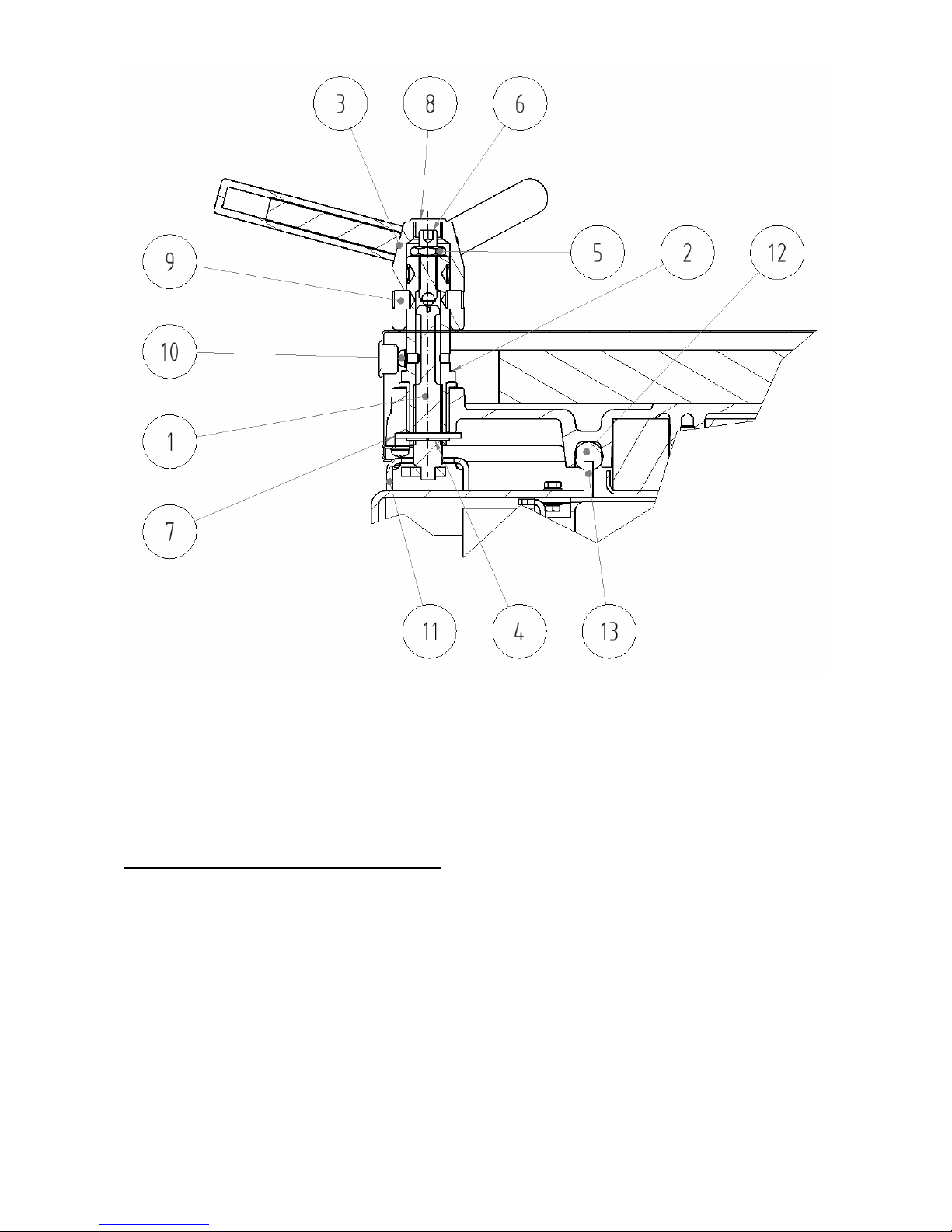
22
1. Closing
2. Axis of handle
3. Handle
4. Flexible circlip
5. Securing nut
6. Washer
7. Setscrew
8. Blind flange
9. Locking screw of the handle
10. Locking screw of closing
11. Counterpart of closing
12. Sealing cord
13. Sealing surface of feed hopper
Fig.no. 12 Setting of the handle of ash pan door and stoking door
4.2 Putting the boiler into operation
1. Make a fire in boiler
2. Bring the boiler to the necessary operating temperature. The recommended temperature of the output
water is 80 °C.
3. Switch on the exhaust ventilator
4. Check the functionality of two way safety valve DBV 1 – 02
5. Operate the boiler in operating state according to appropriate standards.
6. Check again the boiler for leakage
7. Make the user acquainted with operation and maintenance
8. Make a record in the Guarantee certificate.
Page 23
23
4.3 Regulatory and signaling elements
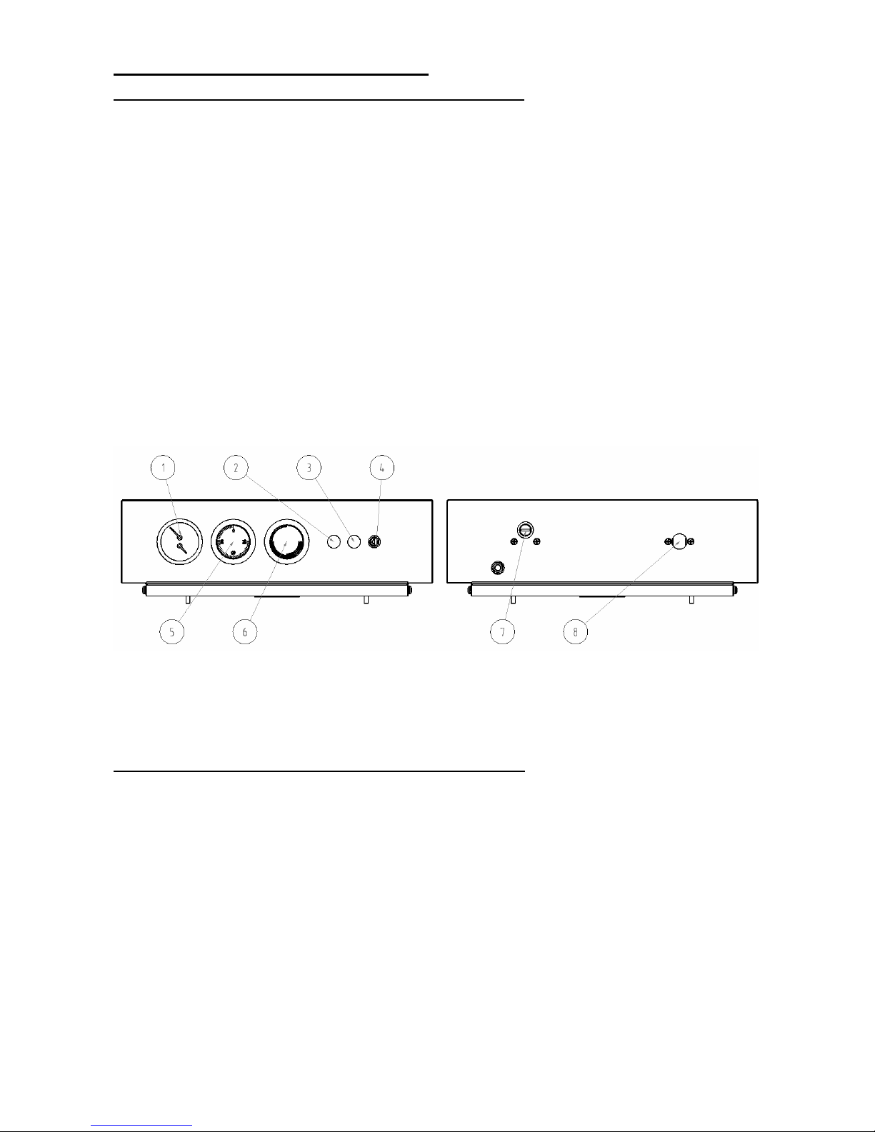
4.3.1 Regulatory and signaling elements – Hefaistos P1 T
Combustion air is brought to boiler by means of a throttle valve (choking valve), which is placed on the
smoke adaptor. By means of the air exchanger the combustion air will be distributed to the nozzle as the
primary air and into lining of combustion chamber as the secondary combustion air and both are controlled
by draft controller.
Thermomanometer – is used for measuring the water temperature and pressure in boiler.
Flue gases thermoregulator (range 0 – 300 °C) – serves for switching off the ventilator after the fuel has
burnt out. When making a fire in boiler we set the flue gases thermoregulator to „minimum“– 0 °C. In the
stage of flaring we set the flue gases thermoregulator to operating temperature, which is to be set by user. It
is necessary to find the right value so that the ventilator will switch off after the fuel has burnt out. If the flue
gases temperature drops below the set value, the thermo-regulator will switch off the exhaust ventilator If we
want to make the ventilator work again, we have to set the flue gases thermoregulator to lower temperature.
Operating thermoregulator – controls the run of ventilator depending on the outlet water temperature.
Safety thermoregulator (irreversible) – serves as a protection against boiler overheating. It is set to 95 °C.
In case of a fault it is necessary- after the boiler has cooled down- to deactivate the safety thermoregulator
manually. Due to the activation of safety thermoregulator the exhaust ventilator is switched off and it is
signalled by a orange pilot light on the control box panel.
Thermoregulator of the pump– is used for setting the temperature when the pump is switched on (we
recommend setting to 50 – 55 °C).
Draught controller– serves for the control of throttle valve (choking valve) which is installed on the smoke
adaptor of the boiler.
1 – Termomanometer
2 – Signalling the safety thermoregulator
3 – Signalling the run ov ventilator
4 – Circuit breaker
5 – Operating thermoregulator
6 – Flue gases thermoregulator
7 – Safety thermoregulator
8 – Thermoregulator of the pump
Fig. no. 13a) Control box – Hefaistos P1 T
4.3.2 Regulatory and signaling elements – Hefaistos P1 E
Combustion air is brought to boiler by means of a throttle valve (choking valve), which is placed on the
smoke adaptor. By means of the air exchanger the combustion air will be distributed to the nozzle as the
primary air and into lining of combustion chamber as the secondary combustion air and both are controlled
by draft controller.
Thermomanometer – is used for measuring the water temperature and pressure in boiler.
Safety thermoregulator (irreversible) – serves as a protection against boiler overheating. It is set to 95 °C.
In case of a fault it is necessary- after the boiler has cooled down- to deactivate the safety thermoregulator
manually. Due to the activation of safety thermoregulator the exhaust ventilator is switched off and it is
signalled by a orange pilot light on the control box panel.
Controller ST 81 processes data from sensors of output water temperature, hot water and flue gases
temperature. According to the data in this way the modulated exhaust ventilator, central heating pumps and
HW (hot water) pumps are controlled.
Limit switch of stoking door every time you open the stoking door (opening the limit switch) the exhaust
ventilator is activated at its maximum power and thus prevents the escape of flue gases into the space
where the boiler is located. After closing the stoking door (closing the limit switch) the fan power returns into
automatic mode.
Page 24
24
Flap of throttle valve (choking valve) - opens automatically when fan is running. When you stop the fan
the flap is closed by means of counterweight. The weights should be adjusted so that the flap at full fan
power is opened to about 45 °.
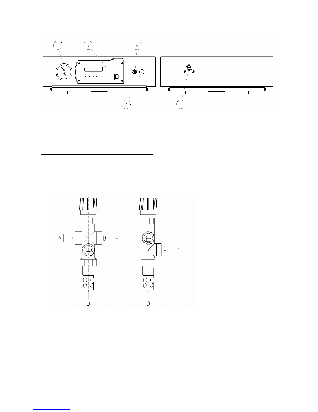
1 – Manometer
2 – Signalling of the safety thermoregulator
3 – Controller ST – 81
4 – Circuit breaker
5 – Safety thermoregulator
Fig.no. 13b) Control box with regulator ST – 81 – Hefaistos P1 E
4.5 Equipment to remove excess heat
The two way safety valve DBV 1 - 02 is used for surplus heat removal in case the water temperature
in boiler exceeds 95 °C.
In case the system is equipped with a two- way safety valve DBV 1 – 02 and it comes to the boiler
overheating (the outlet water temperature is above 95 °C) then two-way safety valve will create a cold water
circuit until the temperature drops below the limit temperature. At this moment there is closed the draining
cooling system and the inlet of cold water inlet used for refilling the system.
.
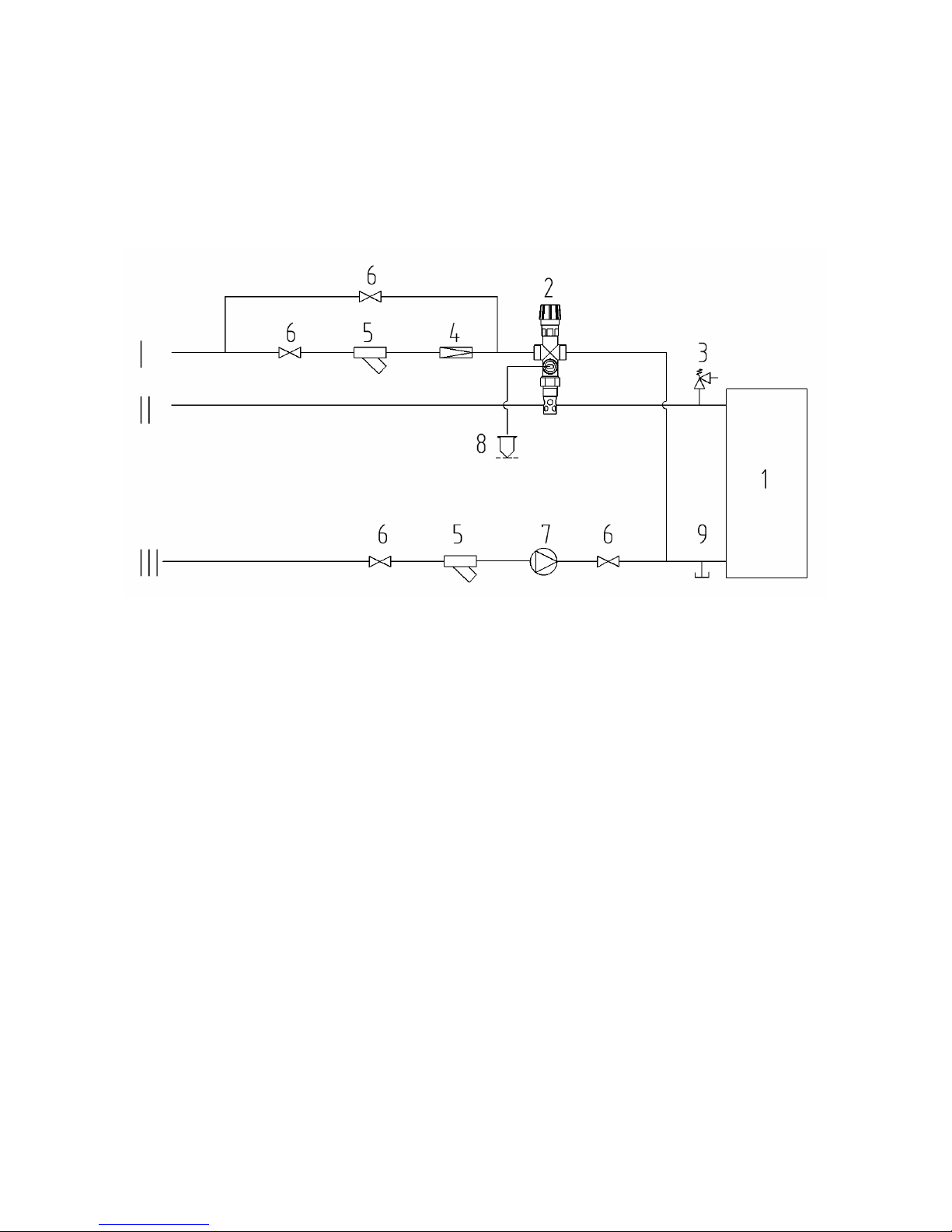
Fig.no. 14 Two-way safety valve DBV 1 – 02
Technical data on the two-way safety valve DBV 1 – 02 (made by Regulus)
Opening temperature (limit): 100 °C (+0° - 5 °C)
Maximum temperature: 120 °C
Maximum pressure on the boiler side: 400 kPa (4 bar)
Maximum pressure on the water side: 600 kPa (6 bar)
Nominal flow at p 100 kPa (1 bar): 1,9 m3/h
A – cold water inlet
B – outlet to the boiler
C – outlet to the waste
D – inlet from the boiler
Page 25
25
Usage
The two way safety valve DBV 1 – 02 is used as a protection of heating boilers against overheating. In the
valve body there is the drain and filling valve controlled by a thermostatic member. When the limit
temperature is reached both the drain and filling valve are opened which means that cold water is flowing
into boiler and the hot water is discharged. When the temperature drops below limit, both the drain and filling
valve are closed simultaneously.
Caution! It is not a compensation for safety valve
In case the two-way safety equipment is signalling that boiler has been filled with the water which
does not meet the ČSN 077401 requirements it is necessary to treat the water in the system so that it
again meets this standard requirements.
1 – Boiler
2 – Two-way safety valve DBV 1 – 02
3 – Safety valve
4 – Reduction valve
5 – Filter
6 – Ball valve
7 – Pump
8 – Outlet of of excess heat
9 – Drain valve
I – Cold water input
II – Heating water output
III – Return water input
Fig.no. 15 Recommended diagram of connection of two-way safety valve DBV 1 - 02
Installation
The installation can be only carried out by a qualified person. For the correct operation of the thermostatic
two-way safety valve it is necessary to comply with the conditions stipulated for its installation and observe
the flow directions indicated on its body. The safety valve is alway mounted in the output pipe of boiler or
directly on the upper part of boiler where the hot water leaves boiler and is transported into heating system.
When installing the valve it is necessary to check whether the use of the 3/4“ sleeve, which can be both in
pipeline and on boiler ensures a complete immersion of the thermostatic member of valve after the valve
installation. After the installation in the sleeve the waste piping will be connected in the point “C" (see. fig.
No. 14) and it leads the hot water from boiler into the sewer. In point "A" (see. fig. No.14) there the cooling
water inlet is connected (Fig. no.15) and this water will ensure cooling of oiler after setting the valve into
operation.At the cooling water inlet there must be installed the filter for capture of mechanical impurities. In
the point “B” (see Fig. no.14) there is connected the piping which according to Fig. no.15 is led into the return
pipe of heating system near the boiler.
Regular maintenance
Once a year it is necessary to turn the head of the safety valve to remove possible impurities settled in the
valve. Clean the filter in the inlet of cooling water.
Important
It is not possible to turn the flows and that’s why it is important to observe markings of filling and draining as
indicated on the valve.
Page 26
26
4.6 Equipment for heat removal - storage tanks
We require the connection of pyrolytic boiler with storage tanks.
Advantages:
•
A lower fuel consumption (by 20 – 30 %), the boiler is working at full power and optimal
efficiency till the fuel has burnt out
•
Long service life of boiler and chimney – minimum production of tars and acids
•
Combination of heating elements and floor heating
•
More comfortable heating
•
Ecological heating
•
Possibility of combination with other types of heating
The calculation of the stack exchanger lowest volume
Vsp = 15Tb x QN (1-0,3 x (QH/Q
min
)
where:
Vsp storage tank volume (liters)
QN rated thermal output (kW)
Tb burning time (hrs)
QH heat load of buildings (kW)
Q
min
the lowest heat output (kW)
Dimensions of storage tanks for central heating boilers that are operated with the individual stipulated fuels
must be determined according to output which must have the biggest storage tank.
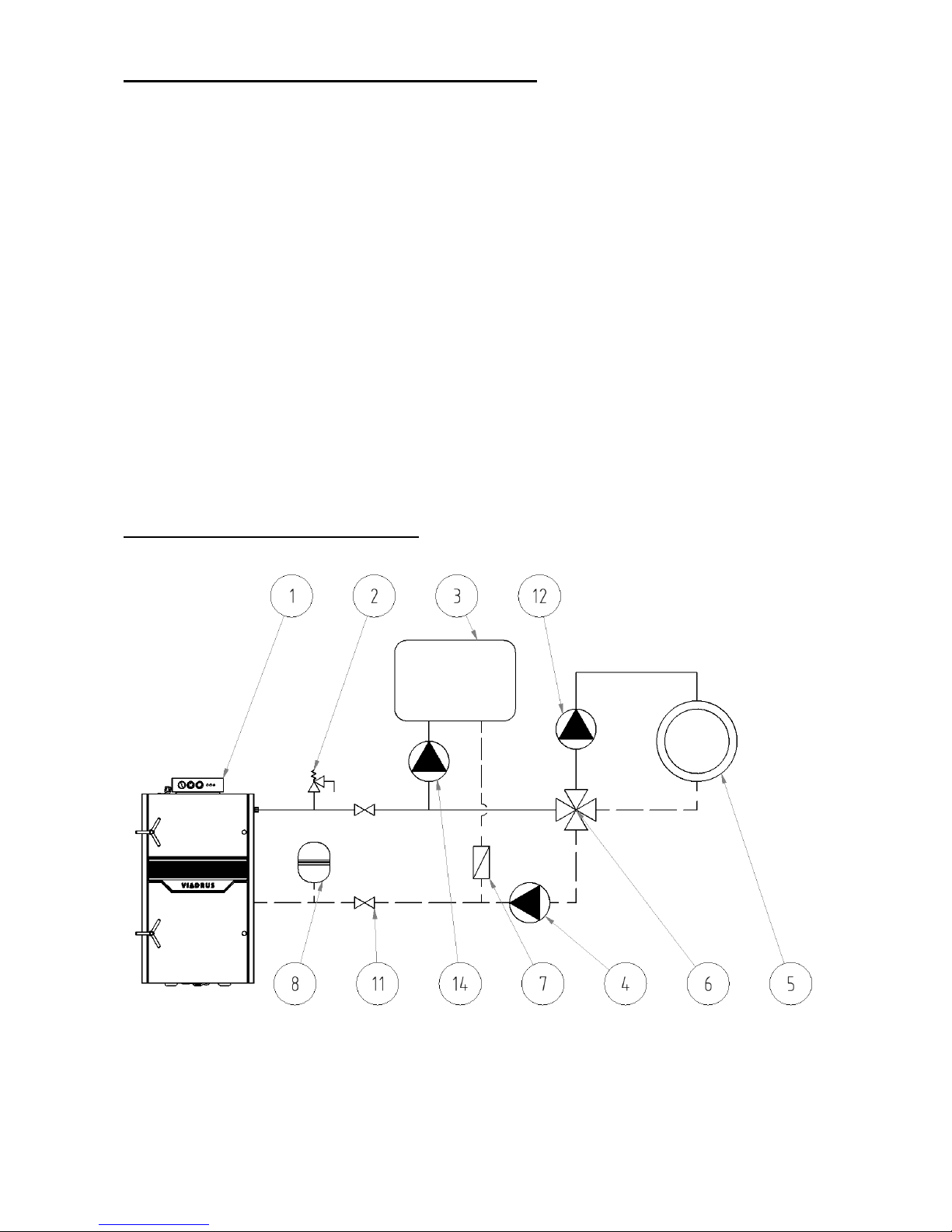
4.7 Diagram of connection-boiler
Fig.no. 16 Recommended diagram of the boiler connected with a four-way mixing valve
Page 27

27
Fig.no. 17 Recommended diagram of the boiler connected with a three-way mixing valve
Fig.no.18 Recommended diagram of the boiler connected with a storage tank
Legend to Fig. no. 16 – 18:
1 – Boiler
2 – Safety valve
3 – Reservoir of hot water (TV)
4 – Pump
5 – Heating system
6 – Four-way mixing valve
7 – Clack valve
8 – Expansion tank
9 – Storage tank
10 – Three-way valve controlled by a higher-level regulation
11 – Valve
12 – Heating circuit pump controlled by a higher-level
regulation
13 – Thermo valve or ladomat
14 – Charging pump of HW tank controlled by HW tank
thermoregulator, HW sensor or higher-level regulation
HW
Page 28
28
4.8 Electrical connection
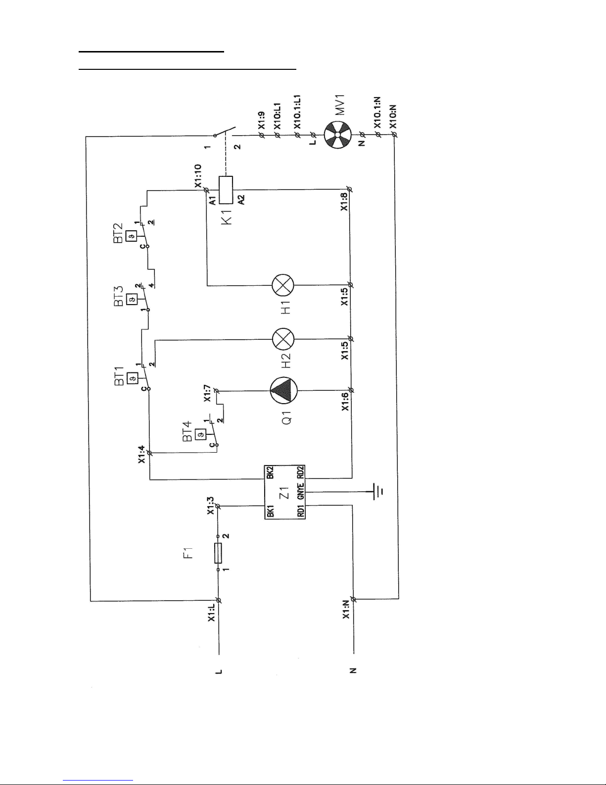
4.8.1 Electrical connection – Hefaistos P1 T
Fig.no. 19 Circuit diagram of connection - boiler Hefaistos P1 T
LEGEND:
BT1 SAFETY THERMOREGULATOR
BT3 FLUE GASES THERMOREGULATOR
BT2 OPERATINGÍ THERMOREGULATOR
BT4 PUMP THERMOREGULATOR
F1 FUSE 6,3 A
H1 SIGNALLING THE RUN OF VENTILATOR (GREEN)
H2 SIGNALLING THE SAFETY THERMOREGULATOR (ORANGE)
K1 CONTACTOR OF EXHAUST VENTILATOR
MV1 EXHAUST VENTILATOR
Q1 PUMP
X1 TERMINAL BOARD OF BOILER
X10 CONNECTOR OF VENTILATOR (SOCKET)
X10.1 CONNECTOR OF VENTILATOR (PLUG)
Z1 SUPPRESSION COMPONENT
Page 29
29
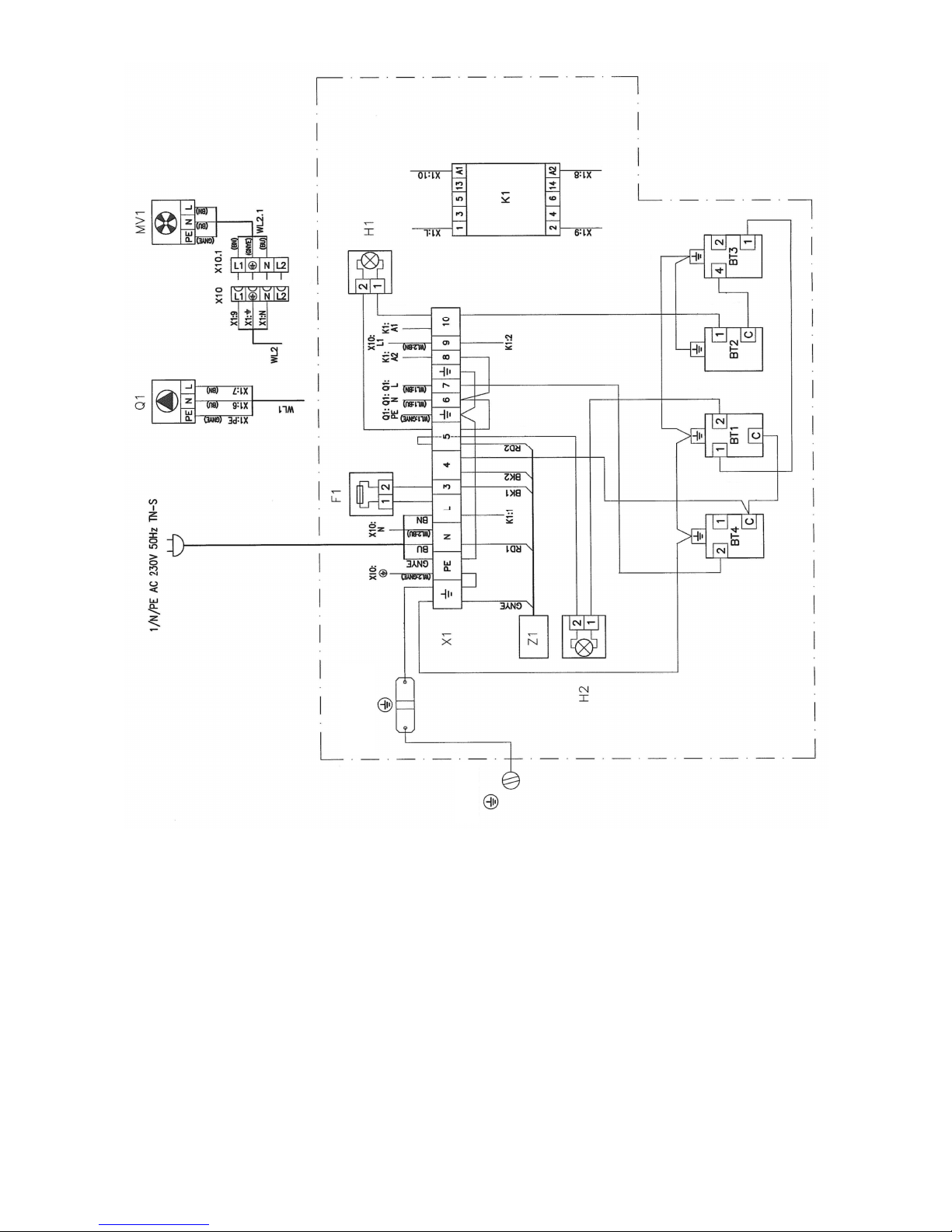
LEGEND:
BT1 SAFETY THERMOREGULATOR
BT3 GLUE GASES THERMOREGULATOR SPALIN
BT2 OPERATING THERMOREGULATOR
BT4 PUMP THERMOREGULATOR
F1 FUSE 6,3 A
H1 SIGNALLING THE RUN OF VENTILATOR (GREEN)
H2 SIGNALLING THE SAFETYHO THERMOREGULATOR (ORANGE)
K1 CONTACTOR OF EXHAUST VENTILATOR
MV1 EXHAUST VENTILATOR
Q1 PUMP
X1 TERMINAL BOARD OF BOILER
X10 CONNECTOR OF VENTILATOR (SOCKET)
X10.1 CONNECTOR OF VENTILATOR (PLUG)
Z1 SUPPRESSION COMPONENT
Fig.no. 20 Diagram of connection- boiler Hefaistos P1 T
Wire colour
GNYE green yellow
GN green
YE yellow
RD red
BK black
BN brown
BU blue
Page 30
30
4.8.2 Electrical connection – Hefaistos P1 E
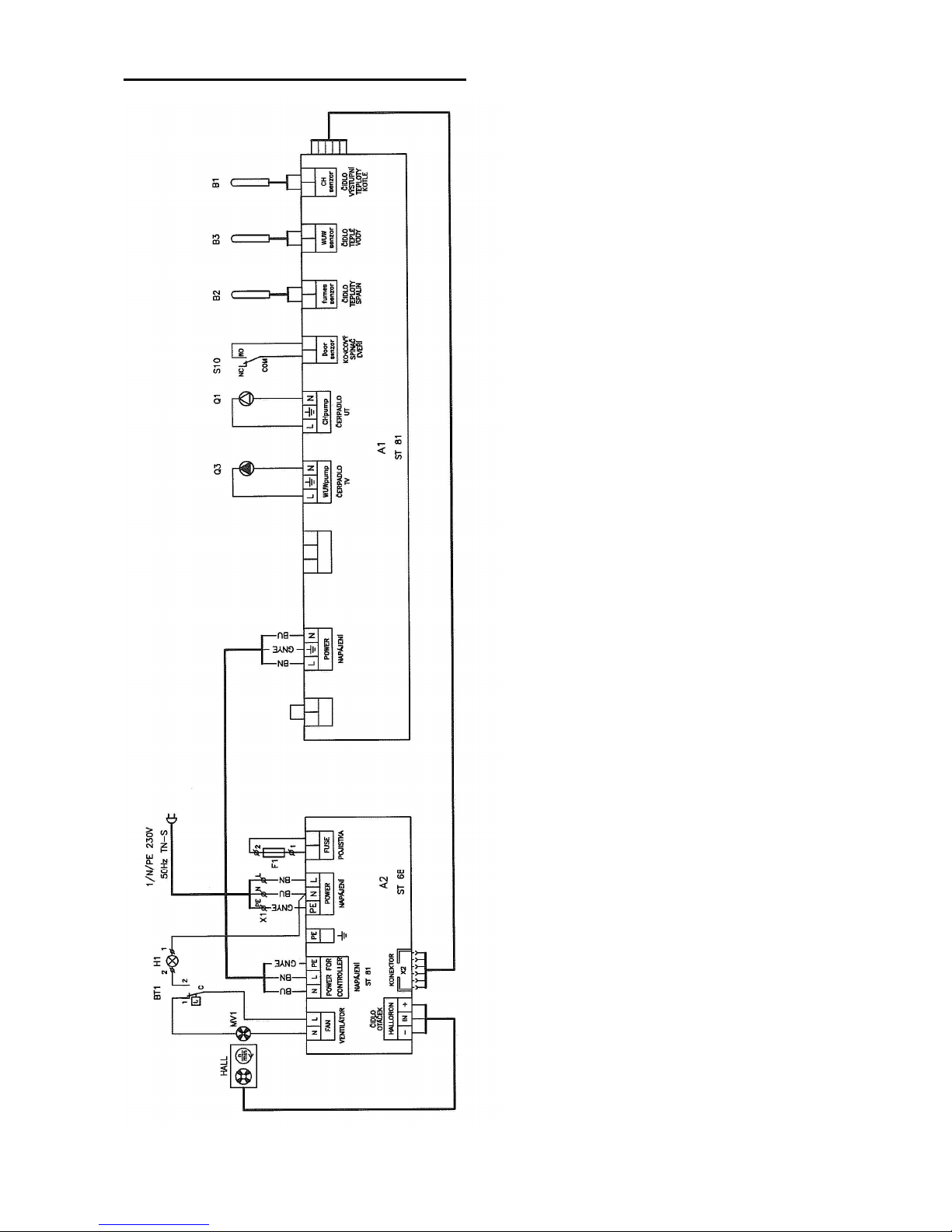
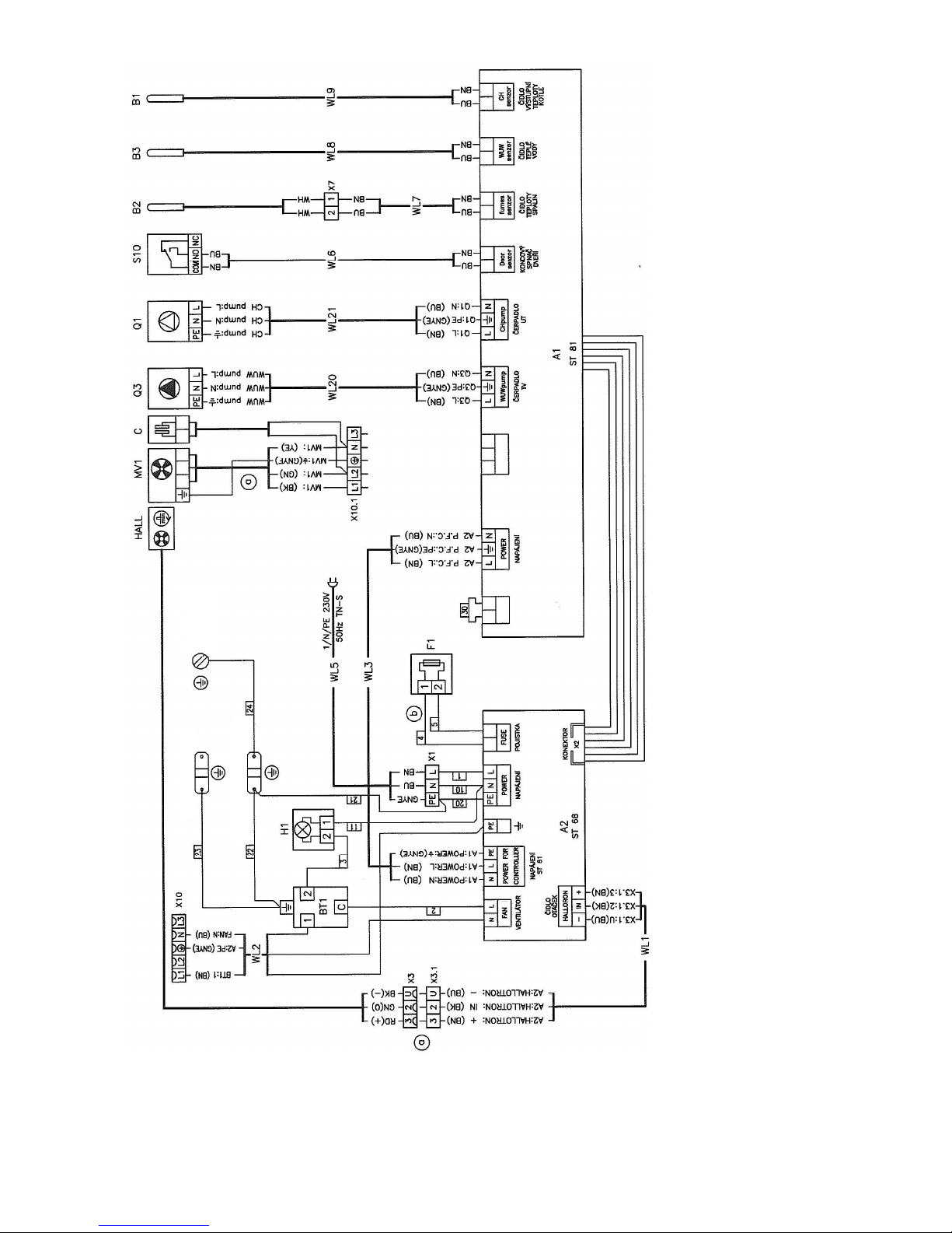
Fig.no. 21 Circuit diagram of connection - boiler Hefaistos P1 E
LEGEND:
A2 MODULE TECH ST 68
ČO SPEED SENSOR MV1
MV1 EXHAUST VENTILATOR
BT1 SAFETY THERMOREGULATOR
H1 SIGNALLING BT1
X1 TERMINAL BOARD OF SUPPLY
X2 CONNECTOR ST 81 DO ST 68
F1 FUSE 6,3 A
A1 CONTROLLER TECH ST 81
Q3 PUMP OF HW (HOT WATER)
Q1 PUMP OF ÚT (CENTRAL HEATING)
S10 LIMIT SWITCH OF STOKING DOOR
B1 BOILER TEMPERATURE SENSOR
B2 FLUE GASES TEMPERATURE SENSOR
B3 HOT WATER TEMPERATURE SENSOR
Wire colour
GNYE green yellow
GN green
YE yellow
RD red
BK black
BN brown
BU blue
Page 31
31
Fig.no. 22 Diagram of connection - boiler Hefaistos P1 E
A1 CONTROLLER TECH ST 81
Q3 PUMP OF HW (HOT WATER)
Q1 PUMP OF ÚT (CENTRAL HEATINGÍ)
S10 LIMIT SWITCH OF STOKING DOOR
B1 BOILER TEMPERATURE SENSOR
B2 FLUE GASES TEMPERATURE SENSOR
B3 HOT WATER TEMPERATURE SENSOR
X10 SOCKET FOR MV1
X10.1 PLUG FOR MV1
LEGEND:
A2 MODULE ST 68
HALL SPEED SENSOR MV1
MV1 EXHAUST VENTILATOR
BT1 SAFETY THERMOREGULATOR
H1 SIGNALLING BT1
X1 TERMINAL BOARD OF SUPPLY
X2 CONNECTOR ST 81 DO ST 68
X3 TERMINAL BOARD HALL
F1 FUSE 6,3 A
Page 32
32
5. Operating manual
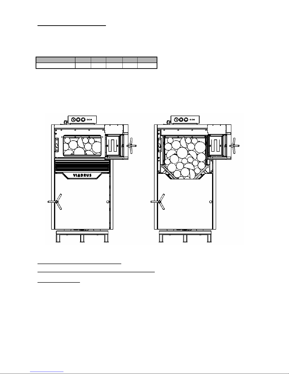
WOOD
Dry split wood logs from 80 to 150 mm.
Length according to Table 3
Tab. No. 3 Length of logs
počet článků
3 4 5 6 7
L mm]
330 470 610 750 890
Calorific value 15 – 17 MJ /kg
Moisture 12 – 20 %
Manufacturer’s warning: Boiler output and its functionality are guaranteed for moisture up to 20%.
When burning the wet wood the boiler does not work in the gasification regime, its output is reduced and
emissions are worse and there occurs the flue gases condensation in the boiler. Consequently the boiler and
chimney service life are shorter.
Fig.no. 23 Location of fuel in the boiler
5.1 Operation of boiler by user
5.1.1 Operation of boiler by user – Hefaistos P1 T
Making a fire (firing)
1. Check the water quantity in the heating system indicated on the thermo-manometer
2. Open the stop valves between boiler and heating system
3. Clean the boiler drum and smoke pathways see chapter 6
4. The flue gases ventilator must not be working
5. Open the throttle valve (choking valve)
6. Insert kindling through the stoking door – dry, smaller wood chips upright on the duct (it is necessary to
pay attention to flue gases flow continuity), then paper and bigger wood chips
7. Ignite the kindling in the feed hopper
8. Close the stoking door
Page 33
33
9. Set the flue gases thermoregulator to 0°C and operating thermo-regulator to operating temperature
(recommended working temperature is 800°C). This will switch on the flue gases ventilator.
10. Let the kindling flare.
11. Close the throttle valve and hold the stoking door ajar, wait approx. 10 seconds before you open it fully
and then fill the whole volume of feed hopper with fuel. Close the stoking door and open the throttle
valve.
Operation
1. Heat the boiler to 80 oC. Set the draught controller to the temperature read on the boiler thermometer.
2. Set the chain of draught controller to the required output, which is at the throttle valve approx.
3 – 50 mm. With a lower air volume the boiler output is reduced. Due to the boiler tarring make sure
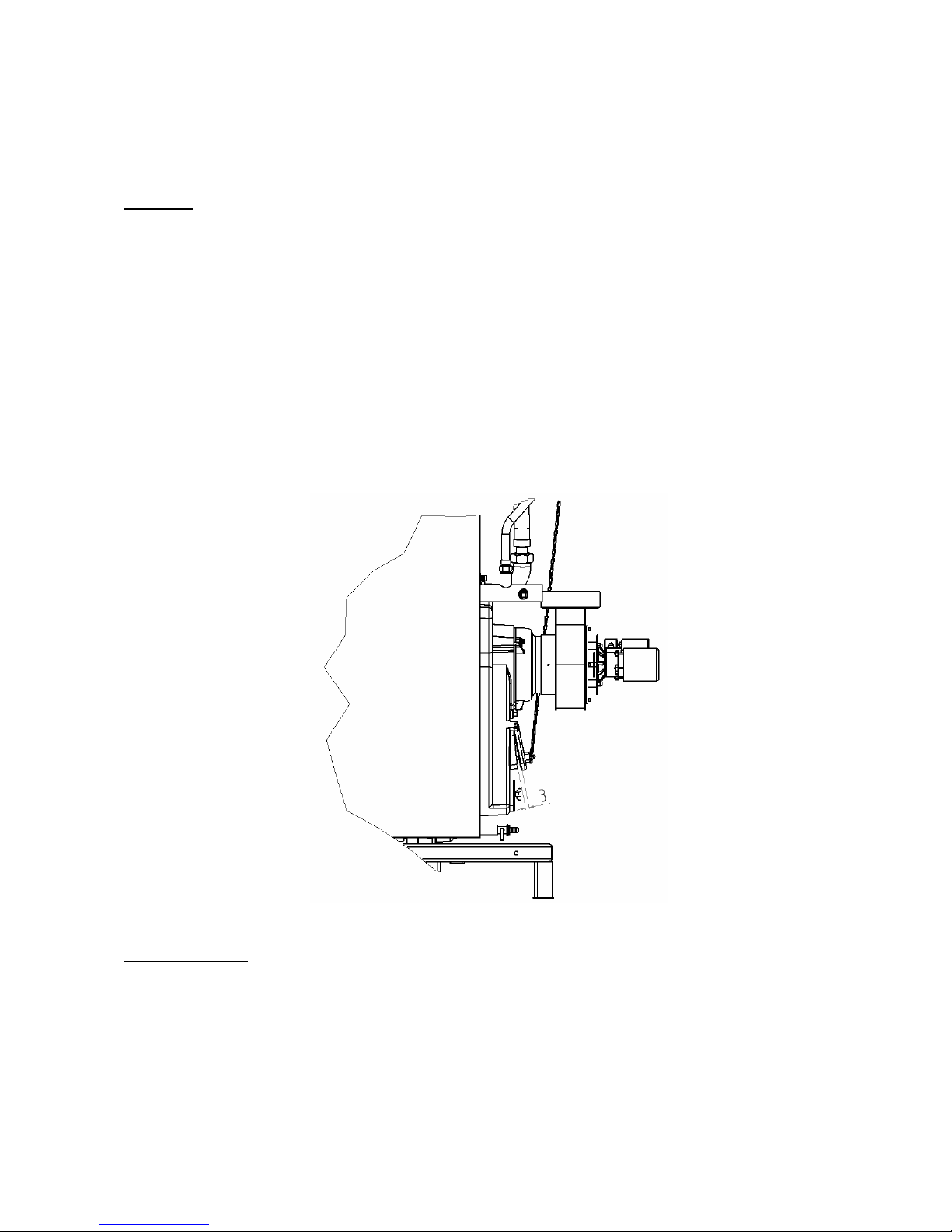
that the throttle valve is never fully closed (it always must be open up to 3 mm by means of the
setscrew of the throttle valve (Fig. no. 24).
3. During the operation the draft controller temperature must be set approx. 5 oC higher than the
temperature set on operating thermoregulator.
4. During operation it is necessary to feed the boiler with fuel according to the combustion intensity and
need of heat. CAUTION! When refilling the fuel close the throttle valve and hold the stoking door
ajar, wait approx. 10 seconds before you open it fully and then fill the whole feed hopper with
fuel. Close the stoking door and open the throttle valve.
5. The boiler working with its full output (2 - 4 stokings) is able to heat up the storage tank volume to
temperature between 80- 90 °C and then we let the boiler burn out. Then we only take heat from storage
tank by means of three-way valve for the duration that corresponds to the size of the storage tanks.
Fig. No. 24 The throttle valve held ajar at 3 mm by means of setscrew
Top-fed operation
The top-fed operation can only be used in winter season due to reduction of boiler service life. At the top-fed
operation the combustion process holds more than 12 hours.
Boiler preparation for the top-fed operation:
1. Replenish the fuel on the glowing layer in the whole volume of the feed hopper.
2. At this operation it is necessary to keep the water temperature 80 – 90 °C. This temperature is achieved
by closing the mixing valve (the ventilator is switched off by the boiler thermoregulator and the boiler
throttle valve is closed).
Page 34

34
5.1.2 Operation of boiler by user – Hefaistos P1 E
User guide for controller ST 81 is delivered separately.
Making a fire
1. Check the water quantity in the heating system indicated on the thermo-manometer.
2. Open the stop valves between boiler and heating system.
3. Clean the boiler drum and smoke pathways see chapter 6.
4. Insert kindling on the nozzle through the stoking door – dry, smaller wood chips upright on the duct (it is
necessary to pay attention to flue gases flow continuity), then paper and bigger wood chips.
5. Ignite the kindling in the feed hopper.
6. Close the stoking door.
7. Connect the controller ST 81 to the electricity mains, switch on (position 1 of the switch). By pressing the
button appears on the display. By the next pressing the button
we make a fire (ventilator is activated).
8. Let the kindling flare.
9. Hold the stoking door ajar, wait approx. 10 seconds before you open it fully and then fill the whole feed
hopper with fuel. Close the stoking door.
10. If the temperature of output water exceeds the set production value of 40 °C within 30 minutes the boiler
ignition and its transfer into automatic mode have been successful. Otherwise, repeat the whole process.
Operation
1. Set the required output boiler temperature of (60 – 85 °C, 80 °C is recommended by the manufacturer).
2. During operation it is necessary to feed the boiler with fuel according to the combustion intensity and
need of heat. CAUTION! When refilling the fuel close hold the stoking door ajar, wait approx. 10
seconds before you open it fully and then fill the whole feed hopper with fuel. Close the stoking
door.
3. The boiler working with its full output (2 - 4 stokings) is able to heat up the storage tank volume to
temperature between 80 – 85 °C and then we let the boiler burn out. Then we only take heat from
storage tank by means of three-way valve for the duration that corresponds to the size of the storage
tanks.
Top-fed operation
The top-fed operation can only be used in winter season due to reduction of boiler service life. At the top-fed
operation the combustion process holds more than 12 hours.
Boiler preparation for the top-fed operation:
1. Replenish the fuel on the glowing layer in the whole volume of the feed hopper.
2. At this operation it is necessary to keep the water temperature 80 – 90 oC. This temperature is achieved
by closing the mixing valve (the ventilator is switched off by the controller)
Ignition
Manual work
Page 35
35
6. Boiler cleaning - maintenance
ATTENTION! Carry out the cleaning exclusively before making fire(firing) and when the combustion
chamber is cold.
1. Remove ashes from the combustion chamber and feed hopper. This must be done before every firing
and once a week in case of top-fed stove operation. Or it must be cleaned as soon as by the visual
control it is indicated that the level of ashes has reached the openings in the back side of the
combustion chamber. The the nozzle and lining are not removed during cleaning.
2. The cleaning of smoke ducts is done depending on the ash deposits on them.
3. It is necessary to put ash into fire resistant bins with lids. At this work it is necessary to use protective
tools and pay attention to personal safety.
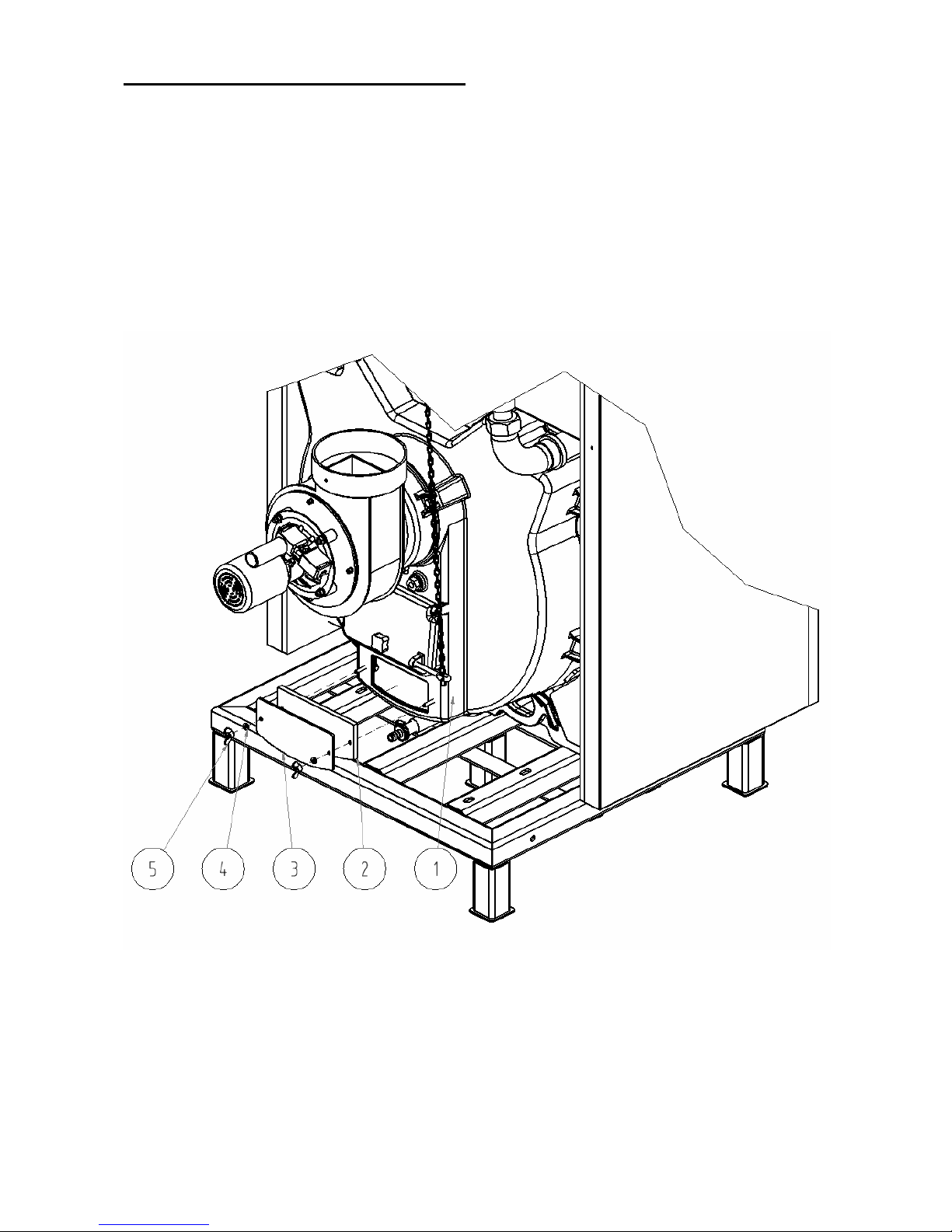
4. Smoke adaptor cleaning according to fig. No 25.
5. At the end of heating season it is necessary to clean smoke drafts of boiler and fan circulation wheel.
6. At the end of heating season clean the door swivel pins of all doors
1 – Smoke adapter
2 – Insulation of cleaning cover of smoke adapter
3 – Cleaning cover of smoke adapter
4 – Hexagon nut M6 with washer 6
Fig.no. 25 Cleaning of the smoke adapter
Page 36
36
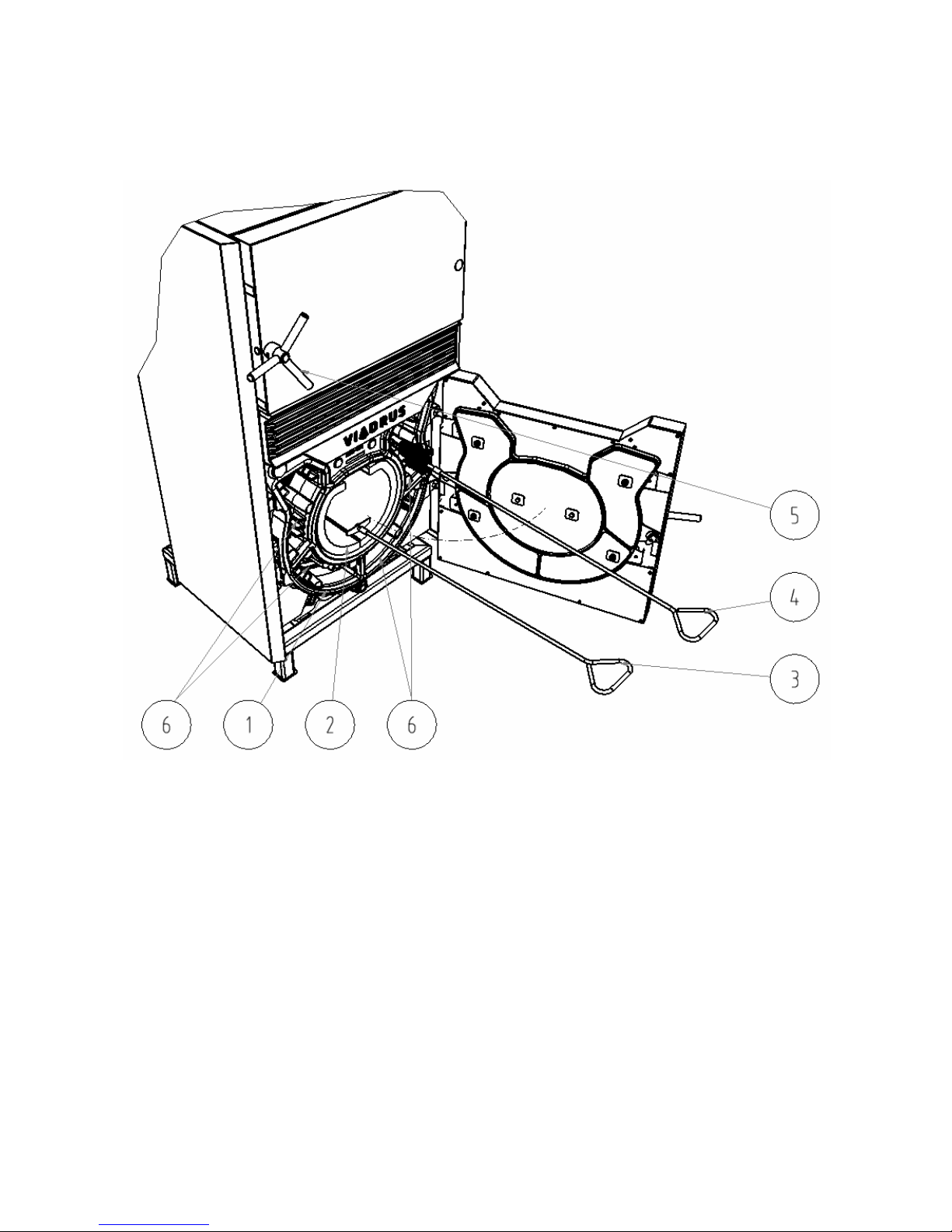
Cleaning of boiler drum and combustion space (see Fig. no. 26):
- Firstly switch on the exhaust ventilator, then open the stoking door and through the slot sweep ashes
into combustion chamber of the boiler drum.
- By means of a cleaner remove ashes and unburnt pieces of fuel from the combustion chamber.
- Clean the boiler drum vent holes by means of a brush. Brush of polyamide can not be used at higher
temperatures (cleaning must be done only at the cold boiler drum)
- Clean (sweep) the internal part of door –remove the ash and soot
1 – Boiler drum
2 – Combustion chamber
3 – Cleaner
4 – Brush
5 – Stoking door
6 – Vent holes of the boiler drum
Fig.no. 26 Cleaning of the boiler drum and combustion chamber
Page 37

37
7. Fault conditions
Fault conditions Cause Remedy
The boiler output is too low Calorific value of fuel is insufficient
fuel moisture is above 20%
Use the prescribed fuel of prescribed
moisture
Clogged or deformed fan propeller Clean the fan propeller or replace it
Reverse fan revolutions Check direction of fan revolutions
Clogged nozzle Clean the nozzle orifice with poker
Operating conditions not observed Check the transport pressure,
temperature of reverse flow
An excessive amount of
condensate in the stoking space
of boiler
Improper or too moist fuel Use prescribed or dry fuel
Low temperature of boiler water Check / increase the minimum boiler
water temperature on the controlling
device and by adjusting the mixing
valve ensure the minimum
temperature 60 ˚C in reverse flow
Flue gases fan does not rotate
or it is too noisy
Attention! Standing fan may
cause incomplete combustion
and formation of tar deposits
Only at standing fan: maximum
temperature of the boiler is reached
No fault has occurred! The boiler is
working properly. The flue gases fan
starts when you open the stoking
door. Too much fuel is loaded.
The fan motor or starting capacitor
are defective
Have the fan or capacitor replaced by
a specialist company.
Propeller of fan is baked Remove tar deposits from the fan
propeller and if a damage is detected
replace the fan propeller
The limit switch of stoking door is in
a wrong position or is defective
Adjust the limit switch of stoking door
or have it replaced by a specialist
company
Page 38

38
8. IMPORTANT NOTICES
1. The boiler only can be used for the purposes that it is destined for.
2. The boiler only can be operated by adults who are made acquainted with this operation manual.
It is not permitted to let the children unattended by adults near the boiler being in operation. It is
not permitted to tamper with boiler in a way, which could endanger operators or eventually
roommates’ health.
3. The boiler is not destined for the use by persons (incl. children) whose physical, sensual or
mental disability or lack of experience and knowledge prevent them from a safe use of the
appliance unless they are supervised or if they were not instructed on the use of appliance by a
person responsible for their safety.
4. Children should be supervised in order to ensure that they do not play with the appliance.
5. If there occurs a danger of combustible vapors or gases that are releasing and penetrating into
the boiler room or when working in a temporary fire or explosion risk (gluing the floorings,
painting works using the combustible paints etc.) the boiler must be well ahead put out of
operation before these works start.
6. It is forbidden to use the flammable liquids for firing the boiler.
7. It is FORBIDDEN to overheat the boiler during its operation.
8. Open the stoking door and ash pan door only by means of plastic handles
9. The ash pan door must not be opened during boiler operation
10. The flammable subjects mustn’t be laid on the boiler or in a distance lower than the safety
distance.
11. The flammable materials must be in a distance at least 1500 mm from the boiler when clearing
ashes from boiler.
12. When operating the boiler at the temperature lower than 60 °C there can appear the retting of
boiler and so called low-temperature corrosion which can reduce the boiler drum service life.
Therefore it is recommended to operate the boiler at temperature 60 °C and higher.
13. After the end of heating season the boiler including the smoke flues and smoke adapters must
be thoroughly cleaned. The swivel pins, smoke flap mechanism and other moving parts of boiler
must be lubricated by applying the graphite grease. Keep the boiler room clean and dry.
14. If the boiler is not in use (e.g. in summer season ) it is necessary to disconnect it from the
electrical power network due to possible damage caused by the atmospheric surge (lightning)!
15. The possible signs of corrosion on the boiler drum are not any defects and do not influence its
function.
16. In case the two-way safety equipment is signalling that boiler has been filled with the water
which does not meet the ČSN 077401 requirements it is necessary to treat the water in the
system so that it again meets this standard requirements.
17. During assembly, installation and operation of the appliance it is necessary to comply with
standards that apply in the relevant country of destination.
If you fail to meet these conditions you cannot requisite the guarantee repairs.
Page 39

39
9. Instructions for disposal of the product after its life time
VIADRUS a.s. is a contracting partner of the firm EKO–KOM a.s. with the client number F00120649.
The packing complies with EN 13427.
We recommend disposing the packing in the following way:
- plastic foil, cardboard cover: use a collection point for waste materials
- metal strapping tape, use a collection point for waste materials
- wooden base, is designated for a single usage and no longer can be used as a product. Its disposal is
subject to Act. 477/2001 Coll. and 185/2001 Coll. as amended.
Because the boiler is constructed from common materials, we recommend disposing the individual parts as
follows:
- the heat exchanger (grey cast-iron), use a collection point for waste materials
- distribution pipes, shell, use a collection point for waste materials
- other metal parts, use a collection point for waste materials
- insulation material ROTAFLEX, through a firm engaged in collection and disposal of waste.
In case that the product has lost its utility properties you can use the taking back service (if this is
introduced). If the originator has declared that it regards the waste it will be handled according to the
legislative provisions valid in the particular country.
10. Warranty and liability for defects
VIADRUS a.s. provides the guarantee:
– for the boiler during 24 months after it was put into operation, but at the most 30 months after it was
dispatched from the production plant.
– for the boiler drum during 5 years after it was dispatched from the production plant.
For a possible complaint the customer is obliged to show the packaging label of the boiler shell. It is
placed on cardboard in which the shell is dispatched.
The user is obliged to entrust a specialist installation company with boiler commissioning and and
with removal of faults only a specialist contractual service accredited by VIADRUS a.s., otherwise the
guarantee for boiler proper function does not apply.
The „Certificate of Hefaistos P1 boiler quality and completeness” after having been filled serves as
the „Guarantee certificate”
The user is obliged to do a regular maintenance on the boiler.
Every defect must be announced immediately after it has been discovered, namely in a written form
and via a telephonic agreement.
In case the above instructions aren’t observed the guarantee provided by the manufacturer will not
be recognized.
The manufacturer reserves the right to make changes within the product innovation that needn’t be
included in this service manual.
The guarantee does not apply to the:
– defects caused by a faulty installation (see chapter 3.5), wrong product operation (see chapter 5.)
and defects caused by wrong maintenance (see chapter 6.)
– product damage caused by transport or other mechanical damage
– defects caused by an inconvenient way of storing
– defects and damage caused by failure to observe the water quality in heating system see chap.
no. 3.2 and 4.1 or using the anti-freeze mixture
– defects caused by breach of instructions mentioned in this service manual
Page 40

40
Information for customer
Packaging edentification
PE Plastic sacks, folie, corrugaled board, iron and plastic fix
line
Assessment reference
Identification od principál materials used. Paper, Polyethylene, iron, wood
Part 1: Summary of assessment
Standard/Report
Assessment requirement
Claim
Note
1.1 Prevention by source
reduction
YES
1.2 Heavy metals and ensure below maximum permitted
levels for components
(CR 13695-1:2000)
YES
1.3 Other
noxious/hazardous
substances
ensure in compliance with
(CR 13695-2:2002, EN 13428:2000) YES
2 Reuse ensure reusability in all terms of the
standard for the functional packaging
unit (EN 13429:2000)
NO
3.1 Recovery by material
recycling
ensure recyclability in all term sof the
standard for the functional packaging
unit (EN 13430:2000)
YES
3.2 Recovery in the form
of energy
ensure that calorific gain is achievable
for the functional packaging unit
(EN 13431:2000)
YES Iron - NO
3.3 Recovery by
composting
ensure compost ability in all terms of
the standard for the functional
packaging unit (EN 13432:2000)
NO
NOTE Conformity with EN 13427 requires affirmative responses to sections 1.1; 1.2; 1.3 and to at
least one of 3.1; 3.2; 3.3. In addition, where a claim of reuse is made section 2 should also record
affirmative responses.
Part 2: Statement of conformity
In the light of the assessment results recorded in part I above, this packaging is claimed to comply
with the requirements of EN 13427:2000.
Page 41

41
Intended for user VIADRUS a.s.
Bezručova 300
735 81 Bohumín
Guarantee certificate and Quality and completeness certificate for
Hefaistos P1 boiler
Boiler serial number ..............................………. Boiler output ...........................................
User (Surname, name) ………………………………………………………………………………………
Address (street, city, postcode) ………………………………………………………………………………………
Tel/Fax ………………………………………………………………………………………
Boiler complies with requirements
EN 303-5 Heating boilers – Part 5: Heating boilers for solid fuels, hand and automatically stocked,
nominal heat output of up to 300 kW – Terminology, requirements, testing and marking
VIADRUS a.s. provides the guarantee:
– for the boiler during 24 months after it was put into operation, but at the most 30 months after the boiler
was dispatched from the production plant
– for the boiler drum during 5 years after it was dispatched from the production plant
Conditions of the warranty:
•
Installation of boiler must be carried out according to "Manual for boiler operation and
installation" by a professional installation company
•
Commissioning must be carried out according to "Manual for boiler operation and installation"
contractual service organization accredited by the manufacturer
•
Faults must be removed by a contractual service organization accredited by the manufacturer
Completeness of the boiler delivery is guaranted by the vendor
Warranty is void if not filled out
User confirms that:
•
the boiler adjusted by the professional installation company did not show any fault during the heating test
•
he received the "Manual for boiler operation and installation " with the duly completed guarantee
certificate and certificate of quality
•
he was acquainted with the operation and maintenance of boiler
……………………………………..
……………………………………..
……………………………………..
Manufacture date Manufacturer’s stamp Controlled by (signature)
……………………………………..
……………………………………...
……………………………………..
Date of installation Installation company
(stamp, signature)
User’s signature
…………………………………….
……………………………………..
……………………………………..
Date of putting into operation Contractual service organization
(stamp, signature)
User’s signature
Page 42

42
Annex to the guarantee certificate for customer- the user
Record of accomplished guarantee and post
-
guarantee repairs and regular product checks
Record
date
Carried out activity
Contractual service
organization
(stamp, signature)
Customer’s
signature
Page 43

43
Intended for the contractual service organisation VIADRUS a.s.
Bezručova 300
735 81 Bohumín
Guarantee certificate and Quality and completeness certificate for
Hefaistos P1 boiler
Boiler serial number ..............................………. Boiler output ...........................................
User (Surname, name) ………………………………………………………………………………………
Address (street, city, postcode) ………………………………………………………………………………………
Tel/Fax ………………………………………………………………………………………
Boiler complies with requirements
EN 303-5 Heating boilers – Part 5: Heating boilers for solid fuels, hand and automatically stocked,
nominal heat output of up to 300 kW – Terminology, requirements, testing and marking
VIADRUS a.s. provides the guarantee:
– for the boiler during 24 months after it was put into operation, but at the most 30 months after the boiler
was dispatched from the production plant
– for the boiler drum during 5 years after it was dispatched from the production plant
Conditions of the warranty:
•
Installation of boiler must be carried out according to "Manual for boiler operation and
installation" by a professional installation company
•
Commissioning must be carried out according to "Manual for boiler operation and installation"
contractual service organization accredited by the manufacturer
•
Faults must be removed by a contractual service organization accredited by the manufacturer
Completeness of the boiler delivery is guaranted by the vendor
Warranty is void if not filled out
User confirms that:
•
the boiler adjusted by the professional installation company did not show any fault during the heating test
•
he received the "Manual for boiler operation and installation " with the duly completed guarantee
certificate and certificate of quality
•
he was acquainted with the operation and maintenance of boiler
……………………………………..
……………………………………..
……………………………………..
Manufacture date Manufacturer’s stamp Controlled by (signature)
……………………………………..
……………………………………...
……………………………………..
Date of installation Installation company
(stamp, signature)
User’s signature
…………………………………….
……………………………………..
……………………………………..
Date of putting into operation Contractual service organization
(stamp, signature)
User’s signature
Page 44

44
Page 45

45
Intended for the manufacturer VIADRUS a.s.
Bezručova 300
735 81 Bohumín
Guarantee certificate and Quality and completeness certificate for
Hefaistos P1 boiler
Boiler serial number ..............................………. Boiler output ...........................................
User (Surname, name) ………………………………………………………………………………………
Address (street, city, postcode) ………………………………………………………………………………………
Tel/Fax ………………………………………………………………………………………
Boiler complies with requirements
EN 303-5 Heating boilers – Part 5: Heating boilers for solid fuels, hand and automatically stocked,
nominal heat output of up to 300 kW – Terminology, requirements, testing and marking
VIADRUS a.s. provides the guarantee:
– for the boiler during 24 months after it was put into operation, but at the most 30 months after the boiler
was dispatched from the production plant
– for the boiler drum during 5 years after it was dispatched from the production plant
Conditions of the warranty:
•
Installation of boiler must be carried out according to "Manual for boiler operation and
installation" by a professional installation company
•
Commissioning must be carried out according to "Manual for boiler operation and installation"
contractual service organization accredited by the manufacturer
•
Faults must be removed by a contractual service organization accredited by the manufacturer
Completeness of the boiler delivery is guaranted by the vendor
Warranty is void if not filled out
User confirms that:
•
the boiler adjusted by the professional installation company did not show any fault during the heating test
•
he received the "Manual for boiler operation and installation " with the duly completed guarantee
certificate and certificate of quality
•
he was acquainted with the operation and maintenance of boiler
……………………………………..
……………………………………..
……………………………………..
Manufacture date Manufacturer’s stamp Controlled by (signature)
……………………………………..
……………………………………...
……………………………………..
Date of installation Installation company
(stamp, signature)
User’s signature
…………………………………….
……………………………………..
……………………………………..
Date of putting into operation Contractual service organization
(stamp, signature)
User’s signature
Page 46

46
Page 47

47
Page 48
48
Update Date 42/2012 – GB
 Loading...