

Page 1

VIADRUS G 90
Manual for assembly of boiler
GB_2017_23 ND
GB_ _ND2015_26
Page 2

Contents
1 Boiler technical data .................................................................................................................................................................................... 3
2 Boiler Installation ......................................................................................................................................................................................... 5
2.1 Pedestal Installation ............................................................................................................................................................................... 5
2.2 Binding of the Boiler Body ...................................................................................................................................................................... 5
2.3 Installation of tubing, fittings and a well .................................................................................................................................................. 6
2.4 Installation of a partitioned horizontal draught interrupter ....................................................................................................................... 7
2.5 Installation of burner .............................................................................................................................................................................. 7
2.6 Thermal insulation of the boiler body...................................................................................................................................................... 7
2.7 Installation of the gas armature .............................................................................................................................................................. 8
2.8 Boiler casing installation ........................................................................................................................................................................ 8
3 Electrical Panel installation .......................................................................................................................................................................... 9
3.1 Installation of the Distributing Box .......................................................................................................................................................... 9
3.1.1 Electrical Panel installation ......................................................................................................................................................... 10
3.1.2 Completion of the Electrical Installation ...................................................................................................................................... 10
3.2 Version 10, 12, 15 links automatics HONEYWELL, valve HONEYWELL ............................................................................................. 11
3.2.1 Installation of the Distributing Box .............................................................................................................................................. 11
3.2.2 Electrical Panel installation ......................................................................................................................................................... 11
3.2.3 Completion of the Electrical Installation ...................................................................................................................................... 12
3.3 Version 10, 12, 15 links automatics HONEYWELL, valve DUNGS ...................................................................................................... 12
3.3.1 Installation of the Distributing Box .............................................................................................................................................. 12
3.3.2 Electrical Panel installation ......................................................................................................................................................... 13
3.3.3 Completion of the Electrical Installation ...................................................................................................................................... 13
4 Electrical connections flow sheet ............................................................................................................................................................... 14
page
2
Page 3

-
1
-
1
-3
-3
-
3
1 Boiler technical data
Tab. №. 1 Dimensions, service temperatures and electric parameters of the boiler
Number of sections pc 8 10 12 15
Appliance category I2H
Weight kg 242 339 399 489
Water space volume l 27,7 34,3 40,9 50,8
Diameter of smoke socket mm 200 200 225 250
Boiler overall dimensions - depth mm 995 1155 1315 1555
Max. water operating overpressure kPa (bar) 400 (4)
Min. water operating overpressure kPa (bar) 30 (0,3)
Testing water overpressure kPa (bar) 800 (8)
Max. heating water operating temperature °C 85
Min. return water temperature °C 50
Input gas overpressure mbar 20
Noise level dB Does not exceed the 55 dB (A) level
Chimney draught mbar Minimum 0,025
Boiler connections - heating water Js 6/4"
Connecting voltage 1/N/PE 230 V AC 50 Hz TN-S
Electric input W 50
Electric protection IP 40
Tab. №. 2 Thermal parameters of boiler
(heating value 33,99 MJ. m-3, gas temperature 15°C and bar. air pressure 1013,25 mbar)
Number of sections pcs 8 10 12 15
Rated thermal output max. kW 64 80 96 120
Rated thermal output min. kW 49 56 67 84
Rated thermal output max kW 71 87 105 127
Rated thermal output min kW 55 61 73 94
Volume gas flow at the maximum thermal output m3.h
Volume gas flow at the minimum thermal output m3.h
Efficiency at the maximum thermal output
Efficiency at the minimum thermal output
Temperature of the combustion gases after the draught diverter at the
maximum thermal output
Temperature of the combustion gases after the draught diverter at the
minimum thermal output
Volume of dry combustion gases actual at the maximum thermal output m3.m
Volume of dry combustion gases actual at the minimum thermal output m3.m
Emission values - CO mg.m
- NOx mg./kWh 33 33 27 23
Grade of NOx grade V
Nozzle diameter
Honeywell VR 4601 and VR 4605 valves
Informative gas pressure at the nozzle for the nominative output at the
maximum thermal output
Informative gas pressure at the nozzle for the nominative output at the
minimum thermal output
Dungs MB – ZRDLE 412 valve
Informative gas pressure at the nozzle for the nominative output at the
maximum thermal output
Informative gas pressure at the nozzle for the nominative output at the
minimum thermal output
- width x height mm 878,5 x 1160 941x1160
- return water Js 6/4"
- gas Js 1/2" 1“
7,16 9,25 11,32 13,61
5,56 6,5 7,85 10,05
%
%
91 92
89 92
°C 122 129 114 118
°C 98 95 95 88
20,18 15,8 21,6 18,13
23,63 20,1 24,8 23,6
5 6 8 7
mm 2,42
mbar 15 14,8 14,5 14
mbar 9 7,6 7,5 7,5
mbar - 13,8
mbar - 7
3
Page 4

Number of sections 8 10 12 15
L [mm] 995 1155 1315 1555
L1 [mm] 815 975 1135 1375
A [mm] 878,5 941 941 941
D [mm] 200 200 225 250
Gas inlet
4
Page 5

2 Boiler Installation
Important Cautions:
Boiler Installation may be carried out exclusively by contractual arrangement with approved and manufacturer’s
accredited service organization
Connections for heating and return water are situated always on one side of the boiler, right or left, in conformance to
the space disposition of the boiler room.
• Installation of the gas manifold to pedestal equipped with cover sheet metal for combustion chamber
• Fastening boiler body to the pedestal.
• Installation of the horizontal draught interrupter onto the boiler body
• Installation of tubing for heating and return water with distributor pipe
• Burner installation
• Connecting gas armature with the burner
• Thermal insulation of the boiler body
• Partial jacketing of the boiler
• Mounting the electrical panel
• Carrying out the electrical installation
• Electrical conduit connections, placement of sensors, affixing manometer detecting sensor
• Electrical interconnection of the gas manifold
• Completion of the boiler jacketing
2.1 Pedestal Installation
List of parts needed
1 pc of boiler pedestal
1 pc cover for the combustion chamber
Installation procedure
Position the cover sheet metal over future combustion
chamber on the pedestal
cover sheet
metal – burning
space
boiler pedestal
2.2 Binding of the Boiler Body
Using 800 kPa (8 bar) testing overpressure over at least 15 minutes, test the integrity of the boiler assembly. Visual control to be
carried out AFTER this test period.
List of parts needed
Boiler links
1 pc boiler link left
1 pc boiler link right
8, 10; 13 pc of middle links, number is determined by size
18, 22; 28 pc boiler inserts – as per boiler size
3 pc anchoring screws M 10 x L
1 pc mounting brace
2 pcs cover sheet metal lid
of the boiler
(as per respective size)
Installation procedure
1. All sockets and drilled socket holes in boiler links must be thoroughly cleaned from
conservation agents leftovers.
2. Outer edges of the openings to be removed by a half-circular file.
3. Paint the holes and sockets by oil or varnish paint.
4. Deposit boiler glue paste on prepared cleanly grinded off surfaces of the links joint
5. Tightening of the boiler body parts to be done on the prepared pedestal with cover sheet
metal installed such that the combustion chamber is directed towards the front part of the
pedestal Inserts to be evenly deposited into the socket holes, using a light tap of the rubber
or wooden mallet.
6. Affix the boiler link over the protruding inserts, tap in place and carry out binding of the link
with aid of the bonding tools; this step to be repeated until final size is tightened together
Tightening is to be done by hydraulic or manual fastening clamps
7. It is not permitted to tighten more than one link at a time.
8. Boiler links to be pulled together evenly both on the upper as well as lower level.
Always keep ensuring that the links are installed parallel to each other. Using anchoring
bolts, secure in place. Anchor nuts should be tightened only lightly (when tapping the bolt by
a metal device, the sound must never be jingly). This is to allow dilatation of the boiler body
when thermally stressed.
5
6 pc of washer Ø 10
1 pc of completed boiler pedestal
4 pc of bolt M 8
4 pc of nut M 8
4 pc of washer Ø 8
6 pc of nut M 10
Oil or varnish colour for painting of the boiler inserts
Boiler binder sealant
Page 6
9. Ensure that the sealant paste supplied by the manufacturer is providing a perfect seal.
10. Boiler body is to be fastened to the pedestal, using 4 pc of M8 x 25 bolts, M 8 nuts and washers Ø 8.
11. Boiler sealant then should be liberally and thoroughly applied to the contact surface between the protective pedestal cover and the boiler
body; excess glue to be removed.
12. Place plugging blanks to the openings in the bottom part of outer links and ensure good seal by using a silicone sealant supplied by the
manufacturer
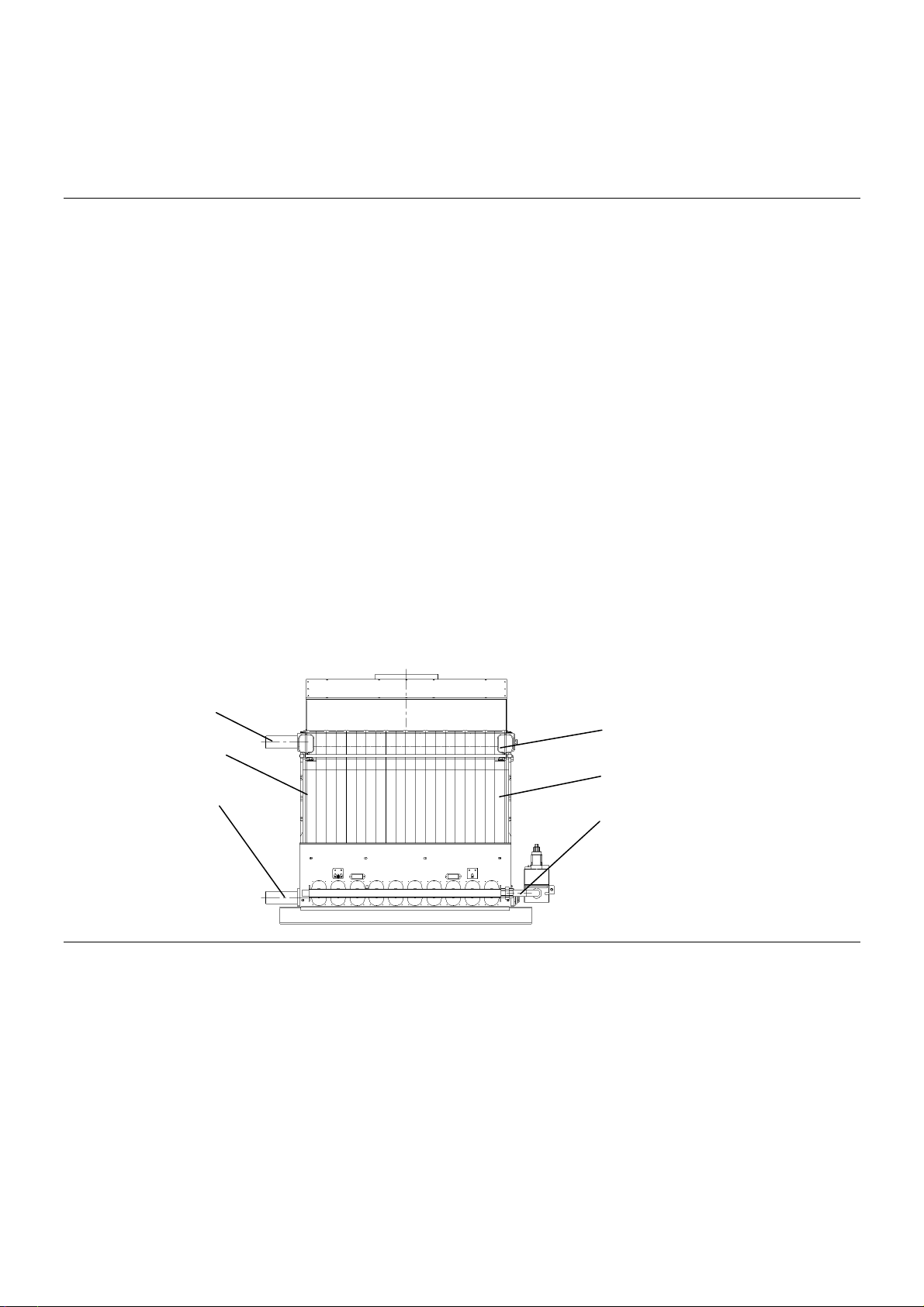
2.3 Installation of tubing, fittings and a well
List of parts needed
2 pcs of drain taps ID1/2”
1 pc reducer G 1 1/2”/G 1”
1 pc plugging stopper with external thread 1”
1 pc attachable check valve with a manometer G 1/2
1 pc four-seat well G 1/2”
1 pc stopper plug G 1 1/2”
Right version
• Mounting of left end section:
- To the upper orifice G 1 1/2” mount tube Js 1 1/2“ for heating water.
- To the lower orifice G 1 1/2” after mounting the distribution tube mount the reverse water tube Js 1 ½“ (plug welded on the tube
must be directed upwards).
• Mounting of right end section:
- To the upper orifice G 1 1/2” mount the reduction G 1 1/2" to G ½“.
- To the reduction G 1 1/2"/G 1/2 mount the four-place reservoir G ½“.
- To the thread G ½“ under the reduction G 11/2“ mount the check valve of the manometer.
- To the lower orifice G 1 1/2" mount a complete distribution tube.
Into the threads G ½“ in the lower part of both end sections screw the outlet and inlet cocks.
Screw the cover sheet of the combustion chamber to the backside of the boiler drum by using 4 pc screws M6 with washers and nuts
Assembly of distribution tube (right)
Insert the plastic distribution tube into plug G 1“ with the opposite end than the rectangular cut out on the distribution tube, then insert it into
reduction G 1 1/2“/ 1/2“ a screw together. Insert the whole set of the distribution tube (with plug and reduction) into the do lower distance orifice
of the right end section and screw up (plug welded on the tube must be directed upwards).
1 pc of complete distributing pipe assembled with a
bent tube for return water (left or right styling)
1 pc tubing for return water
4 pcs screw M6
2 pc of washer Ø 6
2 pc of nut M6
2 pcs of rosette washer 6
Heating water
tube Js 11/2“
left end section
reverse water
tube Js 11/2“
reduction G11/2“/G1/2“
right end section
distribution tube with a
plug G1“ and reduction
G11/2“/G1“
Installation of heating water and reverse water tubes (right version)
Left version
• Mounting of the right end section:
- To the upper orifice G 1 1/2” mount tube Js 1 1/2“ for heating water.
- To the lower orifice G 1 1/2” after mounting the distribution tube mount the reverse water tube Js 1 ½“ (plug welded on the tube must be
directed upwards).
• Mounting of the left end section:
- To the upper orifice G 1 1/2” mount the reduction G 1 1/2" to G ½“.
- To the reduction G 1 1/2"/G 1/2" mount the four-place reservoir G ½“.
- To the thread G 1/2“ under the reduction G 11/2“ mount the check valve of the manometer.
- To the lower orifice G 1 1/2" mount a complete distribution tube.
Into the threads G 1/2“ in the lower part of both end sections screw the outlet and inlet cocks.
Screw the cover sheet of the combustion chamber to the backside of the boiler drum by using 4 pc screws M6 with washers and nuts
6
Page 7

Assembly of distribution tube (left)
Insert the plastic distribution tube into plug G 1“ with the opposite end than the rectangular cut out on the distribution tube, then insert it into
reduction G 1 1/2“/ 1/2“ a screw together. Insert the whole set of the distribution tube (with plug and reduction) into the do lower distance orifice
of the right end section and screw up (plug welded on the tube must be directed upwards).
2.4 Installation of a partitioned horizontal draught interrupter
List of parts needed
1 pc horizontal draught interrupter – front part
1 pc horizontal draught interrupter – rear part
4 pc screws M8 with nuts and washers
21 pc of sheet metal screws 4.8 (sizes with 10, 12 links)
Installation procedure
1. Cover the top joining surface of the boiler body with silicone sealant/binder
2. Fasten the horizontal draught interrupter – front part
3. Put the supports on the bends of the horizontal draught diverter (the bend of supports is directed downwards).
4. Secure it to the boiler body using 4 bolts M8 with nuts and washers
5. After the boiler is completely covered with its jacket, affix the horizontal draught interrupter – rear part onthe horizontal interrupter – front
part, and secure with aid of requisite number of sheet metal screws
Note: at the 8-section the horizontal draught diverter is compact.
Front part
Support
Installation of the horizontal draught interrupter
23 pc of sheet metal screws 4.8
(size with 15 links)
2 pc support
Silicone sealant/binder (from manufacturer)
Rear part
Protecting
metal sheet
2.5 Installation of burner
List of parts needed
1 pc burner complete assembly
4 pcs screw M6
4 pc of washer Ø 6
4 pc of nut M6
Boiler binder sealant
Installation procedure
1. Combustion chamber of the boiler’s body is to be cleaned up from eventual impurities.
2. Put the boiler cement on the contact surface between the burner insulation and boiler drum.
3. Burner is to be inserted into the combustion chamber of the boiler’s body and secured using 4 screws M6 with nuts and washers.
4. Mount the lighting burner and watching electrode to the burner plate with gas distributor and nozzles (on one side of the burner gas
distributor there is mounted a blind flange. The opposite end is prepared for connection of a complete gas fitting. Remount the blind flange
from the right or left side depending on the selected side of gas connection).
2.6 Thermal insulation of the boiler body
List of parts needed
1 pc tightening sling with a clasp
1 pc insulation Rotaflex L (2900, 3200, 3650 mm) as per size of the boiler
Installation procedure
1. Wrap the insulation over the perimeter of the boiler vessel.
2. Remaining insulation to be utilized for upper part of the horizontal draught interrupter before the upper lid of the jacket is secured.
3. Cut out the insulation from: intake and discharge of the heating water, sensor well, check valve and burner places.
7
Page 8

2.7 Installation of the gas armature
List of parts needed
1 gas armature assembly (twins of gas valves HONEYWELL or a gas manifold DUNGS ZRDLE 412 with attached gas branch)
1 pc gas intake tube leading to the pilot from left (right)
Installation procedure
1. Mount the gas armature over the flange from the side opposite to that where the gas distributor is blanked out, in keeping the selected
direction (from left or right)
2. Interconnect the pilot with the gas armature, using the gas intake tubing provided.
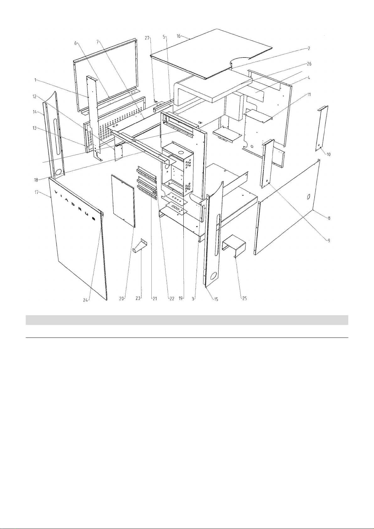
2.8 Boiler casing installation
List of parts needed
1pc casing side part A right (1)
1pc casing side part A right (2)
1pc casing side part B right (3)
1pc casing side part B right (4)
I pc jacket console (5)
1 pc front part of the jacket (6)
1 pc front part of the jacket (7)
1pc rear casing part bottom (8)
1 pc side portion left of the rear part - cover (9)
1 pc side portion left of the rear part - cover (10)
2 pcs braces (11)
2 pcs cover (12)
1 pc burner cover (13)
1 pc side part of front jacket portion left (14)
1 pc side part of front jacket portion left (15)
1 pc top part of the jacket (16)
1 pc front part of the jacket with sign (17)
1 pc electrical panel console (18)
Installation procedure
1. When looking at the burner left side of the support fasten at the back the side part of the shell B left (4) by means of one inbus screw
M5.
2. To the rear side of the side part of the shell B left (4) screw up the backside of the shell lower (8) by means of screws M 5 – do not
tighten up.
3. When looking at the burner right side of the support fasten at the back the side part of the shell B right (3) by means of one inbus screw
M5 and screw together with the rear part of the shell lower (8) by means of screws M5
4. When looking at the burner left side of the support in front fasten the side part of shell A left (2) into the riveting nut by means of 1 screw
M5 and screw together by means of self-drilling screws 4,2 with already fastened side part B left (4).
5. When looking at the burner right side of the support in front fasten side part of shell A right (1) into the riveting nut by means of 1 screw
M5 and screw together by means of self-drilling screws with already fastened side part B right (3).
6. The screwed together side parts join with the shell bracket (5) by means of two screws M5.
7. By means of 8 self-drilling screws screw the bracket of the front part of the shell (7) to the lower bend of the front part of the shell (6).
Then put it through the side parts of the shell A,B in the front part and hang it in the upper part through the shell bracket (5) and screw
together with the side parts of shell A (1, 2).
8. In the backside at the top put the side part of the shell left and right of the rear part of the shell (9,10) and screw the rear part of the shell
to the lower part (8) by means of 4 screws to the sheet 4,2 and to the side parts by means of screws M5 – do not tighten up.
9. On the side part of the shell where there is planned the mounting of an electro-panel we loosen up the inbus screws M5 on the right and
left side. We insert underneath the side part of the front part of the shell left and right and we again screw up by means of screws M5.
We mind that the edges of the bends are at the same level as the others. Then in the upper part we screw up the bracket of the electropanel (18) by means of 2 screws M5 and screw it together with the side parts of the front part of the shell (14, 15).
10. By means of left and right reinforcements (23, 24) reinforce the side parts of the front part of the shell (14, 15) with the side parts A, B.
11. Screw the front mounting plate from the side of the boiler drum above the switch box by means of 2 self-drilling screws 4,2.
12. Screw the rear mounting plate from the opposite side of the boiler by means of 2 self-drilling screws 4,2.
13. Put the covers (12) on the protruding screws of the burner plate from both sides and tighten four nuts M6 with washers.
14. Mount 4 shape springs in orifices in the side parts from the side of burner. Mount 4 shape cones in the burner cover (13). Put on the
burner cover on the shape springs.
15. Put on the upper part of the shell (16) and the front part of the shell (17).
1 pc switch (distribution) box (19)
1 pc switch (distribution) box cover (20)
1 pc assembly console large (21)
1 pc assembly console small (22)
1 pc reinforcement right (23)
1 pc reinforcement left (24)
1 pc support (25)
1 pc insulation of the boiler drum
and horizontal draught interrupter (26)
2 pc fastening bracket (27)
1 pc mounting plate front (28)
1 pc mounting plate rear (29)
12 pcs taper plug
8 pcs gussets
17 pcs screw M5x10
28 pcs screw to sheet metal 4,2x9
2 pcs screw M4x4
9 pcs inbus screw 2,9x16
8
Page 9
28
29
3 Electrical Panel installation
3.1 Installation of the Distributing Box
List of parts needed
1 pc Switch box
1 pc Installation Console (large)
1 pc Installation Console (small)
16 pcs Screw AM 5 x 8 mm
16 pcs Rosette washer Ø 5,2 mm
1 pc Cover plate HONEYWELL
2 pcs Rubber bushing Ø 13 mm
10 pcs Entry bushing PG 9
8 pcs Entry Bushing PG 11
1 pc Fuse box
1 pc Tube fuse 4 A
Installation procedure
1. With aid of 8 screws M5 with rosette washers, the installation console is to be mounted on a side portion of the jacket left cover B. Above,
a smaller console shall be installed to assist in securing the terminals.
2. Sequentially, 8 pc of entry bushing PG11,to be mounted on the distribution box. Then, 8 pc of entry bushings PG9, end pieces of cover
tubes PG39 a PG48, a fuse box with 4A fuse, and two screws M5 are used to secure the cover HONEYWELL, containing already
installed from left two bushings PG9 and two rubber bushings Ø 13 mm.
3. The box so equipped is to be mounted on a side part B left using four screws M5.
4. At the box’s bottom on left, using two M4 screws, the ionization automatics HONEYWELL is to be fastened such, that the connector
leading to the igniter is orientated right down.
5. The terminal X10 with conduits and suppression component Z1 is fastened into the lower portion of the installation console (Large) Antijamming element is to be fastened using the fastener band to the console.
6. Following the schematics, line wires 1, 2 are connected to the fuse box.
9
1 pc End piece of the tube PG 48
1 pc Nut of the end piece of the tube PG 48
600 mm Protection tube PG 48
1 pc End piece of the tube PG 36
1 pc Nut of the end piece of the tube PG 36
450 mm Protection tube PG 36
1 pc Ionization automatics
HONEYWELL S 4563B1011
2 pcs Screw AM 4 x 8
1 pc Bundle of conduits
Page 10

7. Further line wires No.10,11,15,22,,27,28,45 and 55 are connected to the ionization automatics.
8. The remaining line wires put through the end piece of the protective tube PG48, and then the actual tube is inserted over the conductors.
9. Line wire 90, connected to the igniting electrode, is to be inserted through the rubber bushing Ø 13.
10. Conduit no. 90, connected to the guardian electrode, is to be inserted through the rubber bushing Ø 13.
11. Conduit no. 92 to burner is to be iserted through bushing PG9.
12. Cable W1 is to be inserted through the last bushing PG9 and its conduits are to be connected in the distributing box as follows:
Black J3: 2
Brown X10: 23
Grey X10: 24
Blue X10: 5
Green-yellow Terminal plate console
13. The cable W1 opposite end is to be connected to X6 gas valve connection outlet as follows:
Black X6: L1
Brown X6: L2
Grey X6: L3
Blue X6: N
Green-yellow PE
14. The outlet X6 before covering is to be affixed using two self-cutting screws 2,9x19 onto a side piece under the distributing box. Cover it
after its affixing.
15. Into the X6* gas valve connector are to be connected gas valve Y1 - X8.1 outlet cables.
16. (small burner+1
st
step) and X8.2 (High-Low coil) as follows:
X8.1 – Green - Yellow X6*: PE
Blue X6*: N
Brown 6*: L2
Black X6*: L1
X8.2 – Green - Yellow X6*: PE
Blue X6*: N
Brown X6*: L3
3.1.1 Electrical Panel installation
List of parts needed
1 pc Power module preconnected
1 pc End piece of the tube PG 48
1 pc Nut of the end piece of the tube PG 48
1 pc End piece of the tube PG 36
1 pc Nut of the end piece of the tube PG 36
Installation procedure
1. End pieces of the tubes PG36 and PG48 are to be fastened into the electrical panel console
2. Wires are to be put through the end piece PG48, and the cover tube secured
3. Following the connection schematics, instruments are to be connected within the power network module:
BT2 – c.n.. 13,14,18,56
BT1 – c.n. 15,17,18,57
BT4 – c.n. 7,8,58
S1 – c.n. 2,3
H1 – c.n. 40
H2 – c.n. 19.40
H3 – c.n. 29.41
S3 – c.n. 27
S2 – c.n. 24,25
F2 – c.n. 6,7
4. Green and yellow wire no.59 connect to the electrical panel console
5. Green-yellow wire no.70 will connect the panel console with the Boiler body
6. Cable cover tube PG36 should be fastened into end pieces situated on the Distribution Box and the Electrical Panel Console
3.1.2 Completion of the Electrical Installation
List of parts needed
1 pc Electrical Panel
2 pcs Blank L&G large
1 pc L&G small plug with thermomanometer
1 pc Flexo cable
Installation procedure
1. The sensing capillary of the instruments are to be inserted into appropriate wells, the manometer sensor then screwed into the return
valve.
2. The electrical panel is to be mounted on the electrical panel console Insert into the electrical panel opening sequentially: the power
module, two large blanks L & G, and a small blank L & G with a thermo-manometer. Using the bushing PG11, put through the incoming
power cord into the distribution box and connect it to the terminal X10:
Green-yellow X10: PE
Blue X10: N
Brown X10: U
3. Sockets X8.1 and X8.2 to be connected to the gas valve.
4. Connector X6* to be connected to X6 socket.
10
Page 11

3.2 Version 10, 12, 15 links automatics HONEYWELL, valve HONEYWELL
3.2.1 Installation of the Distributing Box
List of parts needed
1 pc Switch box
1 pc Installation Console (large)
1 pc Installation Console (small)
16 pcs Screw AM5x8mm
16 pcs Rosette washer Ø 5,2mm
1 pc Cover plate HONEYWELL
2 pcs Rubber bushing Ø 13 mm
2 pcs Entry bushing PG 9
10 pcs Entry Bushing PG11
1 pc Fuse box
1 pc Tube fuse 4A
Installation procedure
1. With aid of 8 screws M5 with rosette washers, the installation console is to be mounted on a side portion of the jacket left cover B. Above,
a smaller console shall be installed to assist in securing the terminals
2. Sequentially, 8 pc of entry bushing PG11,to be mounted on the distribution box. Then, 8 pc of entry bushings PG9, end pieces of cover
tubes PG39 a PG48, a fuse box with 4A fuse, and two screws M5 are used to secure the cover HONEYWELL, containing already installed
from left two bushings PG9 and two rubber bushings Ø 13 mm.
3. The box so equipped is to be mounted on a side part B left using four screws M5.
4. At the box’s bottom on left, using two M4 screws, the ionization automatics HONEYWELL is to be fastened such, that the connector
leading to the igniter is orientated right down.
5. The terminal X10 with conduits and suppression component Z1 is fastened into the lower portion of the installation console (Large) Antijamming element is to be fastened using the fastener band to the console.
6. Following the schematics, line wires 1, 2 are connected to the fuse box
7. Further line wires No.10,11,15,22,,27,28,45 and 55 are connected to the ionization automatics.
8. The remaining line wires put through the end piece of the protective tube PG48, and then the actual tube is inserted over the conductors
9. Line wire 90, connected to the igniting electrode, is to be inserted through the rubber bushing Ø 13.
10. Conduit no. 90, connected to the guardian electrode, is to be inserted through the rubber bushing Ø 13.
11. Conduit no. 92 to burner is to be iserted through bushing PG9.
12. Cable W1 is to be inserted through the last bushing PG9 and its conduits are to be connected in the distributing box as follows:
Black J3: 2
Brown X10: 23
Grey X10: 24
Blue X10: 5
Green-yellow Terminal plate console
13. The cable W1 opposite end is to be connected to X6 gas valve connection outlet as follows:
Black X6: L1
Brown X6: L2
Grey X6: L3
Blue X6: N
Green-yellow PE
14. The outlet X6 before covering is to be affixed using two self-cutting screws 2,9x19 onto a side piece under the distributing box. Cover it
after its affixing.
15. Into the X6* gas valve connector are to be connected gas valve Y1 – X8.1 outlet cables.
16. (small burner+1st step) and X8.2 (High-Low coil) as follows:
X8.1 – Green – Yellow X6*: PE
Blue X6*: N
Brown 6*: L2
Black X6*: L1
X8.2 – Green – Yellow X6*: PE
Blue X6*: N
Brown X6*: L3
17. Similarly are to be connected cable conduits of the Gas valve Y2 – X9.1 (1st step) and X9.2 (High-Low coil).
1 pc End piece of the tube PG 48
1 pc Nut of the end piece of the tube PG 48
600 mm Protection tube PG 48
1 pc End piece of the tube PG 36
1 pc Nut of the end piece of the tube PG 36
450 mm Protection tube PG 36
1 pc Ionization automatics HONEYWELL
S 4563B1011
2 pcs Screw AM4 x 8
1 pc Bundle of conduits
3.2.2 Electrical Panel installation
List of parts needed
1 pc Power module preconnected
1 pc End piece of the tube PG 48
1 pc Nut of the end piece of the tube PG 48
Installation procedure
1. End pieces of the tubes PG36 and PG48 are to be fastened into the electrical panel console
2. Wires are to be put through the end piece PG48, and the cover tube secured
3. Following the connection schematics, instruments are to be connected within the power network module:
BT2 – c.n.. 13,14,18,56
BT1 – c.n. 15,17,18,57
BT4 – c.n. 7,8,58
S1 - c.n. 2,3
H1 - c.n. 40
11
1 pc End piece of the tube PG 36
1 pc Nut of the end piece of the tube PG 36
Page 12

H2 - c.n. 19.40
H3 - c.n. 29.41
S3 - c.n. 27
S2 - c.n. 24,25
F2 - c.n. 6,7
4. Green and yellow wire no.59 connect to the electrical panel console
5. Green-yellow wire no.70 will connect the panel console with the Boiler body
6. Cable cover tube PG36 should be fastened into end pieces situated on the Distribution Box and the Electrical Panel Console
3.2.3 Completion of the Electrical Installation
List of parts needed
1 pc Electrical Panel
2 pc Blank L&G large
Installation procedure
1. The sensing capillary of the instruments are to be inserted into appropriate wells, the manometer sensor then screwed into the return
valve.
2. The electrical panel is to be mounted on the electrical panel console Insert into the electrical panel opening sequentially: the power
module, two large blanks L & G, and a small blank L & G with a thermo-manometer. Using the bushing PG11, put through the incoming
power cord into the distribution box and connect it to the terminal X10
Green-yellow X10: PE
Blue X10: N
Brown X10: U
3. Sockets X8.1 and X8.2 to be connected to the gas valve.
4. Sockets X9.1 and X9.2 to be connected to the gas valve.
5. Connector X6* to be connected to X6 socket.
6. Connector X7* to be connected to X7 socket.
1 pc L&G small plug with thermomanometer
1 pc Flexo cable
3.3 Version 10, 12, 15 links automatics HONEYWELL, valve DUNGS
3.3.1 Installation of the Distributing Box
List of parts needed
1 pc Switch box
1 pc Installation Console (large)
1 pc Installation Console (small)
16 pcs Screw AM5x8mm
16 pcs Rosette washer Ø 5,2mm
1 pc Cover plate DUNGS
2 pcs Plug ST 18/3
1 pc Plug ST1 8/4
8 pcs Entry bushing PG 9
8 pcs Entry Bushing PG11
1 pc Fuse box
Installation procedure
1. With aid of 8 screws M5 with rosette washers, the installation console is to be mounted on a side portion of the jacket left cover B. Above,
a smaller console shall be installed to assist in securing the terminals.
2. Sequentially, 8 pc of entry bushing PG11,to be mounted on the distribution box. Then, 8 pc of entry bushings PG9, end pieces of cover
tubes PG39 a PG48, a fuse box with 4A fuse, and two screws M5 are used to secure the cover DUNGS to the bottom of the distribution
box. The cover DUNGS, containing already installed from left the following ST 18/3 (X11), ST1 8/4 (X12), ST 18/3 (X13).
3. And two rubber bushings Ø 13 mm.
4. The box so equipped is to be mounted on a side part B left using four screws M5.
5. At the box’s bottom on left, using two M4 screws, the ionization automatics HONEYWELL is to be fastened such, that the connector
leading to the igniter is orientated right down.
6. The terminal X10 with conduits and suppression component Z1 is fastened into the lower portion of the installation console (Large) Antijamming element is to be fastened using the fastener band to the console.
7. Following the schematics, line wires 1, 2 are connected to the fuse box.
8. Further line wires No.10,11,15,22,,27,28,45 and 55 are connected to the ionization automatics.
9. Into the conductor plug X11, the line wires 20,46 and 61.
10. Into the conductor plug X12, the line wires 21,23,47 and 62.
11. Into the conductor plug X13, the line wires 26,48 and 63.
12. The remaining line wires put through the end piece of the protective tube PG48, and then the actual tube is inserted over the conductors.
13. Line wire 90, connected to the igniting electrode, is to be inserted through the rubber bushing Ø 13.
14. Conductor 91 leading to the guardian electrode and 92 to the burner, shall be put through the other rubber bushing Ø 13.
1 pc Tube fuse 4A
1 pc End piece of the tube PG 48
1 pc Nut of the end piece of the tube PG 48
600 mm Protection tube PG 48
1 pc End piece of the tube PG 36
1 pc Nut of the end piece of the tube PG 36
450 mm Protection tube PG 36
1 pc Ionization automatics HONEYWELL S 4563B1011
2 pcs Screw AM4 x 8
1 pc Bundle of conduits
12
Page 13

3.3.2 Electrical Panel installation
List of parts needed
1 pc Power module preconnected
1 pc End piece of the tube PG 48
1 pc Nut of the end piece of the tube PG 48
1 pc End piece of the tube PG 36
1 pc Nut of the end piece of the tube PG 36
Installation procedure
1. End pieces of the tubes PG36 and PG48 are to be fastened into the electrical panel console
2. Wires are to be put through the end piece PG48, and the cover tube secured
3. Following the connection schematics, instruments are to be connected within the power network module:
BT2 – c.n.. 13,14,18,56
BT1 – c.n. 15,17,18,57
BT4 – c.n. 7,8,58
S1 - c.n. 2,3
H1 - c.n. 40
H2 - c.n. 19.40
H3 - c.n. 29.41
S3 - c.n. 27
S2 - c.n. 24,25
F2 - c.n. 6,7
4. Green and yellow wire no.59 connect to the panel Console
5. Green-yellow wire no.70 will connect the panel console with the Boiler body
6. Cable cover tube PG36 should be fastened into end pieces situated on the Distribution Box and the Electrical Panel Console
3.3.3 Completion of the Electrical Installation
List of parts needed
1 pc Electrical Panel
2 pcs Blank L&G large
1 set Leading cables of the valve DUNGS
Installation procedure
1. The sensing capillary of the instruments are to be inserted into appropriate wells, the manometer sensor then screwed into the return
valve.
2. The electrical panel is to be mounted on the electrical panel console Insert into the electrical panel opening sequentially: the power
module, two large blanks L & G, and a small blank L & G with a thermo-manometer. Using the bushing PG11, put through the incoming
power cord into the distribution box and connect it to the terminal X10
Green-yellow X10: PE
Blue X10: N
Brown X10: U
3. With aid of Leading cables of the valve DUNGS, we interconnect
X11 with Y0 (pilot burner)
X12 with Y1/1 Y1/2 (I. step)
X13 s Y3 (II. STEP)
1 pc L&G small plug with thermomanometer
1 pc Flexo cable
13
Page 14
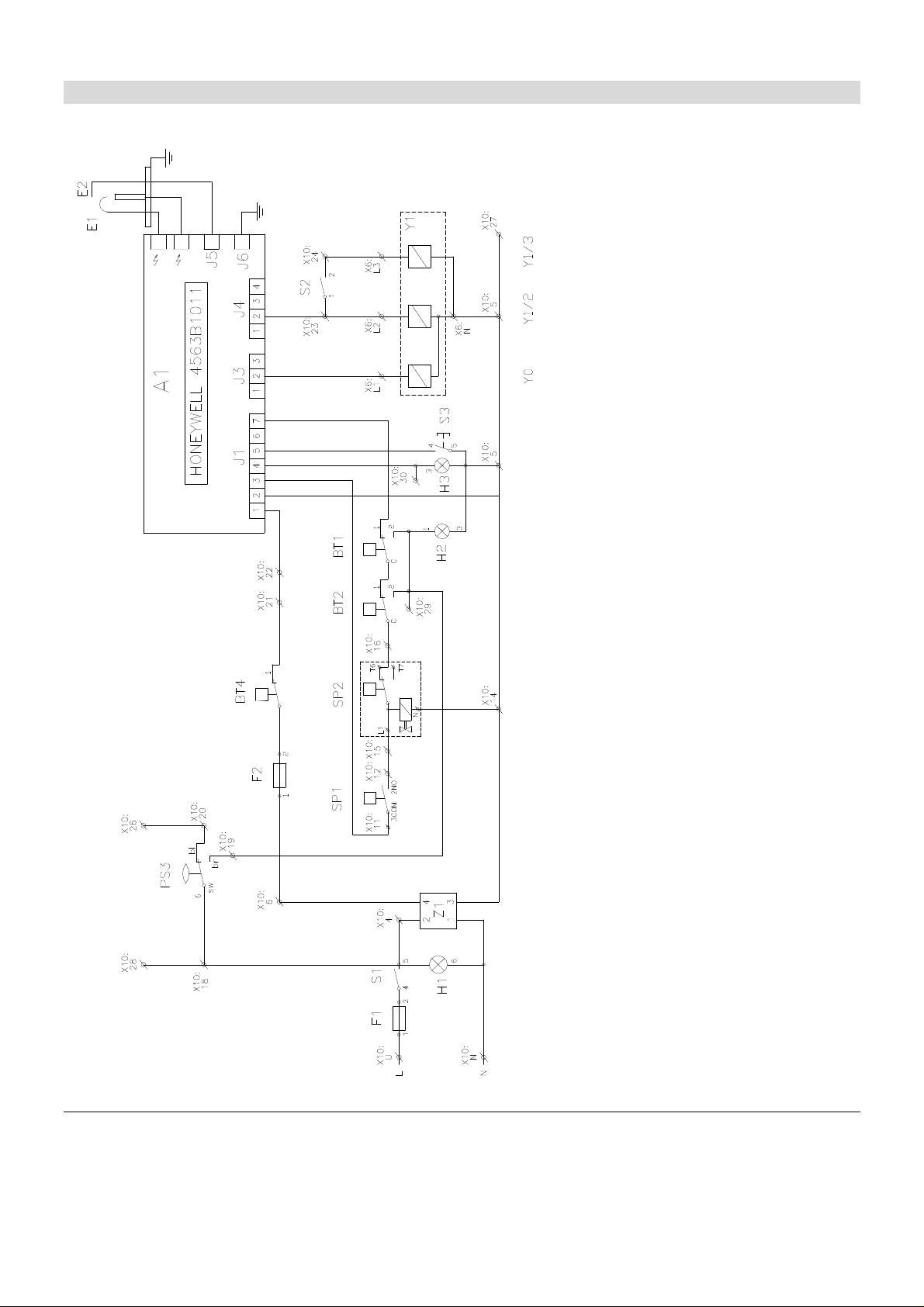
4 Electrical connections flow sheet
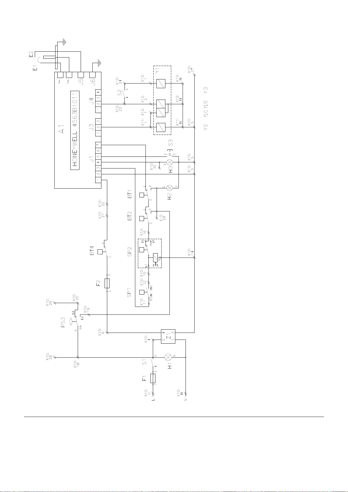
ϑ
ϑ
Y1 Gas Valve Honeywell VR4601QB 2001
Z1 Anti-interference element
BT1 safety thermostat
BT2 combustion products thermostat
BT4 boiler thermostat
PS3 Minimal water level guard
SP1 Minimal gas pressure guard
SP2 Gas flange leaktightness guard
X6 Gas valve connector
ϑ
P
P
Automatics – Honeywell 4563B1011
Elementary wiring diagram of VIADRUS G 90 – 8 sectional boiler for Honeywell version
At VIADRUS G 90 version – 8 sections there isn’t used the tightness watching system at SP2 gas fitting
14
“ionising failure” signalling
Ignition electrode
Signalling "Boiler under voltage"
Ionization electrode
Fuse 4 A
Fuse 2,5 A
Reduced/rated output switch
“failure” signalling
Main power switch
Pushbutton RESET
0 Boiler’s terminal plate
Page 15
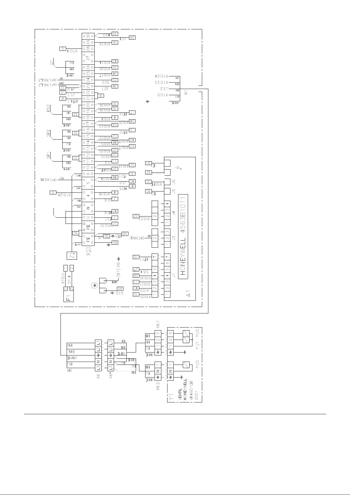
console
Burner
:
Green-yellow
Grey
Red
Brown
Blue
Black
Small burner I. step
Minimal water level guard
Minimal gas pressure guard
Gas flange leaktightness guard
Automatics – Honeywell 4563B1011
0 Boiler’s terminal plate
Gas Valve Honeywell VR4601QB 2001
Fuse 4 A
Anti-interference element
Circulating pump
Gas valve connectors
Wiring diagram of 8 sectional VIADRUS G 90 boiler for Honeywell version
15
Page 16
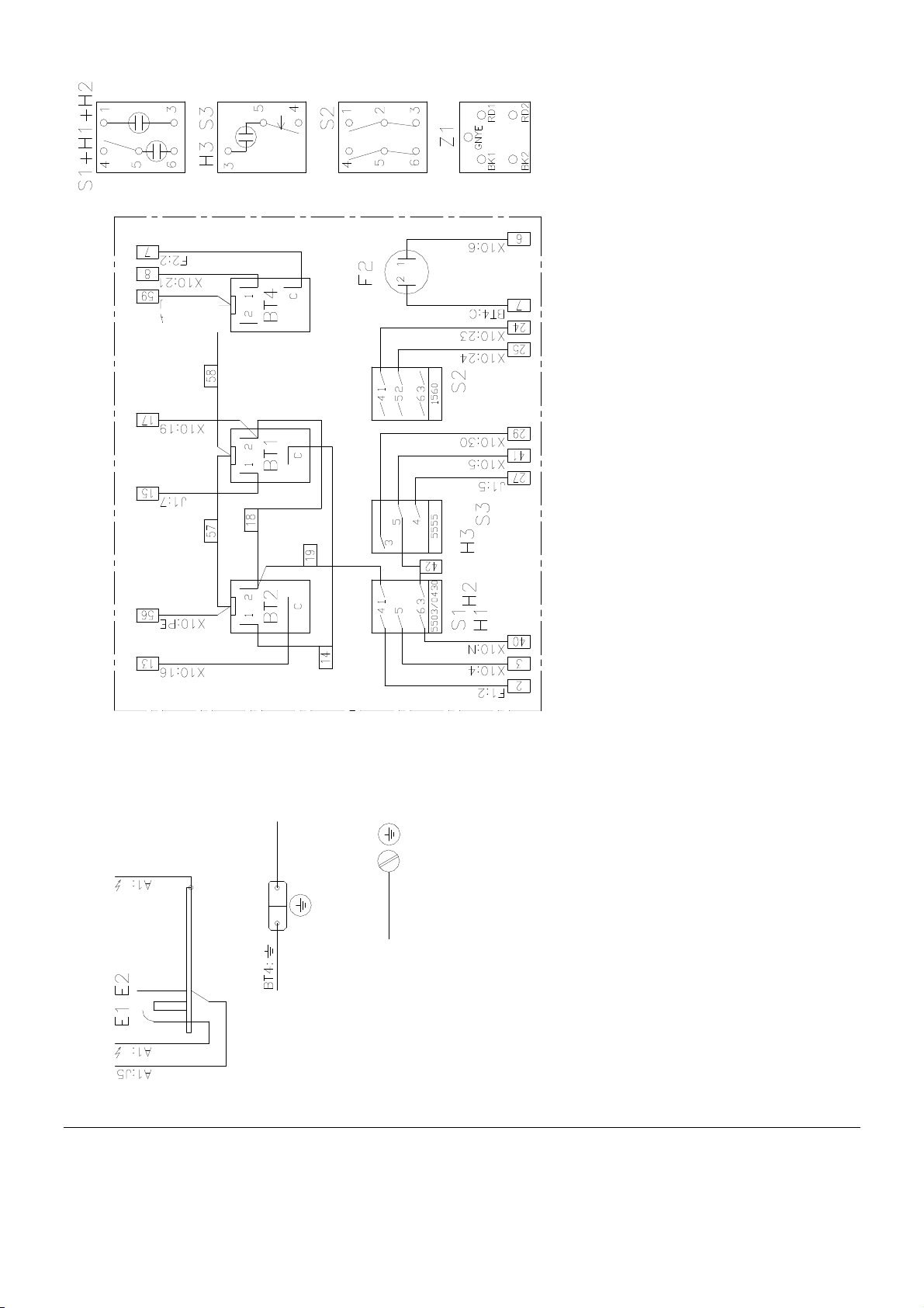
Panel
console
Boiler’s body
Boiler’s body
Panel
console
Wiring diagram of 8 sectional VIADRUS G 90 boiler for Honeywell version
16
Panel
console
safety thermostat
“ionising failure” signalling
Ignition electrode
Signalling "Boiler under voltage"
Small burner ionization electrode
Fuse 2,5 A
3 Burner ionization electrode
Reduced/rated output switch
“failure” signalling
Main power switch
boiler thermostat
Pushbutton RESET
T2 combustion products thermostat
Page 17
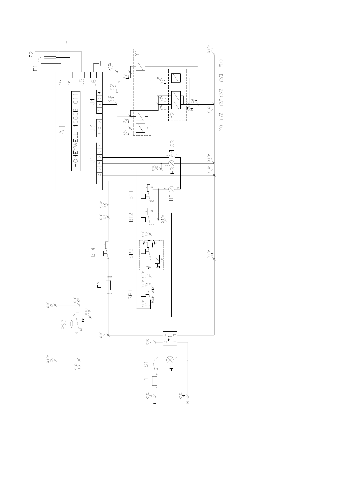
ϑ
ϑ
Y1 Gas Valve Honeywell VR4601QB 2001
Y2 Gas Valve Honeywell VR4605QB 2002
Z1 Anti-interference element
BT1 safety thermostat
BT2 combustion products thermostat
BT4 boiler thermostat
PS3 Minimal water level guard
SP1 Minimal gas pressure guard
SP2 Gas flange leaktightness guard
X6, X7 Gas valve connectors
ϑ
P
P
“ionising failure” signalling
Automatics – Honeywell 4563B1011
Ignition electrode
Signalling "Boiler under voltage"
Ionization electrode
Fuse 4 A
Fuse 2,5 A
Reduced/rated output switch
“failure” signalling
Main power switch
Pushbutton RESET
0 Boiler’s terminal plate
Elementary wiring diagram of VIADRUS G 90 – 10, 12, 15 sectional boiler for Honeywell version
17
Page 18
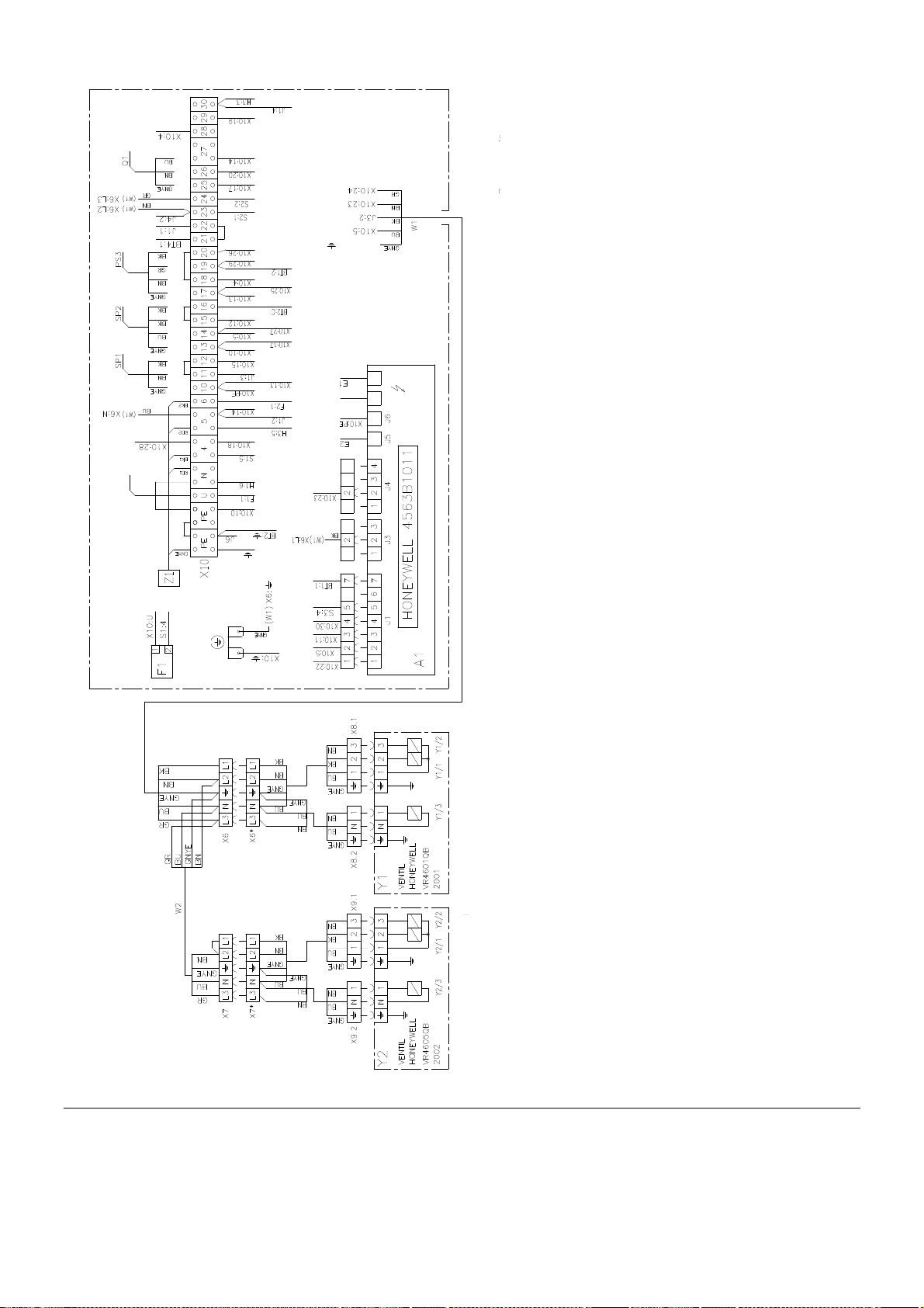
console
:
Green-yellow
Grey
Red
Brown
Blue
Black
Burner
Small burner I.
I. step
Automatics – Honeywell 4563B1011
0 Boiler’s terminal plate
Gas Valve Honeywell VR4601QB 2001
Fuse 4 A
Wiring diagram of 10, 12, 15 sectional VIADRUS G 90 boiler for Honeywell version
18
Minimal water level guard
Minimal gas pressure guard
Gas flange leaktightness guard
Circulating pump
Anti-interference element
2 Gas Valve Honeywell VR4605QB 2002
, X7 Gas valve connectors
Page 19
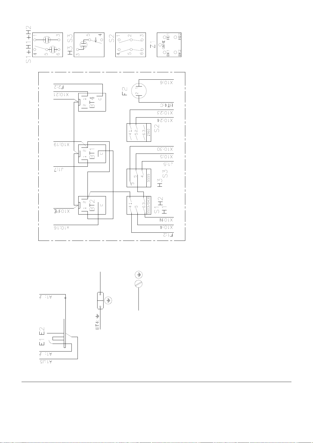
Panel
console
Boiler’s body
Boiler’s body
Wiring diagram of 10, 12, 15 sectional VIADRUS G 90 boiler for Honeywell version
19
Panel
console
Panel
console
“ionising failure” signalling
Signalling "Boiler under voltage"
Ignition electrode
Small burner ionization electrode
“failure” signalling
Fuse 2,5 A
3 Burner ionization electrode
Main power switch
safety thermostat
combustion products thermostat
Reduced/rated output switch
boiler thermostat
Pushbutton RESET
Page 20
ϑ
ϑ
Y1 Gas Valve Dungs MB-ZRDLE 412B01S22
Z1 Anti-interference element
BT1 safety thermostat
BT2 combustion products thermostat
BT4 boiler thermostat
PS3 Minimal water level guard
SP1 Minimal gas pressure guard
SP2 Gas flange leaktightness guard
ϑ
P
P
X11,X12,X13 Gas valve connectors
Automatics – Honeywell 4563B1011
Ignition electrode
Ionization electrode
Elementary wiring diagram of VIADRUS G 90 – 10, 12, 15 sectional boiler for DUNGS version
20
Signalling "Boiler under voltage"
Fuse 4 A
Fuse 2,5 A
Reduced/rated output switch
“failure” signalling
“ionising failure” signalling
Main power switch
Pushbutton RESET
0 Boiler’s terminal plate
Page 21
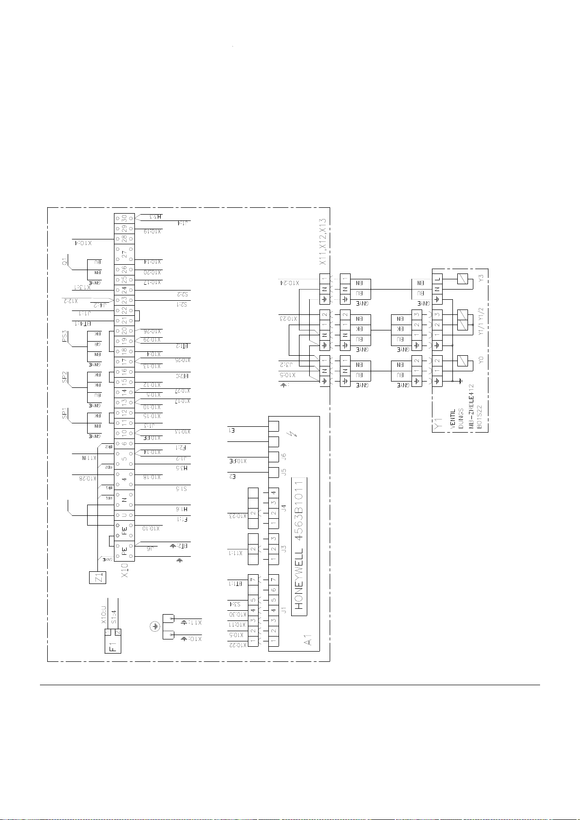
Gas valve connectors
Burner
4563B1011
Automatics – Honeywell
412B01S22
Minimal water level guard
Minimal gas pressure guard
Gas flange leaktightness guard
0 Boiler’s terminal plate
Gas Valve Dungs MB-ZRDLE
Fuse 4 A
Anti-interference element
Circulating pump
I. step II. step
Terminal
plate console
Wiring diagram of 10, 12, 15 sectional VIADRUS G 90 boiler for DUNGS version
Green-yellow
Grey
Red
Brown
Blue
Black
21
Page 22

Panel
console
Boiler’s body
Boiler’s body
Wiring diagram of 10, 12, 15 sectional VIADRUS G 90 boiler for DUNGS version
Additional directives for installation and operation are contained in the “Manual for operation and Installation of Boiler VIADRUS G
Manufacturer reserves the rights to changes made in the context of product innovation; these might not be included in this Manual
Panel
console
Panel
console
safety thermostat
combustion products thermostat
“ionising failure” signalling
Ignition electrode
90”, also included in the shipment.
Signalling "Boiler under voltage"
Small burner ionization electrode
Fuse 2,5 A
3 Burner ionization electrode
hereto presented.
Reduced/rated output switch
“failure” signalling
Main power switch
boiler thermostat
Pushbutton RESET
22
Page 23

Page 24

VIADRUS
VIADRUS a.s.
| CZ - 735 81 | Bohumín
Bezručova 300
E-mail
G 90
www.viadrus.cz
 Loading...