

Page 1
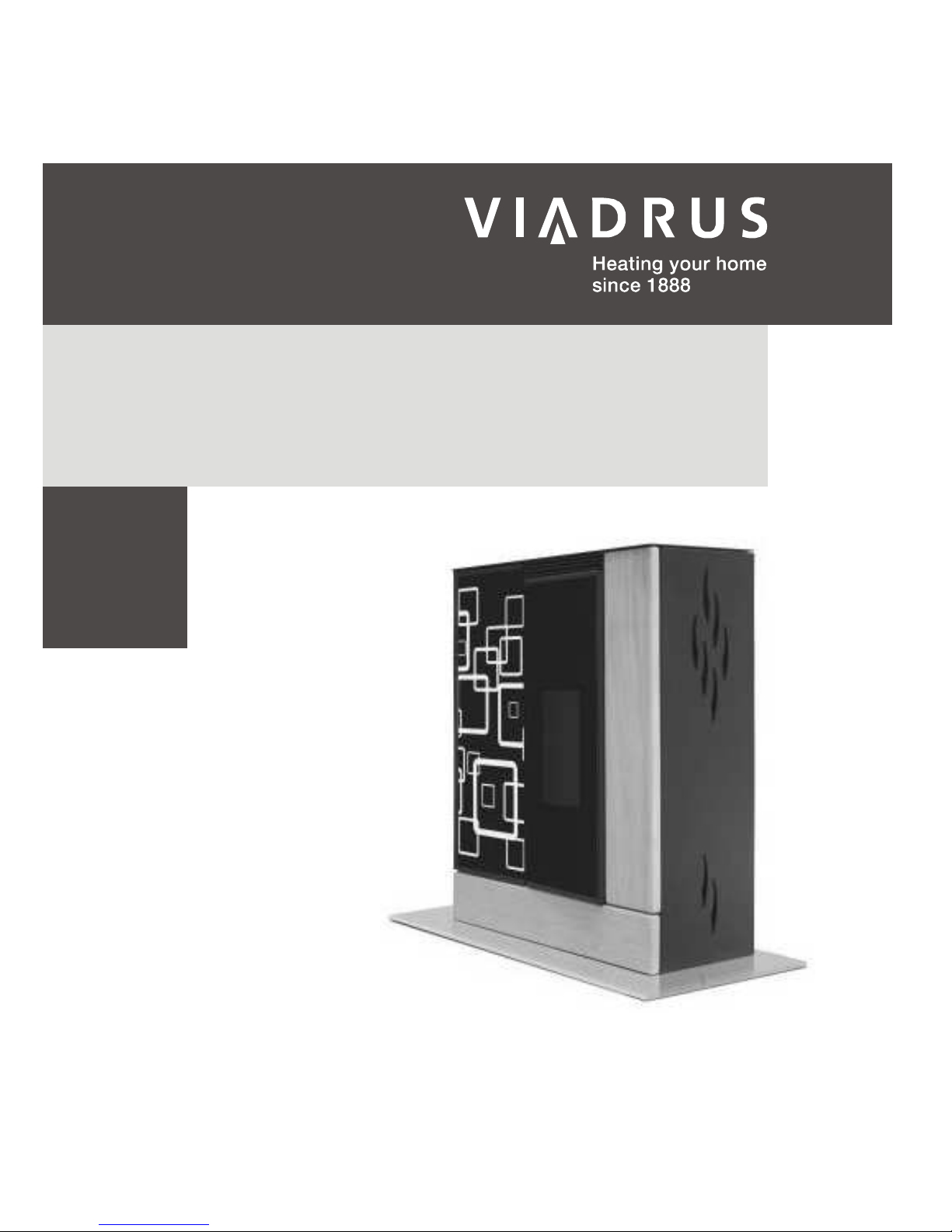
AGURO
Manual for installation, operation
and maintenance
GB_2016_30
GB_2016_31
It was tested according to/complies with norms:
• EN 14 785:2007
• 15a B-VG
• Din +
• BIm SchV 2
Page 2

CONTENT
page
1 Pellet stove usage and advantages ........................................................................................................................ 3
2 Pellet stove technical description ............................................................................................................................ 3
3 Transportation and storage ..................................................................................................................................... 5
3.1 Transportation .................................................................................................................................................. 5
3.2 Storage ............................................................................................................................................................ 5
4 Placement and installation ...................................................................................................................................... 5
4.1 Regulations and directives ............................................................................................................................... 5
4.2 General instructions for placement and installation ......................................................................................... 5
4.3 Rules for placement ......................................................................................................................................... 6
4.4 Connection of the pellet stove to the chimney ................................................................................................. 7
4.5 Connection of central air supply ...................................................................................................................... 7
5 Commissioning ........................................................................................................................................................ 8
5.1 Opening of the pellet stove door ...................................................................................................................... 8
5.2 Safety instructions ........................................................................................................................................... 8
5.3 Fuel .................................................................................................................................................................. 9
5.4 Main principles of operation ............................................................................................................................. 9
5.5 The first commissioning ................................................................................................................................. 10
6 Manipulation with the control electronics .............................................................................................................. 10
6.1 User menu ..................................................................................................................................................... 10
6.2 Remote control .............................................................................................................................................. 15
6.3 Stove first ignition and shutdown procedure.................................................................................................. 16
6.4 Power degree selection mode ....................................................................................................................... 16
6.5 Room thermostat value adjustment mode ..................................................................................................... 16
6.6 Pellet supply and exhaust fan rpm adjustment mode .................................................................................... 17
6.7 Alarms on the display and their removal ....................................................................................................... 17
7 Pellet stove maintenance and cleaning ................................................................................................................ 18
7.1 Clean-up of glass and the stove surfaces ..................................................................................................... 18
7.2 Clean-up of the heating chamber .................................................................................................................. 19
7.3 Clean-up of the pellet reservoir...................................................................................................................... 19
7.4 Clean-up of the flue channel .......................................................................................................................... 19
7.5 Clean-up of the smoke-flues and the smoke-flue pipes ................................................................................ 20
7.6 Clean-up of the cladding of the exhaust fan (it is not necessary, or only in extraordinary cases) ................ 20
8 Possible causes of operation problems and their removal ................................................................................... 21
9 Liquidation of transporting packing, liquidation of the product after the lapse of service life ................................ 22
10 Warranty conditions............................................................................................................................................... 22
Page 3

3
Dear customer,
We thank you that you have bought a AGURO pellet stove, thus having shown your confidence in VIADRUS brand.
Your new stove was manufactured in a company that is a holder of ISO 9001:2000 certification.
Before installation and commissioning, please carefully acquaintance with the instruction manual for your new
pellet stove. It will help you to avoid possible problems incurred as a result of violation of guidance and instructions
specified in this manual, which can – under certain circumstances – lead to a damage of the stove. Save this
manual for searching other information in the future.
1 Pellet stove usage and advantages
The automatic AGURO pellet stove is also determined for permanent heating of dwelling and commercial premises.
Fuel is conveyed by means of an auger from the fuel reservoir into the burner bowl, whereas the fuel quantity is
automatically corrected in dependence on a required heating power. In case of the full fuel reservoir, depending on
the required temperature in the room, the stove can be operated during about 30 hours.
The stove is controlled with help of a control unit, which is integrated in the fuel reservoir cover. A user can choose
one of the working modes: “Heating” or "Auto" with the week programming.
The control unit regulates the kindling phase, the heating phase and cooling phase, and ensures by this safety
operation of the pellet stove. The display displays a working mode, in which the stove is occurred at the moment.
Eventual error messages are displayed on the display in a text form with specification of date and time.
2 Pellet stove technical description
It is a stove assembled from high quality steel plates. The stove furnace is equipped with a cast-iron burner bowl.
The pellet stove doors are equipped with a heat-resistant glass, and their structure allows opening in the horizontal
direction to the left. A part of the pellet stove is a removable ash-pan. The pellet stove surface is protected by heatresistant painting with the resistance up to 650°C (heating chamber) and 350°C (other steel-plate parts – a side
wall, a rear cover, a stove cover, etc.).
Tab. №. 1 Main thermo-technical parameters of the pellet stove
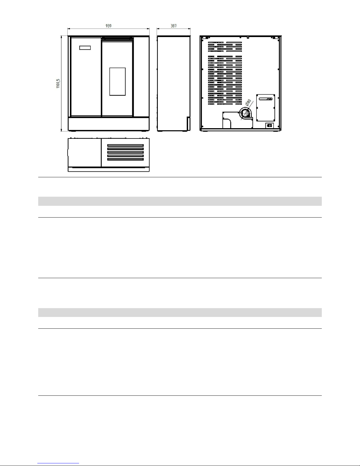
Total high mm 1101
Width mm 931
Depth mm 396,
Dead weight kg 209
Neck - chimney mm 80
Neck – air supply mm 50
Fuel reservoir volume kg 35 kg
Min. chimney operation draught Pa 10-15
Dwelling premise heat ability
(in dependence on a degree of facility insulation)
m3 50 - 220
Effectiveness % 87,3
Nominal heating power kW 6,4
Heating power range kW 2,6 – 6,5
Electric power supply V/Hz 230/50
Fuel consumption of electric energy W appr. 25
Electric fuse A 2,5
Fuel consumption at min ~ max heating power
kg/h
0,7 ~ 1,6
Average combustion products temperature behind the neck °C 143
Combustion products’ mass flow rate g/s 6,5
Content of CO at 13% O2 % 0,018
Connection to the electric power supply network:
The stove is supplied from the electric power supply network with help of a cable with the length of about 1,5 m
with an Euro terminal, which is a part of the package of the stove. The cable is to be connected to the electric
socket of 230 V/50 Hz. The average consumption of electric energy during operation is about 25 W, and the
average consumption of electric energy during the kindling process is 135 W. The supply cable has to be laid so
that it is not in contact with sharp edges or corners and is not in contact with hot surfaces of the stove.
Page 4

4
Legend:
1. Protective grate
2. Reservoir
3. Auger
4. Auger motor
5. Control unit
6. Manostat
7. Flue exhauster
8. Cast-iron door frame
9. Display
10. Cast-iron door
11. Reservoir cover
12. Ash-pan
13. Door
14. Stone
15. Stone
16. Steel heat-exchanger
17. Insulation
18. Ceramic insulation
19. Rear cladding
20. Cast-iron burner bowl
21. Heating chamber
22. Cast-iron heat-exchanger
23. Cleaning cover
24. Tangential electric fan
25. Cleaning cover
26. Height-adjustable legs
27. Side cladding
Fig. №. 1 Main parts
Page 5
5
Fig. №. 2 Main dimensions
3 Transportation and storage
3.1 Transportation
The pellet stove has to be only transported in the vertical position, in the original package and with properly fixation
against movement and falling. Transportation has to be performed in close space in order to avoid damage from
atmospheric conditions. During handling it is necessary to follow the vertical position; the stove mustn’t be declined
in any way to avoid its damaging. The stove has to be griped and convey by the bottom metal parts.
After taking-over the product, please properly check integrity and completeness of the package, including
its content.
3.2 Storage
The pellet stove has to be stored in a dry and tempered environment. It is necessary to store and handl it in the
vertical position. Please be extra careful during handling.
4 Placement and installation
4.1 Regulations and directives
EN 14 785:2007 Pellet stoves.
ČSN 73 4230 Hearths with open and closed fire grates.
ČSN EN 1443 Chimneys – General requirements.
ČSN 73 4201 Hearths and smoke-flues – Design, implementation and connection of fuel consumers.
ČSN EN 13501-1+A1 Fire protection classification of building products and building structures.
ČSN 06 1008 Fire safety of heating equipment.
.
4.2 General instructions for placement and installation
Each pellet stove has to be implicitly placed and installed so that there were observed the conditions specified by
local regulations or national and European norms as amended, including their additions, as well as in accordance
with instructions specified in this instruction manual.
The pellet stoves are determined for installation in dry premises that are characterized by a valid norm as
unaggressive environment without any explosive are combustible gases.
Page 6
6
Before installation of pellet stoves it is necessary to carry out revision of the breast, into which the stove has to be
connected, including design and assessment of the flue channel, which has to provide safety exhaust of flue gases
from the connected stove. Only one consumer can be connected to the flue channel.
At installation it is necessary to provide sufficient access for cleaning of the consumer, the flue gas ducting and the
chimney.
In interior where a pellet stove is placed, it is not recommended to place equipment for air exhausting (for example,
a fume hood), which could invoke backward draught and leakage of flue gases into a room. If anyhow this
equipment is placed in the interior, it is necessary to provide regulation of its draught and suction of combustion air
from an extern room (a cellar, a technical room, etc.). Only overpressure air conditioning can be used.
4.3 Rules for placement
The consumer has to be put up on a firm basement with a corresponding capacity, preferably on a concrete or
other inflammable plate. If the existing set doesn’t comply with this necessary condition, it is necessary to make
sufficient measures to satisfy this requirement.
In case of installation to the floor from a combustible material, it is necessary to place the consumer on an
insulating pad from an inflammable material, which overlapped the ground plan of the consumer by 800 mm in the
direction of radiation, 400 mm from remaining sides.
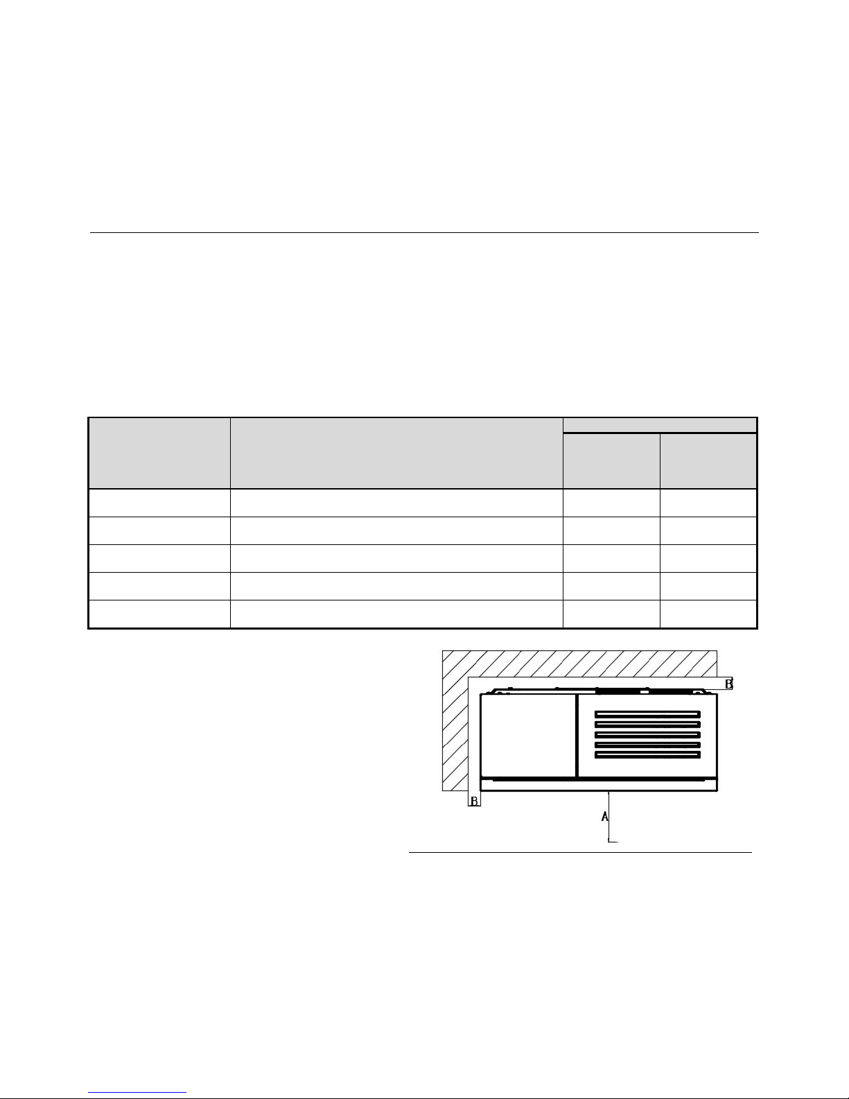
It is not allowed to put subjects from combustible materials on the consumer and on the distance less than the
safety distance (see the following table). In case of unknown stage of combustibility it is necessary to go from the
distance for the stage E (F).
Tab. č. 1 Grade of reaction to fire
Grade of reaction to fire
Examples of building materials and products included in
the reaction of fire (extract from ČSN EN 13501-1+A1)
Minimum distance (mm)
Direction
perpendicular
to the radiating
wall
Other
directions
A1 – incombustible
Granite, sandstone, concrete, bricks, ceramic tiles, mortars,
fireproof plasters,...
- -
A2 – hardly combustible
acumin, izumin, heraklit, lignos, boards and basalt felt,
fibreglass boards,...
800 400
B – heavily combustible
Beech and oak wood, hobrex boards, plywood, werzalit,
umakart, sirkolit,...
800 400
C (D)
– moderately
combustible
Pinewood, larch, whitewood, chipboard and cork boards,
rubber flooring,...
800 400
E (F) – lightly combustible
Asphaltboard, fibreboards, cellulose materials, polyurethane,
polystyrene, polyethylene, PVC,...
1600 800
As the minimal distance from combustible or noncombustible materials, you can follow the following
values:
Combustible materials:
A > 800 mm
B > 100 mm
Non-combustible materials:
A > 400 mm
B > 50 mm
Fig. №. 3
Page 7
7
4.4 Connection of the pellet stove to the chimney
Before commissioning the pellet stove, check and testing of the flue channel has to be
performed even before closing the flue channel by the sheathing of the heat-air chamber.
These activities may be only performed by a qualified person, for example, a chimney-sweeper
company. The result of checking has to be recorded into the revision report of the flue
channel.
With regard to low demand factor of installation of the pellet stove, a customer may install the
stove by himself/herself. However we recommend ordering this installation from a proper
trained specialized building company or a chimney-sweeper or a stove-fitter company.
Revision of the flue channels has to be car
ried out:
•
before commissioning the flue channel
•
after each building modification of the chimney
•
before a change or new installation of the consumer.
Revision has to be performed by a qualified person in the sphere of chimneys – by
engineering inspector of chimneys.
• Flue exhausting is ensured by means of a flue exhauster, which is a part of the pellet stove.
• The stove has to be connected to a separate chimney. It is not allowed to draw off flue gasses from other
equipment to this chimney.
• The chimney can be in classical design (a brickwork), or from stainless steel or from ceramics.
• Usual pipes or springy steel pipes for flue gas ducting can be used for connection to the chimney.
• All parts of the flue gas ducting up to the entrance to the chimney have to be gas-tight from the reason of
possible occurrence of overpressure in the output of flue gases.
• The pipe of the flue gas ducting mustn’t intervene to a free cross-section of the chimney.
• The stove complies with requirements for connection to chimneys designed for temperature of flue gases of
350 °C.
• The minimum required chimney draught is 10 Pa. Draught is influenced both by the length of the chimney, and
by the surface of the chimney, and by quality of its sealing. The minimum recommended length of the chimney
is 3,5 m from the place of falling-in the flue gas ducting to the chimney and a suitable minimum cross-section
is 150 x 150 cm.
• The outer diameter of the connecting mouthpiece for smoke gas is 80 x 1,5 mm.
• The flue gas ducting has to be made from tightened steel or stainless pipes. Two 90° elbow-pieces can be
used.
• In case of placement of the flue gas ducting on the outer side of the building, it has to be equipped with
thermal insulation.
• Flue gas ducts with sharp bends and a horizontal routing decrease chimney draught. The maximum horizontal
piece of the flue gas ducting is 2 m, under condition that the length of the flue gas ducting is at least 5 m.
• The flue gas ducting has to be accessible for checking and cleaning. It is necessary to provide possibility of
sweeping of the entire length of the chimney, and the chimney door has to be easily accessible.
• Check attentively whether the chimney is tight and that no leakage of flue gases occurs around the chimney
door and connection of the flue gas ducts.
• Flue gases are to be drawn through the flue gas ducting with the diameter of 150 mm connected to the neck of
the flue gas ducting of the stove, which is placed on the upper (rear) part of the stove.
4.5 Connection of central air supply
Connection of central air supply has to be realized in air-tight buildings, where the content
of oxygen in the room heated by the pellet stove can be decreased.
• Connect the hose to the suction neck for air on the rear wall (Ø 50 mm).
• The entrance of the air supply line has to be placed in outdoor space or in sufficiently vented room of the
building.
• At installation of the stove in a building with controlled ventilation of habitable premises, the entrance of air
supply mustn’t be placed in a room, which is connected to the associated ventilation system.
• In order to ensure sufficient air supply, the supply line mustn’t by longer than 3 m and mustn’t have too much
bends. The minimum diameter of the supply line is 50 mm.
• If the supply line enters into the outdoor space, it has to be bent by 90° in the down direction or has to be
ended in the dead air region.
Page 8
8
5 Commissioning
Wrong operation and insufficient combustion of fuel brings to a damage of
the product.
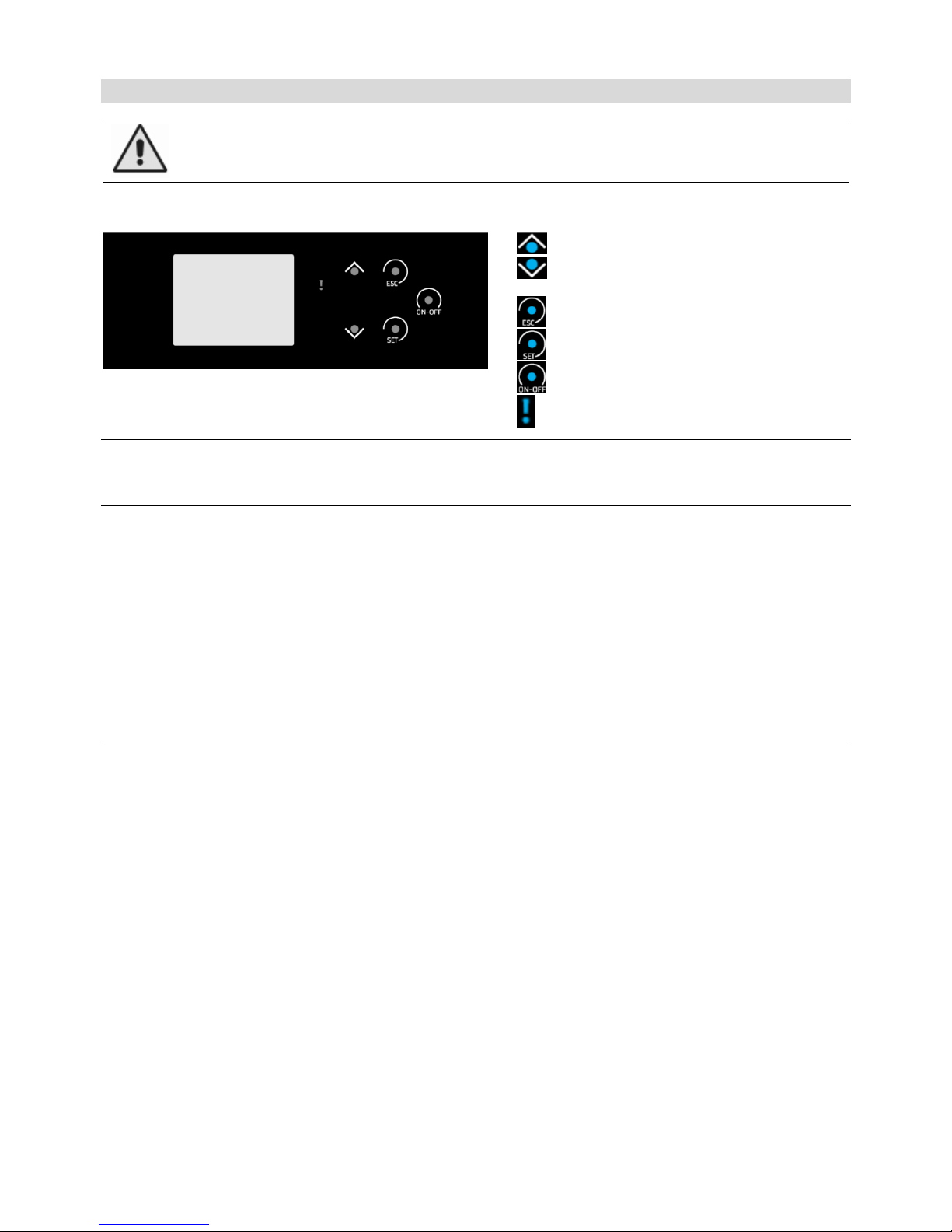
The control of the AGURO pellet stove is very easy. Control elements of the pellet stove are displayed in Fig. 4
Navigation in menu „UP“, increase the value
Navigation in menu „DOWN“, decrease the
value
Button in menu „EXIT“
Button in menu „CONFIRM“
Button in menu „ON/OFF“
Button „WARNING“
Fig. №. 4
5.1 Opening of the pellet stove door
The stove has two doors. The cast-iron door separates the heating chamber from other environment, and the
glassed one is decorative and completes the pellet stove design.
Be particular about sealing surfaces of the inner frame of the cast-iron door to ensure their easiest closing. The
cast-iron door can be opened with help of a handle; the decorative door can be opened by means of a clip and a
magnet (they are a part of delivery). Observe cleanness of the both doors.
The both doors always during stove operation have to be closed, otherwise the stove wouldn’t work
correctly and can be damaged!
If necessary, always open the cast-iron door slowly and carefully, in order to avoid sudden change of pressure in
the heating chamber and escape of smoke into the room.
5.2 Safety instructions
• At handling and unpacking, be careful and observe safety instructions!
• In case that there is a danger of occurrence of flammable gases for the temporary period in the room
with an installed stove (for example, during gluing of linoleum, at painting work, etc.), the pellet stove
has to be put out of operation even before occurrence of this danger!
• During burning of the surface painting of the stove at the first firing-up, it is necessary to ventilate all
the time and bring sufficient quantity of fresh air into the room!
• At operation it is necessary to provide sufficient supply of combustion air and safety withdrawal of
flue gases!
• The both doors have to be always closed!
• The pellet stove may only be operated by a capable adult person!
• Ensure that children, persons with mental disabilities and domestic animals cannot get to the space of
the furnace itself or very hot parts during operation of the stove (doors, glass, side covers, the furnace
cover, etc.) – danger of burning and possible life danger!
• For the entire period of operation, fire in the stove has to be regularly checked!
• In case of simultaneous operation of other heating device in the same room, it is necessary to ensure
sufficient ventilation!
• Don’t touch the outer surfaces of the stove – danger of burning and possible life danger, except of
control and regulating elements!
• Never extinguish fire in the pellet stove by water!
• Ash from the ash-pan has to be removed carefully and with using of protective equipment, and only
when the pellet stove is out of operation!
Page 9

9
• Put ash into inflammable vessels with a cover!
• The consumer mustn’t be used for combustion of waste, rubbish; and no liquid fuels can be used in
any combination! Use only recommended fuels.
• In case of occurrence of a fire of deposits in the chimney, extinguish quickly the fire in the stove by a
dry-power extinguisher or by sand, remove all flammable material situated near the stove and the
chimney body. Close the door, control elements of the stove and the smoke regulating shutter (if it is
installed) and immediately announce the fire to a fire-fighting service!
• Ensure performance of inspection of the pellet stove and flue-gas channel, including the chimney by a
qualified person before repeated commissioning!
• It is not allowed to perform any modification of the product, except of mounting and service works
performed by qualified persons.
• It is possible to use only spare parts approved by the manufacturer for repairs.
In case of non-observance of these conditions, a user loses a right to guarantee repairs.
5.3 Fuel
The guarantee of clean and good combustion is the using of only dry and naturally stocked wood. Fuel is
to be stocked in a dry place.
The stove is determined for firing of high-quality wooden pellets; combustion of, for example, wood chips,
straw or corn is not allowed. Don’t use pellets manufactured from different materials than pressed wooden
matter (for example, from olives, corn, flax, etc.)
Pellets have to comply with at least one of the following directives or norms:
Directive No. 14-2000 of the Ministry of Environment of Czech Republic
DIN 517 31
ÖNORM M 7135
Prescribed granularity of pellets 6 to 8 mm
Water content in fuel max. 12 %
Ash content max. 1,5 %
ATTENTION! Bad fuel quality can significantly negatively influence the power and emission parameters
of the stove.
Quality wooden pellets usually have a smooth sheeny surface, the uniform length and the low share of dust. Lowquality pellets have longitudinal and transverse cracks, the non-uniform length and the high share of dust. Pellets
quality can be also checked by an easy test. Insert some pellets into a glass with water. If the pellets quality is
good, then they will sag down to the bottom, and if their quality is worse, then they will swim on the water surface.
However, the precisely fuel quality can be only determined with help of proper analyzing devices.
During filling-up pellets into the fuel reservoir, be care about not to contact bags with pellets with the hot
surface of the stove.
5.4 Main principles of operation
1. The stove and its operation is controlled automatically, by means of an electronic system. The stove cannot be
overloaded (from the point of view of power), if it is operated in accordance with the instructions manual. Don’t
operate the stove with non-prescribed fuel (ref. chapter 5.3). Combustion of other than prescribed fuel and
non-observance of the above mentioned conditions can bring to a damage of components inside the stove or
the entire stove and to canceling of validity of the warranty.
2. Remove ash from the heating chamber and ash-pan before each kindling.
3. In case of season using and at insufficient draught and atmospheric conditions it is necessary to be very
careful during commissioning.
4. After long-term interruption of operation, it is necessary to carry out a check that the flue gas channel is not
impacted.
5. We recommend before each season to perform maintenance, including cleaning according to chapter No. 7.
6. The stove is equipped with a system for automatic cleaning of the burner bowl during operation. This cleaning
is set in the system to one time per hour for the period of 30 sec. The flue exhauster will be switched on to the
maximum rotation speed, by which the burner bowl will be blown-over in order to prevent obstruction of holes
for supply of combustion air on the bottom surface of the bowl. That’s why don’t be surprised, when this
activity automatically occurs during operation.
Page 10
10
5.5 The first commissioning
At the first kindling, because of burning-in of the surface painting of the pellet stove, it is
necessary to ventilate constantly and supply enough quantity of fresh air to the room!
• Before the first commissioning, it is necessary to remove labels and withdraw parts of accessories from the
ash-pan or from the combustion chamber; this rule is also valid for a possible transport stopper.
• Check a right placement of the burner.
• Close the door of the combustion chamber.
• Fill up the bunker by normative wooden pellets (Ø 6 mm).
• Connect the power supply cable.
• Switch over the main switch to the position "1".
• In case that your house has mechanical ventilation and there is low pressure inside, open the window near the
stove for some minutes till flame burn up.
6 Manipulation with the control electronics
You may perform the following functions in the user menu:
•
set calibration of the pellet auger,
•
monitor temperature,
•
choose one of four predefined powers,
•
set the timer for the pellet stove switching-on and switching-off.
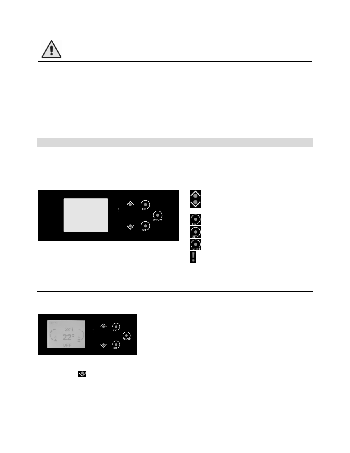
Navigation in menu „UP“, increase the value
Navigation in menu „DOWN“, decrease the
value
Button in menu „EXIT“
Button in menu „CONFIRM“
Button in menu „ON/OFF“
Indication lamp „WARNING“
Fig. №. 5
6.1 User menu
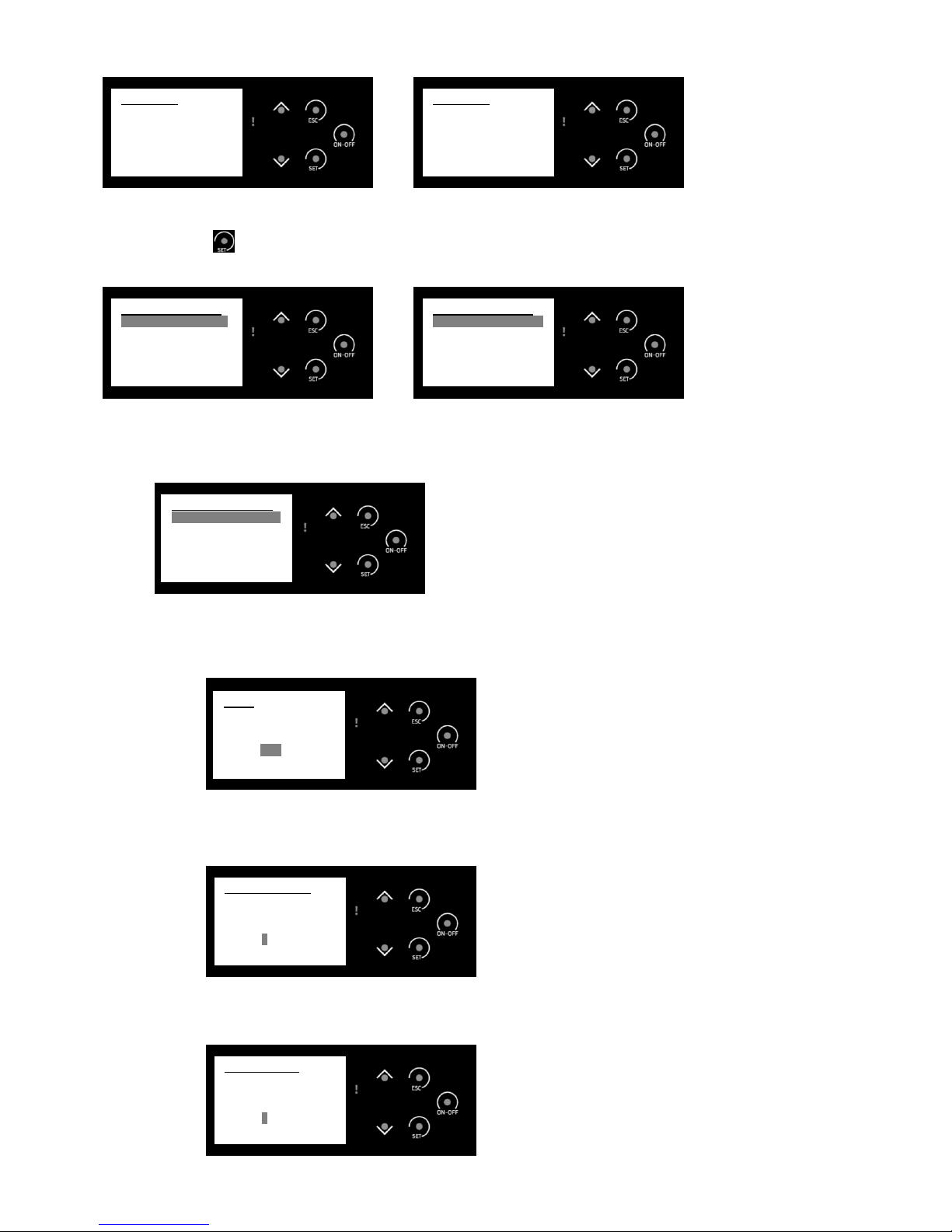
TO ACTIVATE THE „SLEEPING“ DISPLAY, TOUCH THE SCREEN WITH THE CONTROL BUTTONS
BASIC DISPLAY SCREEN
MENU 1 – INFORMATION
Press the button to display basic information of operation of the pellet stove:
• actual flue gases temperature in °C
• adjusted temperature on the room thermostat in °C
• induced air flow-rate (provided the stove is equipped with a sensor for this measurement)
• exhaust fan rotation speed
• number of the stove working hours
• number of the kindling cycles
• product code
Page 11
11
Screen 1 Screen 2
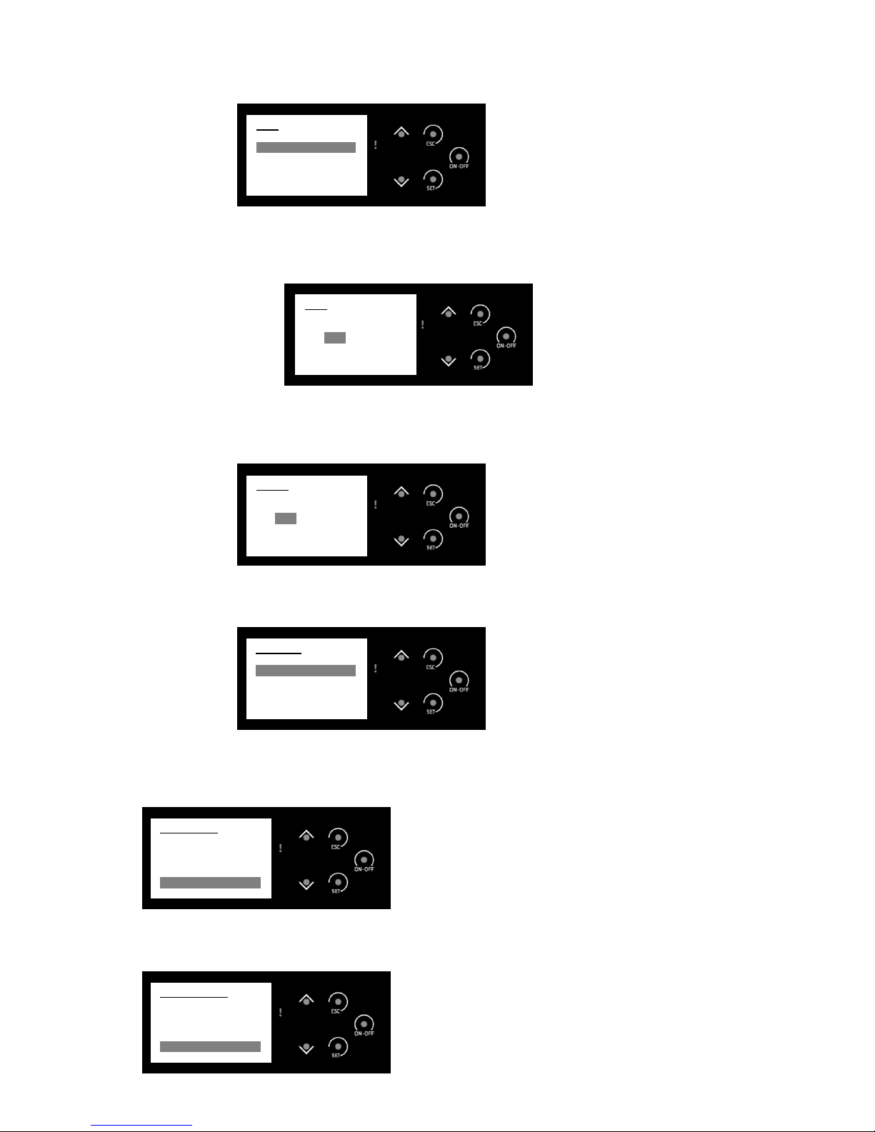
MENU 2 – MENU CUSTOMIZATION -
Press the button – to display the screen for changing of user parameters.
Screen 1 Screen 2
MENU 2.1 – COMBUSTION MANAGEMENT
Manual setting of the power, the rotation speed of the pellet auger and the rotation speed of the exhaust
fan.
MENU 2.1.1 – POWER
Manual setting of the stove power (you can choose an option 1 – 4, or AUTO, which means the
modulating power, i.e. the power that is controlled by the system itself)
MENU 2.1.2 – AUGER CALIBRATION
Manual setting of the feeding speed of the pellet auger (by default, the value „0“ is set)
MENU 2.1.3 – FAN CALIBRATION
Manual setting of the rotation speed of the exhaust fan (by default, the value „0“ is set)
Fan Calibration
Max: +7
Set: 0
Min: -7
Auger Calibration
Max: +7
Set: 0
Min: -7
Power
Pot: Auto
Combustion Manage
Power <<
Auger Calibration
Fan Calibration
Menu Customization
Cleaning Reset <<
Menu Customization
Combustion Manag <<
Heating Management
Remote Control
Chrono
Manual Load
Information
Exhaust T [°C] 23
Room T [°C] 22
Air Flux 0
Fan Speed [rpm] 0
Work Time [h] 138
Information
Ignition [nr] 23
Prod. Code 494-6000
Page 12
12
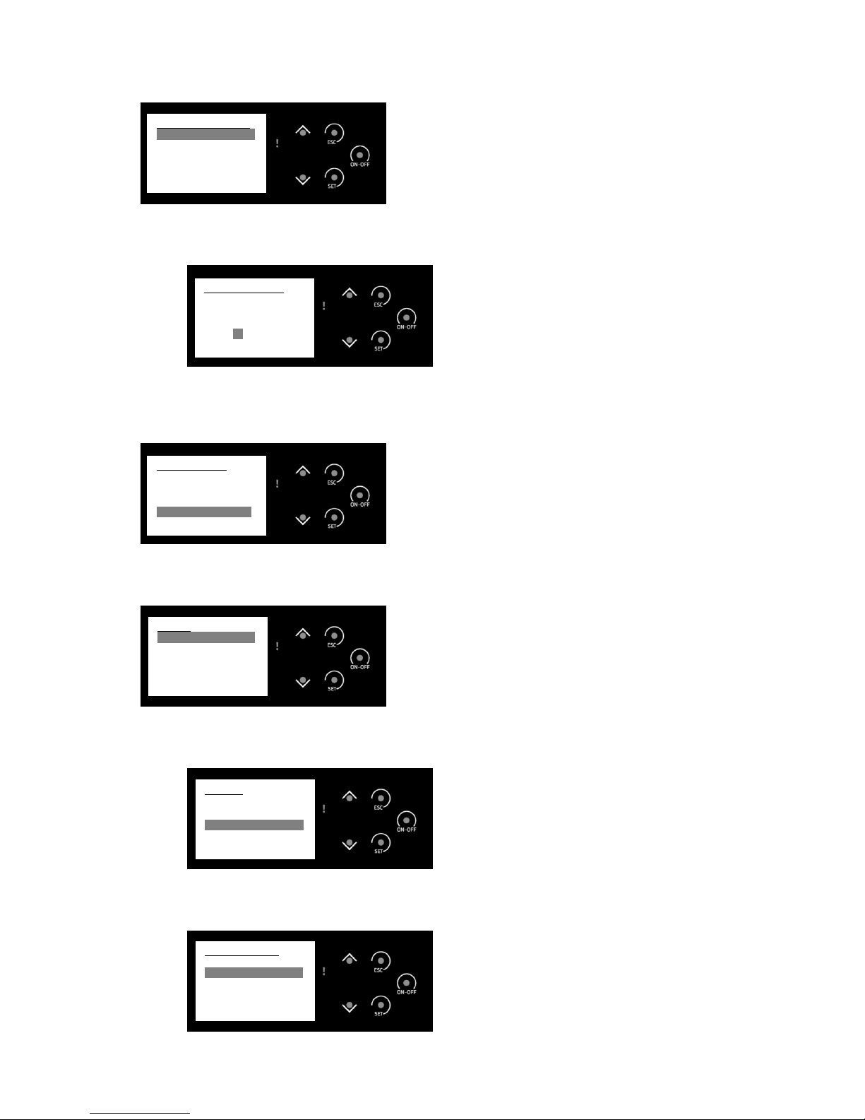
MENU 2.2 – HEATING MANAGEMENT
Manual setting of the room thermostat temperature
MENU 2.2.1 – ROOM THERMOSTAT
Setting of the temperature value on the room thermostat
MENU 2.3 – REMOTE CONTROL
Selection of using of the stove remote control. If the OFF option is chosen, then display touch control is
active.
MENU 2.4 – CHRONO
Setting of the timer for the stove control – selection of a mode, setting of the mode.
MENU 2.4.1 – MODALITY
Selection of the timer mode – daily, weekly, week-end.
MENU 2.4.2 – CHRONO PROGRAM
Manual setting of the timer in the daily, weekly or weekend mode.
Chrono Program
Daily
Weekly <<
Week-End
Modality
Disabled
Daily <<
Weekly
Week-End
Chrono
Modality <<
Chrono Program
Remote Control
ON <<
OFF
Room Thermostat
Max: 40
Set: 28
Min: 10
Heating Management
Room Thermostat <<
Page 13
13
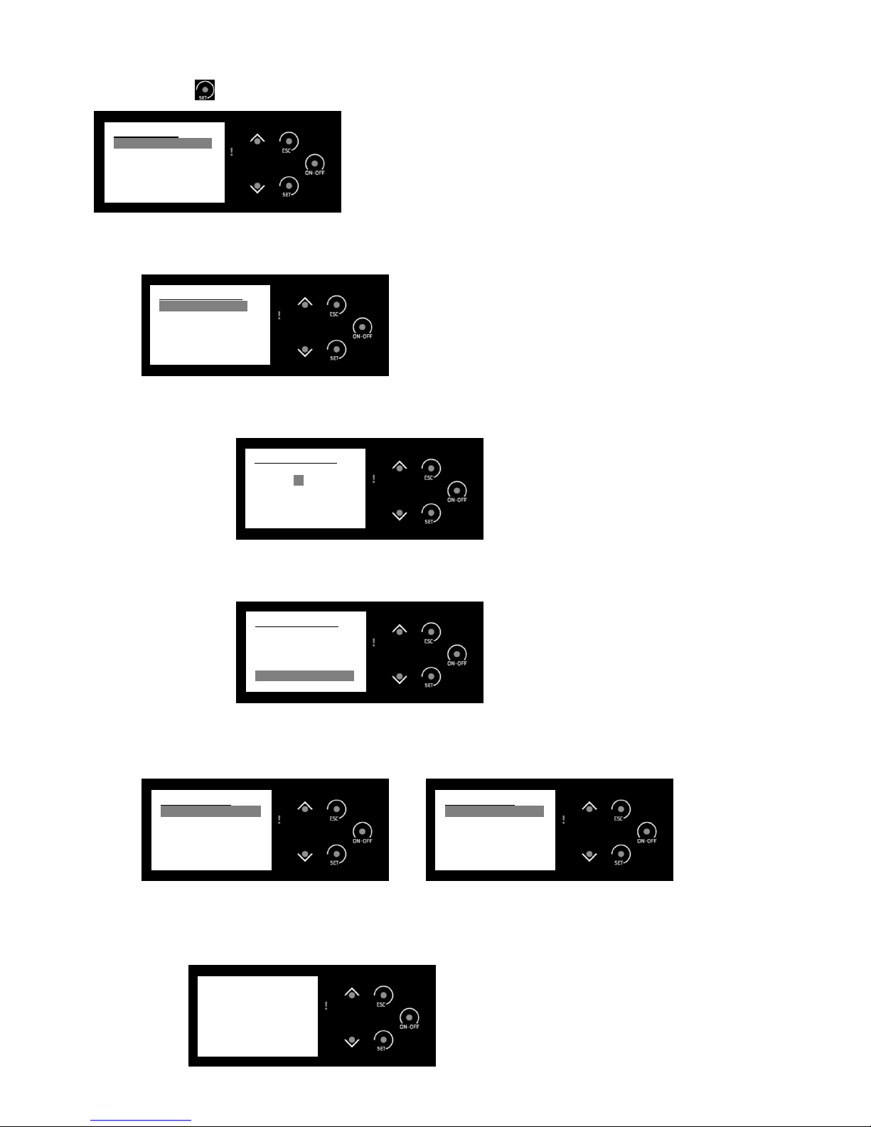
MENU 2.4.2.1 – DAILY
Selection of days in the daily mode – from Mon to Sun (separately for each day)
MENU 2.4.2.1.1
Setting of times of the stove operation from – to for separate days of the mode (3
modes/day)
MENU 2.4.2.2 – WEEKLY -
Setting of the weekly mode from Mon to Sun (the same 3 modes for every day from Mon to
Sun)
MENU 2.4.2.3 – WEEK-END
Setting of separate modes Mon – Fri and Sat - Sun
MENU 2.5 – MANUAL LOAD
A function for manual loading the auger by pellets. It is used to accelerate ignition during the first kindling or
for refilling pellets in case of full discharge of the reservoir.
MENU 2.6 – CLEANING RESET
It serves for erasing date of the previous operation (number of kindling, working hours, etc.)
Cleaning Reset
ON
OFF <<
Manual Load
ON
OFF <<
Week-End
Mon - Fri
Sat - Sun <<
Weekly
Mon – Sun
ON OFF
o 00:00 - 00:00
o 00:00 - 00:00
o 00:00 - 00:00
Daily
Monday
ON OFF
o 00:00 - 00:00
o 00:00 - 00:00
o 00:00 - 00:00
Daily
Monday
Tuesday <<
Wendesday
Thursday
Friday
Page 14
14
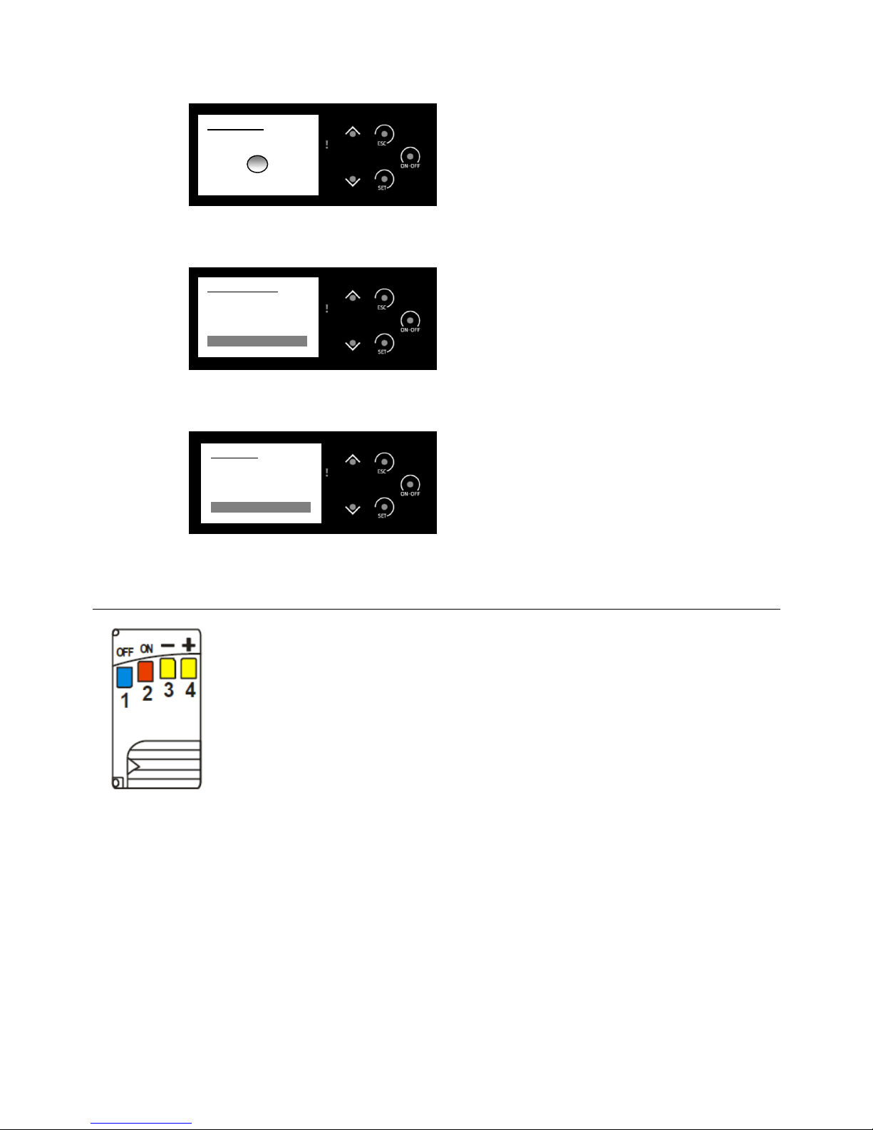
MENU 3 - MENU SETTINGS
Press the button
for at least 3 sec. to set user parameters
MENU 3.1 – KEYBOARD SETTINGS
Date, time and language settings.
MENU 3.1.1 – TIME AND DATE –
Time and date setting
MENU 3.1.2 – LANGUAGE
Language setting
MENU 3.2 – KEYBOARD MENU
Setting of the display contrast, the level of text lighting and button sound at pressing.
Screen 1 Screen 2
MENU 3.2.1 – LEARN MENU – it is not accessible for a user and is protected by a password
MENU 3.2.2 – KEYBOARD ADDRESS – serves only for information for service and is protected by
a password
MENU 3.2.3 – NODE LIST – informative, only for service needs
PASSWORD?
----
Keyboard Menu
Learn Menu <<
Keyboard Address
Node List
Set Contrast
Set Min Light
Keyboard Menu
Mute Keys <<
Keyboard Settings
Espanol
Francaise
Deutsch
English
Italiano <<
Keyboard Settings
06:41
Friday
03/06/2016
Keyboard Settings
Time and Date <<
Language
Menu Settings
Keyboard Settings <<
Keyboard Menu
System Menu
Page 15
15
MENU 3.2.4 – SET CONTRAST
Setting of text contrast on the display
MENU 3.2.5 – SET MIN LIGHT –
Setting of the minimum time of lighting of the display at non-active mode of the display.
MENU 3.2.6 – MUTE KEYS
Switching-off/switching-on of the keys sound at pressing.
MENU 3.3 – SYSTEM MENU – serves for service and is protected by a password
6.2 Remote control
Control elements:
1 activate extinction
2 activate kindling
3 decrease power
4 increase power
Joint configuration of the remote control panel with the pellet stove
• On the remote control panel:
−
Open the battery cover by displacement it to the right
−
Change configuration of the inner switch and put the cover back
• On the switch (situated on the rear side of the stove)
−
Switch-off power supply
−
Switch-on power supply, and at the same time hold one button on the remote
control panel, wait about 5 seconds until an acoustic signal confirms that the
equipment is jointly configured
Mute Keys
Enabled
Disabled <<
Keyboard Menu
Learn Menu
Keyboard Address
Node List
Set Contrast
Set Min Light <<
Set Contrast
+
30
-
Page 16

16
6.3 Stove first ignition and shutdown procedure
1. Please sure that the equipment is reliably connected to a chimney.
2. Pour pellets into the reservoir so that the pellet state sensor (situated on the left side of the reservoir) was
under the pellets level. The reservoir capacity is approximately 35 kg of pellets.
3. Connect the equipment to the power supply network and switch-over the main switch (red), situated on the
rear side near the supply cable input, to the position „1“. The switch will light up with red light.
4. Touch by your finger in any place of the control buttons space on the display; it will activate the display.
A notice OFF will appear on the display.
5. Use the procedure of MENU 2.5 to fill up the feeding auger by pellets (position ENABLED); it will accelerate
the ignition process. As soon as you see that pellets are pouring into the burner bowl, switch off this process
in MENU 2.5 by switching-over into DISABLED option.
6. Sure that the furnace door are tightly closed and fixed by the handle in its bottom position.
7. Close also the covering door situated in front of the furnace door.
8. Press long the button ON/OFF on the display. A notice CHECK UP will appear and after a while a notice
IGNITION will appear, what means that the ignition process is beginning.
9. A ceramic igniter, which is placed behind the cast-iron burner bowl in its bottom part, will ignite during about 3
min. At the same time, pellets will fall down from the reservoir into the burner bowl. The exhaust fan will be in
operation and will provide air supply under the burner bowl.
10. After the elapse of the above mentioned period of time, a notice STABILIZATION will appear, what means
that the process of flame stabilization is going on in the furnace, and it can take, depending on a situation,
about 1 – 2 min.
11. After this time, provided all conditions for ignition are observed (connection of electric energy, sufficient
quantity of pellets, and the furnace door is closed), the equipment will go into the state of RUN MODE. It can
be also seen on the display.
12. Now the equipment is in the automatic mode.
13. If you want to switch-off the equipment, please press long the button ON/OFF. The equipment will immediately
switched-over into the mode EXTINGUISHING, i.e. extinguishing process. The fan will switched-on to the
maximum rotation speed and accelerate burning of remnants of pellets in the furnace. This process will take
as long as the flue gases temperature lowered under the set safety value, i.e. 39°C. This process can take
some minutes. You can check out the actual flue gases temperature in the information menu after pressing the
Up or Down arrows.
14. After this process termination, a notice OFF will appear on the display. By this way, the equipment is ready for
the next start.
15. To ignite again, please use the procedure according to points 6 – 14.
6.4 Power degree selection mode
You can select a required by you power degree both before ignition, or but even during combustion. Select the
automatic mode or adjust manually one of the power degrees 1 to 4 according to MENU 2.1 and 2.1.1. if the
equipment is operated in the mode AUTO, then it evaluates by itself, which power degree has to be used (1 or 4),
and it will perform so called modulation as necessary. In case of too low temperature in the room the equipment will
immediately switched-over to the power degree 4 and warm up the premise quickly, and on the contrary, if the
equipment will just trim up the existing temperature to the required one, then it will be operated in the degree 1. On
the other hand, if you set the concrete power degree, for example 3, the equipment will be operated for the whole
time with the degree 3 and no modulation will be performed.
Power degree
Approximate heat power of the stove
1 2,6 kW
2 3,5 kW
3 5,0 kW
4 6,5 kW
AUTO Automatic power regulation
6.5 Room thermostat value adjustment mode
Set the required temperature in the room according to MENU 2.2 and 2.2.1. This temperature is scanned from the
room thermostat, which is a part of your pellet stove. It is a black cable with the length of approximately 80 cm, on
the end of which there is an oval-shaped sensor. Place this sensor, for example, on the floor near the stove, or
behind the pellet stove. You may adjust whenever during operation or in the shutdown state.
Page 17

17
6.6 Pellet supply and exhaust fan rpm adjustment mode
Each pellet stove is placed in different environment and in different geographic conditions, and that is both
atmospheric and pressure ones. Somewhere the stove seems is combusting too “quickly”, and, on the contrary,
somewhere too “slow”, although the system is automatically controlled. That’s why you as a user may set the pellet
supply speed of the feeding auger, and that is in MENU 2.1 and 2.1.2 in the given limits, as well as the exhaust fan
speed, and that is in MENU 2.1 and 2.1.3 also in the given limits. If it is necessary, adjust new values, but
recommend settings of the producer.
6.7 Alarms on the display and their removal
Mistake description
The status
on the
display
Code Method of removal
Too high voltage on the input to the stove
(signalized even in the shutdown state)
Block
Er01
• Switch-off the equipment and
perform check of electric voltage,
wait up and switch-on the
equipment again.
• Call service
The furnace door is opened Block
Er02
• Close the door, unblock
Extinguishing process was untimely terminated by a
user
Block
Er05
• Unblock and wait up to the
extinguishing process is
terminated.
Exceeded temperature in the pellet reservoir Block
Er06
• Check up the receiving hopper, if
needed, extinguish, unblock
A failure of the exhaust fan sensor – no signal Block
Er07
• Call service
A failure of the exhaust fan sensor – fan regulation
doesn’t work
Block
Er08
• Call service
Date and time is set incorrectly Block
Er11
• Set according to MENU 3.1.1
A mistake during ignition Block
Er12
• The flue gases temperature sensor
is withdrawn during the
extinguishing process. Insert the
sensor back.
• Call service
Low power supply voltage Block
Er15
• Switch-off the equipment and
perform check of electric voltage,
wait up and switch-on the
equipment again.
• Call service
Insufficient pellet quantity Block
Er18
• Refill pellets to the reservoir
A failure of the pellet auger sensor – no signal Block
Er47
• Call service
A failure of the pellet auger sensor – auger
regulation doesn’t work
Block
Er48
• Call service
UNBLOCKING procedure: press the button ON/OFF for at least 3 sec, the system will be reset and start into the
normal state.
Page 18

18
7 Pellet stove maintenance and cleaning
Equipment, which is not maintained according to our instructions, mustn’t be operated.
In case of non-observance of the specified instructions, the warranties granted by the
manufacturer would not be accepted.
Carry out maintenance and cleaning of the stove essentially when the heating chamber is
cold. The main switch has to be in the position "0" and the power cord has to be pulled
out. After cleaning completion, it is necessary to renew the operation state of the
equipment. It is necessary to install the burner bowl correctly and close the door of the
heating chamber.
It is necessary to lay away ash into inflammable vessels with a cover. At work it is
necessary to use protective equipment and observe personal safety.
Because of creation of ash during combustion of pellets, it is necessary to perform daily cleaning and regular
maintenance. It is the only way how to reach trouble-free operation. Maintenance and cleaning frequency depends
significantly on the quality of pellets (ash content). Quality pellets have a low ash content, approximately 0,2-0,3%.
In case of higher ash content (0,5% and more), the maintenance and cleaning interval has to be shortened, and
ash is created by 2-3 times more. The result is a low heating power, increased revolution speed of the fan, and by
this total shortening of the pellet stove.
Producer’s recommendations:
• Before each kindling, check that there is no excessive quantity of ash in the burner bowl (higher than the level
of the side holes). If yes, clean the burner bowl and the space under the bowl from ash, and return the burner
bowl into its position.
• Depending on the intensity in the pellet stove, check regularly ash quantity in the ash-pan. In case that heating
is high-powered (each day – 6 and more hours), than we recommend to clean-up the ash-pan each second
day. In case that heating is less intensive or only sporadic, than it could be enough only to clean-up the ashpan once a week.
• During the heating season, vacuum once a month with help of a vacuum cleaner ash and remnants of non-
burned pellets, which are situated in the space around the burner bowl and out of the ash-pan. Dispersed ash
can prevent the ash-pan to be placed correctly and avoid appropriate closing the pellet door.
• Once a heating season (as a rule, before a season), we recommend to clean-up the side cast-iron heat-
exchanger and the space under the ash-pan with using of a method specified in chapter 7.4 with help of a
cleaning brush (it is a part of supply) and an ash vacuum cleaner.
7.1 Clean-up of glass and the stove surfaces
• Never use abrasive agents for cleaning the glass or sheet-steel parts, since you can damage them.
• To clean the door glass, firstly it is necessary to open door of the heating chamber. If you clean it frequently,
usually it is enough only to rub over the glass by a dry paper. Accumulation of soot on the glass door can be
best removed by means of cleaning liquid or some brand carbon removers, which can be bought in big shops.
The glass may be only cleaned if the stove is cold.
• The stove surface can be cleaned by a wet duster or, if needed, by means of light soap solution.
• Small damages of the surface can be fixed by paint for painting repair, which can be bought from the seller of
the stove.
Page 19
19
7.2 Clean-up of the heating chamber
As soon as you find remnants of ash in the heating chamber, it is necessary to clean-up it
(see chapter 7). The excessive ash quantity causes accumulation of pellets in the burner
bowl and prevents access of needed combustion air to the pellets. The result could be the
bad pellets combustion, clogging the glowing ignition plug or general bad function of the
pellet stove. It could cause a damage of the stove, and the warranty doesn’t relate to such
damage.
• At operation, in dependence on fuel quality and humidity, sediments can be created in the combustion
chamber, which have to be removed several times per a season by a standard whisk or ash vacuum cleaner
• Be sure that no glowing carbon pieces remain in the ash-pan during removal of ash from the stove.
• It is necessary to check regularly the sealing of the doors. Their untightness significantly influences the stove
output and function.
• The concrete lining, the fire-grate or the door sealing has to be regularly replaced when needed.
7.3 Clean-up of the pellet reservoir
• Perform clean-up after complete discharging of the reservoir
• Remove the protective grate.
• Clean-up the reservoir and the entrance of the fuel auger by a vacuum cleaner.
• Mount back the protective grate. It is necessary to be particular that no hard or metal parts remain in the pellet
reservoir (which could get to in together with a pellet package) to avoid following damage of the auger.
7.4 Clean-up of the flue channel
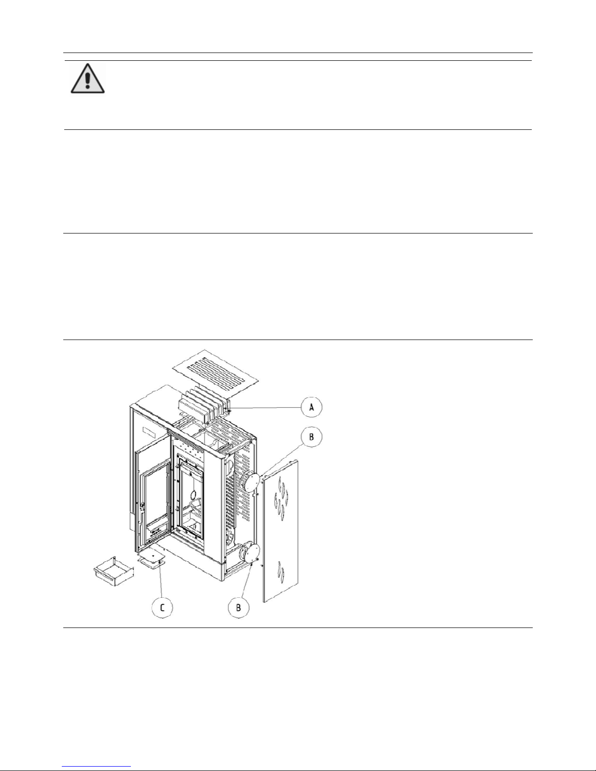
Fig. №. 6
A) Upper flue heat-exchanger
B) Side flue heat-exchanger
C) The space under the ash-pan
Page 20

20
The spaces to be cleaned:
A) Upper flue heat-exchanger:
1. Demount the upper cover.
2. Loosen up 4 pcs of screws of the cleaning cover of the heat-exchanger by means of a mounting spanner No.
10 (it is a part of supply) and demount the cleaning cover.
3. Sweep the heat-exchanger walls by a hand-brush and vacuum them by an ash vacuum-cleaner.
4. Mount back the cleaning cover of the heat-exchanger and fix 4 pcs of the screws.
5. Mount back the upper cover.
B) Side flue heat-exchanger:
1. Demount 2 pcs of the screws of the side cover by means of the hex key No. 3 (it is a part of supply)
2. Loosen up 3 pcs of the screws of the upper cleaning cover by means of the mounting wrench No. 10, and
demount the cover.
3. By means of a long brush (it is a part of supply), clean up the heat-exchanger by vertical strokes.
4. Loosen up 3 pcs of the screws of the bottom cleaning cover by means of the mounting wrench No. 10, and
demount the cover.
5. Suck up dust and soot by an ash vacuum cleaner.
6. Mount back the cleaning covers of the heat-exchanger and fix 6 pcs of the screws.
7. Mount back the side cover and fix 2 pcs of the screws.
C) The space under the ash-pan:
1. Open the glass door.
2. Open the cast-iron door of the heating chamber.
3. Take out the ash-pan.
4. Loosen up 4 pcs of the screws of the cleaning cover by means of the mounting wrench No. 8 (it is a part of
supply), and demount the cover.
5. Suck up dust and soot by an ash vacuum cleaner.
6. Mount back the side cover and fix 4 pcs of the screws.
7.5 Clean-up of the smoke-flues and the smoke-flue pipes
• Soot removal from the smoke-flues and the chimney has to be performed once a year only by a qualified
chimney-sweeper. Soot can be removed from the stove by means of wiping or brushing at the sides of the
heating chamber, or with help of an ash vacuum cleaner.
7.6 Clean-up of the cladding of the exhaust fan (it is not necessary, or only in
extraordinary cases)
• Disconnect the consumer from power supply!!!
• Loosen up 4 pcs of the screws.
• Demount the exhaust fan.
• Clean up by means of a hand brush and an ash vacuum cleaner the vanes of the exhaust fan, the smoke-flues
and the smoke-flue pipes.
• Mount separate parts back in opposite order. Be particular of electrical connections of the fan motor and their
correct placing.
Page 21
21
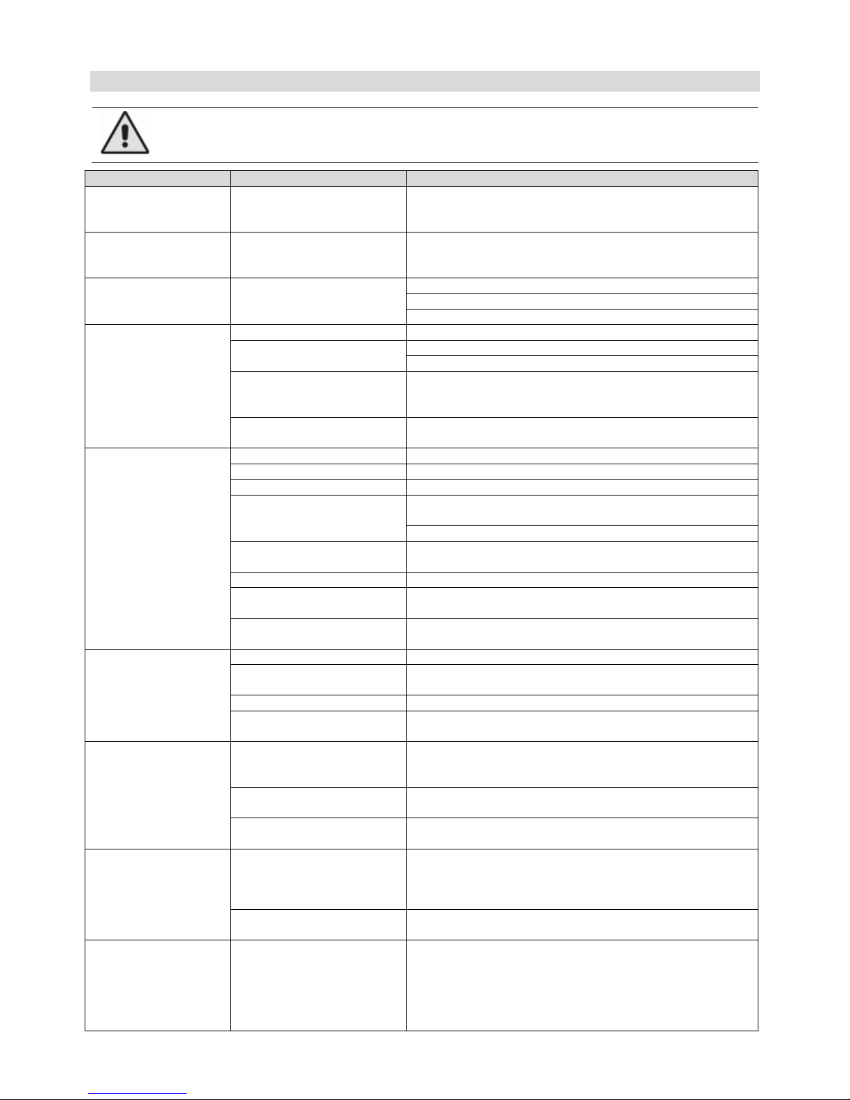
8 Possible causes of operation problems and their removal
In case of problems that you cannot remove by yourselves, contact the supplier of the stove
or a chimney-sweeper.
PROBLÉM
CAUSE
SOLUTION
Functionless
display
The equipment is not
powered
• Switch-on the switch situated on the rear side to the
position „1“
• Check that the power supply cord is properly inserted
The stove cannot be
„started“, the
display doesn’t light
The equipment is not
powered
• Switch-on the switch situated on the rear side to the
position „1“
• Check that the power supply cord is properly inserted
The stove cannot be
„started“, the
display lights
Low pressure to the display
• Hold the button ON/OFF for appr. 3 sec.
• Press more or several times to the display
• Replace the battery in the remote control panel
Insufficient draught
in the stove after
installation.
An obstacle in the chimney • Check the chimney
Impacted or closed central
air supply
• Check the central air supply
• Check that the central air supply is opened
Too strong draught of the
fume hood
• Connect the suction of combustion air to the central air
supply
• Correct a mode of the fume hood, decrease draught
Functionless exhaust fan
• Check functionality of the fan
• In case of inactivity, call service
The fire is hardly
kindled and after a
short time burned
out
Wet fuel • Burn by dry pellets, see chapter 5.3.
Low pressure in the room • Open the window near the stove for several minutes
Impacted central air supply • Check that the central air supply is opened
The central air supply can
be fully or partially blocked
• Disconnect the central air supply and try to burn the
fire only with help of air in the room
• Check that the central air supply is opened
The chimney shutter is
blocked by soot
• Check and clean the chimney shutter
The stove is sooted • Perform maintenance, see chapter 7
Low draught of the chimney
• Check the chimney
• Switch off the fume hood
Functionless exhaust fan
• Check functionality of the fan
• In case of inactivity, call service
Glass fumigation
and blackening
Wet fuel • Burn by dry pellets, see chapter 5.3.
The stove wasn’t enough
warmed up
• Warm up the stove to the operation temperature
Leaky door • Replace the door sealing
Functionless exhaust fan
• Check functionality of the fan
• In case of inactivity, call service
Smoke smell near
the stove
Backward chimney draught
as a result of atmospheric
conditions
• Wait for better weather
The door is not fully closed
or leaky
• Close properly the door
• Replace the door sealing
Functionless exhaust fan
• Check functionality of the fan
• In case of inactivity, call service
Fuel fire penetration
to the reservoir
Neglect of check and
cleaning
• In no case extinguish by water
• Close all air supplies for combustion, and, if possible,
cover up the chimney
• Contact the seller for inspection of the consumer
Defect temperature sensor
in the reservoir
• Call service
The fire in the
chimney
Neglect of check and
cleaning, heating by wet
wood
• In no cases extinguish by water
• Close all air supplies for combustion, and, if it is
possible, cover up the chimney
• Contact a chimney-sweeper service to assess the
state of the chimney after the fire
• Contact the manufacturer to inspect the consumer
Page 22

22
9 Liquidation of transporting packing, liquidation of the product after
the lapse of service life
Cardboard cover sorted communal waste
Plastic package sorted communal waste
Metal tightening band collecting center of metal waste
Ceramic glass collecting center for glass
Gasket mixed communal waste
10 Warranty conditions
The manufacturer grants a warranty for the stove for the period of 2 year from the date of selling. The
extended warranty is valid for the body of the welded furnace for the duration of 5 years from the selling
date, as well as for the cast-iron side heat-exchanger for the duration of 10 years. The warranty is limited to
the period of 6 months for mechanically loaded components, which are not firmly connected to the stove
(for example, sealing). The stove is produced and dispatched according to the valid drawing
documentation and in undamaged state. It is packed and handed over as a partial unit. The manufacturer
doesn’t reimburse costs, for which the warranty doesn’t relate to, as well as cost related to package and
transportation of reclaimed products. The manufacturer guarantees safety and function in accordance with
the instruction manual for the product for its whole service life. The warranty is granted to only one
customer. The warranty is related only to territory of the country where the product was bought.
The warranty comes into force in the moment of taking-over of the completely filled warranty certificate. It
is necessary to record in the warranty certificate the precise date of selling! Warranty service is provided
by the seller of your stove, until otherwise is agreed! In case of a reclaim, present a copy of the warranty
certificate and a document that confirms revision of the chimney.
Each announcement about defects has to be performed without delay after their discovery always by
means of phone calling and in written form.
In case of nonobservance of the above specified instructions, manufacturer’s warranty could be canceled.
Warranty doesn’t relate to:
•
defects caused by non-professional installation of the stove;
•
defects caused by wrong mounting and incorrect operation of the product, as well as defects caused
by incorrect maintenance;
•
defects caused by nonobservance of instructions specified in this manual;
•
defects that occurred at transportation (transportation on a pallet in the vertical position, non-closed
space, etc.);
•
defects caused by insufficient storage;
•
defects caused by extinguishment of fire in the furnace by a differ way than smooth residual burning
(for example, by water);
•
defects caused by using of insufficient devices at cleaning the glass or at damaging the glass as a
result of a mechanical stroke; the glass usually withstands temperature up to 750 °C;
•
defects caused by a natural disaster or an inevitable accident;
•
defects caused by using of insufficient fuel;
•
purposeful waste of the entire stove or its parts;
•
defects caused by insufficient selection of the stove (heating output);
•
defects caused by overheating (by operation with the output above the nominal output);
•
defects caused by a mismatched chimney, which has neither revision, nor sufficient draught;
•
spare parts that aren’t approved by the manufacturer;
•
any unauthorized modifications of the consumer.
This is valid for Czech Republic:
All information regarding warranty for the product, cancelling of the warranty and possibility of reclaiming
are specified on web-site: www.viadrus.cz
This is valid for foreign countries:
For all information regarding warranty for the product, cancelling of the warranty and possibility of
reclaiming, please contact your seller. Thank you.
The manufacturer reserves the right for changes performed within innovation of the product. The
manufacturer isn’t responsible for printing mistakes.
Page 23

23
Page 24
AGURO
VIADRUS a.s.
Bezručova 300
E-mail
| CZ - 735 81 | Bohumín
www.viadrus.cz
 Loading...