

Page 1

Copyright 2017 VIAAS, Inc. • 475-B Vandell Way, Campbell, CA, 95008 • +1.408.342.5570 • viaas.com
VIAAS
User Guide
If extra support is needed please call VIAAS Technical Support
at 408.342.5570, or email support@viaas.com
Page 2

1.
Overview . . . . . . . . . . . . . . . . . . . . . . . . . . . . . . . . . . . . . . . . . . . . . . . . . . . . . . . . . . . . . . . . . . . . . . . . . . . . . . . . . . . . . . . . . . . . . . . . . . 2
1.1 Release Notes . . . . . . . . . . . . . . . . . . . . . . . . . . . . . . . . . . . . . . . . . . . . . . . . . . . . . . . . . . . . . . . . . . . . . . . . . . . . . . . . . . . . . . . . . 3
1.2 What's New in VIAAS . . . . . . . . . . . . . . . . . . . . . . . . . . . . . . . . . . . . . . . . . . . . . . . . . . . . . . . . . . . . . . . . . . . . . . . . . . . . . . . . . . . 4
1.3 Getting Started . . . . . . . . . . . . . . . . . . . . . . . . . . . . . . . . . . . . . . . . . . . . . . . . . . . . . . . . . . . . . . . . . . . . . . . . . . . . . . . . . . . . . . . . 5
1.3.1 Recommendations . . . . . . . . . . . . . . . . . . . . . . . . . . . . . . . . . . . . . . . . . . . . . . . . . . . . . . . . . . . . . . . . . . . . . . . . . . . . . . . . 6
1.3.2 VIAAS Camera Installation Tips . . . . . . . . . . . . . . . . . . . . . . . . . . . . . . . . . . . . . . . . . . . . . . . . . . . . . . . . . . . . . . . . . . . . . . 7
1.3.2.1 VIAAS Bandwidth Calculator . . . . . . . . . . . . . . . . . . . . . . . . . . . . . . . . . . . . . . . . . . . . . . . . . . . . . . . . . . . . . . . . . . . 12
1.3.2.2 Camera Framing . . . . . . . . . . . . . . . . . . . . . . . . . . . . . . . . . . . . . . . . . . . . . . . . . . . . . . . . . . . . . . . . . . . . . . . . . . . . . 13
1.3.2.3 Camera Mounting . . . . . . . . . . . . . . . . . . . . . . . . . . . . . . . . . . . . . . . . . . . . . . . . . . . . . . . . . . . . . . . . . . . . . . . . . . . . 14
1.3.3 Bullet Camera Installation in an Outdoor Enclosure . . . . . . . . . . . . . . . . . . . . . . . . . . . . . . . . . . . . . . . . . . . . . . . . . . . . . . . 15
1.3.4 Bullet Camera Installation in a Heated Outdoor Enclosure . . . . . . . . . . . . . . . . . . . . . . . . . . . . . . . . . . . . . . . . . . . . . . . . . 21
1.4 Understanding Locations, Groups, and Roles . . . . . . . . . . . . . . . . . . . . . . . . . . . . . . . . . . . . . . . . . . . . . . . . . . . . . . . . . . . . . . . . 32
1.4.1 Understanding Locations . . . . . . . . . . . . . . . . . . . . . . . . . . . . . . . . . . . . . . . . . . . . . . . . . . . . . . . . . . . . . . . . . . . . . . . . . . . 33
1.4.2 Understanding Permissions and Roles . . . . . . . . . . . . . . . . . . . . . . . . . . . . . . . . . . . . . . . . . . . . . . . . . . . . . . . . . . . . . . . . . 35
1.4.3 Understanding Camera Groups . . . . . . . . . . . . . . . . . . . . . . . . . . . . . . . . . . . . . . . . . . . . . . . . . . . . . . . . . . . . . . . . . . . . . . 36
1.5 Administrative Functions . . . . . . . . . . . . . . . . . . . . . . . . . . . . . . . . . . . . . . . . . . . . . . . . . . . . . . . . . . . . . . . . . . . . . . . . . . . . . . . . 37
1.5.1 How to Manage Cameras . . . . . . . . . . . . . . . . . . . . . . . . . . . . . . . . . . . . . . . . . . . . . . . . . . . . . . . . . . . . . . . . . . . . . . . . . . . 38
1.5.2 How to Manage Locations . . . . . . . . . . . . . . . . . . . . . . . . . . . . . . . . . . . . . . . . . . . . . . . . . . . . . . . . . . . . . . . . . . . . . . . . . . 39
1.5.3 How to Manage Users and Roles . . . . . . . . . . . . . . . . . . . . . . . . . . . . . . . . . . . . . . . . . . . . . . . . . . . . . . . . . . . . . . . . . . . . . 40
1.5.4 How to Manage Camera Groups . . . . . . . . . . . . . . . . . . . . . . . . . . . . . . . . . . . . . . . . . . . . . . . . . . . . . . . . . . . . . . . . . . . . . 43
1.6 Camera Functions . . . . . . . . . . . . . . . . . . . . . . . . . . . . . . . . . . . . . . . . . . . . . . . . . . . . . . . . . . . . . . . . . . . . . . . . . . . . . . . . . . . . . 44
1.6.1 Configuration Panel . . . . . . . . . . . . . . . . . . . . . . . . . . . . . . . . . . . . . . . . . . . . . . . . . . . . . . . . . . . . . . . . . . . . . . . . . . . . . . . 46
1.6.1.1 How to Configure a Single Camera . . . . . . . . . . . . . . . . . . . . . . . . . . . . . . . . . . . . . . . . . . . . . . . . . . . . . . . . . . . . . . 47
1.6.1.2 How to Configure Multiple Cameras . . . . . . . . . . . . . . . . . . . . . . . . . . . . . . . . . . . . . . . . . . . . . . . . . . . . . . . . . . . . . . 49
1.6.2 Images Panel . . . . . . . . . . . . . . . . . . . . . . . . . . . . . . . . . . . . . . . . . . . . . . . . . . . . . . . . . . . . . . . . . . . . . . . . . . . . . . . . . . . . 50
1.6.3 NOW Panel . . . . . . . . . . . . . . . . . . . . . . . . . . . . . . . . . . . . . . . . . . . . . . . . . . . . . . . . . . . . . . . . . . . . . . . . . . . . . . . . . . . . . . 54
1.6.4 Timeline Panel . . . . . . . . . . . . . . . . . . . . . . . . . . . . . . . . . . . . . . . . . . . . . . . . . . . . . . . . . . . . . . . . . . . . . . . . . . . . . . . . . . . 58
1.7 Saved Events Functions . . . . . . . . . . . . . . . . . . . . . . . . . . . . . . . . . . . . . . . . . . . . . . . . . . . . . . . . . . . . . . . . . . . . . . . . . . . . . . . . . 62
1.8 How to Update Personal Information . . . . . . . . . . . . . . . . . . . . . . . . . . . . . . . . . . . . . . . . . . . . . . . . . . . . . . . . . . . . . . . . . . . . . . . 63
1.9 How to Use the VIAAS Mobile App . . . . . . . . . . . . . . . . . . . . . . . . . . . . . . . . . . . . . . . . . . . . . . . . . . . . . . . . . . . . . . . . . . . . . . . . . 64
1.10 Troubleshooting . . . . . . . . . . . . . . . . . . . . . . . . . . . . . . . . . . . . . . . . . . . . . . . . . . . . . . . . . . . . . . . . . . . . . . . . . . . . . . . . . . . . . . 66
1.10.1 How to Adjust from a Previous Release . . . . . . . . . . . . . . . . . . . . . . . . . . . . . . . . . . . . . . . . . . . . . . . . . . . . . . . . . . . . . . . 70
Page 3

Copyright 2017 VIAAS, Inc.
Overview
VIAAS is a cloud-connected, cloud-managed surveillance solution providing professional-grade features through a modern web browser or
mobile device. VIAAS maintains your privacy. Everything recorded on the camera is fully encrypted and remains encrypted at all times – on the
microSD card, on the Internet, and in cloud storage.
VIAAS cameras capture video when something happens, but do not record hours of nothing. For each video segment, object-based motion
tracking captures a key image. You can scan thumbnail images of events to locate an event of interest, then review the video with a single click.
These thumbnail images are effective even over low bandwidth connections. Cameras only send the small images in real time, but store
encrypted video locally on the microSD card. When more bandwidth is available, or when you want to watch a video, the video is uploaded to the
cloud. You can schedule specific times to upload the video, so it never critically impacts your network bandwidth.
Page 4

Copyright 2017 VIAAS, Inc.
1.
a.
b.
c.
2.
3.
4.
5.
6.
7.
8.
1.
2.
Release Notes
Version 5.0.0
This release improves security and modifies grouping and permission management to improve management for larger accounts, and to support
the next generation of cameras.
The primary changes include:
Expanded Groups. Previously groups were only available to an individual user and were not shared within the account. There are now
three types of groups:
Locations: Each camera must belong to a Location group. The Location group geographically relates cameras, so
configuration, monitoring, and administration are easier.
Only users with the Superuser role can configure Location groups.
Shared Groups: Cameras may optionally be added to multiple Shared Groups. Shared Groups are visible to all properly
authorized users in the account. Shared Groups are intended to relate cameras in other ways, such as by purpose, such as
"lobby cameras" and "outdoor cameras".
Only users with the Superuser role can configure Shared Groups.
My Groups: Cameras may optionally be added to multiple individual groups, called My Groups. My Groups are visible only to
the user who created them, and are intended to relate cameras in whatever way is most helpful for that user. A typical use is for
viewing a subset of cameras.
Any user can configure My Groups.
Managing Bandwidth by Location. Configuration options allow for bandwidth management based on the Location rather than by
camera. This is primarily to assist with alerting and for our next-generation cameras to share bandwidth more intelligently.
.Updated Camera Configuration Panel Updated to improve usability and allow for Location configuration.
.Permissions for Locations and Cameras Configure permissions, notifications, and bandwidth schedules for a Location, as well as for
separate cameras. In this way, a newly added camera may have assigned permissions as soon as you assign the new camera to a
Location.
.Permissions and User Roles Permission settings may be granted through Roles, so multiple users assigned to a single Role share a
single set of permissions. Assign a user to a Role to automatically set permissions to that Role.
. Camera Views based on Permission Users can only see cameras for which they have permission. If they do not have access to
cameras within a Location or Shared Group, they will not see the Location or Shared Group in the tree. For example, if a user has
access only to "Boston" cameras, they will only see the "Boston" Location and not any other Location.
.Single Level of Groups There is no longer any "nesting" of groups.
Security and Mobile Access. Improvements to security and mobile access.
If you are transitioning from a previous version of VIAAS, please note the following:
Each user in your account currently has custom permissions.
All cameras are currently assigned to a Default Location.
A user with the Superuser role should complete the transition process with these steps:
Review and modify Location group values (Location group name and camera assignment) for the cameras.
Update permissions and create roles so new cameras have permissions set up automatically.
Page 5

Copyright 2017 VIAAS, Inc.
What's New in VIAAS
New in Version 5.0
Locations and Roles
This release includes additional ways to administer cameras and users.
Cameras can now be grouped by . Certain changes you make to one location apply to all of the cameras within that location.location
Users can now be organized by . Changes you make to the role apply to all users with that role.role
Be sure to read Understanding Locations, Groups, and Roles for information on these new features.
Note that while these additions are useful for all VIAAS installations, they are most helpful for organizations with multiple cameras in multiple
geographic locations.
Page 6

Copyright 2017 VIAAS, Inc.
Getting Started
For information on physically setting up cameras, refer to the VIAAS Quick Start Guide, also provided in the box with your camera.
You should also refer to:
Recommendations
VIAAS Camera Installation Tips
Bullet Camera Installation in an Outdoor Enclosure
Bullet Camera Installation in a Heated Outdoor Enclosure
Registering for the First Time
The first time you log into VIAAS, you must provide the following information to complete your registration:
Serial number of the device, located on a sticker on the back of the device
*
Last four digits of the MAC address for the same device
*
Timezone
* If you have more than one device, choose the serial number for one device. Then choose the MAC address corresponding to the serial number
you chose.
Documentation Organization
This document is organized as follows:
Understanding Locations, Groups, and Roles Background on organization of cameras and
users.
Administrative Functions Managing users and cameras, along with
managing your account
(available only to users with Admin and
Superuser roles).
Camera Functions Viewing cameras, images, and recorded
events.
Also, how to configure cameras.
Saved Events Functions Viewing Events you have saved from
cameras.
Troubleshooting How to resolve common issues.
Where to Start
Administrators – Begin with , then adding users (Understanding Locations, Groups, and Roles Administrative Functions) and configuring
cameras (Configuration Panel).
Users – Begin with becoming familiar with the .Understanding Locations, Groups, and Roles and Camera Functions
Administrative functions are not visible to all users. Only users with specific permissions can view and change administrative settings.
Page 7

Copyright 2017 VIAAS, Inc.
1.
2.
3.
Recommendations
Read to familiarize yourself with the organizational structure of cameras and users.Understanding Locations, Groups, and Roles
The most straightforward method of getting started is:
Add cameras to the system. Define new locations if needed, otherwise, assign cameras to existing locations. (Refer to How to Manage
)Cameras
Define roles. (Refer to )How to Manage Users and Roles
Add users to the roles. (Refer to )How to Manage Users and Roles
Page 8
Copyright 2017 VIAAS, Inc.
VIAAS Camera Installation Tips
This article includes tips for VIAAS installation.
Site Preparation
VIAAS cameras require the following network infrastructure:
Firewall – Is there a firewall at the site, and if yes, how is it programmed? VIAAS cameras connect automatically to VIAAS
servers at. All VIAAS connections are outbound, so there is no need for any port forwarding. The cameras will use the following
ports, in the order listed, if they are open: 733, 443, 80.
Internet Bandwidth – Check that there is sufficient Internet bandwidth at the site.
For D1 resolution (720x480), you will need at least 512 kbps of upstream bandwidth and at least 100 kbps upstream per
additional camera. Using this metric, a facility with less than 1 Mbps upstream bandwidth can handle fewer than ten cameras.
For 720p HD resolution, the bandwidth requirement for video streaming and video/image file transfer to the cloud is about 2.5
times higher. Using this metric, ten cameras running 720p HD should have at least 3 Mbps upstream bandwidth. Use the
VIAAS Bandwidth Calculator (download here) for quick minimum bandwidth calculations.
Power over Ethernet (PoE) – Is the local network Power over Ethernet (PoE) enabled? PoE is requuired to power VIAAS cameras.
PoE can be provided to multiple cameras with a PoE switch, or to individual cameras with a PoE injector.
Some PoE switches only power half of their ports (many 8-port switches only power 4 ports) and some switches cannot supply
full power to all ports (for example, an 8-port switch that supplies 15W on any of 8 ports but can only supply 60W total).
Cameras running Wi-Fi need a Cat5 cable running PoE for power, even if the cable is not connected to the network.
Router and DHCP Server – Confirm there is a router and a DHCP server at the installation site. Some small businesses have just a
DSL or cable modem with one or two ports. Some of these devices lock to the first MAC address that they acquire and must be reset
from the access provider before they can work with a newly installed router.
By default, the DHCP server provides the IP addresses and gateway and DNS addresses. The DHCP server must have a
sufficient range of free addresses to support all of the cameras you are installing, or you must manually assign IP addresses to
each camera.
Wireless – For wireless installations, confirm there is an access point on site and within range. Determine if the cameras will share it.
If so, get the security information for the access point so you can configure the cameras to connect to it.
Make sure you have an account with VIAAS. The registration process adds the first camera to the account. You can then use
the Add Camera feature to input all of the other cameras into the account.
Registering New Cameras
Unpack the cameras and connect them to an Internet-connected PoE cable in your office, before you go to the installation site. You can
plug in several cameras at once. The cameras will connect to servers at VIAAS and download the latest firmware. This takes between
2-10 minutes, depending on the available bandwidth.
The cameras run their initiation and updates independently.
Make a list of the camera MAC addresses for future reference.
If you will use the cameras with Wi-Fi, you must configure the camera Wi-Fi settings while they are connected to the service with an
Ethernet cable.
Make sure you have all of the necessary mounting hardware, including the outdoor housings. Bullet cameras have versatile mounting
kits included in each box. Dome cameras mount to any flat surface with three screws and rubber washers (included).
If your network is not PoE-enabled or does not have enough PoE ports to support the cameras, you need to use PoE injectors (one per
camera) or a PoE switch.
Cable length is important. The maximum length of both Ethernet and PoE cables is 100 meters.
Installing Cameras
Hang the cameras securely and connect them all to the Internet. They take 2-3 minutes to boot and communicate with the servers at
VIAAS. You should have already let them load the latest firmware before reaching the installation site, as described above. If your
camera is not connecting to VIAAS, you might want to connect a laptop to the same cable that the camera is connected to and see if the
laptop can access the Internet. This will sort out most cabling issues and some, but not all, DHCP issues. You can also try the following
testing websites:
speedtest.net to check your network connection speed
pingtest.net to check your network connection speed and quality, especially the packet loss test
LED patterns – Each camera has LEDs that blink to represent specific conditions. The blinking patterns depend on the camera.
The VIAAS Dome camera uses single, multi-color LEDs. Get the latest information about LED pattern indications by
Camera Wi-Fi settings must be configured while cameras have a connection to the Internet before they can connect withwired
Wi-Fi.
See the Wi-Fi Configuration section toward the end of this document for detailed instructions.
Page 9
Copyright 2017 VIAAS, Inc.
1.
2.
3.
4.
5.
contacting VIAAS Technical Support at 408-342-5570. The indicator
lights on VIAAS Bullet cameras have the following patterns:
Light Pattern Meaning
Both lights blink together every 2-3 seconds Good connection
Right light is on; left light blinks Unable to obtain DHCP address
Both lights blink once per second
DHCP address obtained, but camera cannot connect to the
VIAAS servers
Aim – Once the cameras are all connected, you can adjust the camera aim. Aim each camera so it captures your target areas,
minimizing walls and sky.
For all models:
You can "flip" the image 180 degrees (upside down to right side up), in case you have to mount the camera upside down,
using the VIAAS Settings page in the browser.
VIAAS Bullet – Adjust the aim on the camera mount. Adjust the zoom using the lens (power zoom).
VIAAS Dome – Rotate the entire lens bracket in the camera base to aim the unit. Gently twist the knurled ring behind the
camera lens to achieve the best orientation.
IMPORTANT: DO NOT attempt to rotate the lens by turning the lens itself. This can cause the lens to break loose from its mount.
Camera Focus Tips
The cameras ship with default settings that should be adjusted after installation to maximize performance. It is best to perform the adjustments
after the cameras have been running for a few days. This allows some event and video history to build, which can be used for fine tuning.
VIAAS Support staff can examine each camera's performance and help you refine the filters and motion detection settings.
Focusing VIAAS Bullet and Dome Cameras
To focus VIAAS Bullet and Dome cameras:
Open VIAAS in your browser and navigate to the Settings page for the camera you want to focus.
On the Settings page, click Zoom/Focus.
If you are not already in Auto Mode, click Switch to Auto Mode.
a. In Auto Mode, adjust the zoom and then click Focus so the camera will focus itself.
b. In the browser window, you should see the frame come into focus and lock automatically. Click Done.
Click Save & Exit to save your focus settings on the camera. Please be patient. This process may take 10-20 seconds.
Optionally, when you return to the NOW Panel in the view for that camera, click Go Live to see that the scene is in focus and the zoom is
optimized.
In some environments, the camera may have difficulty focusing automatically. If the camera is unable to focus automatically, click Switch to
. There, you can make small adjustments to the focus manually. Please be patient because the camera view you see is delayedManual Mode
10-20 seconds, due to network and server latency. If the delay is too long, close the focus utility and check the camera focus in Go Live mode.
Repeat the focus sequence if needed.
Installing an IR Illuminator
If you are installing an IR illuminator ring on the VIAAS Bullet camera, remove the sticker covering the contacts at the front of the
camera. Find the contact pads in the camera, and then look where the spring pins in the IR ring will contact the pads. Line the pins up
over the pads and snap the ring in place. Take care that you do not install the ring with both pins on one pad. The IR ring will not operate
under those conditions.
Test the IR ring. The ring only receives power when the camera is in Night Mode. To put the camera in Night Mode, hold your hand over
the lens for about 2 minutes, the LEDs will blink, and then you will hear the click as the exchanger flips the IR filter out of the optical path
and the camera switches to Night Mode. Look at the IR ring with your cell phone camera. If it is functioning, you will be able to see the
LEDs glowing. The human eye cannot see the IR ring illumination, so using a cell phone camera is helpful.
Outdoor Installation
The VIAAS Dome camera is rated for both indoor and outdoor use.
If you adjust the zoom for framing, you must also adjust the focus.
Please be patient when adjusting the focus and zoom on the cameras. It takes several seconds for the commands to execute on the
camera and for the results to appear in the browser window.
Page 10
Copyright 2017 VIAAS, Inc.
The VIAAS Bullet camera is not weatherproof. To install them outdoors, you will need housings. Contact VIAAS Sales for assistance in
purchasing outdoor housings. For particularly cold or hot climates, VIAAS Sales can suggest housings with heaters and fans.
Most of the housings come with a ¼-20 screw with a low profile head for attaching the camera to the sled. Be sure to use that screw; any
other screw could prevent the sled from seating in the track.
Be sure to seal the conduit hole in the housing to prevent dust or insects from getting into it.
Put the lens very close to the glass, but not quite touching it. The lens will need a little room to move when zooming or focusing. This
prevents insects from getting between the glass and the lens and seeing the reflection of the LEDs in the image. LEDs can be turned off
in the camera settings tool to prevent reflection issues.
As described above, focus the camera outside the housing, then snap it in.
Refer to the following articles for details on this these types of installations:
Bullet Camera Installation in a Heated Outdoor Enclosure
Bullet Camera Installation in an Outdoor Enclosure
Camera Configuration
Nearly all camera settings, except physical positioning, are done from the camera Settings page in the VIAAS web interface. In the NOW
Panel, click the small gear icon in the upper left corner of the camera view. This opens the settings window for that camera.
Bandwidth Settings
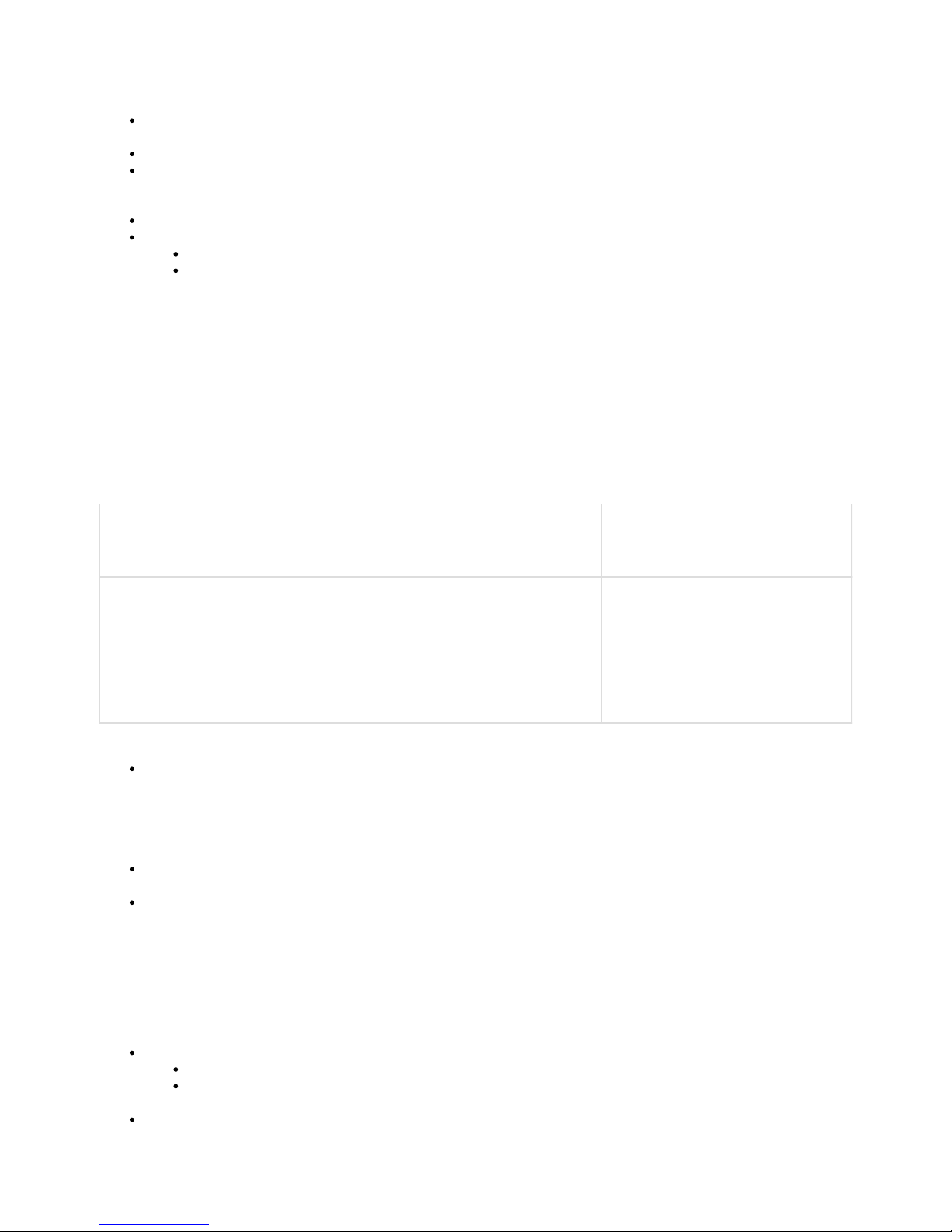
This table summarizes suggested bandwidth settings.
You can select for D1 or 720p HD. Choose the settings and bandwidth management that allow the cameras to operate optimally over the local
network.
For a detailed description, continue reading the article after the table.
Default Bandwidth D1 resolution cameras
720p HD cameras
100 - 200 kbps
250 - 600 kbps (about 2.5 times amount for
D1 resolution)
Maximum
D1 resolution cameras
720p HD cameras
500 kbps
1250 kbps (1.25 Mbps)
Unlimited
Do not use this setting.
When the SD card fills up, the camera might
consume all of your network bandwidth when
attempting to upload videos.
Details about Bandwidth
Choosing a default bandwidth. Cameras work well with a default bandwidth of 100 or 200 kbps. Cameras in the field typically have a
duty cycle of less than 25% (recording less than 25% of the day), and are often under 15%. The camera records at 380 kbps (1 Mbps in
720p HD) when it detects motion. If it detects motion 25% of the time and it has 100 kbps of default bandwidth, it can smoothly upload
images to VIAAS servers throughout the day and night. 720p HD cameras should be allocated about 2.5 times as much bandwidth as
those running in D1 resolution. As a general rule, give the cameras as much bandwidth as you can afford, up to 500 kbps in standard
resolution or 1 Mbps in 720p resolution. This will extend the life of the SD cards.
Choosing a maximum bandwidth. In D1 resolution, set the max bandwidth to 500 kbps.
For 720p HD resolution, multiply the bandwidth requirements by 2.5 for live streaming and video file transfer to the cloud.
Busy scenarios. In some cases, you cannot set the camera's default bandwidth high enough to upload all of the video during the day.
For example, in a busy restaurant or retail shop, the cameras might average 20% duty cycle (recording 20% of the day), so if you have 6
or 8 cameras running on a modest broadband connection, they might use nearly all the available bandwidth, leaving little for point-of-sale
devices (e.g., credit card machines) and other essential networked equipment.
In these busy situations, you can set camera bandwidth utilization to be very low during business hours and then throttle it up when the
network is not needed by the customer, typically late at night. For example, to minimize use of the customer network during busy periods,
you can set each camera's bandwidth to 50 kbps or 100 kbps during business hours. When the restaurant or retailer is closed, you can
set the cameras to run at 500 kbps for several hours to empty their SD cards. Set this feature carefully to achieve the best performance
for your needs.
Schedules.
When you set a schedule, remember to click , so the schedule runs every day. Otherwise, it will run only once. Daily
Avoid setting rolling schedules, where one camera gets high bandwidth for an hour, then another camera gets the high
bandwidth, then another camera, and so on. Give all of them the entire night, or off-peak period, and they will work through it.
Avoid cascading switches with a slow connection. If you have a slow Internet connection, do not cascade switches. If you have one
switch plugged into another, the cameras on the downstream switch get a fraction of the bandwidth the cameras on the top switch
receive.
Page 11
Copyright 2017 VIAAS, Inc.
1.
2.
3.
4.
5.
a.
b.
6.
7.
8.
9.
10.
Preview Mode. Put the cameras in Preview Mode to view them on the camera browser. Nearly all organizations want this "live view"
capability for active monitoring.
Set "dead zone" cameras (for example, storage, back door, basement, IT closet) to a slower preview rate.
Set "active zone" cameras ( , lobby, dining room, manufacturing, showroom) to one frame every two seconds orfor example
more for near-motion video monitoring.
Camera Motion Detecting Settings
VIAAS Bullet and Dome Cameras
For VIAAS Bullet and Dome cameras, motion detection is set using Regions of Interest. On the Settings page of the web interface, scroll
down to the Zone Editor section. Click Create Zones to open a tool to draw boxes around "Regions of Interest" where motion should be
detected, and other motion in the image can be ignored. This is useful for a camera in a lobby with a busy street behind it. Using the tool, you
would draw a box around the lobby area, the Region of Interest, but exclude the street. That way, activity in the lobby triggers the motion
detection and video recording, but traffic on the street would not.
For all cameras, use the following tips for motion detection:
Tune out unwanted motion. If you have video clips that were created based on background motion, you can tune the settings to fix
that. Play one of these clips from within the Images or Timeline panel. While the clip is playing, click player menu icon in the
lower-right corner of the player and select Show Motion. Red boxes will appear in the video, showing where the camera picked up
motion. It could be actual motion, or just things like lights, shadows, or outside traffic. You can make adjustments by creating zones to
reduce unwanted recordings and alerts.
Tune the camera settings carefully. Maxing out the settings can reduce the system performance. The cameras have a high degree of
adjustability that can be very effective if set systematically and thoughtfully.
Set alerts to actively monitor camera, event, and recording activity. VIAAS can send you email notifications of events or if the
camera goes offline. The system can also email you if it detects motion during a scheduled time period. In most conditions the motion
detection is very accurate and these "off-hours motion alerts" may be very helpful.
Wi-Fi Configuration: VIAAS Bullet and Dome Cameras
If possible, configure the camera Wi-Fi settings using the Wi-Fi network the camera will use when it is operating normally. It is possible, but more
challenging, to perform this configuration remotely. If you perform the configuration remotely, be sure you have the key information for the Wi-Fi
network the camera will use, as described in Step 6 below.
To configure Wi-Fi for the VIAAS Bullet and Dome cameras:
Plug the camera into a wired Internet connection with power over Ethernet. Log into VIAAS using a web browser.
Open the Settings page for the camera.
Scroll to the bottom of the camera Settings page. For Interface Preference, select Use Ethernet, Wi-Fi Backup.
At the bottom of the Settings page, click Configure Wireless. A new window opens.
If you are within range of the network the camera will use:
Change the to and click . A list of available networks should appear.Mode DHCP Scan
Select the correct network from the list. The window opens and you can enter the NetworkWireless Network Configuration
Name, Network Authentication, Data Encryption, and Network Key. You only need to enter a pass phrase if you are selecting a
network from the list.
If you are not within range of the Wi-Fi network the camera will use:
Click to manually enter the network and security settings (Network Name, Network Authentication, DataConfigure Manually
Encryption, Network Key). The camera cannot work without the exact Wi-Fi settings. When you are within range of the Wi-Fi
network, this information will populate automatically, reducing the risk of error.
After you have entered the network and security settings, click Apply. Click Test Wi-Fi to see if the connection works. Click Done to
save the settings and close the window.
If possible, check the list on the access point to verify that the camera is connected. If you do not have access to the list, reopen the
VIAAS Wi-Fi configuration page you opened in Step 4, and see if it says connected and displays the selected network highlighted in
green.
Near the bottom of the camera configuration page, under Interface Preference, change the setting to Use Wi-Fi, Ethernet Backup. At
the top of the Settings page, click Apply to save the settings. After you have entered and saved the settings to the camera, you can
install and power on the camera. It will connect to the Wi-Fi network.
Check local laws before turning audio on because it may be illegal in some jurisdictions.
Caution
VIAAS surveillance cameras are not intended to replace security alarm systems or intrusion detection devices.
Page 12
Copyright 2017 VIAAS, Inc.
10.
Contacting Technical Support
For assistance, contact VIAAS Technical Support.
Call 408-342-5570 between 8:30am-5:30pm Pacific time
Email support@viaas.com
Visit VIAAS Technical Support
Important
Please allow about a minute for the settings to save to our servers and in the camera before unplugging the camera from the
wired Internet connection. If you disconnect the camera before the settings are applied, the camera will not have the correct
Wi-Fi settings and you will have to connect the camera to a wired Internet connection for a couple of minutes until the settings
are saved.
Page 13
Copyright 2017 VIAAS, Inc.
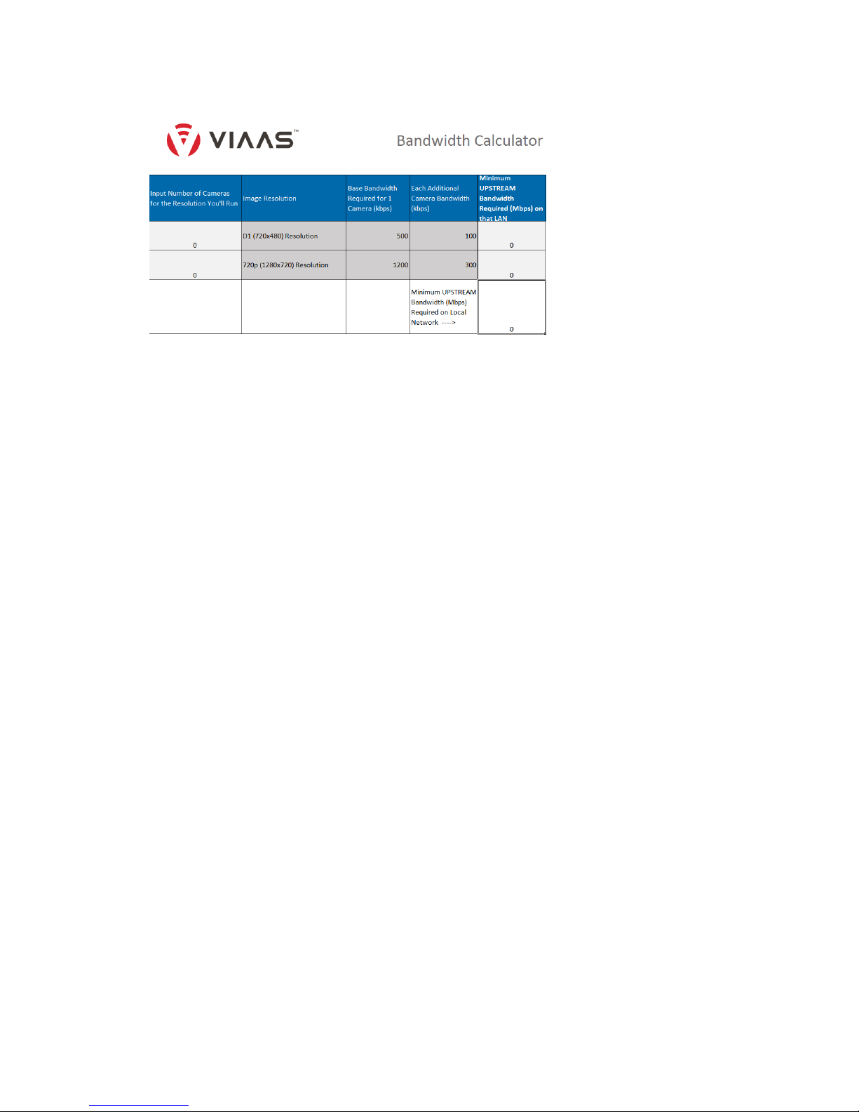
VIAAS Bandwidth Calculator
Use the VIAAS Bandwidth Calculator for quick minimum bandwidth calculations.
Click to download the VIAAS Bandwidth Calculator.
Refer to VIAAS Camera Installation Tips for information on bandwidth requirements.
Page 14
Copyright 2017 VIAAS, Inc.
Camera Framing
When deciding how to mount your VIAAS camera, consider the topics in this article.
What do you want to see?
Deciding what you want to see is really a question of your goals. If you want to be able to recognize who is coming in and out of your lobby, place
the camera someplace where it is likely to get a facial shot as people enter or exit. If you want to watch cars in your parking lot, decide if you
need to be able to read license plates and mount the camera appropriately. You can usually make these decisions easily, once you think about
what you want to see on a video a week after the event occurred.
How can you best use your camera to accomplish that?
From a technical point of view, there a two issues to consider – image quality and event triggers.
Image Quality
Range of Lighting
For reasonable image quality, you need light – the better the light, the better the image you will capture. Strive for light that is bright and consistent
across the entire frame. VIAAS Ultra High Dynamic Range (UHDR) is relatively immune to lighting issues. However, it is important to know it
works by first making sure that the darkest areas of the image are good enough, then extending the dynamic range to cover the brightest areas. If
you have poor image quality, the best fix is to increase the light in the darkest areas (<10 lux) or to adjust the camera framing to eliminate dark
areas.
Sharp Transitions in Lighting
Try to avoid sharp transitions in frame lighting. This is most often encountered as somebody opens a tinted door to a brightly lit outdoor area,
flooding the room with light. In this situation, consider pointing the camera away from the door and capturing images as people leave, before they
open the door on the way out.
Low Light
If you want very good performance at night with very low light, use an IR illuminator. They are inexpensive and very effective. VIAAS works well in
Night Mode on its own, down to about 1 lux, and has usable images down to 0.1 lux. Almost any "legal" indoor workplace lighting including
emergency lighting will work well. If you want to capture images of a deer in your backyard by starlight, it would help to use an IR illuminator.
Capturing Motion Events
VIAAS cameras use object-based motion detection to capture images when things happen, and to ignore what does not matter. Cameras are
tuned to fire aggressively, under the assumption you do not want to miss anything.
A common issue is that you have things in the foreground you want to capture (e.g., people on a sidewalk) but there are also things in the
background that move a lot (e.g., cars on the street). You end up with a huge number of images of cars and a few of people. Random small
movement, such as waves or trees in the wind, are filtered effectively. The only issue is relatively large things moving coherently.
VIAAS events offer two tools on the Configuration Panel to help you:
Zone Editor – Allows you to create up to three regions of interest. Recording will trigger if there is motion in any region, but will ignore
motion outside the region(s).
Sensitivity – Sensitivity works if you have different-sized objects. For example, the people in foreground are large, and the cars in
background are small.
If your situation does not fit into one of these two categories, you need to re-frame the image. Some options include:
Zoom in to narrow the field
Mount the camera higher or lower to get better separation
Re-aim the camera to eliminate one of the motion types
Page 15
Copyright 2017 VIAAS, Inc.
Camera Mounting
Refer to the Quick Start Guide you received in the box with the camera for most instructions. This article is an additional discussion of how to
physically hang the camera.
Choosing a Location
Determine where you will mount the camera.
Consider the following factors:
what will the camera look like and how will people react to it?
how easy will the installation be?
where will you get connectivity and power?
how well will the camera function to provide you with the images you want?
Be sure to read the article on Camera Framing as part of determining the camera's location.
Getting the Equipment Ready
After you have picked a location, get your equipment ready. The steps from here vary a little between drop ceiling install and screwmount.
Drop Ceilings
It is relatively easy to mount a camera on a drop ceiling.
For drop ceilings, you use the "scissor mount" to attach the camera to one of the drop ceiling rails. You do not need any tools, though a large pair
of pliers (channel lock type) can be useful.
While on the ground, assemble the camera mount. In most situations, one long extender and one short extender work well. Attach the extenders
to the scissor mount and attach the mount head to the other end. Screw everything together firmly by hand. You do not want any of these
connections turning when you attach the camera later, but also do not break anything.
DO NOT ATTACH THE CAMERA NOW.
Open the scissor mount completely (so the flanges are as far apart as possible). Finally, pick the rail you will mount to. It is better to have the rail
largely in line with the direction of the camera aim. Now you are ready to go up the ladder.
Attach the scissor mount to the rail. It works well to rock the mount slightly in one direction and work one side over the rail, then rock it flat and
close the mount. The channel lock pliers come in handy for closing the mount. If it is really tight, you can use a flat screwdriver to open the
flanges a little. Continue with , described below.Attaching the Camera
Screw Mount
To mount the camera on a solid wall or ceiling, use the screw mount base. If you are installing into drywall or plaster, you can use the included
screws and inserts. You will also need:
drill with a 1/4" or 6mm bit
pencil
Phillips head screwdriver
If you are installing into a different material, use appropriate screws and attachment techniques. In any case, you will follow these steps:
Mark the mount points using the base
Drill for the screws/inserts
Attach the base
Attach the mount to the base
Attach the camera.
With the base and a pencil, climb up and mark the mounting holes, then drill. Push in the inserts until they are flush, then attach the base with the
screws.
Assemble the rest of the mount before you attach it to the base. Pick your extenders – for ceiling mount, one long and one short work well and–
screw them together with the camera head. Now attach the assembled mount to the base. Make sure everything is fairly tight. You do not want
any of these joints twisting as you finish the install. Continue with Attaching the Camera, described below.
Attaching the Camera
The final step is attaching the camera. Climb up and install the camera. Loosen the set knob so the camera screw moves freely. Turn the head
itself until the slot is parallel to the direction of the camera aim because you will need to tilt the camera. To attach the camera, aim it about where
you want, push it onto the screw and turn the screw, holding the camera in place. Keep going until it is tight. Now make sure the camera can tilt
(align the slot with direction of the camera). Tilt the camera to about the right angle, and tighten up the set knob. Plug in your
Power-Over-Ethernet and you are done.
Page 16
Copyright 2017 VIAAS, Inc.
1.
2.
3.
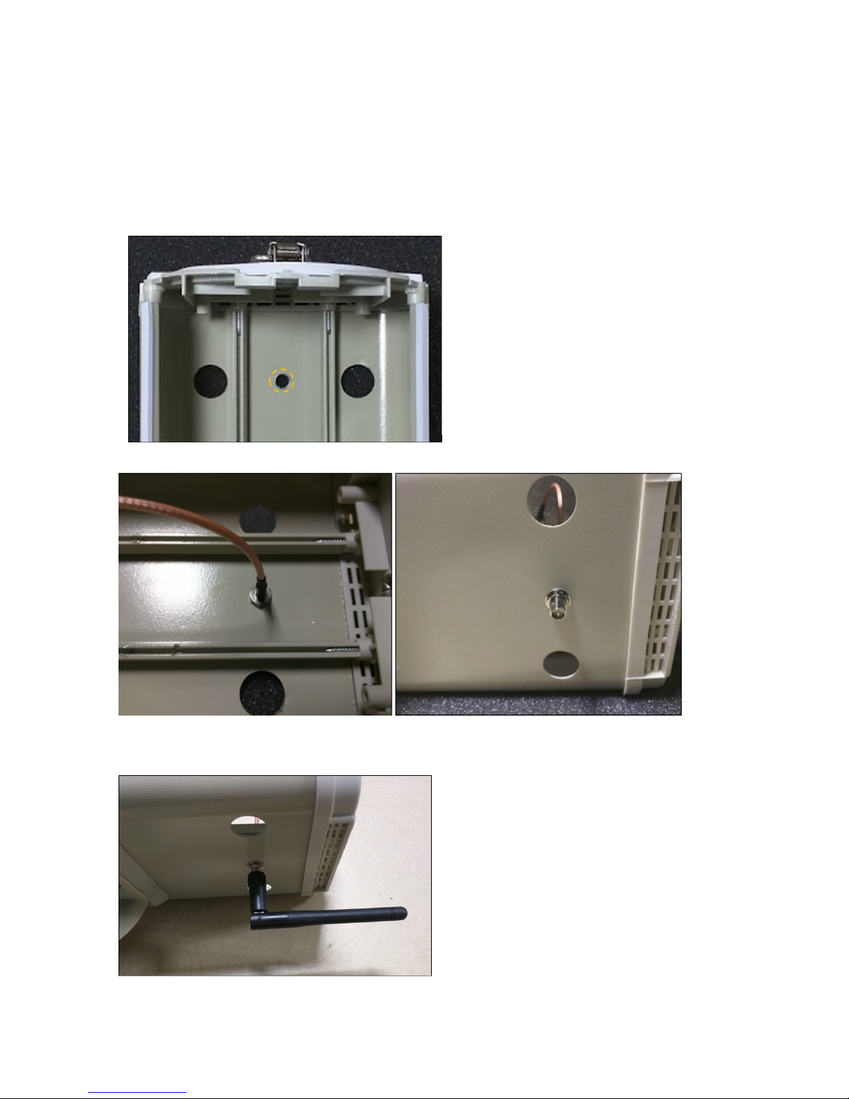
Bullet Camera Installation in an Outdoor Enclosure
This document explains how to install a Bullet Camera into an outdoor enclosure.
Step 1: Install the Wi-Fi Antenna (Optional)
If you will be installing a Wi-Fi antenna, complete the steps in this section.
Otherwise, proceed to the next section, Ethernet Cable Installation.
Open the enclosure.
Drill a ¼" hole toward the back of the enclosure. Remove all burrs and cuttings.
Install the RP-SMA extension cable into the hole in the back, .using the supplied lock washer and nut
This figure shows a completed antenna.
Note: Point antenna straight down (vertically), for best results. Do not position antenna horizontally, as shown.
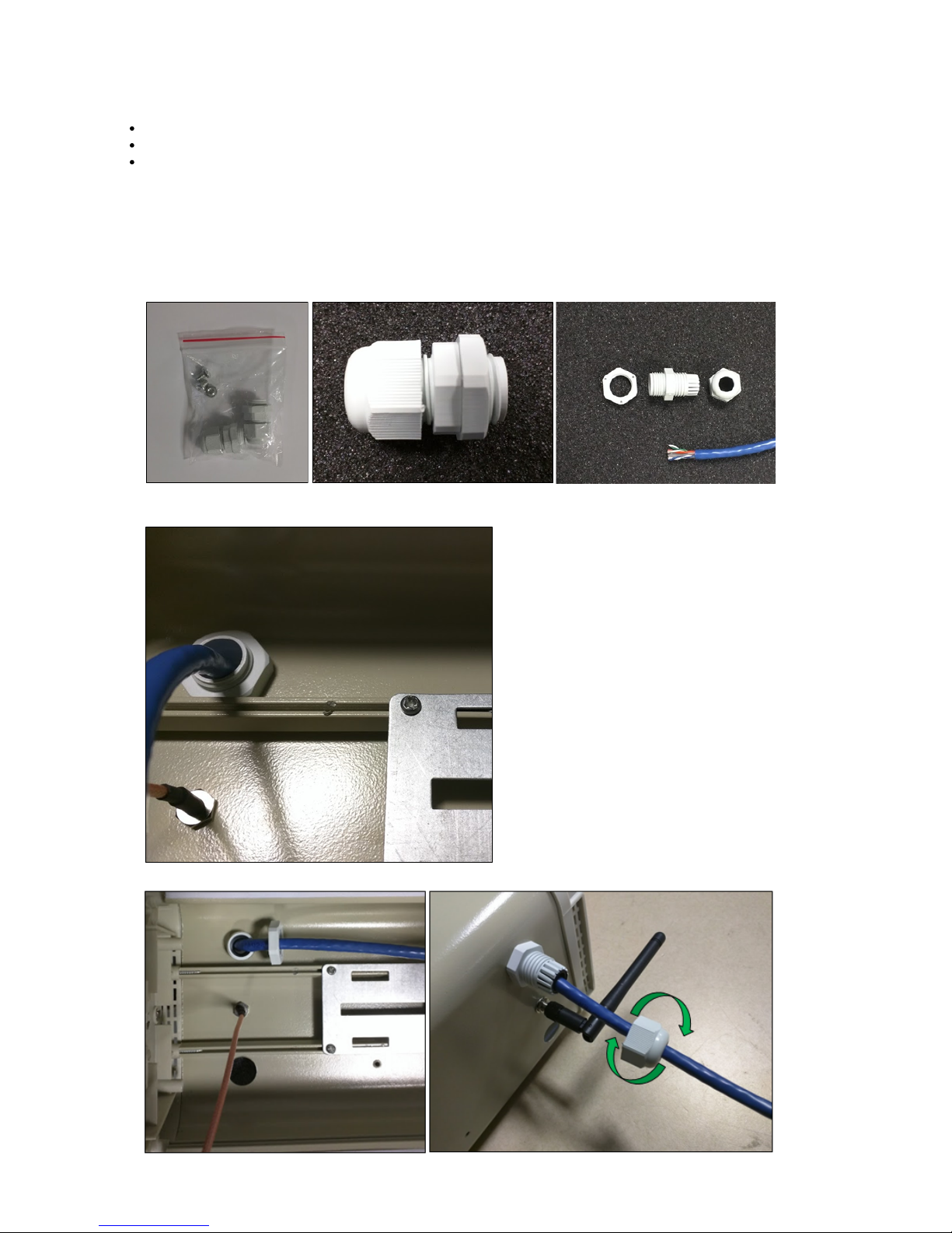
Step 2: Install Ethernet Cable
Page 17
1.
2.
3.
4.
5.
Copyright 2017 VIAAS, Inc.
Ethernet cable provides power to the camera, regardless of whether Wi-Fi is used to transmit data.
Use the following recommendations:
Power over Ethernet (PoE) – either an 802.3af PoE supply or a 48VDC power supply
Current – 125mA, about 6 watts
or a flexible conduit with indoor rated cable inside. Ethernet cable – either outdoor rated (described here)
Place the PoE power supply in a location suitable for the device. Ensure that you will power the supply in accordance with all applicable
safety and electrical codes.
Run a CAT5 or better Ethernet cable from the output of the supply.
Locate the cable gland in the enclosed parts bag.
Note that the supplied gland may be designed for a substantially larger cable than what you are using. The purpose of the gland is to
provide strain relief. If the cable gland is too large for your cable, you can wrap a section of the cable in electrical tape to increase its
girth.
Install the cable gland or flexible conduit fitting in the camera enclosure, using the provided hole at the rear of the enclosure.
Route the cable into the enclosure through the cable gland.
Page 18
Copyright 2017 VIAAS, Inc.
6.
1.
2.
3.
Terminate the cable with an RJ-45 connector so it can be connected to the camera, as shown below.
Continue with the following section, Camera Installation.
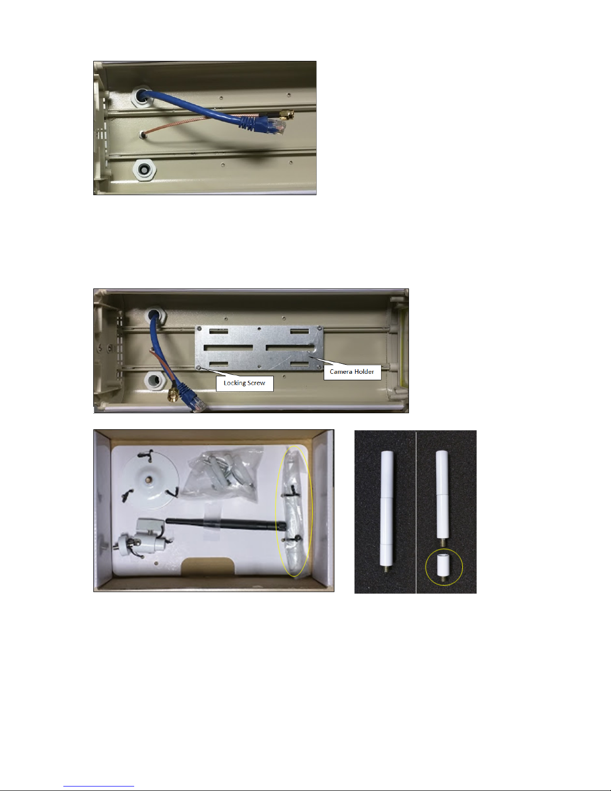
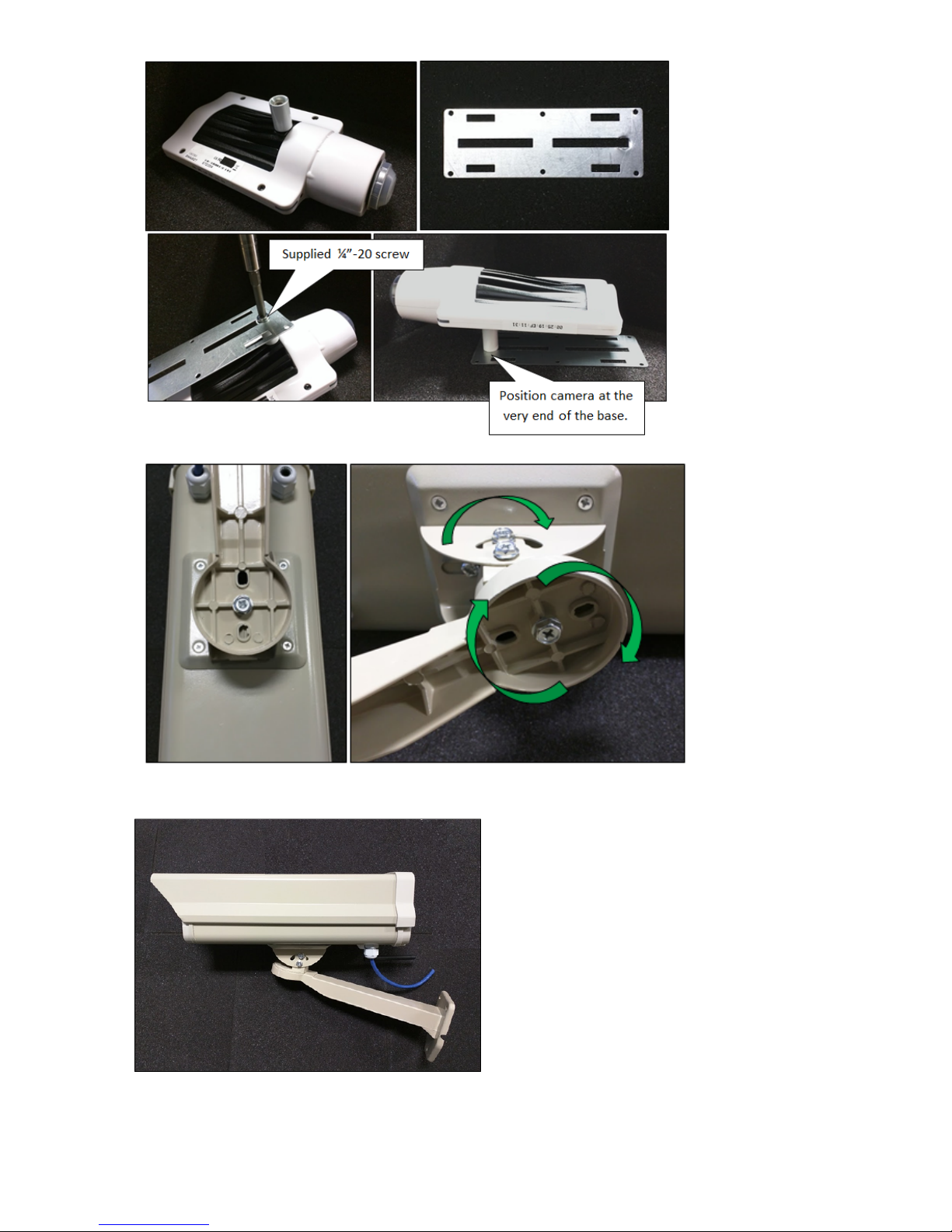
Step 3: Install the Camera
To install the camera:
Remove the locking screws that keep the camera holder in place. Remove the camera holder.
In the original camera packaging, locate one of the white metallic spacers.
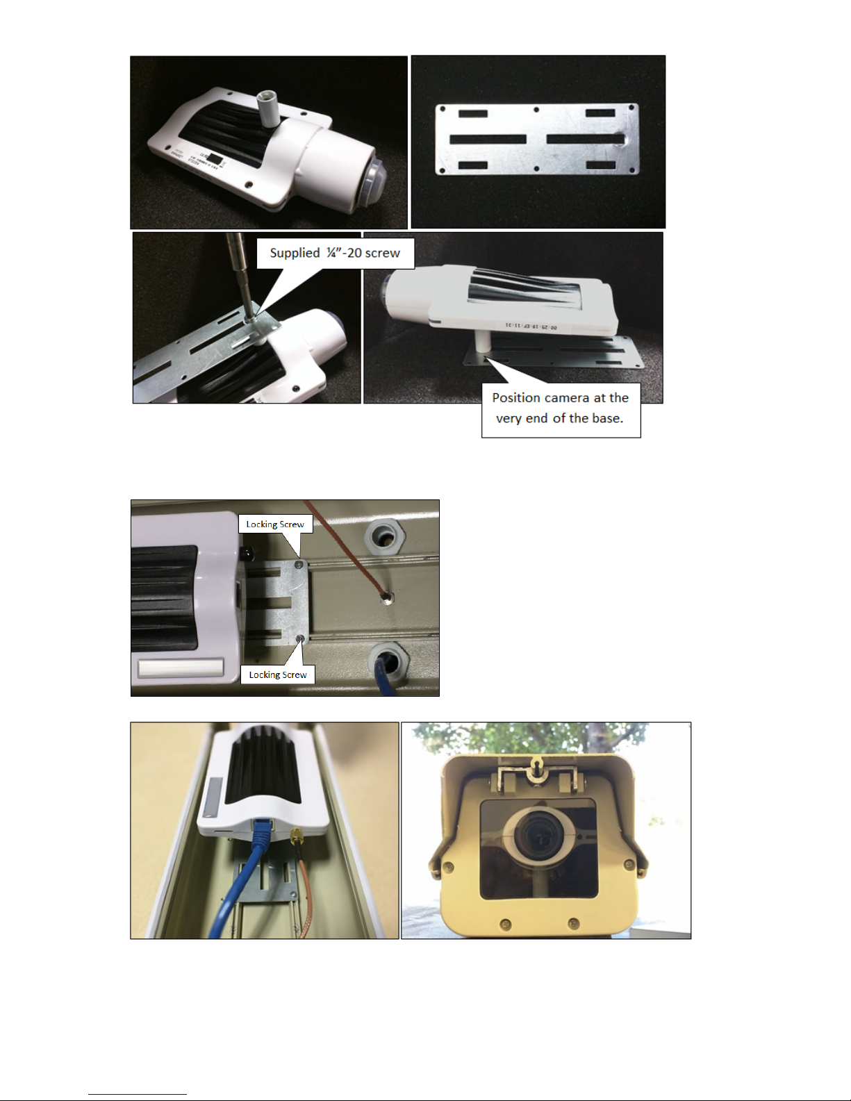
Mount the camera to the holder as shown, using the ¼"-20 screw that came in the parts bag and the white metallic spacer from the
original camera packaging.
Page 19
Copyright 2017 VIAAS, Inc.
4.
5.
6.
Snap the camera and holder back into the enclosure. Position the camera so the lens is about ¼" - ½" behind the front glass. If the lens
Ris too close, the zoom mechanism will hit the glass. If the lens is too far, the wide angle of the lens will see the edges of the enclosure.
eplace the locking screws to fix the camera holder in place.
Connect the Ethernet cable to the camera. If you are using Wi-Fi, connect the RP-SMA extension cable to the camera.
Mount the enclosure in a suitable location.
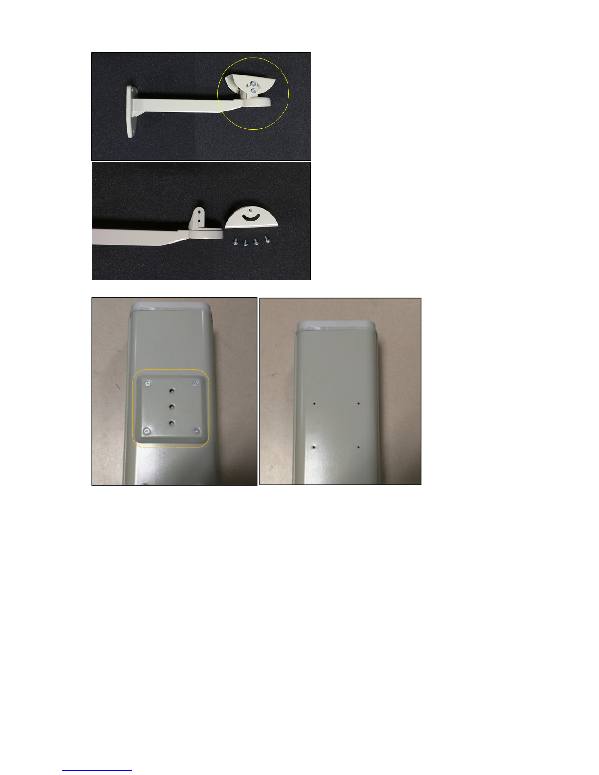
Step 4: Assemble the Mount
To assemble the mount:
Page 20
Copyright 2017 VIAAS, Inc.
1.
2.
3.
Disassemble the highlighted section of the arm mount.
Remove the base from the bottom of the case.
Attach both bases together using the supplied screws, then install it back to the arm mount.
Page 21
Copyright 2017 VIAAS, Inc.
4. Install the full arm on the camera case, and adjust the angles as needed.
This figure shows a completed arm mount installation.
The unit is now ready to be installed in the location you have chosen.
Page 22
Copyright 2017 VIAAS, Inc.
Bullet Camera Installation in a Heated Outdoor Enclosure
This document explains how to install a Bullet Camera into an outdoor enclosure with environmental controls. It does not cover the physical
mounting of the enclosure mount or running the conduit.
Much of the installation work is best done on the ground. You can complete most of the steps in this article before you get to the installation site.
Only the final step requires you to be at the final installation location.
PART I: COMPLETE BEFORE MOVING TO THE INSTALLATION LOCATION
Understanding the Parts
You must run two separate cable wires:
for the camera – CAT-5 or better
for the enclosure's control printed circuit board (PCB) – 24 VAC
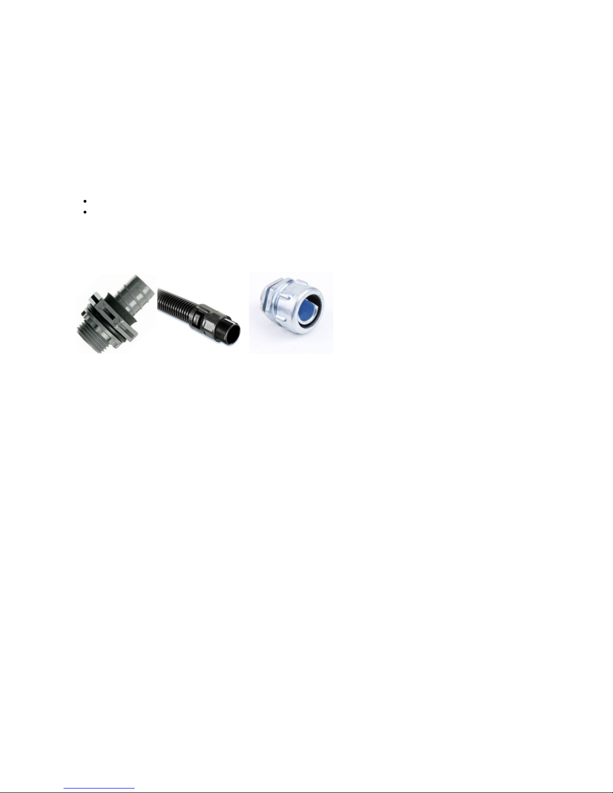
The images in this article show the use of a cable gland, which shipped with the enclosure. Flexible conduit systems generally provide better
results. It is up to the installer to adapt their chosen conduit system to the enclosure.
The enclosure includes an opening that accepts industry-standard ½" conduit termination, such as those shown here.
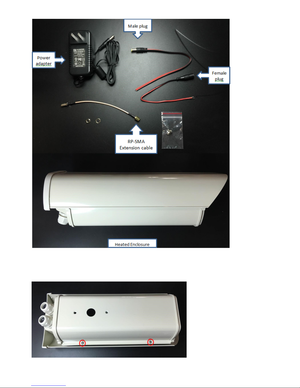
Supplied Items
Page 23
Copyright 2017 VIAAS, Inc.
Step 1: Remove the Enclosure Lid
To remove the top, remove the two highlighted screws.
Page 24
Copyright 2017 VIAAS, Inc.
1.
2.
1.
2.
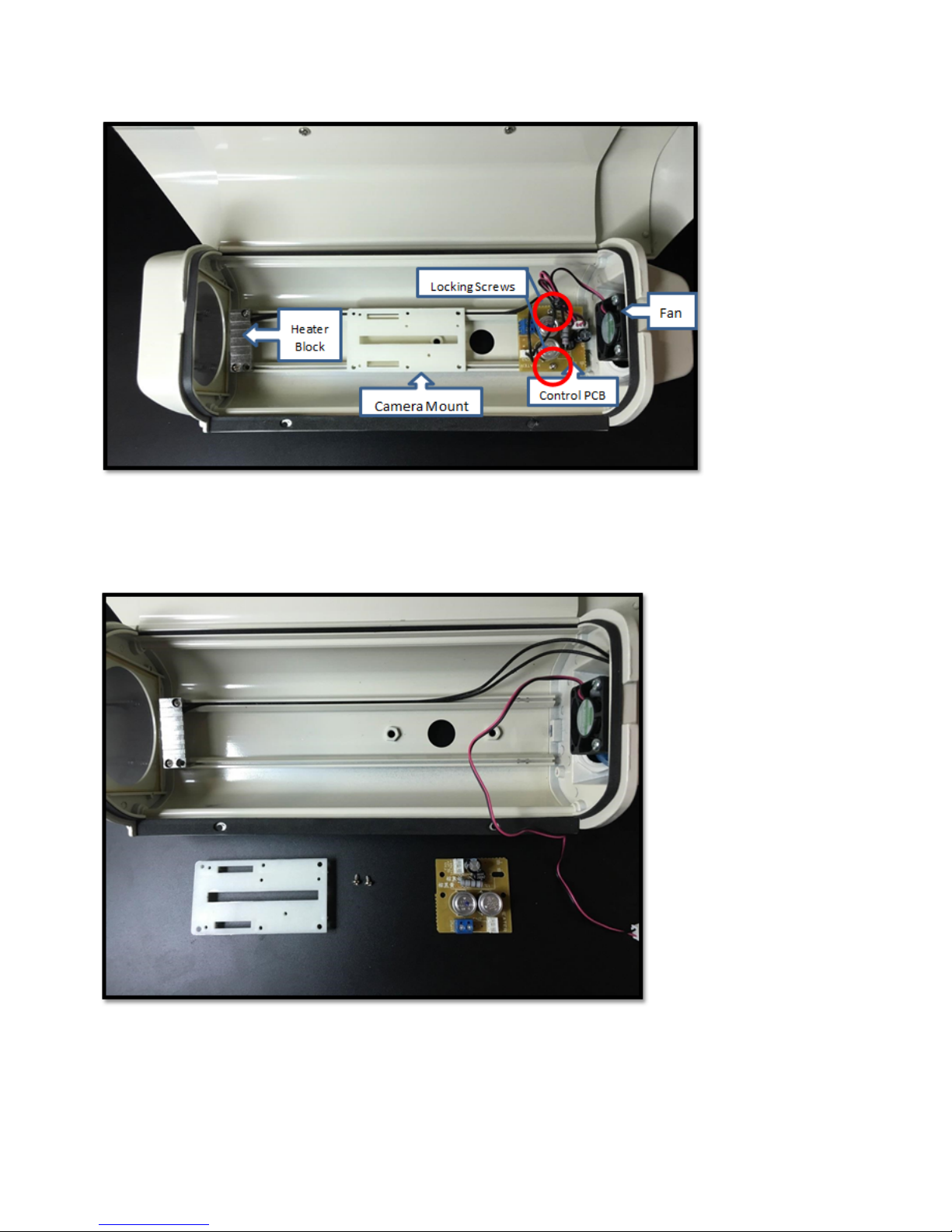
Step 2: Become Familiar with the Parts Inside the Enclosure
Take a moment to familiarize yourself with the parts inside of the enclosure.
Step 3: Remove Camera Mount and Release the Control PCB
Remove the camera mount by pulling the mount upward.slightly
Unscrew the two screws holding the control PCB board down.
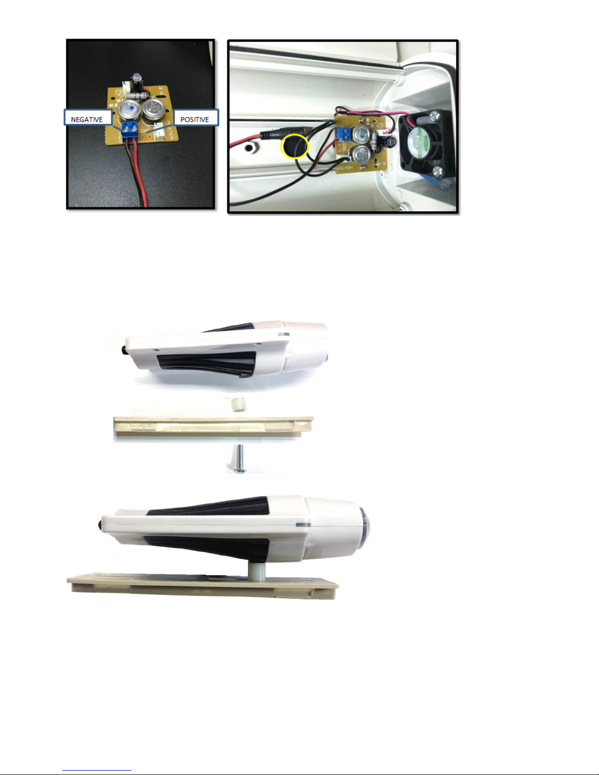
Step 4: Connecting Control PCB
Strip 3/16” of the insulation from the heater unit power cable and attach it to the control PCB, as shown below.
Once the cables are secured, install PCB board back in place and feed the cable through the provided hole in the middle.
Page 25
Copyright 2017 VIAAS, Inc.
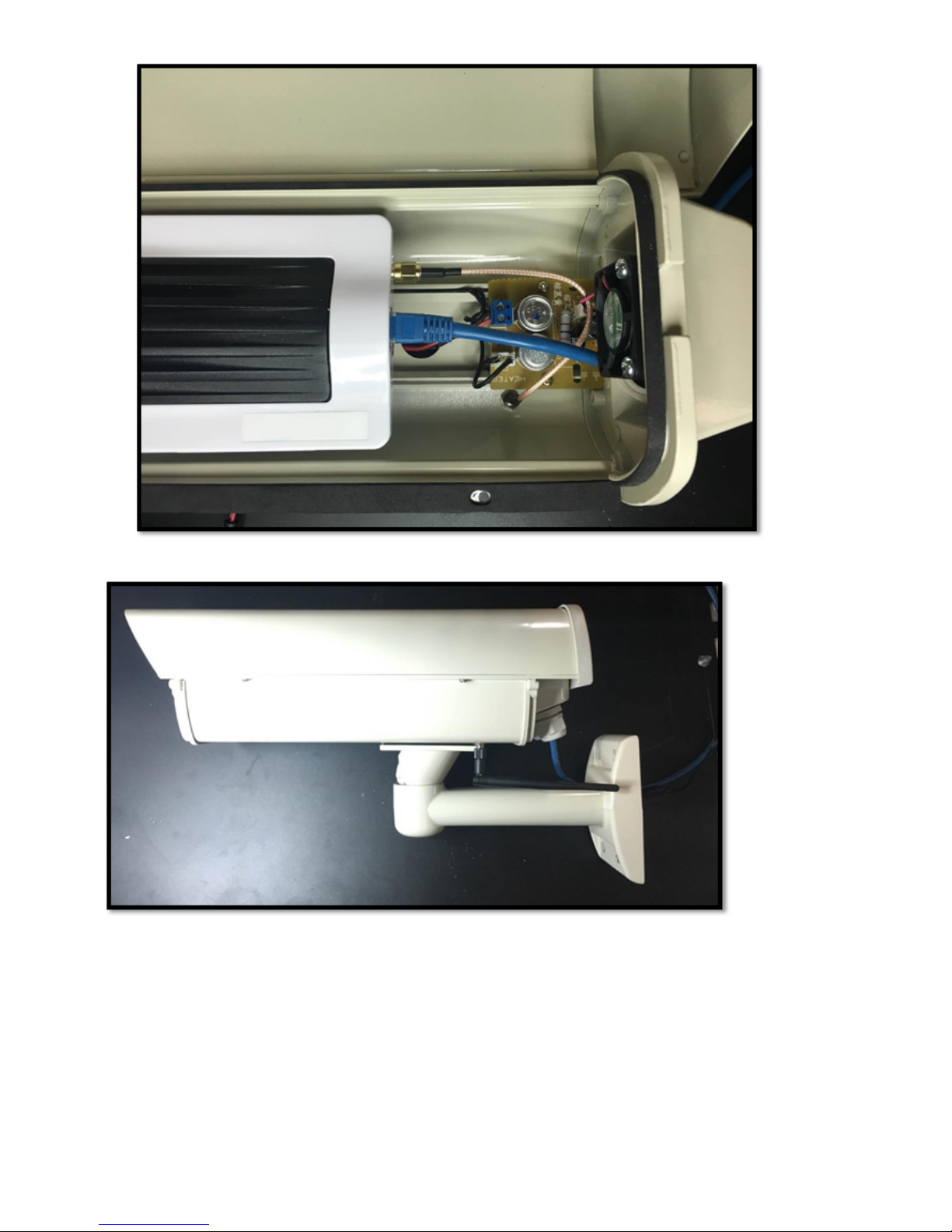
Step 5: Mount Camera to Camera Mount
Using the ½" spacer and the 1" ¼-20 screw, mount the camera to the camera mount.
Fit the camera inside of the enclosure. Adjust the camera back and forth so the lens is ¼ - ½" back from the glass.
If the lens is too close, the zoom mechanism will hit the glass. If the lens is too far, the wide angle of the lens will see the edges of the enclosure.
Once you know where to position the camera, tighten the screw, remove the lens cover, then click the camera and its mount into the enclosure.
Step 6: Secure Camera Mount and Control PCB
Secure the camera mount and control PCB, as shown here.
Page 26

Copyright 2017 VIAAS, Inc.
1.
2.
Step 7: Final Cable Connections
Terminate Ethernet cable with an RJ-45, and connect that to the camera.
Pass the stripped cable through either one of the conduits located on the back side of the camera.
Step 8: Mount Assembly
Supplied Mount Accessory Items
Page 27

Copyright 2017 VIAAS, Inc.
1.
2.
3.
Turn the enclosure over. Align the holes on the underside of the enclosure with the holes in the spacer, as shown below.
Continue feeding the control PCB power cable all the way through the arm mount.
Secure the arm in place, using the provided screws and hex key, as shown below.
Page 28

Copyright 2017 VIAAS, Inc.
The completed mount should look like this:
Page 29

Copyright 2017 VIAAS, Inc.
1.
2.
Step 9: Wi-Fi Antenna Installation (Optional - Wi-Fi only)
Note: This section is optional. Use only when installing a Wi-Fi antenna.
Open the enclosure.
Drill a 1/4" hole on either side of the enclosure. Remove all burrs and cuttings.
Page 30

Copyright 2017 VIAAS, Inc.
3.
4.
Using the supplied lock washer and nut, install the RP-SMA extension cable into this hole.
Connect the RP-SMA cable to the camera and connect the Ethernet cable to the camera, as shown below.
Page 31
Copyright 2017 VIAAS, Inc.
The completed antenna installation should look like this:
If you are configuring the camera for wireless, configure and test the wireless settings using a wired connection on the ground. Refer to VIAAS
Camera Installation Tips for details on setting up Wi-Fi.
Step 11: Replace the Enclosure Lid
If you removed the enclosure lid earlier, replace it now.
Part II: AT THE INSTALLATION SITE
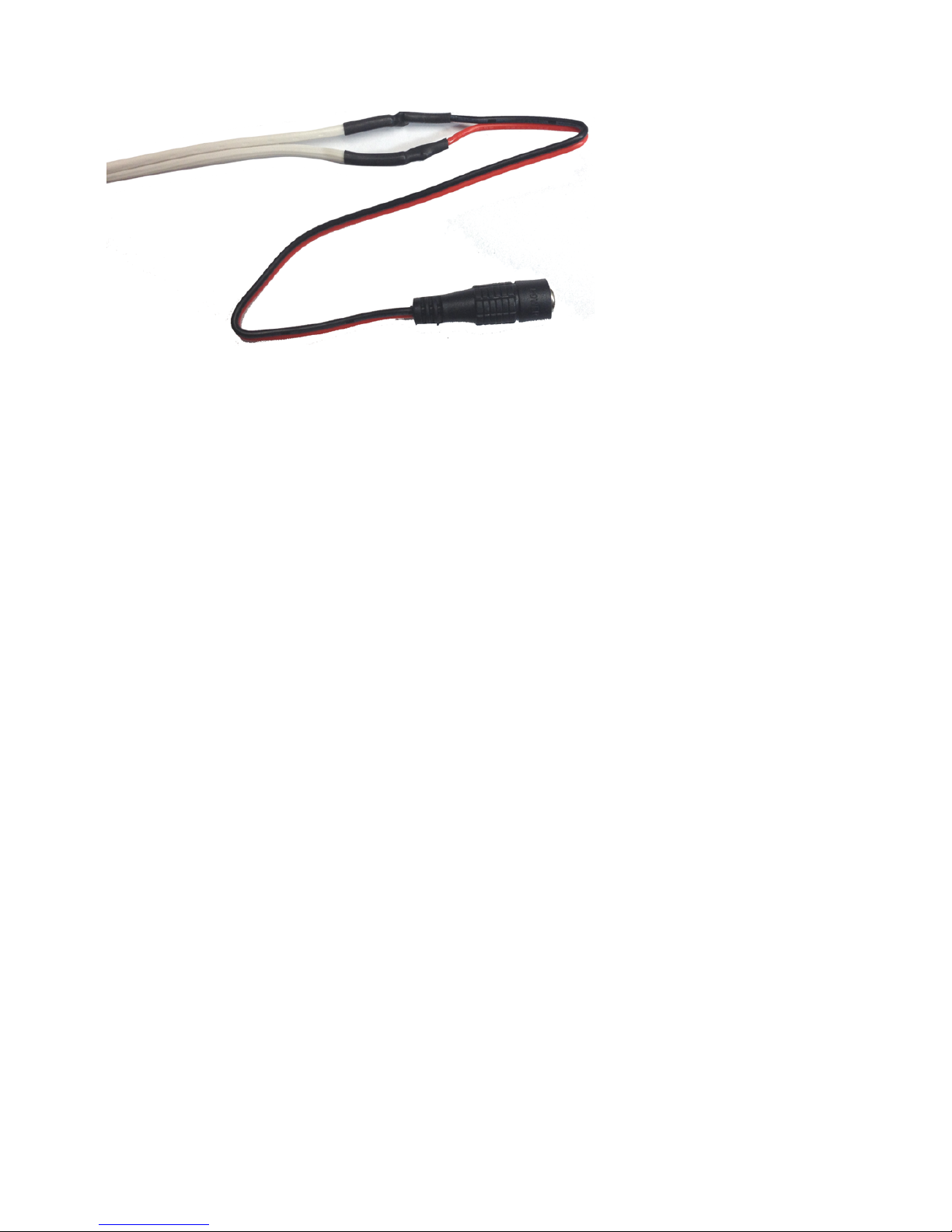
Connecting the Power Adaptor
The power adapter for the heater is not outdoor rated. It must be installed in a protected location.
Page 32
Copyright 2017 VIAAS, Inc.
1.
2.
Connect the female plug supplied with the power adapter to the wire that runs to the control PCB using solder and heat shrink tubing.
Once everything is ready, connect the cable to the power adapter and plug in the adapter.
Note that the control PCB provides no indication of proper operation. The heater should turn on when the temperature is below 0°C (32°F). The
Short of heating or cooling the assembly, the installer can check at least tofan should turn on when the temperature exceeds 48°C (118°F).
assure that 24 VAC is present at the screws on the terminal block where the power connects to the control PCB.
The unit is now ready to be installed in the location you have chosen.
Page 33

Copyright 2017 VIAAS, Inc.
Understanding Locations, Groups, and Roles
Before you begin working with VIAAS, it is helpful to understand how cameras and users are organized and managed.
Read the following articles to familiarize yourself with the Locations, Groups, and Roles.
Understanding Locations
Understanding Permissions and Roles
Understanding Camera Groups
Page 34
Copyright 2017 VIAAS, Inc.
Understanding Locations
You must assign a location to each new device you add to the system. This streamlines the process of configuring cameras and assigning
permissions. Using the location, Superusers can control permissions, notifications, and bandwidth schedules across multiple cameras at once.
How you choose to define locations might depend on the size and geography of your organization and how you are using VIAAS. If you have an
organization in multiple sites, you might choose to create locations based on geography – by city (e.g., London, New York) or, if in the same city,
by address (e.g., Elm St., Main St.). If you have a small organization in one site, you might choose to have a single location for all of the
cameras, or you might choose to have locations for multiple cameras located on different floors (e.g., floor1, floor2) or by department (e.g., sales,
shipping/receiving). Your location assignments might also be influenced by network topology, because future system enhancements will allow
you to assign bandwidth limits to a location, thereby allowing the VIAAS servers to dynamically allocate that bandwidth to cameras based on
need.
Note that individuals who do not have access to cameras within a location will not see that entry in the Locations list. For example, if a user has
access only to "Boston" cameras, they will only see the "Boston" location and not any other locations in the Locations list.
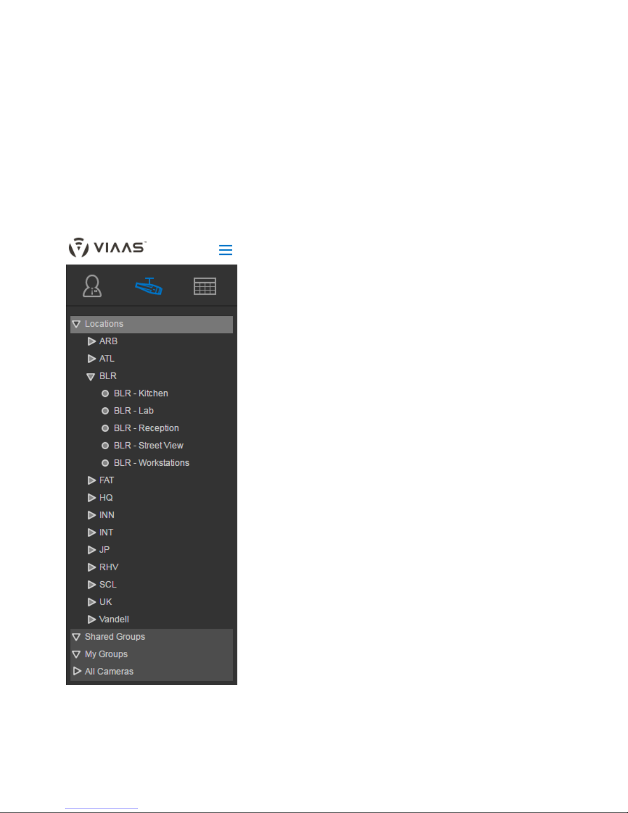
The image below shows locations for cities where offices are located, using codes based on airport codes.
Superusers are the only individuals who are able to work with locations, defining them and configuring them.
For details on groups, refer to Understanding Camera Groups.
For information on working with locations, refer to How to Manage Locations.
Page 35

Copyright 2017 VIAAS, Inc.
Existing VIAAS Users
If you were already using VIAAS before the Locations feature was introduced, your cameras will continue to function as they always have.
With this release, your cameras are all assigned to a default location. This will not affect your cameras or anything else in your system. It is your
choice if you want to make any adjustments.
If you choose to rename the default location name or add more locations, refer to How to Manage Locations.
Page 36
Copyright 2017 VIAAS, Inc.
Understanding Permissions and Roles
This article provides conceptual information on permissions and roles. For information on managing them, refer to How to Manage Users and
.Roles
For information on location, refer to .Understanding Locations
Permissions
You grant permissions to users to give them the ability to see or modify a camera.
A user can have the following permissions:
Admin – can view the camera live as well as review motion timeline and recorded motion video clips; can configure camera settings
User – can view the camera live as well as review motion timeline and recorded motion video clips
None – cannot view the camera at all.
Setting by Individual Camera and by Location
You can set permissions for one or many cameras in the Edit User dialog. An individual can be a user on all cameras, but an admin on just a few,
or they might have the "None" permission for all cameras.
You can also set these permissions by camera location. If you set an individual to have user permission on all cameras at the HQ location, then
whenever a new camera is added to the HQ location, that individual will automatically have user permission on it.
If you set permissions by individual cameras, when a new camera is added to a location, you must manually update each individual's permission
for that camera. Using roles can eliminate the chore of manual entry. Continue reading for information on using roles.
Roles
Roles are a way of grouping users logically, to streamline the process of assigning permissions.
The Superuser role is the only role that is predefined with VIAAS. Users who have the Superuser role can control anything in the system. You can
create additional roles that help you manage user permissions in your organization. For example, you might consider creating the following types
of roles:
Admin All – can view and administer all cameras in all locations. Useful for employees with administrative duties across geographies.
HQ Admins – can view and administer all cameras at the headquarters location. Useful for administrators at the HQ location.
HQ users – can view all cameras at the headquarters location. Useful for security employees at the HQ location.
HQ lobby – can view only lobby cameras at the headquarters location. Useful for reception desk and lobby security employees at the
HQ location.
Roles and Locations
Note that when you define a role:
where users have permission for , whenever a new camera is added to the location, the user willall cameras within one or more locations
automatically have access to that new camera. This describes the first three roles listed above.
where users have permission for in one or more locations, when a new camera is added, the user will notonly certain cameras
automatically have access to it. In this case, the administrator edits the role and adds permission for that camera. This is easier than
adding permission for each user individually. This describes the last role listed above.
Some important points about roles:
Users can only have one role.
You assign a role to a user when you edit the user.
Editing a affects all users with that role.
Deleting a role requires that there are no users associated with the role.
can view the camera live as well as review motion timeline and recorded motion video clips
Page 37

Copyright 2017 VIAAS, Inc.
Understanding Camera Groups
You can create groups for cameras, so they are easier to view. On a camera view, you can select a group of cameras
Locations are a special kind of group. For details on location, refer to and .Understanding Locations How to Manage Locations
Shared Groups
Users with the Superuser role can create one or more Shared Groups. Shared Groups of cameras are intended to relate cameras in ways other
than location, such as specific location, type, and configuration settings. Shared Groups of cameras are visible only to individuals who have
permissions for the cameras within the Shared Group. If a user only has permissions for some of the cameras within a group, they will see the
group name with only the cameras they are allowed to see. If a user does not have permissions for any of the cameras, for security purposes,
they will not even see the name of the Shared Group.
My Groups
Users with the Superuser role can create one or more entries for My Groups. These groups cannot be shared with other users; they are for your
own individual use.
All Cameras
All Cameras is a group which contains all cameras in the system.
Roles
Roles are used to assign permissions to users for certain cameras. For details, refer to and Understanding Permissions and Roles How to
Manage Users and Roles
Page 38
Copyright 2017 VIAAS, Inc.
Administrative Functions
Administrative functions, with the exception of updating personal information, are available only to users with or Admin Superuser
role.
Configuring cameras is an administrative function performed on the in mode.Configuration Panel Cameras
To access administrative functions, click the Admin icon on the top of the left panel.
For information on how devices and users work together, refer to .Understanding Locations, Groups, and Roles
Accessing Help and Support
Click at the bottom of the side panel to access Help, Support, and FAQs. Help
Administrative functions include:
How to Manage Cameras
How to Manage Locations
How to Manage Users and Roles
How to Manage Camera Groups
Page 39
Copyright 2017 VIAAS, Inc.
1.
2.
3.
4.
1.
2.
3.
4.
How to Manage Cameras
Adding cameras is an administrative function.
This page describes how to add cameras. For information on configuring cameras, also an administrative function, refer to the Configuration
Panel article.
Adding Cameras
Only users with the Note: Superuser role can add a camera.
To add a camera to your account:
Click the Admin icon in the side menu to enter Administrative mode.
Click the Services icon at the top of the page.
Click . The window appears. Provide the following information:Add Device Add Device
Device Type – Select VIAAS or ONVIF Camera.
Device Serial Number – (VIAAS cameras only) Enter the serial number of the new camera, found on a sticker on the
camera – on the side for bullet cameras and inside the dome for dome cameras.
Device Name – Give the camera a name. Names must be 30 characters or fewer and can include underscores and dashes.
Device Location – Select a location from the list of locations you created or click New to add a new location.
Each camera must be associated with a location.
Device Timezone – Select the time zone where the camera is installed. The timezone setting on the camera controls
camera-based activities and sets the time stamp on videos.
Click to set up the camera.Continue
Click to leave this screen without performing the setup. Cancel
Viewing Service Information for Cameras
Click the Services icon to view a list of cameras.
Cameras are listed in alphabetical order, along with their MAC address, Serial Number, Retention Period for Video, Retention Period for
Preview, and Service Expiration.
For VIAAS cameras, the date in the Service Expiration column highlights as the time to renew the contract approaches.
For details on adjusting camera settings, refer to Configuration Panel.
Renaming Cameras
Superusers can rename cameras within the camera list in the left panel.
To rename a camera here:
Select one camera in the camera list in the left panel.
Click at the bottom of the pane.Rename
Type a new name for the camera.
Click somewhere else on the screen.
Page 40

Copyright 2017 VIAAS, Inc.
1.
2.
1.
2.
3.
4.
How to Manage Locations
For conceptual information on location, refer to .Understanding Locations
Specifying a New Location
When you first add a device to the system, you must specify its location.
You can specify a new location in either the camera or gateway configuration pages.
In the field, select .Device Location New
Type a new name, then click .Device Location OK
The new location is assigned to this device and is available to assign to other devices.
Location Settings
Location settings affect the cameras assigned to that location.
Note the following:
Timezone
The location timezone is used for location-related settings, like bandwidth schedules.
The camera timezone is used for camera-related settings and is the timezone associated with events recorded by the camera.
Email Alerts
There are two types of alerts:
Administrative Alerts – Set in settings – Required for setup. Alert the location-based administrator of potential issues, suchLocation
as a camera's going offline.
Motion Alerts – Set in settings Alert appropriate personnel to events like motion detected on a camera during scheduled alertCamera –
periods.
If you require multiple email addresses for an alert, separate the emails with commas.
Bandwidth Management
Location-based bandwidth is shared by all VIAAS 2.0 cameras at a single location. Administrators can now assign a block of bandwidth to all of
the cameras at a location, allowing the VIAAS system to allocate the bandwidth dynamically to each camera, based on factors like how the duty
cycle for each camera might change based on time of day and day of the week.
VIAAS cameras prior to version 2.0 manage their own bandwidth and are controlled individually.
Renaming Locations
Superusers can rename locations within the camera list in the left panel.
To rename a location:
Select one location in the camera list in the left panel.
Click at the bottom of the pane.Rename
Type a new name for the location.
Click somewhere else on the screen.
Page 41
Copyright 2017 VIAAS, Inc.
1.
2.
How to Manage Users and Roles
Managing Users and Roles is an administrative function.
Only users with the role can perform the functions described on this page.Superuser
To access administrative functions, click the Admin icon on the top of the left panel.
Click the Users icon to manage users.
Viewing Users and Roles
When you click the Users icon, you will see two lists:
Users – Displays names of all , along with the and number of for which the User has permission.Users Role Cameras
Roles – Displays names of all , along with the number of and .Roles Users Cameras for which the Role has permission
Each list is sorted alphabetically and enables you to edit the or directly from the list. Editing Users and Roles is described below.User Role
For a brand new account, only the user who created the account is listed.
Two Methods of Adding Users
Review for background information to help you best manage your users for your installation.Understanding Permissions and Roles
A. Add users individually – suggested for small installations with limited numbers of cameras and users.
B. Add roles – suggested for larger installations with many cameras and users, to which you will likely add more users.
Refer to the corresponding lettered sections below for information on each of these methods.
A. Adding Users Individually
To add a user, click at the top of the .Add New User Users List
In the dialog, specify basic information for the user:Add User
First and Last Names
Email (must be unique)
Password
Specify a for this user. Each user can only be associated with one role.Role
Superuser – Full permissions on all cameras. Can create and edit other users. There is no limit on the number of Superusers
you can have on your account; however, this role has full control of the system, so be highly selective when assigning it to users.
<Other Role> – Select a Role you defined in the section below.Adding a New Role
Custom – Select camera privileges for this user. You can add privileges by location or by individual camera. Use the fieldFilter
to help you search for cameras or locations.
In most cases, you will , to specify the same permissions for all cameras within aspecify permissions by location
location, including any cameras you add to the location in the future. To associate user permissions with a location,
select , , or in the same row as the location name.Admin User None
If you need a for a location, expand the location name, then select the permissions for eachmix of permissions
individual camera.
The available permissions are:
Admin – Users can perform administrative functions cameras and locations.
User – Users can only view the individual cameras and locations, and cannot make any adjustments to them.
None – Users cannot see the camera or location.
The image below shows how you can select one permission for all cameras within a location (see the blue box around the ATL location
and all locations after FAT), or a mix of permissions for cameras within a location (see red box around the BLR location).
Page 42

3.
1.
2.
3.
4.
1.
Copyright 2017 VIAAS, Inc.
Note that when multiple roles are selected for different cameras within a single location, the role selectors at the top of the location are
light gray, and display the various roles that are selected below. For example, the role for the BLR location in the image below has both
User and None privileges, so both the User and None indicators at the BLR top level are light gray. The role for the ARB location in the
same image must have a combination of Admin and None privileges, given the coloring of the indicators at the ARB level. The role for
other locations in the image below all show the None privilege, since the None indicators are all dark gray.
Click to save the settings for the new User.Save
B. Adding a New Role
If you will have multiple users with the same permissions, it is helpful to define those permissions as a Role, then assign the Role to the users
when you add the users.
To add a new Role:
Click Add New Role.
In the Add Role dialog, specify a name for the Role.
Specify the permissions for the role, either by location or by individual cameras in each location.
This process is the same as that described above for Users.
Click Save to save your changes.
Editing Users and Roles
Editing a User
To edit an existing user:
Locate that user in the .Users List
Page 43

Copyright 2017 VIAAS, Inc.
2.
3.
1.
2.
3.
1.
2.
3.
4.
1.
2.
3.
4.
5.
Click in the row of the user you want to edit.Edit User
Make changes to the values described in the section above.Adding a User
Editing or Renaming a Role
To edit an existing role:
Locate that role in the .Roles List
Click in the row of the role you want to edit.Edit Role
Change the name of the role or change permissions, as described in the section above.Adding a New Role
Changes you make to the role will allfect all users assigned to that role.
Deleting Users and Roles
Deleting a User
To delete an existing user:
Locate that user in the .Users List
Click in the row of the user you want to delete.Edit User
In the dialog, click .Edit User Delete User
Confirm that you really want to delete the user.
Deleting a Role
Note: You can only delete a role if there are no users assigned to it.
To delete an existing role:
Locate that user in the .Roles List
Ensure that there are no users associated with that role.
Click in the row of the user you want to delete.Edit Role
In the dialog, click .Edit Role Delete Role
Confirm that you really want to delete the role.
Page 44

Copyright 2017 VIAAS, Inc.
1.
2.
3.
4.
5.
6.
1.
2.
3.
4.
1.
2.
How to Manage Camera Groups
For background information on camera groups, refer to .Understanding Locations, Groups, and Roles
Creating a New Camera Group
In the camera list in the left panel, click one of the following:
Shared Groups – to create a group that can be seen by all users with permissions for the cameras in the group
My Group – to create a group that only you can see and use
At the bottom of the camera list, click .New
Type a name for the group, then click elsewhere on the screen.
Click the name of the group you just created and click .Edit Group
Select the cameras you want to include in the group. Use the filter field to help you find cameras.
Click .Save
Editing a Camera Group
In the camera list in the left panel, click the name of the group.
Click .Edit Group
Select the cameras you want to include in or remove from the group. Use the filter field to help you find cameras.
Click .Save
Deleting a Camera Group
In the camera list in the left panel, click the name of the group.
Click .Delete
Only users with the Superuser role can create and manage groups.
Page 45

Copyright 2017 VIAAS, Inc.
Camera Functions
Camera functions enable you to view camera output in various ways.
Click a camera function panel to learn more about it.
Images Panel
NOW Panel
Timeline Panel
Configuration Panel
Available to Admin level users or higher.
Standard Features in Panels
Selecting One or More Cameras to View in Any Panel
For all camera functions, select one or more cameras from the left panel. Selected cameras show as light gray, against the dark gray
background.
To select an entire location or group, select that location or group name, with the arrow next to it.
To select a single camera, click the name of the camera with a circle next to it.
To deselect a camera, location, or group, click it again.
The following figure shows two single cameras selected in the ARB location and the entire ATL location of cameras selected.
Page 46

Copyright 2017 VIAAS, Inc.
Page 47

Copyright 2017 VIAAS, Inc.
1.
2.
Configuration Panel
Use the Configuration Panel to configure cameras in your account.
Best Practices for Camera Configuration
Configure individual cameras for their initial setup, including adjusting settings including focus, zoom, and enabling the preview stream.
As part of this configuration, specify the Location for the camera.
This step requires the Admin or Superuser role for the specific camera.
After the initial setup, control shared configurations by updating settings for the Location.
This step requires the Superuser role.
Refer to these articles for camera configuration:
How to Configure a Single Camera
How to Configure Multiple Cameras
Page 48
Copyright 2017 VIAAS, Inc.
1.
2.
3.
1.
2.
1.
How to Configure a Single Camera
There are two ways to open the Configuration window.
In Camera mode, click the Configuration Panel icon .
Select one or more cameras in the side panel. You can view the configuration for all cameras in a list, sorted alphabetically by camera
name.
Click the Settings icon associated with the camera you want to configure.
OR
In Camera mode, select either the NOW Panel or Timeline Panel.
In a camera viewer, click the Camera Settings icon in the upper left corner.
Configuring an Individual Camera
With the Configuration window open, you can configure the camera.
In the Configuration window, specify the following configuration elements. These elements differ for different cameras. This list includes
settings from all camera types. You will likely not have of these settings in your configuration.all
Camera Name – Type a name for the camera. Cameras are sorted alphabetically by name. To keep related cameras grouped
together on a screen, develop a naming system that incorporates numbers or similar initials for cameras within a certain facility
or area.
Time Zone – Select the time zone where the camera is located. Alert schedules and bandwidth schedules operate on camera
time.
LED Enable – Cameras have LED lights that can be set to blink every few seconds. Select to draw attention to theLED Enable
camera or leave it blank to keep the camera somewhat hidden.
Audio Enable – Select to capture audio along with the video capture. If this option is not active, the camera is not equipped with
a microphone.
Preview Stream Enabled – Select to have the camera send preview images for active monitoring.
Preview Stream Rate – Select the time interval between Preview Images, ranging from 1-32 seconds depending on your
service plan. A smaller setting delivers more preview images and requires more bandwidth.
Video Resolution – Select the video resolution, either 720*480 or 1280*720.
Camera Orientation Flip – For cameras mounted on the ceiling, you might need to flip the image so it has the proper
orientation.
Camera Zoom/Focus – Click to open a new window where you can manually adjust the zoom and focus for theZoom/Focus
selected camera or to have adjustments made automatically. Click when you complete theSwitch to Auto Mode Done
adjustments.
Create Zones – Click Create Zones to open a new window where you can define areas where motion will trigger the camera to
record. For example, if your camera is pointed at a room where there is a window with traffic passing by, you might choose to
draw a zone that does not include the window, so cars going by will not trigger the camera to record. Specific instructions on
creating zones appears on the screen when you click Create Zones.
Motion Sensitivity – Adjust the slider to be more or less sensitive to the motion that will trigger recording events. More
sensitivity triggers more recording. (Some cameras show this as a percentage, instead of a slider.)
Bandwidth Shaping – Select this check box to enable Bandwidth Shaping. Bandwidth shaping averages out the data upload
over a longer period of time. Images are stored on the microSD card and trickled to the service without impacting your network.
Bandwidth – The default bandwidth for the camera, in kilobits per second, when there is no schedule.
Max Bandwidth – When no schedule is in effect and the microSD card is getting close to full, the camera will increase its
bandwidth to this setting. A value of 0 means there is no limit. If you do not set this value to either 0 or a number greater than
500, the microSD card might become full and the camera will begin to overwrite the oldest video on the card.
Free Storage – Amount of storage capacity, in MB, remaining on the microSD card that triggers , describedMax Bandwidth
directly above. For example: A setting of would trigger when the microSD card is within 1000 MB (1 GB)1000 Max Bandwidth
of being full.
Bandwidth Schedules – Click the green to set one or more schedules to control the camera bandwidth usage on specific+
days and times. For example, you can set the bandwidth lower during high-traffic times on your network and increase it at night
to allow the cameras to empty their microSD cards. Click the red to delete a schedule.X
Send Motion Alerts to – Enter an email address where alerts should be sent if motion is detected during an alert period.
Motion Schedules – Click the green plus sign to set one or more time periods when motion will trigger an alert to be sent.
Network Connection – Select how the camera will obtain an IP address, either or .Ethernet DHCP Static
Ports – Specify one or more ports the camera can use to connect to the service.
Interface Preference – Select your preference for this camera: ; ; Use Ethernet, Disable Wifi Use Ethernet, Wifi Backup Use
Wifi, Ethernet Backup
Configure Wireless – Click to configure and test wireless settings on the camera. Click when youConfigure Wireless Done
have finished.
Page 49
Copyright 2017 VIAAS, Inc.
2. To apply your preferences and continue working in the Configuration window, click . When you have finished, click .Apply Save & Exit
Please Be Patient
Please be patient when configuring a camera, allowing one to two minutes for a change to take effect. Any change you make first goes
to the cloud, then to the camera, which must then adjust to that change.
Page 50
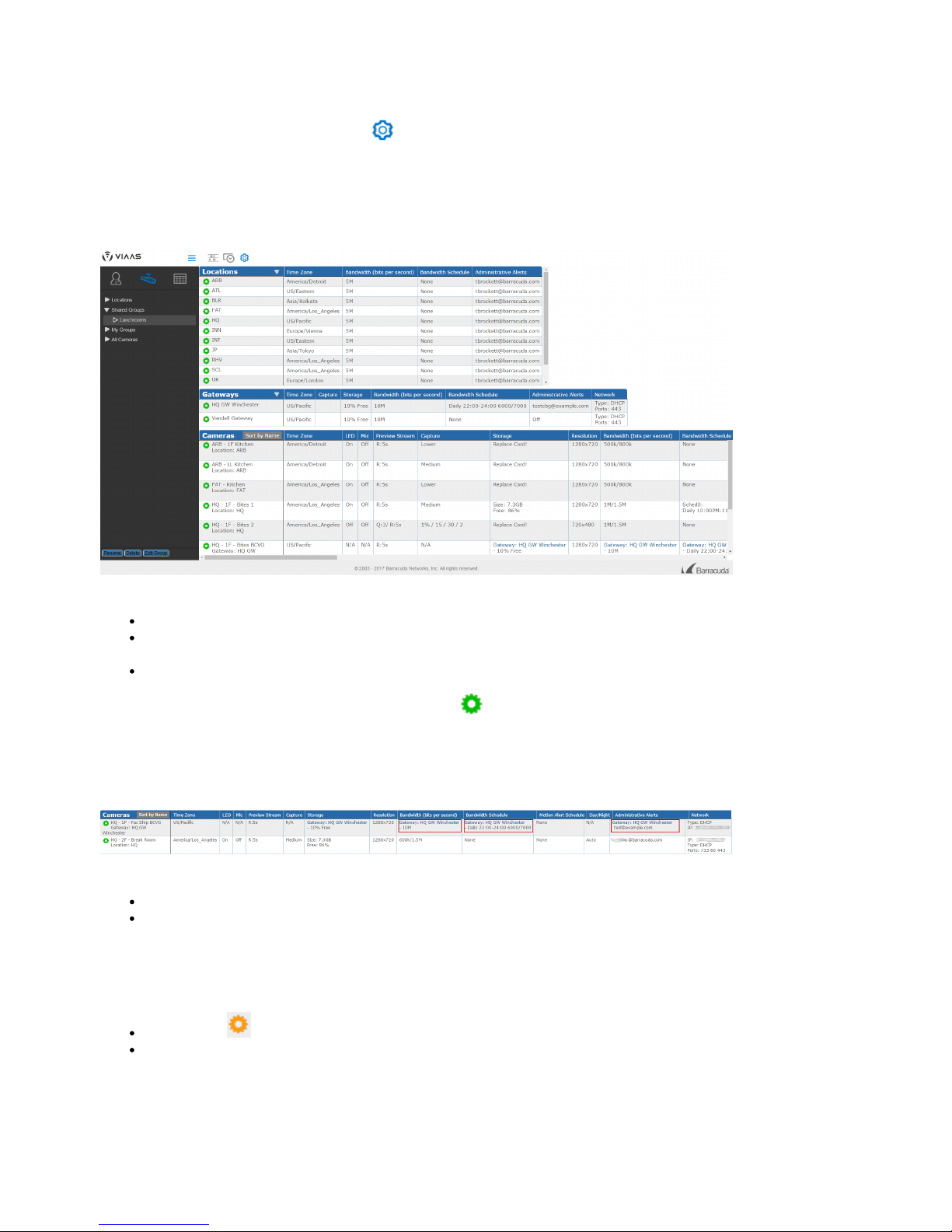
Copyright 2017 VIAAS, Inc.
How to Configure Multiple Cameras
Opening the Configuration Panel
In Camera mode, click the Configuration Panel icon to display the Configuration Panel.
Use the camera list in the left panel to choose which cameras to display.
You can only see cameras for which you have Admin or Superuser permissions, this includes cameras in Shared Groups.
Shared Group names created by a Superuser. Here, the Shared Group name is Lunchrooms. Refer to Understanding Camera Groups for more
information on Shared Groups.
The Configuration Panel displays basic information for the items selected in the left panel:
locations
gateways – A gateway only displays if you have a gateway on your system and if you have selected a camera on that gateway in the left
panel.
cameras
You can view this information at a glance or click a configuration icon to configure one of these items.
You can configure individual cameras, or configure a location or gateway to affect the cameras it contains. If a camera has settings from a
gateway or location, the inherited setting is shown in the Camera table at the bottom of the screen. The image below shows that the Fac Ship
camera is associated with a HQ GW Winchester gateway and has inherited settings from the gateway for Storage, Bandwidth, and Bandwidth
Schedule.
Refer to the following articles for more details:
How to Configure a Single Camera
Understanding Locations, Groups, and Roles
Alerts on this page include:
Camera Offline – The camera is not connected to the system. It might be powered off or there could be a connectivity issue.
Replace Card – The SD card is full or getting full. Make space on the card or replace it.
Page 51
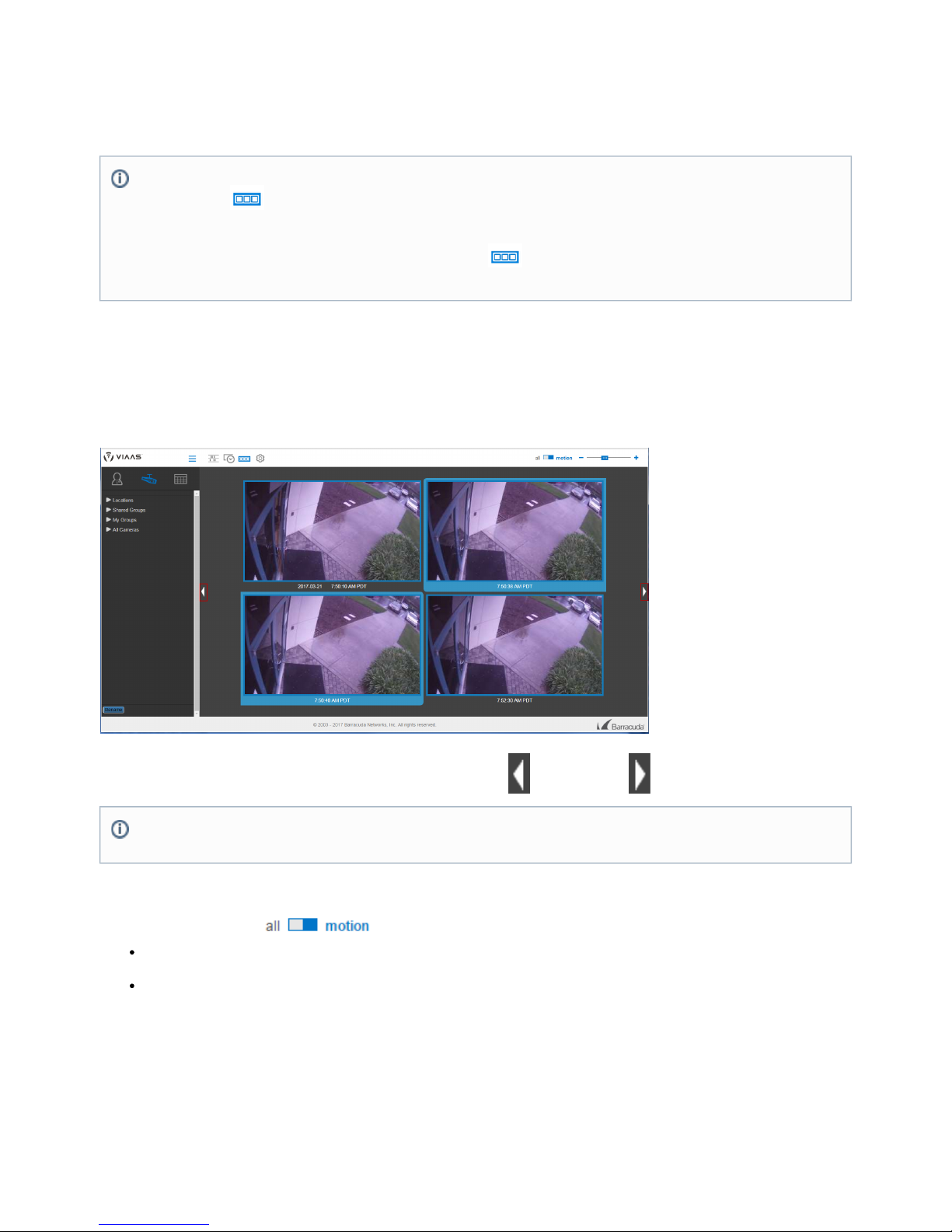
Copyright 2017 VIAAS, Inc.
Images Panel
The displays many images from one camera on a single screen. Use the Images Panel to look through motion thumbnails for aImages Panel
specific event or to review all for something that did not trigger motion detection.Preview Images
Actions within the Images Panel
Navigating the Images Panel
The time an image was captured is displayed under each image. The first image in the panel always shows the date. The first image after
midnight shows the date, regardless of where it appears on the page.
Use the large arrow buttons on each side of the page to navigate back in time or forward in time through the images.
Selecting Images to Display
Use the to control the types of thumbnail images displayed:Image Type Selector
motion – Only images captured by motion detection software.
Motion images have a colored highlight around their frames.
all – All images, including motion and preview images.
Preview images do not have a colored highlight around their frames.
For details on Motion and Preview Images, refer to .NOW Panel
Playing Clips from the Images Panel
When you hover your mouse over a motion thumbnail image, the highlight becomes larger, indicating that it is part of a video. If several
contiguous frames highlight, the motion event spans those frames. Most motion events also include some preview images, visible if you select all
images, as described above.
When a motion event includes multiple images, the highlight around the frames has rounded corners to show the first and last images of the
The Images Panel displays images at the top of the page from only a single camera.
The Images icon appears only when a single camera is selected. You must deselect all but one camera for the icon to be
visible.
You can also access the Images Panel by clicking the Images icon in the bottom right corner of the camera view in the NOW
or the .Panel Timeline Panel
The position in time in the Images Panel is shared with the Timeline Panel. To move hours or days quickly, go to the ,Timeline Panel
select the desired date and time, then return to the Images Panel.
Page 52
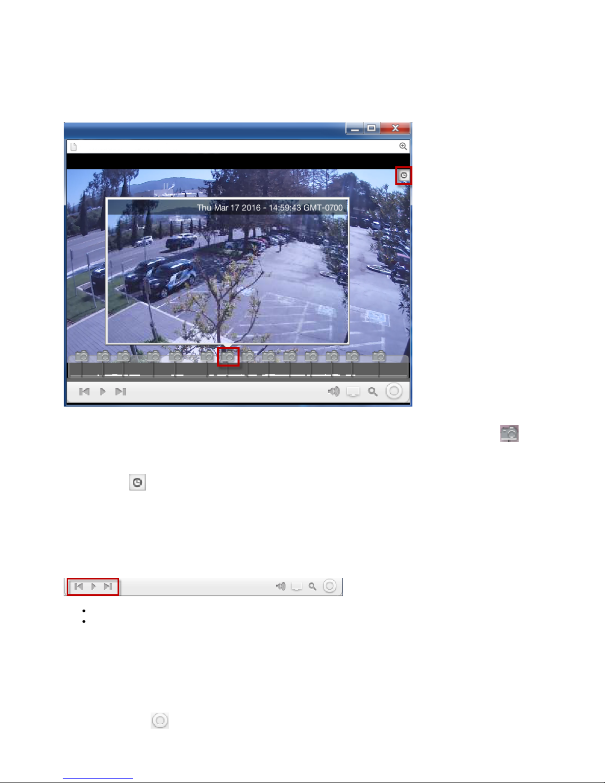
Copyright 2017 VIAAS, Inc.
motion event. If the event continues on the next line or the next page, you will see square corners on the last visible image.
Click any image associated with an event to view the video for the entire event in a new window containing the video Player, described below.
Using the Player
When you play a video using VIAAS, a new browser window appears, running the Player. The Player can be resized and can be moved
around on your screen. The system remembers the last size and position, and uses that information the next time you play a video.
As the video is loading, a red progress bar indicates loading status. When you hover your mouse over the frame, the progress bar changes to a
motion graph with thumbnail icons. The graph indicates the amount of motion in the scene at each point in time. The thumbnail icons indica
te the relative positions of the motion thumbnail images. Hover your mouse over a thumbnail icon to display that thumbnail image within the
Player window. Click a thumbnail to display the associated higher resolution snapshot image in a separate browser window.
Click the clock icon in the upper right corner of the Player to view the timestamps associated with the video while it is playing. Click the
clock icon again to hide the timestamps. VIAAS remembers your clock preference for the next video.
Navigation in the Player
In the lower left corner of the Player, click the play/pause button to pause or continue viewing the video.
On either side of the play/pause button, there are buttons pointing to the previous and next motion event. Use these buttons to move forward and
back in time.
Hover over a button to view the thumbnail image for the associated event.
Click a button to play the event.
Moving through these events does not change the location of the playhead in the .Timeline Panel
When looking for a specific incident, you can navigate to the Timeline Panel to quickly move through time, and put the playhead position near
where you think the incident occurred. Then navigate to the Images Panel and start playing clips forward within the Player. If you decide that you
need to search backward, close the Player. Note that the playhead position remains on the point where you started.
Player Tools Menu
Hover over the menu icon in the lower right corner of the Player to display the menu, which includes:
Page 53

Copyright 2017 VIAAS, Inc.
Settings – Opens the settings for that camera, does not close the Player.
Filters – Allows you to adjust the picture to help see details in videos taken in less than optimal conditions (e.g., low light, back light). For
example, adjusting the gamma can improve your ability to see into shadows. Click Save to remember these settings on a
camera-by-camera basis, so you can optimize the playback of all of your videos.
Filters include: Saturation, Brightness, Hue, Gamma, and Sharpen.
Show/Hide Motion – Superimposes red boxes over the images that show where the camera detected motion, on a frame-by-frame
basis. This can help you find small motions in certain videos. It can also help you understand the camera's motion detection and allow
you to adjust the camera for optimum accuracy.
Add Event – Saves the currently playing clip/span as an Event. All video and still images recorded by the camera are stored on VIAAS
servers only as long as your service plan covers, typically 30 days. To access an event after that time period, save it as an event so it is
not deleted. Refer to Saved Events Functions for details on Events.
Download – Downloads video and still images from the currently playing clip or span. The video is converted to an MP4 on your local
computer, where you can email it, record it to CD, post it to YouTube, etc. Download options include:
Current Frame Image Downloads a copy of what you currently see in the video player –
Entire Video Clip Downloads an MP4 of the entire event –
Hi-Res Snapshot ither shows the current snapshot and allows you to download it, or picks one for display, and then you can – E
download it. You can also download a snapshot by clicking on the camera icon to view it, which provides you a download button.
Note: If you try to download a live video stream (from GO LIVE or clicking on a very recent event in NOW mode where you see a series of
tick marks at the bottom of the motion bar), the download will be done as the video is generated and may take up to five minutes to
complete. It is usually better to wait for the video to finish, and then download.
Digital Zoom
Click the icon in the lower right of the Player window to digitally zoom into a section of an image.Magnifier
When you click the magnifying glass, a Magnifier window opens within the Player window.
Click anywhere on the to move it around within the frame. Magnifier
Use the slider to zoom in on a point of interest within the frame. Zoom
Click the in the top right corner of the to close it.X Magnifier
Page 54
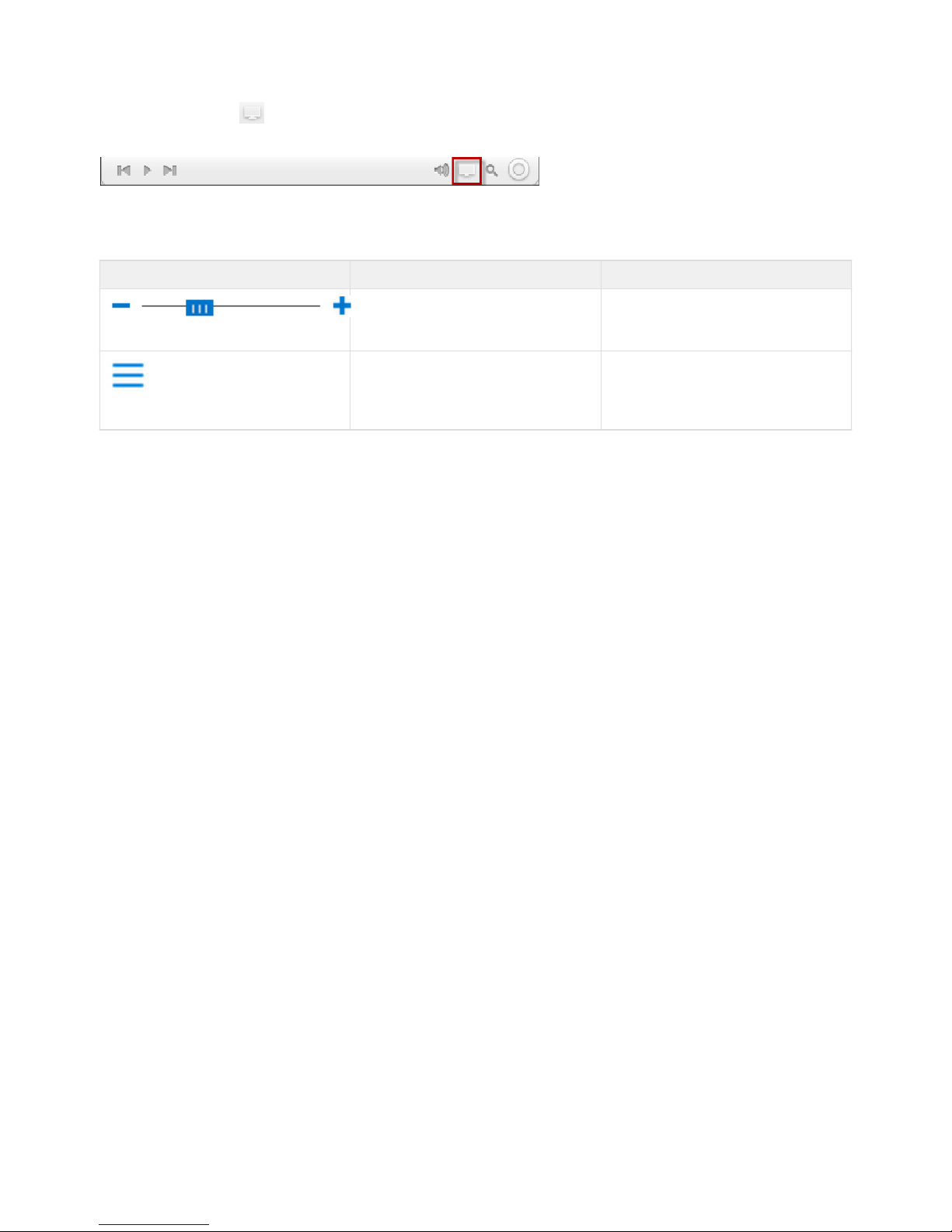
Copyright 2017 VIAAS, Inc.
Full Screen Mode
Click the icon in the lower right of the Player window to view video in full screen mode. Press on your keyboard to exit fullFull Screen ESC
screen mode.
Standard Features
Standard Features on the Images Panel include:
Tool Name Description
Image Size Tool Use the slider to make each camera image
larger or smaller. The smaller the image, the
more images you can fit on a single screen.
Show/Hide Side Panel Click this icon to show or hide the side panel.
If you do not need the navigation
functionality, hiding the side panel provides
more room to display camera images.
Page 55
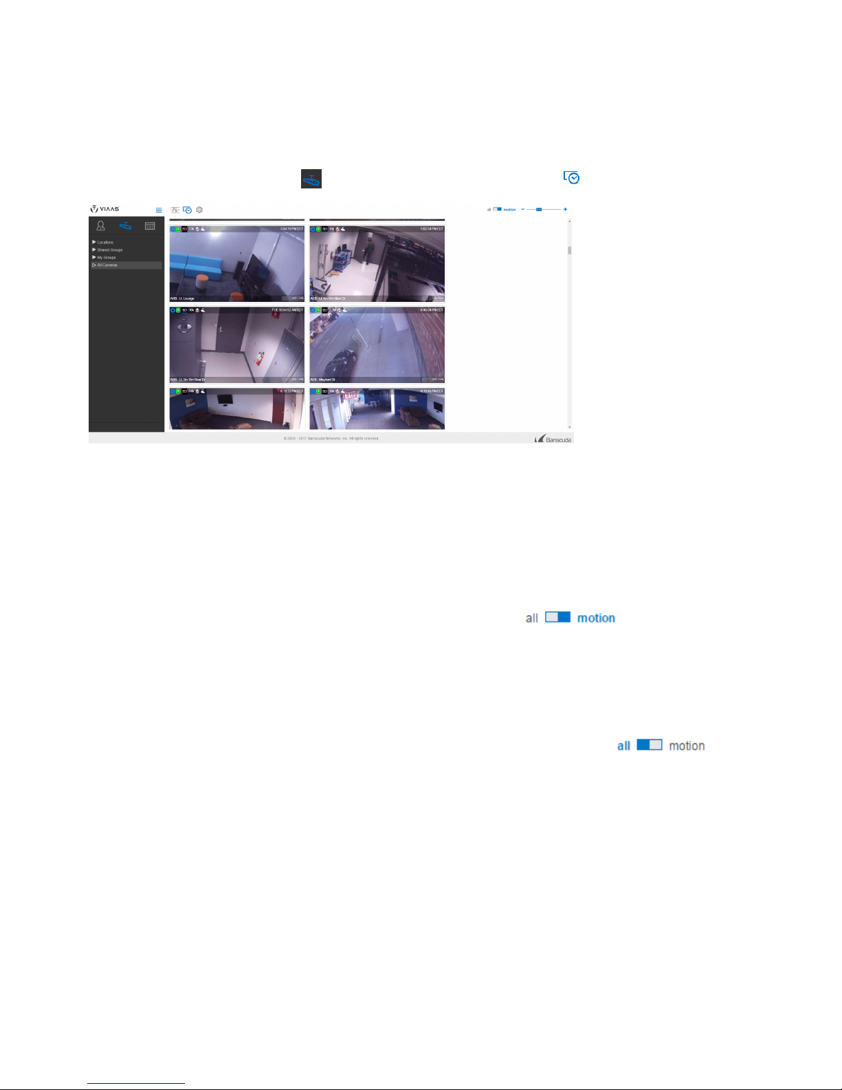
Copyright 2017 VIAAS, Inc.
NOW Panel
The displays current views for one or more cameras. Security or front desk staff can keep the NOW Panel on their screen to NOW Panel display
updated snapshots from multiple cameras at various locations. These Preview images allow near real-time monitoring at a fraction of the
bandwidth of streaming video. A snapshot of each camera view is displayed and will refresh every 1-32 seconds, based on your service plan and
camera settings.
To display the NOW Panel, click the Cameras icon in the side bar, then click the icon NOW Panel .
The NOW Panel displays the most recent still images for one or more cameras.
Images
Motion Images
VIAAS cameras have a motion detection feature that is always active. When motion is detected, the camera begins recording video and displays
a motion image. Motion images represent each recorded segment, for example, a person walking through a lobby, or a car entering a parking
lot. In the NOW Panel, the camera viewer border briefly highlights as a new motion image arrives, to draw attention to that camera. Motio n
images also help you find specific events in the Timeline Panel.
To display only motion images in the NOW Panel, select motion at the top right of the screen:
Preview Images
When there is no motion, such as a swimming pool that is closed for the evening, and the camera is set to send only motion images and/or the
NOW Panel is set to display only motion images, the displayed image is the last motion image captured as the pool closed. Over time, that image
does not change unless motion is detected. If you prefer to see a current image, an administrator can set the camera to send evpreview images
ery 1-32 seconds, depending on your service plan and camera settings.
To display all images NOW Panel both preview and motion images, select at the top right of the screen: in the , all
For example, if a camera is set to send a preview every two seconds and you selected in the all NOW Panel, the image from that camera is
always less than two seconds old. If the camera detects motion and begins recording, the motion image from that camera immediately displays
and the image border highlights to draw attention to it.
Camera Viewer Details
Each camera viewer in the NOW Panel includes multiple controls you can use when viewing the camera assets, monitoring camera status, and
managing the camera.
Page 56
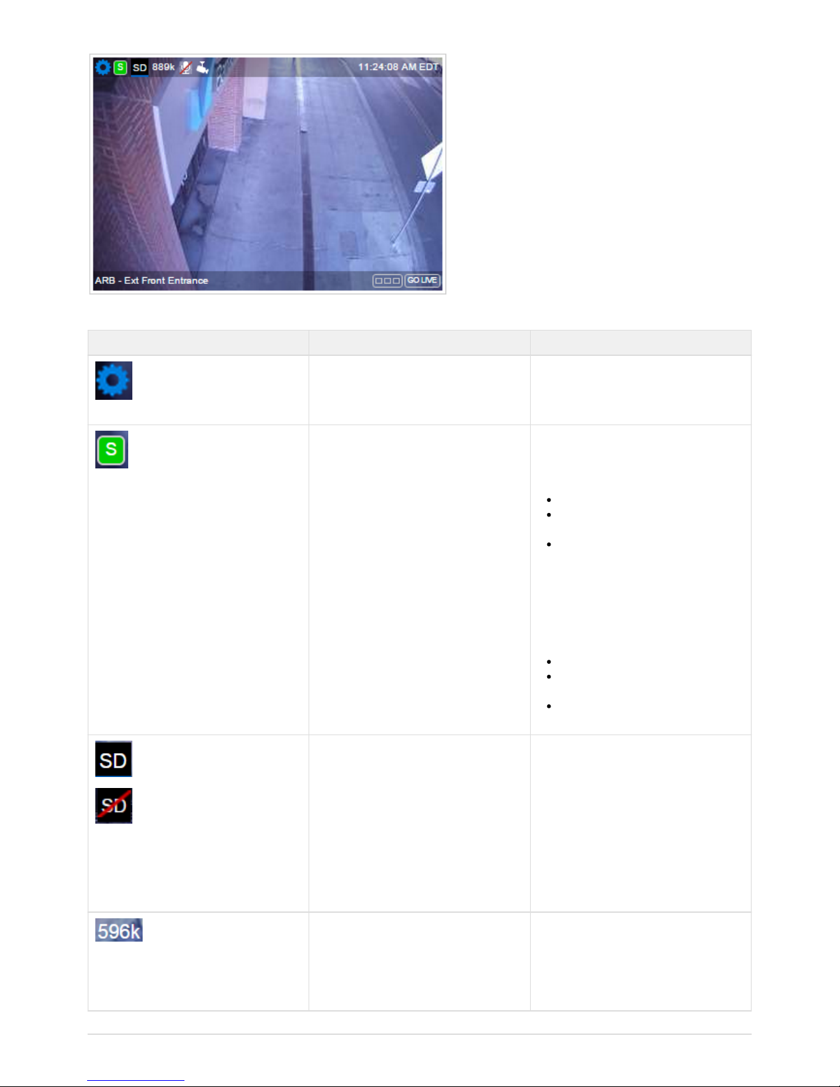
Copyright 2017 VIAAS, Inc.
The following table shows tools that appear in the camera image above. Some tools are shown in alternate forms, for illustration.
Tool Name Description
Camera Settings Shortcut to the camera configuration page,
where, with appropriate permissions, you
can review and change settings for the
camera.
Camera Status Current camera status, indicated through
color.
Colors include:
Green – normal operation
Orange – camera is offline, power or
Internet connection failure
Black – camera intentionally turned off
(see Camera icon below)
Click the status icon to open a status panel
for the camera.
The camera viewer displays color in the
lower margin to draw attention to any issues.
Gray – normal operation
Orange – camera is offline, power or
Internet connection failure
Black – camera intentionally turned off
(see Camera icon below)
SD Card Status Indicates whether the camera has an SD
card installed and its status. Hover over the
icon to see the percentage of the SD card
used.
When an SD card is nearly full, the SD icon
turns orange as a warning.
If your SD card is full, you can adjust the
bandwidth schedules to allow the SD card to
empty. Refer to onBandwidth Schedules
the for details.Configuration Panel
Current Bandwidth Usage Recent average bandwidth usage for the
camera, in kilobits per second (kbps). Under
normal conditions, it is less than the currently
scheduled bandwidth. A much higher
number indicates a full or missing SD card or
heavy live streaming use.
Page 57
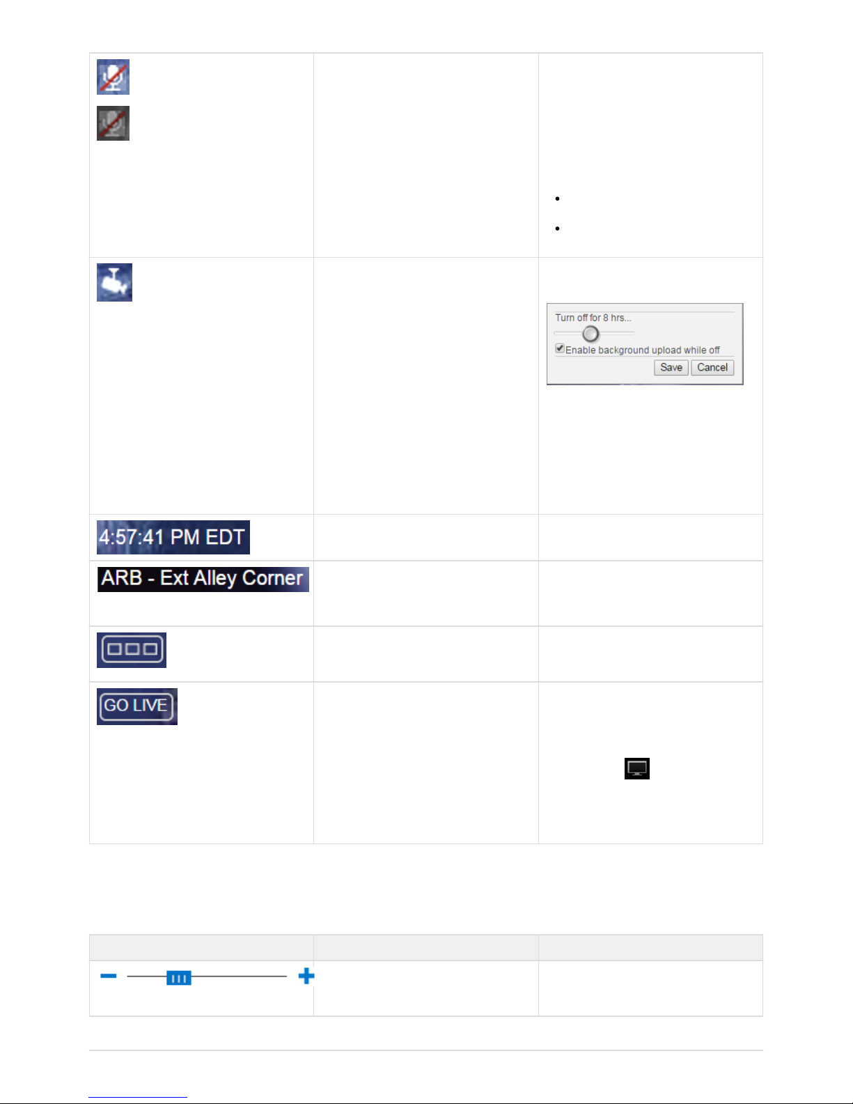
Copyright 2017 VIAAS, Inc.
Microphone Indicates whether the microphone on a
camera is on, for cameras capable of
recording audio.
Click the Microphone icon to change the
microphone state.
The color of the Microphone icon indicates
whether the microphone can be turned on:
white (upper image at left) – microphone
can be turned on
gray (lower image at left) – microphone
cannot be turned on
Camera Click the Camera icon to open a control
panel to turn the camera off.
In the control panel, use the slider to specify
how long to leave the camera off, from 30
minutes to indefinitely.
Select whether to enable background
uploading while the camera is off.
Click .Save
Image Time Time the image was captured, including the
time zone.
Camera Name Name of the camera.
Cameras appear on the NOW Panel in
alphanumeric order.
Camera Images
Click the icon to seeCamera Images
images from this camera in the Images
.Panel
Go Live
Click the icon to view a largerGo Live
window with live streaming images from this
camera.
Within the live streaming window, click the
Full Screen icon to view the video in
full screen mode.
If the camera is offline, the icon isGo Live
not displayed.
Standard Features
Standard Features on the NOW Panel include:
Tool Name Description
Image Size Tool Use the slider to make each camera image
larger or smaller. The smaller the image, the
more images you can fit on a single screen.
Page 58

Copyright 2017 VIAAS, Inc.
Show/Hide Side Panel Click this icon to show or hide the side panel.
If you do not need the navigation
functionality, hiding the side panel provides
more room to display camera images.
Page 59
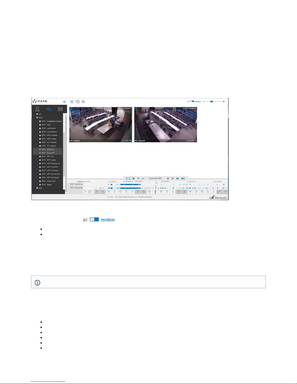
Copyright 2017 VIAAS, Inc.
Timeline Panel
The displays cameras you select( with their corresponding timelines), with blue bars indicating detected motion and recordedTimeline Panel
video. You can drag the timeline to review stored assets (images and/or video) for your cameras. The Timeline Panel allows you to quickly move
through time to locate images and events. It can display up to 16 cameras at a time.
Playhead
The is a vertical line drawn through the center of the timeline, indicating the time of the video you are currently viewing. The time isPlayhead
displayed in large digits above the Playhead.
Each camera viewer in the upper portion of the screen displays the recorded image closest to the current Playhead position in the lower portion
of the screen. The actual image time is indicated by the solid blue triangle on the respective camera timeline. Each image viewer displays a
timestamp indicating the exact image time.
Selecting Images to Display
Use the to control the types of thumbnail images displayed:Image Type Selector
all – Camera viewers show both motion images and preview images, possibly taken when no motion was detected.
motion – Camera viewers show the motion image captured closest to the Playhead position. Note that when the camera viewer displays
a preview image captured between motion events, you cannot click the camera viewer to play the event; there is no event to play.
Using this feature, you can set motion detection on a specific camera to trigger only on large objects, for example, a car pulling into your parking
lot. With this setting, something small, like a cat walking across the parking lot, does not record full motion video and does not create a timeline
event. If you select to view all images, including preview images, then you can drag the timeline to view all preview images and find the exact
time a cat crossed the parking lot. This can help you tune your camera capture settings to record only events that matter; the previews let you see
what the camera record. didn't
Timeline Navigation
There are several different ways to move the Playhead, which are useful for different reasons. The complete list is:
Using the Playhead Navigator
Using the Arrow Keys on the Keyboard
Dragging the Timeline
Clicking the Calendar
Using Play Mode
Next/Previous Block in Images Panel
Using the Playhead Navigator
The Administrator can set Motion Sensitivity in the camera's Configuration Panel. Refer to .How to Configure a Single Camera
Page 60

Copyright 2017 VIAAS, Inc.
The is a panel of buttons at the top of the Playhead. In addition to zoom buttons, the Playhead Navigator has four buttons Playhead Navigator
for navigating images, a button to reset the Playhead position to the current time, and a button for creating spans.
A description of the Playhead Navigator controls functions follows:
Using the Arrow Keys on the Keyboard
Use the arrow keys on your keyboard instead of the arrow buttons in the Playhead Navigator, described above.
press left or right arrow key – Move to the previous or next image.
hold SHIFT key, and press left or right arrow key – Move to the previous or next motion thumbnail image.
These keys, like the Playhead Navigator buttons, move through all images. By contrast, some images may be skipped if you drag the timeline
when it is zoomed out.
Dragging the Timeline
Use your mouse to click and drag the timeline under the Playhead. Each camera viewer continuously updates the displayed image to the one
closest to the Playhead position. The performance of this feature depends on the speed of your internet connection and your computer, and on
your setting, but it looks and feels like a draggable time-lapse movie. If the image updates are slow, drag more slowly,Image Type Selector
release the mouse button, and stop dragging for a moment, or zoom in a bit. When you drag back over a time period again, the browser cache
provides improved performance.
Clicking the Calendar
The Calendar displays directly below the timeline, with an orange highlight showing the date currently displayed. The size of the orange highlight
changes, depending on the scale of the time blocks. For larger time blocks, more time shows in the timeline, with a larger orange highlight.
Click on the calendar to quickly navigate to any date. Click and drag the calendar forward or backward in time. How far back you can go depends
on the retention time included in your service plan.
To reposition the calendar to , click the button in the Playhead Navigator.today Now
Using Play Mode
To activate , press the spacebar on your keyboard. To exit , press any key or click the mouse anywhere on the screen.Play Mode Play Mode
Play Mode is the same as clicking the Next Image button repeatedly – it moves the Playhead position to the next image, updates any camera
viewers that change as a result of the move, then as soon as all camera viewers display the new images, moves the Playhead position again.
The following factors require such large amounts of data that they affect the speed of Play Mode:
Showing all images, including previews
Having short intervals between preview images
Selecting several cameras to watch at once
Having a slow network connection speed
As with dragging the timeline, Play Mode improves due to your browser cache and plays faster on a second pass.
Note: At low timeline zoom levels (zoomed out to 24 hours/block, for example) the Timeline Panel cannot possibly access every single
image. Typically, the 30 minutes/block zoom level allows access to all recorded motion thumbs. In the most extreme case, if you are
recording one preview image per second, dragging the timeline must skip over some images, unless you zoom in to the 5
minutes/block level. In addition to zooming in on the timeline, you can use two methods described below to view all images: Using the
and .Arrow Keys on the Keyboard Using Play Mode
Page 61

Copyright 2017 VIAAS, Inc.
1.
2.
3.
Images Panel Navigation
The and the share the Playhead position. When you switch from Timeline Panel to Images Panel, the centerTimeline Panel Images Panel
image on the Images Panel is the image closest to the current Playhead position. If you use the Next and Previous buttons in the Images
Panel to move through time, the Playhead position in the Timeline Panel moves to match the center image on the Images Panel. When you
return to the Timeline Panel, the Playhead position has changed to match the last block of images that you viewed in the Images Panel.
Playing Clips from the Timeline Panel
There are two ways to play a clip from the Timeline Panel.
Click the Camera Viewer – When the Playhead is over a motion event, click the camera viewer to play that event. If a video does not
play, and a play icon does not appear when you hover over the camera viewer, the Playhead is not over a motion event for that camera.
Use the Next or Previous Thumbnail buttons to move to a motion event, then try again.
Click the Blue Event Bar in the Timeline – Click directly on a blue event bar in the timeline. The more a Timeline is zoomed in, the
easier it is to click an event.
Once a clip is playing, use the arrow buttons within the Player to navigate to next and previous events. This navigation does not move the
Playhead position; the timeline has not moved when you close the Player.
Creating a Time Span
You can create a span, comprising several different events, which you can then view as a single video segment. Within this video segment, time
between motion events is removed, so you only spend time watching the action.
To create a :Time Span
On the Playhead of the view, click the button .Timeline Time Span
The black appears on the timeline as a vertical line with a black marker in the center, as shown here. Time Span
Click and drag on either or both sides of the black marker to create a . The appears dark gray, bounded by theTime Span Time Span
two black rectangles, as shown below.
Within the is a play button for each of the cameras within the timeline. Click the appropriate play button to view the video Time Span Tim
for the desired camera.e Span
For the lower camera in this example, the video will show all of the short events strung together in one video segment, withTime Span
the white spaces between events eliminated.
You can drag the to a new location or click the button again to remove the from the timeline.Time Span Time Span Time Span
Timeline Filmstrip
The displays a series of images from a camera. Display or hide the Filmstrip by clicking the small triangle next to the camera name onFilmstrip
the timeline.
Page 62

Copyright 2017 VIAAS, Inc.
Displaying the filmstrip gives a quick overview of activity for the camera (the block under the Playhead displays the image closest to the
Playhead), either a thumbnail or preview, depending on the setting of the Image Type Selector. The blocks to the left and right display the last or
first image for that block – whichever is closer to the Playhead.
If you display multiple filmstrips, the timeline may be taller than the space available. Just as when you display many cameras at once, you can
scroll the timeline up and down, either by dragging it vertically, or by using the scroll wheel on your mouse.
You can create a Time Span within the Filmstrip. Refer to the Time Span section above for details.
Orange Bars in Timeline
An orange bar on the Timeline Panel indicates that a camera cannot communicate with the servers and is essentially offline.
When this happens, the camera continues to function normally, as long as it has power. If a camera is offline, its status in the NOW Panel
displays in orange. VIAAS sends an offline alert to let the administrator know.
Cameras might go offline if your local network or Internet connection go down, or if you make changes to your network.
Standard Features
Standard Features on the Timeline Panel include:
Tool Name Description
Image Size Tool Use the slider to make each camera image
larger or smaller. The smaller the image, the
more images you can fit on a single screen.
Show/Hide Side Panel Click this icon to show or hide the side panel.
If you do not need the navigation
functionality, hiding the side panel provides
more room to display camera images.
Page 63

Copyright 2017 VIAAS, Inc.
1.
2.
3.
1.
2.
Saved Events Functions
Save motion events to keep them longer than the standard time allowed with your plan, typically 30 days, when unsaved images are deleted.
Events are saved until you delete them.
Viewing Events
To view events, click the Events icon on the side panel.
You can view events you created previously, sorted by time. Most recent events display at the top of the page.
Creating Events
To create an event:
Select a recorded event from the or and play it.Timeline Panel Images Panel
In the Player, hover over the Player Tools menu and select .Add an Event
Give the event a and , then click .Title Description Add Event
The event displays in the Events Panel.
Deleting Events
To delete a saved event:
In the Events Panel, hover over the lower left corner of a saved event to display the button.Delete Event
Click , then click to confirm the deletion.Delete Event Yes
Saved Element Functions are available with Premium and Professional Service Plans only.
Page 64
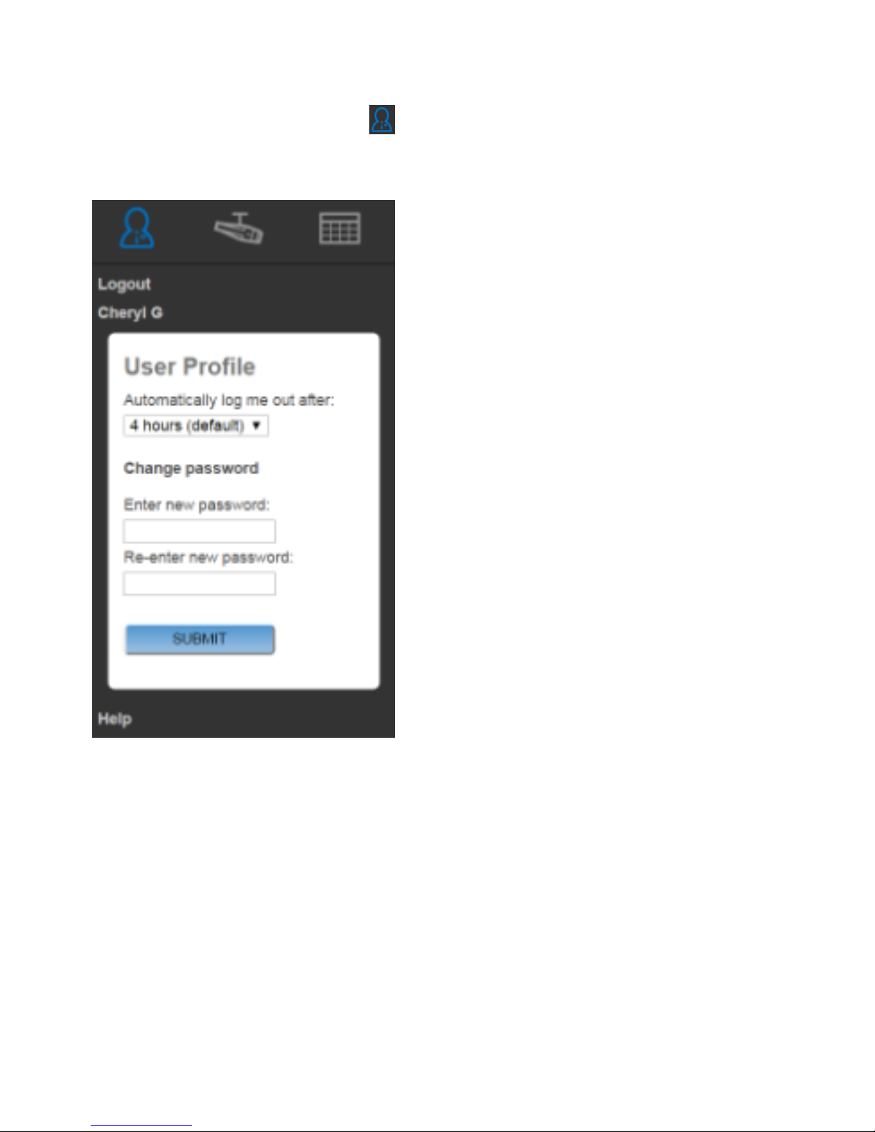
Copyright 2017 VIAAS, Inc.
How to Update Personal Information
To access your personal information, click the Admin icon on the top of the left panel.
These functions are available to all users, regardless of their Role.
When you have finished making your updates, click .Submit
Changing Your Personal Profile
Click your name on the side panel to make basic updates to your profile.
Logging Out Automatically
Spelect an amount of time before the system automatically logs you out. You may manually log out at any time.
Changing Password
Specify a new password for your profile. Then re-enter the new password.
Page 65

Copyright 2017 VIAAS, Inc.
1.
2.
3.
How to Use the VIAAS Mobile App
You can view images from your VIAAS cameras from your mobile device using the VIAAS Mobile App – anytime, anywhere.
To use the VIAAS App:
Download and install the VIAAS app from the Google Play Store or iTunes App Store.
Accept the media permission request.
When you open the app, log in using your VIAAS credentials.
To view a demo, shake your device.
Default View of All Cameras
When you launch the app, you will see all of your cameras, along with corresponding thumbnails, in an alphabetical list. These preview
thumbnails update periodically, just like in the NOW panel on the Web interface. The administrator can specify the preview frame rate for each
camera in its settings.
Click a camera name or image to view the equivalent of the Timeline view for that camera.
Timeline View
In this view, the app displays images captured during motion events.
Page 66
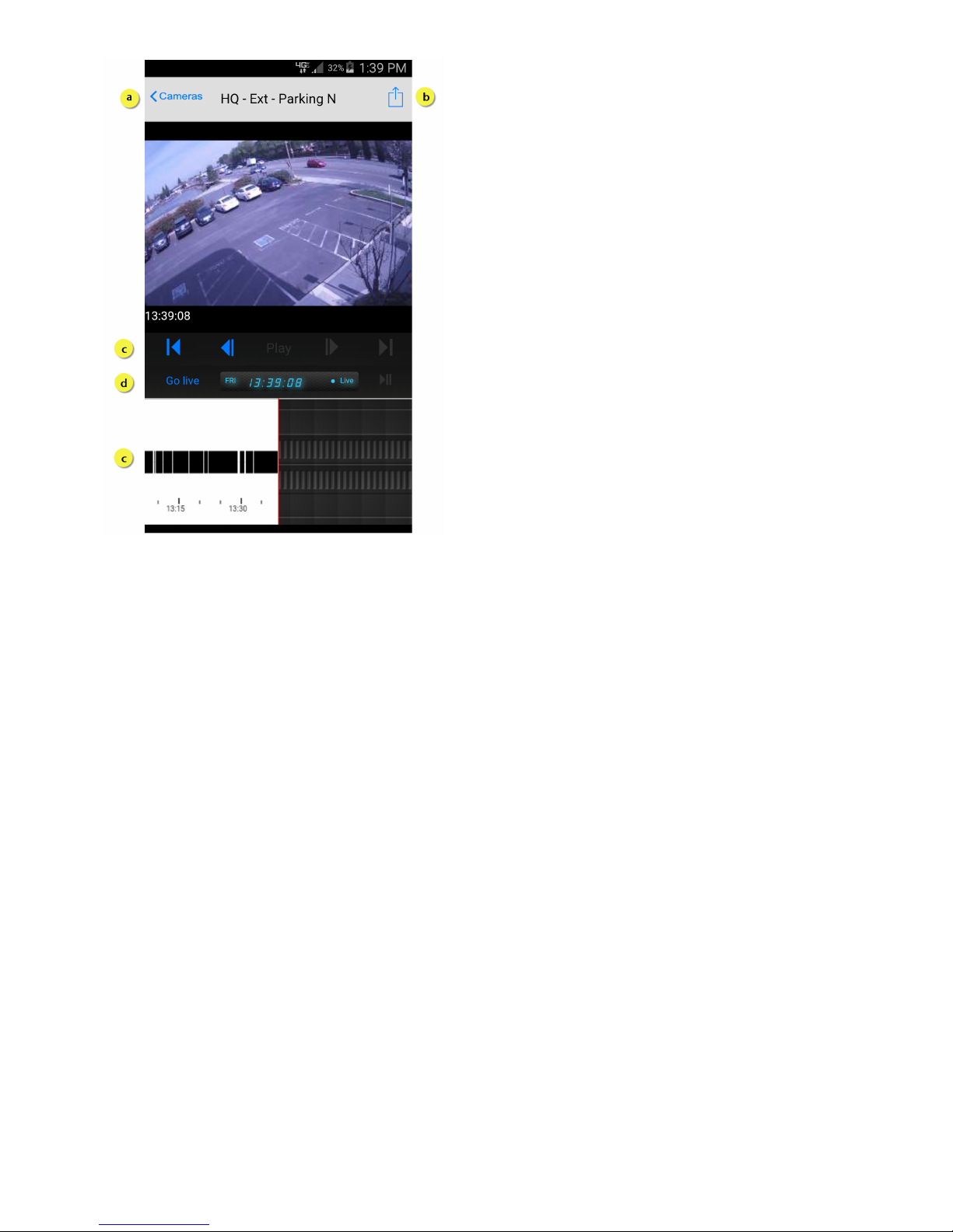
Copyright 2017 VIAAS, Inc.
a.
b.
c.
d.
Actions available on this screen:
Return to the view of all cameras.
Click the Upload button email or save the current image.
Drag the to find specific motion events. Use the play and skip buttons on the playhead to view videos.timeline
Click to see full-motion video streaming from the selected camera.Go Live
When you have finished with your session, be sure to log out from the default page.
Page 67
Copyright 2017 VIAAS, Inc.
1.
2.
3.
Troubleshooting
The following are responses to common issues and frequently asked questions.
The camera is taking too long to respond to my configuration settings. What do I do?
Configuring VIAAS cameras requires some patience. When working with the browser interface, you are sending commands to the cloud service,
which then communicates to the camera. This creates a time lag of several seconds, depending on location, network speed, and network traffic.
Please be patient when configuring your cameras.
I can't find my VIAAS camera(s).
Look for the camera in the Camera view:
In the view, click the arrow next to to view the list of all cameras. Cameras are listed in alphabetical order. ScrollCamera All Cameras
through the list to see your camera.
If your camera is not in the view:Camera
Cameras you ordered from VIAAS are automatically registered to your account. If you received your camera some other way, or if
something broke, you will need to add the camera to your account, as described in Administrative Functions. You will need to have your
camera's serial number, which is on the printed label on the camera.
Where are my Saved Events?
Saved Element Functions are available with Premium and Professional Service Plans only.
Refer to Saved Events for more information.
I can't see any footage.
Since VIAAS cameras typically only record when there is activity, it may be that everything is working fine, but nothing has happened recently. To
check this:
Select and navigate to the . Camera Functions NOW panel
Locate the camera you want to check.
At the bottom of that camera's frame, click . Within a few seconds, you should see live video in a new window, letting you knowGO LIVE
that the camera is operable.
If you see an error message, the camera is not connected to the service. Check the LEDs and read the section below about the blinking LED
lights.
The software won’t load.
Check the following:
Can you reach the website? Since you are reading this, you probably can. Since the Adobe Flash application is hosted on the same
systems as the website, you likely have an issue with your computer.
Are you running a supported version of Adobe Flash? VIAAS needs Flash version 10.0.22 or higher. Your system should automatically
upgrade and install Flash. To check your version, visit Adobe's Flash website at http://www.adobe.com/software/flash/about/. This site
will state your version and help you upgrade to the latest version.
Do you have enough memory? VIAAS strongly recommends at least 1 GB of memory in your machine.
Some browsers do not support Flash version 10. iPad, game consoles, and mobile phones are the most common. Use the mobile client at m.Cud
aCam.com to access your events.
Is my connection secure?
VIAAS is extremely secure. Captured video is encrypted and digitally signed on the MicroSD card, and it remains encrypted in motion and when
stored in the VideoVault hosted in Barracuda’s secure cloud. The images can be viewed over an HTTPS connection.
Page 68

Copyright 2017 VIAAS, Inc.
Most importantly, the cameras do not connect directly to your network and therefore do not expose your network to external threats. Instead,
cameras connect directly to the VIAAS service and authenticate themselves. This outbound connection model prevents a huge class of security
issues faced by facilities-based solutions where end users connect directly to your video archive.
My network is down. Now what?
VIAAS cameras are resilient to connection issues. They will automatically recover when your network comes back. If you are using Bandwidth
Shaping, described in Configuration Panel, VIAAS records video during the outage. For a more in-depth discussion, see the answer to the next
question about blinking LED lights.
You can power cycle the camera to accelerate reconnection.
I just plugged in my camera and the LEDs are not doing the 2 second blinking pattern the manual describes, what do I
do?
If the camera is showing solid LEDs or has one LED blinking and the other solid after it has gone through the alternating LED phase, it is having
problems connecting to the VIAAS service.
The camera needs two things to connect and one of them is broken:
an IP address, and
the ability to reach the service
Page 69

The camera can get an IP address through three mechanisms - static, DHCP, and automatic. By default, the camera will first try to find a DHCP
server and get an address. If it fails, it will use auto detection, which listens for network traffic to determine a subnet, probes for an empty IP
address, grabs a vacant address, and tries to connect. This usually works, but it can take a long time. If you are not blocking anything or you do
not know much about networking, you can wait and the camera will likely figure it out.
Once the camera gets an address, it tries to connect outbound to VIAAS (almost as if it was a browser) over ports 733, 443 (the SSL port),
and then 80. If you know you are blocking or filtering all of these ports for outbound traffic, you will need to adjust your network configuration.
If you are unable to connect the camera to the VIAAS cloud service, call VIAAS Technical Support at 408-342-5570.
Page 70

Copyright 2017 VIAAS, Inc.
What can I do about poor video quality?
VIAAS works well in most lighting situations. The Ultra High Dynamic Range (UHDR) gives you usable imagery in deep shadow and bright
sunlight, in indoor/outdoor scenarios, and if you have lights in the image. At the very high end of the dynamic range, contrast and colors tend to
flatten out and you will see some color washout or red tinge.
The only real limitation of UHDR is in low-light situations. If getting quality imagery in the dark portion of the scene requires gain (multiplication of
the light value, not just increased exposure), it rapidly defeats the UHDR. The gain threshold is in the range of 10lux, something around dimly lit
indoor lighting.
If you have this scenario and your are seeing images washed out in the bright areas, you can either try to change the camera framing to eliminate
the darkest area, or provide some additional lighting in those areas. In future releases, we will provide ways to do this electronically.
My video and images in the dark are really noisy. What can I do?
VIAAS is aggressive about trying to get usable images in all cases. At the extremes of its capabilities, it generate noisy images and video. The
only real solution to this is to add more light. Consider using an external IR Illuminator if you are monitoring a limited area. It is extremely effective.
A motion-activated flood light is another good choice.
Page 71

Copyright 2017 VIAAS, Inc.
How to Adjust from a Previous Release
If you have already been using VIAAS from a previous release, consider adding locations and roles to use all of the functionality of this release.
Locations
With this release, your cameras are all assigned to a default location. This will not affect your cameras or anything else in your system. It is your
choice if you want to make any adjustments.
To rename or add camera locations, refer to How to Manage Locations.
Users and Roles
The users in your system have not changed with this release.
All users are currently assigned a Custom role. Only the Superuser role exists in addition to the Custom roles.
To decide if you want to user roles, read Understanding Permissions and Roles.
If you choose to use roles, refer to How to Manage Users and Roles to create roles and then add users to them.
Camera Groups
Any camera groups you created still exist as My Groups and, as with previous releases, cannot be shared with others.
A new feature adds the ability for superusers to create shared groups that are visible to all users who have permission to view cameras in the
group. Refer to Understanding Camera Groups and How to Manage Camera Groups for details on that feature.
 Loading...