

Page 1

IEEE 802.11 b/g MiniPCI Wireless
User’s Manual
Version: 1.0 – January 2005
Page 2

Copyright Statement
No part of this publication may be reproduced, stored in a retrieval system, or
transmitted in any form or by any means, whether electronic, mechanical,
photocopying, recording or otherwise without the prior writing of the publisher.
TM
Windows
Pentium is a trademark of Intel.
All copyright reserved.
98SE/Me/2000/XP are trademarks of Microsoft® Corp.
Page 3

Table of Contents
1 Introduction......................................................................................................4
1.1 Product Overview........................................................................................5
1.2 Main Feature of 802.11b/g MiniPCI adapter................................................6
1.3 System Requirements.................................................................................6
2 Wireless Network Concepts............................................................................7
2.1 Wireless LAN Network Modes.....................................................................8
2.2 Planning Your New Wireless Network.......................................................10
3 Installation Instructions ................................................................................14
4 Utility Configurations ....................................................................................18
4.1 Configuration for Windows 98 SE / ME / 2000 ..........................................18
4.2 The WLAN Management Utility (Windows 98 SE / ME / 2000) .................19
4.3 Configuration for Windows XP...................................................................27
5 Uninstall..........................................................................................................30
5.1 Uninstall Driver and Utility .........................................................................30
Appendix A.. ... .. .. .. .. .. ... .. .. .. .. .. ... .......................... .. .......................... .. .................32
Glossary..........................................................................................................32
Page 4
1 Introduction
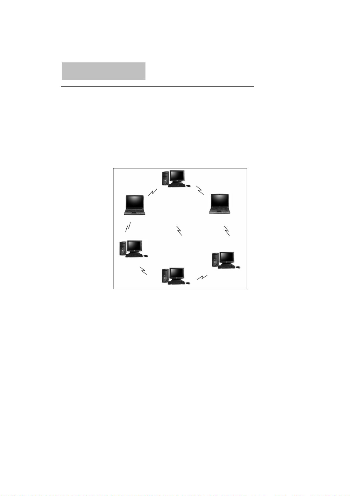
Congratulations on your decision to use wireless networking. The 802.11b/g
Wireless LAN Card is a high performance, IEEE Standard 802.11b/g
compatible, wireless networking card that installs into your PC’s slot to
support wireless LAN communications at speeds up to 54Mbps with other
PC’s located hundreds of feet apart.
Figure 1 Typical Wireless LAN Network
The 802.11b/g Wireless LAN Card allows reliable, secure and untethered
access to your data providing you with exciting new ways to adapt to your
lifestyle and needs. Without the limitations of wires, true mobility and data
access is seamless in your office or home office.
Data access from work, streaming audio MP3’s from a notebook to a stereo,
downloading Internet content wirelessly from a broadband connection,
watching TV on a notebook, are all possibilities with the 802.11b/g Wireless
LAN Card.
4
Page 5

1.1 Product Overview
The 802.11b/g Wireless LAN Card gives you the freedom of secure highspeed communications with other PCs without the need for interconnecting
wires. You can even connect in to other LAN infrastructures such as your
company’s internal Ethernet LAN or your own home network. The antenna
and design of the Wireless LAN Card gives you unmatched sensitivity which
means your system will remain connected to other wireless PCs at high
speeds for longer distances.
The Wireless LAN Card operates according to the IEEE 802.11b/g Wireless
LAN specification, for wireless data communications at speeds up to 54Mbps
(Megabits per second). IEEE 802.11b/g operates on frequencies in the
2.4GHz range using OFDM (Orthogonal Frequency Division Multiplexing)
technology.
Backed by international standards and the IEEE organization, IT departments and
end-users alike benefit from the reliability and int eroperability of products based on
these standards. From an investment point of view, it makes good business sense
investing in technology that will be support worldwide for many years to come
(unlike technologies not backed by international communications standards). Whether
you are running a company or a home office, the Wireless LAN Card reduces, or
eliminates in some cases, the need to setup wired LAN networks in the of fice or home
office, eliminating costs associated with wiring rooms and buildings.
5
Page 6

1.2 Main Feature of 802.11b/g MiniPCI adapter
• Up to 54Mbps data transfer rates for high-speed access to data
• Compatible with 802.11g Wi-Fi CERTIFIED equipment (2.4GHz operating
range)
• Plug-and-play with Microsoft Windows operating systems
• Secure data access, up to 128-bit WEP encryption protection
• Backward Complain with 802.11 b.
• Support both Ad Hoc Mode and Infrastructure Mode Access.
1.3 System Requirements
• PC with Windows 98 SE, Windows 2000, Windows ME, or Windows XP
Operating Systems
• An available mini-PCI slot on computer.
• CD-ROM drive (for the drivers and configuration software)
• A minimum of 10 MB o f free disk space for installing the driver and utility
program.
• Another IEEE 802.11b or 802.11g compliant device installed in your
network.
6
Page 7

2 Wireless Network Concepts
For the past few decades, wired Local Area Networks (LAN) or more
commonly know as Ethernet, have provided a seamless way of connecting
and communicating with multiple PCs, desktops, laptop/notebooks, servers
as well as a host of other peripherals, including printers, scanners, etc. LANs
have served us well in environments where users were not mobile or had little
need to access data other than in their office.
With the advent of notebook computers and an increasingly mobile computing
society, the need for wireless networking finds more applications with each
passing day. Wireless LANs have evolved to meet the needs of mobile
computing and are becoming very popular as compatibility, reliability and
familiarity increases and equipment costs decrease.
Wireless LANs (WLAN) allow users to roam freely about a network taking
their computers with them while still maintaining a networking connection. In
essence, WLANs are an extension of wired LAN networks, where the critical
need is data access and mobility. The tradeoffs are slower speeds (although
quite satisfactory for Internet and email access) and limited roaming distance,
as dictated by the environment.
A basic WLAN network requires client nodes and access points, similar to a
LAN with its clients and infrastructure (switches, repeaters, etc.). The access
point is the connection to the wired LAN network or a designated computer
device performing the supervisory function, while client nodes are typically
WLAN adapters installed in peripheral computing devices, such as notebooks,
desktops, personal digital assistants (PDAs) and others. Once a WLAN is
setup, it acts like a wired LAN, using the same protocols designated for
communicating via the IEEE Ethernet standard.
7
Page 8
2.1 Wireless LAN Network Modes
WLANs basically have two modes of operation:
• Ad-Hoc mode
• Infrastructure mode
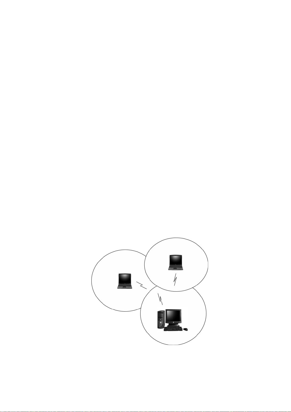
Ad-Hoc Mode
An Ad-Hoc WLAN is created when two or more PCs equipped with Wireless
LAN Cards (WLAN clients) are configured to use the same radio channel and
Network Name in the same area and can communicate freely with each other,
without the need for an Access Point to a hard-wired LAN network. Only PCs
that use the same radio channel and network name can communicate over
the Ad-Hoc network. This type of a network is a peer-to-peer relationship
where each computer talks directly to one another with no one PC being
dominant.
8
Page 9

Figure 2 Ad-Hoc Mode: Two or More PCs with 802.11b/g Wireless LAN
Cards
Configured to Same Radio Channel and Network Name
Infrastructure Mode
When a WLAN access point is introduced into the WLAN, the access point
and its clients (each PC) comprise a Basic Service Set (BSS), whereby the
access point serves as the connection to the wired LAN for each client.
Clients within the same BSS do not directly communicate between each other;
rather they communicate to the AP that routes the data to the appropriate
destination.
The access point bridges both wired and wireless networks, allowing wired
and wireless client communication. This arrangement of WLAN access points
and clients is commonly referred to as Infrastructure mode. An access point
also extends the range of the WLAN, double over that of client only networks
because the access point is able to forward data within its BSS.
Infrastructure mode enables the network clients to freely roam, once an ESS
(Extended Service Set) is established.
With all clients using the same radio channel and ESS ID (sometimes referred
to as SSID which is a given name to the network), users are fully mobile
within the range of the access point signal. Access points should be situated
in location to deliver the largest range of signals, with minimal interference.
Best performance and signal quality is often affected by building structures,
walls, etc., and may require some trial-and-error to identify the best location
for access points.
9
Page 10
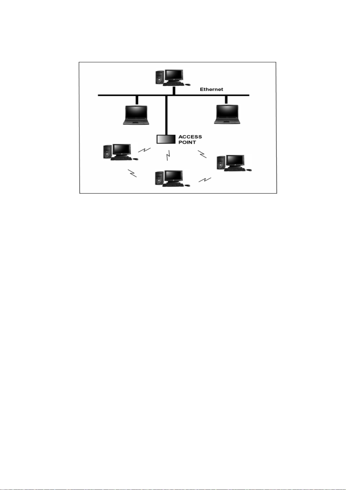
Figure 3 Infrastructure Mode-Combination Wireless and Hardwired
LANs
2.2 Planning Your New Wireless Network
First, determine what components (WLAN cards, access points) and what
kind of network will be created (Ad-Hoc, Infrastructure mode). Then select
your network name (SSID), WEP key (security password) and channel
number (1 through 11 in US, 1 through 13 in Europe and 1 through 14 in
Japan). All members of the wireless LAN will have to configure their PCs to
the same SSID, WEP and Channel number to talk to each other. SSID, WEP
key and channel number are essential to understanding and creating a
successful wireless network.
These concepts are explained in the following paragraphs.
10
Page 11

SSID
A wireless network requires a BSS or ESS to operate and a name associated
with it. SSID literally stands for a network name for use with that Service Set
of clients and access points if so set up. All computers must have the same
SSID as the network in order to communicate over the new network. The
SSID name can be any name such as “wireless_lan”, “Bob’s domain”, or
“AbCdE123”, and can include numbers as well as be case-sensitive. If the
exact SSID name is not used, then that wireless client cannot logon into that
network.
Operating Frequency (Channel)
IEEE 802.11b/g wireless LAN networks communicate using one of several
available channels (each with a different operating frequency) to reduce the
interference from other potential sources or users of that channel. Depending
on the country where the network is being set up, you may have a choice of
up to 14 channels available. In the US, channels 1 through 11 are defined for
use in the 2.4GHz spectrum used by 802.11b/g. In Europe, channels 12 and
13 are added, while Japan can have up to 14 channels. Channels 1, 6 and 11
are the most commonly used channels in the US.
For your network, choose a channel that offers little interference and
configure all users of this network to the same channel.
WEP Key
WEP provides for two levels of security encryption based on the length of bits
in a key called a Shared Key. A 40-bit key (which is 5 characters) provides
some security; this can be a key like “12345” or “MyLAN”. A 104-bit key is
also available and provides more robust security. A 13-character key is
required for 104-bit security. Keys can be in ASCII characters or Hexadecimal.
11
Page 12

ASCII characters are those used in computers and include all typewritten
characters including the alphabet and numbers, as well as */”()[] characters.
Hexadecimal characters are limited to the numbers 0-9 and the first 6 letters
of the alphabet a-f.
Table 1 WEP Key Examples
WEP Key size Number of Digits Example
5 (ASCII) 12345, MyLAN, 78E*5
40-bit (also called 64-bit)
10 (Hexadecimal) 1A37FB458C
13 (ASCII) 1234567890123,This_is_MyLAN
104-bit (also called 128-bit)
26 (Hexadecimal) 1A37FB458C12E34F8523E9FF76
Note: Every key has an added 24-bit provided by the card, which are set by
the manufacturer and not user modifiable. This manual uses the terms
40-bit and 104-bit to represent 64-bit and 128-bit keys respectively. This
is the most commonly used terminology in the industry.
The WEP key for your wireless LAN network is another form of password.
Like passwords, certain combinations of passwords are not recommended for
use (such as 01234, abcde, or publicly known information like your office
phone number, dog’s name, etc.). Protect your WEP key as you would a
password.
Note: If you access other networks with already predefined keys, always
enter them exactly as they appear taking note of lower and upper case letters.
Any computer accessing a wireless network with WEP enabled not only
requires the same SSID but also the same WEP key in order to have access.
12
Page 13

With the above factors decided, physical placement of the components will be
critical. The maximum range of the wireless LAN will often be decided by the
type of environment it is located in and, if in different rooms, by how many
obstacles are in the way which reduces the range of the wireless adapters.
Often, Ad-Hoc mode will require the wireless clients to be in closer range of
each other than Infrastructure type networks. The Wireless LAN Card can
operate at up to 100m indoors and up to 300m outdoors, although the
physical environment (walls, floors, ceilings, etc.) will limit the range of
wireless signals.
13
Page 14

3 Installation Instructions
1. Before installing driver and utility, you may skip searching drivers when
system detect the hardware.
2. Insert the installation CD into your CD-ROM drive. The setup program will
start automatically.
14
Page 15

3. Click Install Driver & WLAN Manager to begin the setup.
4. Click Next to begin the setup.
15
Page 16

5. Select the destination folder. To install to the default folder as shown below,
click Next to continue.
6. Select No and then click Finish to complete the installation (Windows 98
SE and ME users must select Yes).
16
Page 17

7. The shortcut will appear on your desktop. By click this icon, you can
run the Utility program.
8. System will detect MiniPCI Adapter automatically. Click Next to install
hardware.
9. If it shows a dialog as following, click Continue Anyway.
17
Page 18

4 Utility Configurations
Once the driver is installed, the 802.11b/g Wireless LAN Card will be up and
running. Configuration of the Wireless LAN Card is dependent on the
operating system. Please follow the instructions carefully to make sure you
are taking the appropriate steps for your operating system.
4.1 Configuration for Windows 98 SE / ME / 2000
If your PC uses Windows 98 SE, Windows ME, or Windows 2000, use the
following configuration procedure. If your PC uses Windows XP, skip this
procedure.
Utility Startup Configuration Details
The Wireless LAN Card has its own management software. Users can control
all functions provided by the application named WLAN Utility. You may run
the utility by double clicking the WLAN Utility shortcut on your desktop.
Different colors are used to describe the status of the connection icon shown
in the System Tray. Green indicates excellent connection. Yellow indicates
the connection has poor quality, and Red means no connection. Double click
the icon and the WLAN utility will be opened.
18
Page 19

4.2 The WLAN Management Utility (Windows 98
SE / ME / 2000)
The WLAN Utility contains the following four major functions. Each function is
described in detail below:
Status Tab
The Status tab provides information on the current wireless connection.
19
Page 20

Config Tab
The Config tab allow users easily configure the wireless network settings. The
options for Network Type include Infrastruct ure(Access Point) and Adhoc(Peerto-Peer) mode. The Data Rate allows you to manually set your Transmission
speed over the wireless network. You can change Channel manually on Adhoc
mode. Power Save Mode allow you to choose a power management function.
Fragment Threshold allows you to set Fragment threshold as connection.
Fragmentation mechanism is used for improving the efficiency when high t raffic
flows along in the wireless network. If your wireless devices often transmit large
files in wireless network, you can enable the Fragmentation Threshold and the
mechanism will split the packet to send. RTS Threshold allows you to set RTS
threshold as connection. RTS threshold is a mechanism implemented to prevent
the “Hidden Node” problem. “Hidden Node” is a situation in which two stations
are within range of the same access point , but are not within range of each other.
Thus, it provides a solution to prevent data collisions. Enabling RTS Threshold
may cause redundant network overhead that could negatively affect the
throughput performance.
20
Page 21

Security Tab
For more secure data transmissions, it is recommended to enable WEP on your
WLAN. The utility supports HEX or ASCII key entri es. For the HEX K e y Format ,
the security is enabled by entering 10-digit keys for the 64-bit WEP configuration,
and 26-digit keys for a 128-bit WEP configuration. For ASCII Key Format, the
security is enabled by entering 5 alphanumeric characters for the 64-bit WEP
configuration, and 13 alphanumeric characters for the 1 28-bit WEP configurati on.
Select the desired encryption strength (64-bit or 128-bit) and then enter the
appropriate keys in Key 1, 2, 3, or 4 . Remember to select the correct Default Key
by radio button.
21
Page 22

Site Survey Tab
The Survey tab supports powerful Site-Survey tool to discovery all active wireless
devices in the radio range. While selecting this wireless d evice displayed on the
screen, users can double click or click Join Network to quick connect the
wireless device. If users want to update the survey result, they can press Rescan it
button again.
22
Page 23

Statistic Tab
The Statistics tab is used to monitor TX and RX traffic of the wireless network. It
also offers the detailed information on error packets. Users can press Reset button
if they want to restart the counter again. Or press Pause to view current counting.
23
Page 24

Signal Tab
The Signal tab is used to monitor Signal Strength and Signal Quality of the
wireless connection.
Menu: Profile
The Profile is used to management profile list. You can press Add to add
currently connection to profile list. Press Delete or Delete All t o kill profiles on
list. Press Default Profile to set one profile as default connection.
24
Page 25

Menu: View
The View is used to show or hide status bar of this utility.
Menu: Option
The Option is used to launch WiFi Monitor on system bar.
25
Page 26

Menu: Help
The Help shows the copyright.
26
Page 27

4.3 Configuration for Windows XP
Using Wireless Zero Configuration on Windows XP.
1. Left-click on the Wireless Network Connection indicator icon in the
System tray (right-hand corner of taskbar) to launch the Connect to
Wireless Network window.
2. You should see the SSID of your Wireless Base Station or adhoc
network in the “Available wireless networks” window. High-light the
desired network.
3. Click
Connect
network, or click [
Properties.
to connect the Wireless LAN Card to the selected
Advanced
] to open the Wireless LAN Card
27
Page 28

4. Select your desired network from the “Available wireless networks”
window and then click [Configure].
5. You will be able to select the “Network Authentication” and “Data
encryption” methods. If you have 64 or 128-bit WEP enabled on your
network, set the “Data encryption” to WEP, uncheck the “The key is
28
Page 29

provided for me automatically” box and enter your key in both the
“Network key” and “Confirm network key” fields.
6. Then press the [OK] button. Now you will see the network’s SSID
listed in the “Preferred Networks” window. Then Press [OK] to
complete the network setup.
7. You can also click [
] button to create a configure manually.
Add
29
Page 30

5 Uninstall
5.1 Uninstall Driver and Utility
1. To uninstall the 802.11b/g WLAN management Driver and Utility, choose
Start then Programs then 802.11g WLAN Adapter, and click Uninstall
802.11g WLAN
2. Click Remove option and Next button.
.
30
Page 31

3. Click OK to remove or click Cancel to exit.
31
Page 32

Appendix A
Glossary
Access Point
A wireless LAN adapter, which connects to a wired LAN network (acting as a
bridge) and serves as the base for a wireless LAN network, directing
communication between clients. An access point is only used in Infrastructure
mode. Access Points in a business environment are typically connected to the
wired LAN network. In the home, an Access Point would be connected to a
broadband Internet device such as a Cable or ADSL modem.
Ad-Hoc
This is a wireless LAN network comprised solely of clients (no access points),
which can communicate with each other only when they are in range of each
other’s Signal and configured to the same channel and SSID.
BSS – Basic Service Set
This denotes the availability of access points and clients, all in communication
with each other. An Ad-Hoc LAN (clients only) may also have a BSS ID; all
machines must use the same BSS ID.
32
Page 33

Client
A PC, peripheral or other electronics with a connection to the network, with
the sole purpose of using the network for data access and transfer. For
example, a notebook PC with the Wireless LAN Card is considered a client.
ESS – Extended Service Set
The availability of access points and clients (BSS) and connections to wired
networks, as well as the ability for a client to roam. ESS is available in
Infrastructure mode, and all components must have the same ESS ID. Clients
within an ESS may roam freely through many BSSs, if they are within range
of the wireless LAN networks.
Infrastructure
As opposed to Ad-Hoc, this network mode allows connection to access points
and to wired LAN networks or Internet access device such as a cable or
ADSL modem.
LAN – Local Area Network
A network of clients/users typically based on the IEEE Ethernet protocol and
using TCP/IP (Internet Protocol).
33
Page 34

Roaming
Clients can freely move about the wireless LAN network (ESS).
WEP – Wired Equivalent Privacy
A shared-key encryption protocol used to provide security for wireless data.
At least two implementations of WEP exist, with keys based on the number of
bits (64 or 128-bit). The more bits in the key, the harder it is to decipher and
therefore, the more secure the connection is.
34
Page 35

Federal Communications Commission (FCC) Radiation Exposure
Statement
This device complies with Part 15 of the FCC Rules. Operation is subject to
the following two conditions:(1) this device may not cause harmful
interference, and (2) this device must accept any interference received,
including interference that may cause undesired operation.
This equipment has been tested and found to comply with the limits for a
Class B digital device, pursuant to Part 15 of the FCC Rules. These limits are
designed to provide reasonable protection against harmful interference in a
residential installation. This equipment generates, uses and can radiated
radio frequency energy and, if not installed and used in accordance with the
instructions, may cause harmful interference to radio communications.
However, there is no guarantee that interference will not occur in a particular
installation If this equipment does cause harmful interference to radio or
television reception, which can be determined by turning the equipment off
and on, the user is encouraged to try to correct the interference by one or
more of the following measures:
-Reorient or relocate the receiving antenna.
-Increase the separation between the equipment and receiver.
-Connect the equipment into an outlet on a circuit different from that to which
the receiver is connected.
-Consult the dealer or an experienced radio/TV technician for help.
Changes or modifications not expressly approved by the party responsible for
compliance could void the user‘s authority to operate the equipment.
FCC Caution
This device and its antenna(s) used for this transmitter must not be co-located
or operating in conjunction with any other antenna or transmitter.
This equipment complies with FCC radiation exposure limits set forth for an
uncontrolled environment. In order to avoid the possibility of exceeding the
FCC radio frequency exposure limits, human proximity to the antenna shall
not be less than 20cm (8 inches) during normal operation.
35
Page 36

If the FCC ID is not visible when the module is installed inside another
device, then the outside of the device into which the module is installed
must also display a label referring to the enclosed module. This exterior
label can use wording such as the following: “Contains Transmitter Module
FCC ID: SVE-611000WMC8” or “Contains FCC ID: SVE-611000WMC8”
36
 Loading...